Dane
-
Posts
25 -
Joined
-
Last visited
Recent Profile Visitors
953 profile views


-
 GrandpaPhil reacted to a post in a topic:
18th Century French Longboat by tkay11 - PSG Modeler - 1:48 - CARD - Review & Partial Build
GrandpaPhil reacted to a post in a topic:
18th Century French Longboat by tkay11 - PSG Modeler - 1:48 - CARD - Review & Partial Build
-
tkay11 reacted to a post in a topic:
18th Century French Longboat by tkay11 - PSG Modeler - 1:48 - CARD - Review & Partial Build
-
shipman reacted to a post in a topic:
18th Century French Longboat by tkay11 - PSG Modeler - 1:48 - CARD - Review & Partial Build
-
 Hello, Tony. I renewed my site and uploaded my French longboat in 1:72 scale in English. You and all modelers, who are interested in this paper model, can download this model for free.
-
Rudolf reacted to a post in a topic:
19th Century French portable binnacle
-
mtaylor reacted to a post in a topic:
Exploring FreeCAD for ship modeling
-
allanyed reacted to a post in a topic:
19th Century French portable binnacle
-
Exploring FreeCAD for ship modeling
Dane replied to TonyM's topic in CAD and 3D Modelling/Drafting Plans with Software
Hello TonyM. There is a simple method to make a grommet which is a three strand ring but made from one long strand. You should go around a grommet in three turns. As a result you get rope grommet. There is a good explanation in ABOK: 2864, 2865. The COMMON GROMMET is made with a single strand in two ways. After completing two circles with any wanted number of loose turns, start the third circuit either as #2864 or as #2865, and continue to lay the strands parallel. The ends are finished off as in a LONG SPLICE. These two starts make all possible grommets of three leads. A grommet in Manila is tied preferably with a single. strand of four-strand rope. In tarred hemp, grommets are made of small stuff, the full size. EYELET HOLE GROMMETS in sails are of marline or small wire. The length of strand required for a grommet is three times the circumference of the grommet plus six times the round of the rope.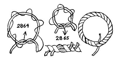

-
mtaylor reacted to a post in a topic:
19th Century French portable binnacle
-
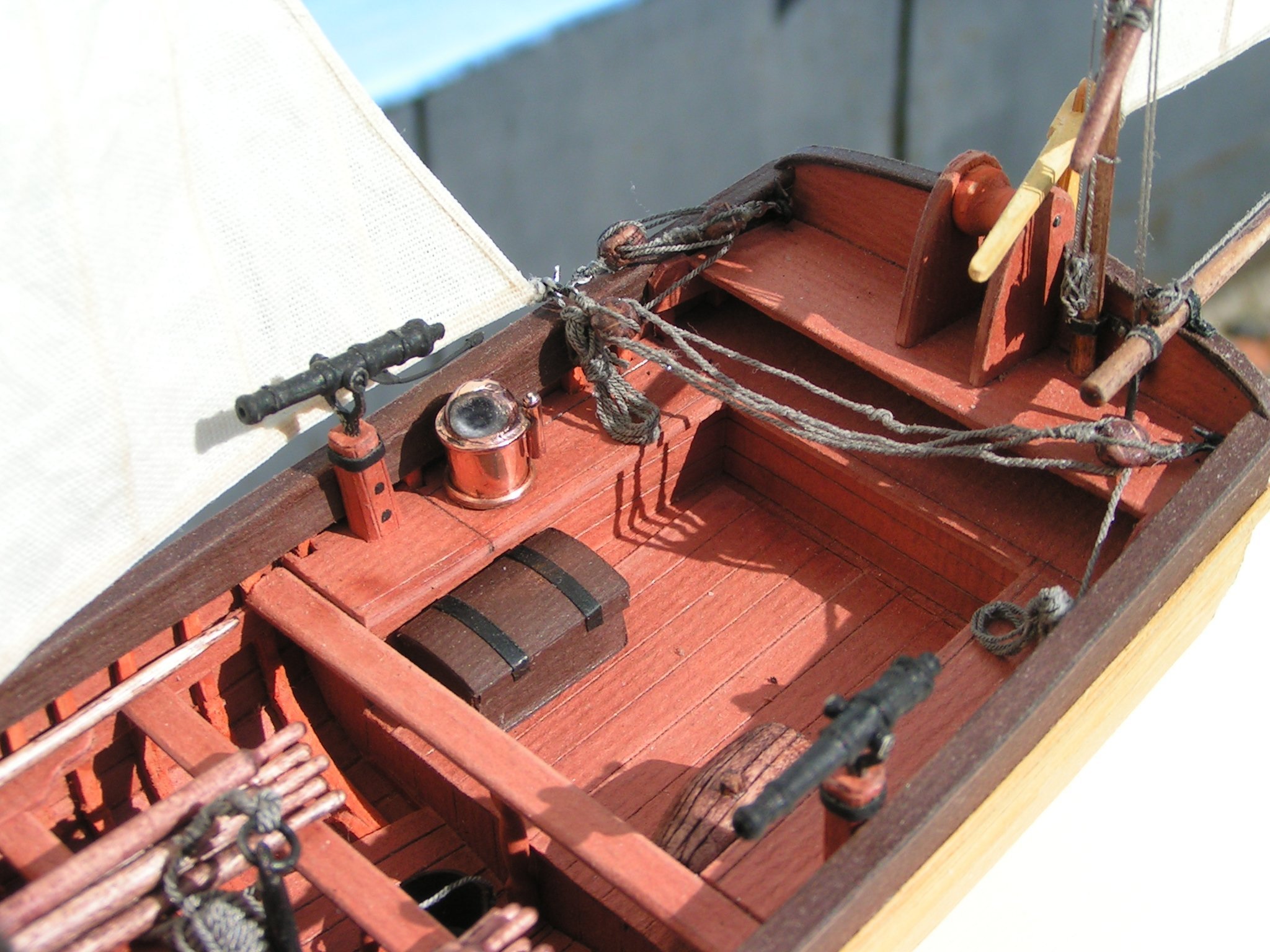
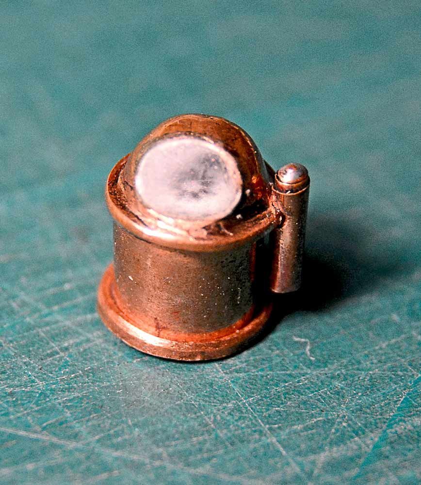
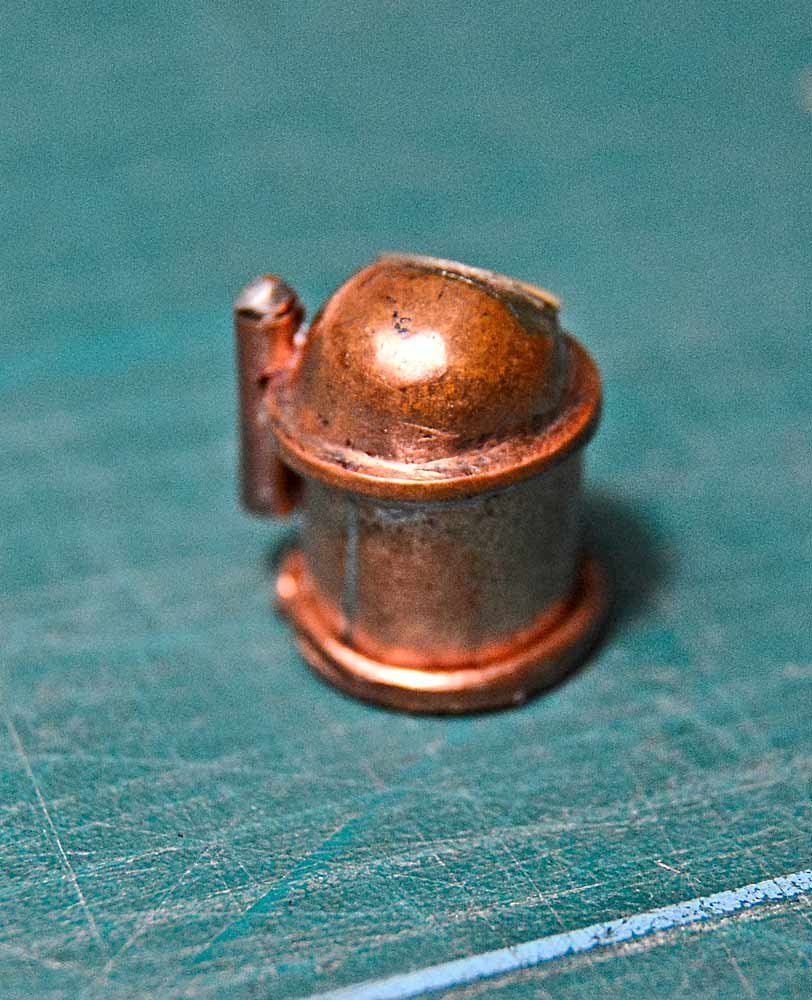
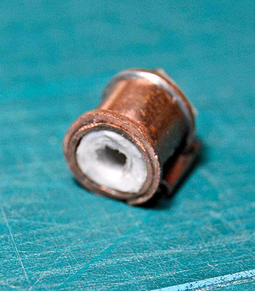
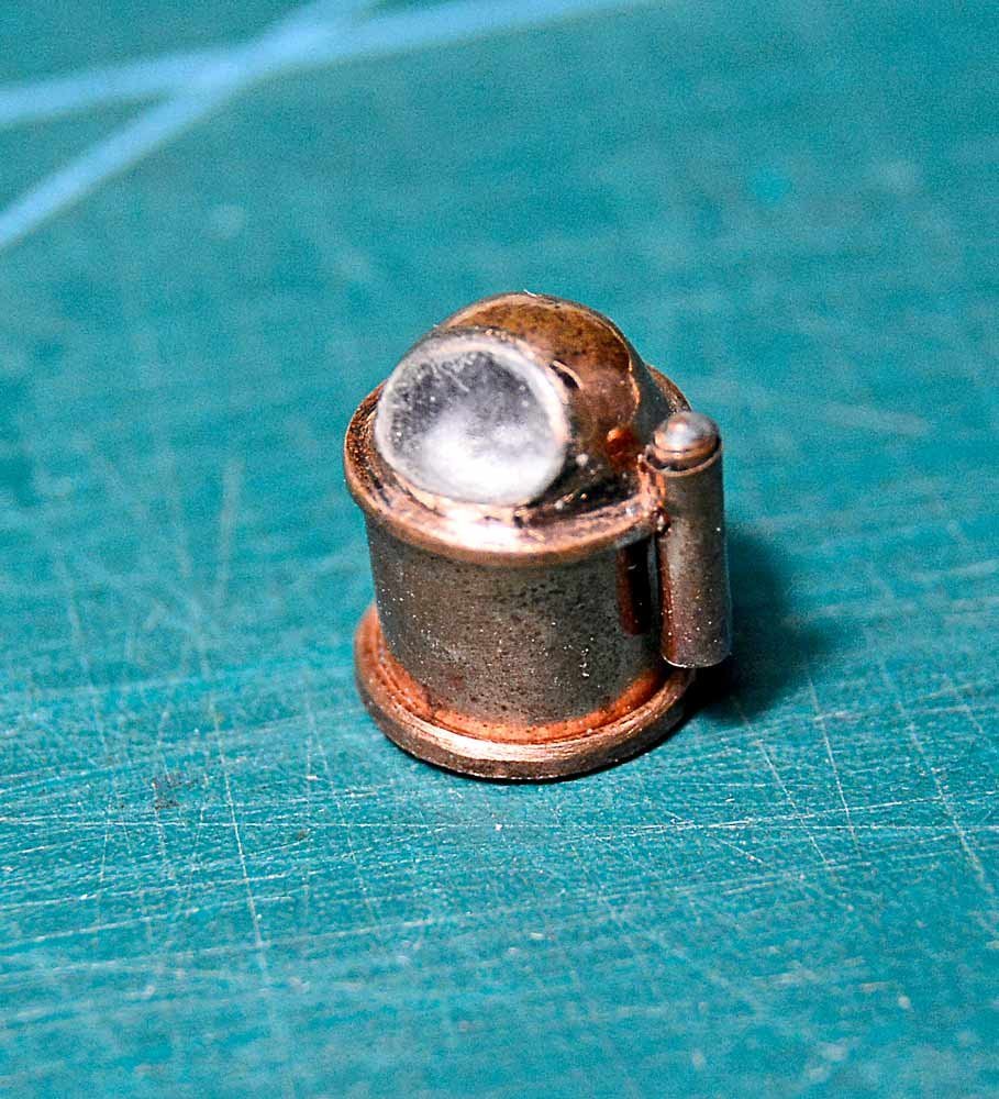
Hello to all. I occasionally take a look in this thread and decided to tell you how I built my compass. It was a very simple thing. I organized a little forge in my room. I took a piece of electrotechnical copper and flattened it. Next I made a cylinder with upper and lower shoulders made from flattened copper wire. After that I extruded a compass dome from a little copper sheet by engraving a tool with a sphere on the end. For the compass light I made a thin copper tube with a sphere on the end. To support the compass card I inputted a paper tube inside the compass copper cylinder. The scheme of the binnacle which is placed above is from my magazine PSG-Modeler. Indicated variant was made by me for the paper model. In reality I made binnacle from the copper. It pleases me more than paper binnacle.

-
KORTES reacted to a post in a topic:
La Chaloupe Armée / 42ft Armed Longboat of 1834 by tkay11 – FINISHED - scale 1:36 - plans by M. Delacroix
-
mtaylor reacted to a post in a topic:
Exploring FreeCAD for ship modeling
-
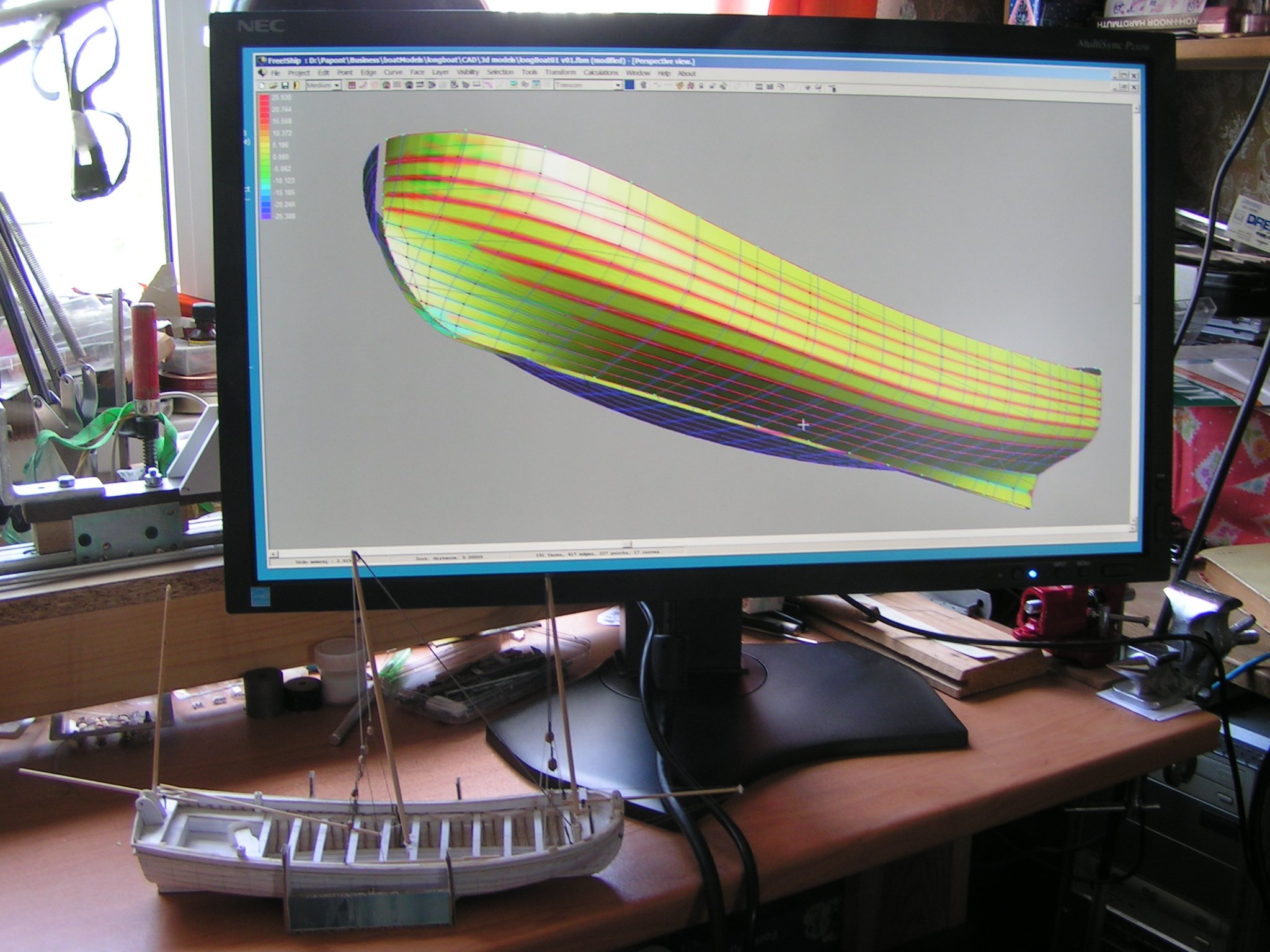
Exploring FreeCAD for ship modeling
Dane replied to TonyM's topic in CAD and 3D Modelling/Drafting Plans with Software
Did this one made from 3 strands or from 1? 🙂 -
mtaylor reacted to a post in a topic:
Help with placement of linesplan
-
Help with placement of linesplan
Dane replied to Rubkvi's topic in CAD and 3D Modelling/Drafting Plans with Software
It is impossible without a water lines plan. You must have a second projection. Or call Sherlock Holms for help. 🙂 Or you can check a theory like this. Usually frames are established at an equal distance. Therefore you can determine the positions of the frames based on the assumption of an equal distance between them in the side view. Like in the picture below.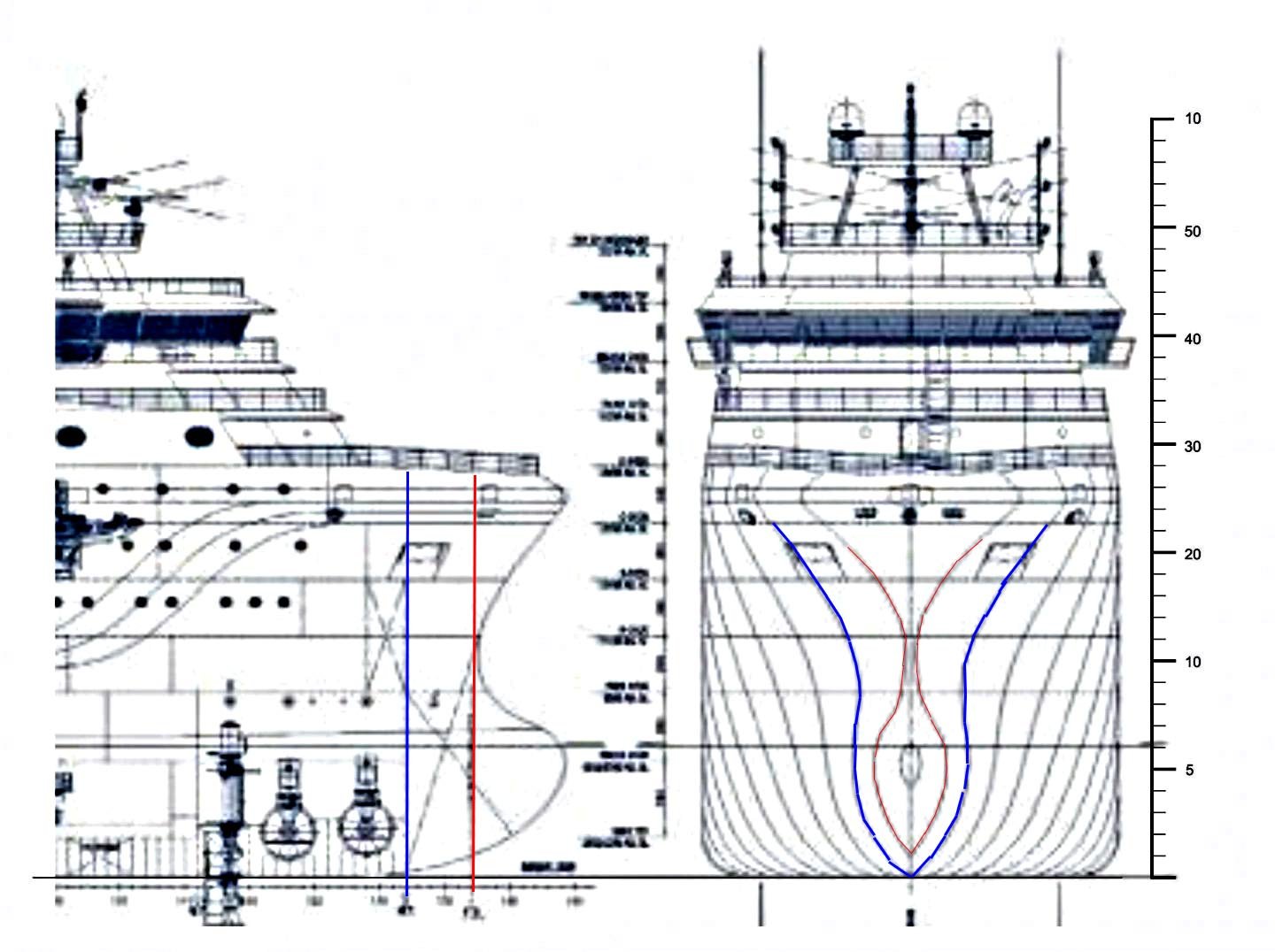
-
Help with placement of linesplan
Dane replied to Rubkvi's topic in CAD and 3D Modelling/Drafting Plans with Software
Hello. You should compare body plan and water lines plan. A station (or frame) on both plans must have the same width. -
paperdrawing transfer to cad
Dane replied to helge's topic in CAD and 3D Modelling/Drafting Plans with Software
You can trace any drawing with tracing software but the question is if the projections of the drawing are consistent with each other? To verify it you should use shipbuilding software anyway, like DelftShip for example. If the drawing includes digital data your task will be easier.
-
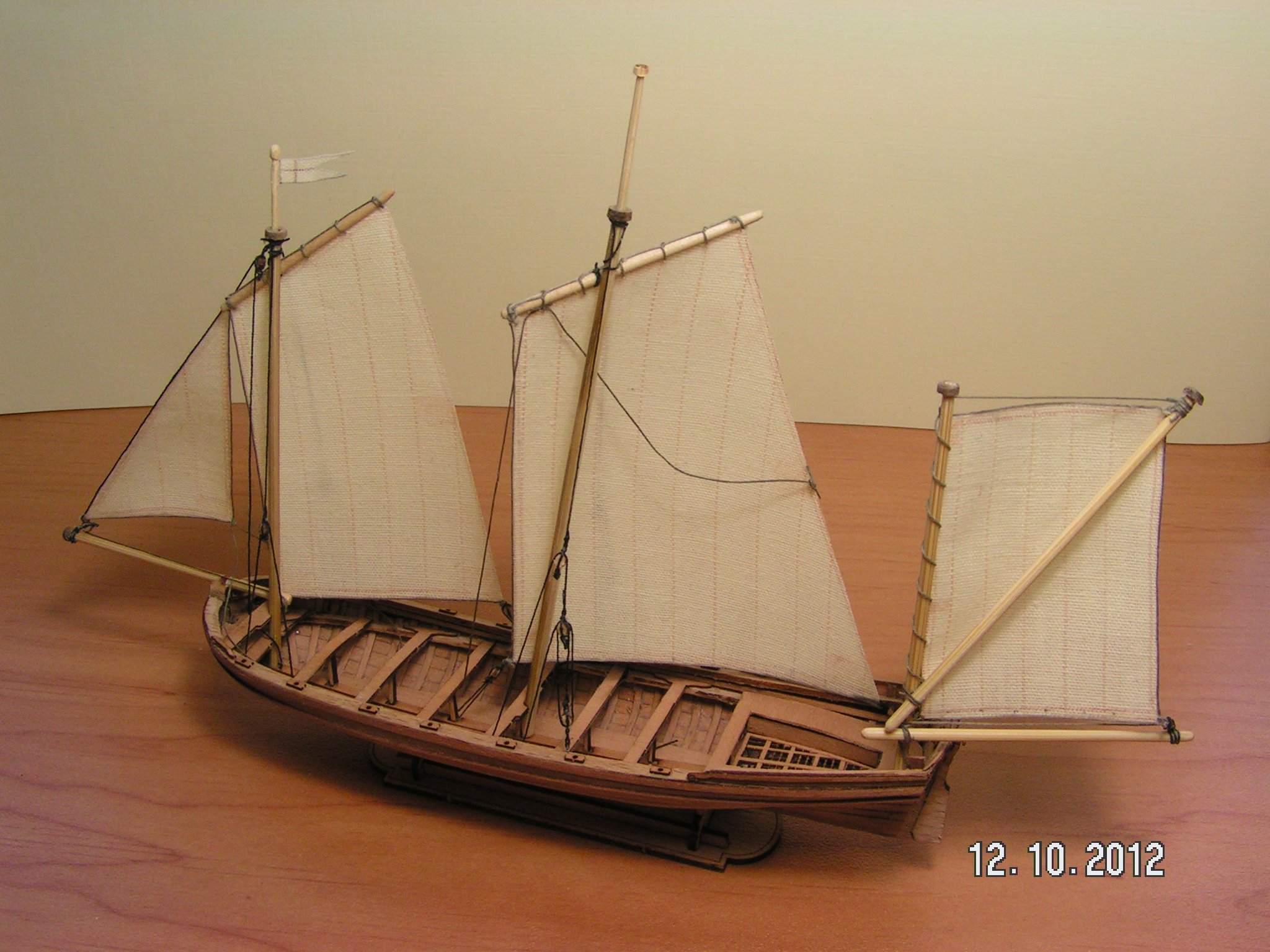
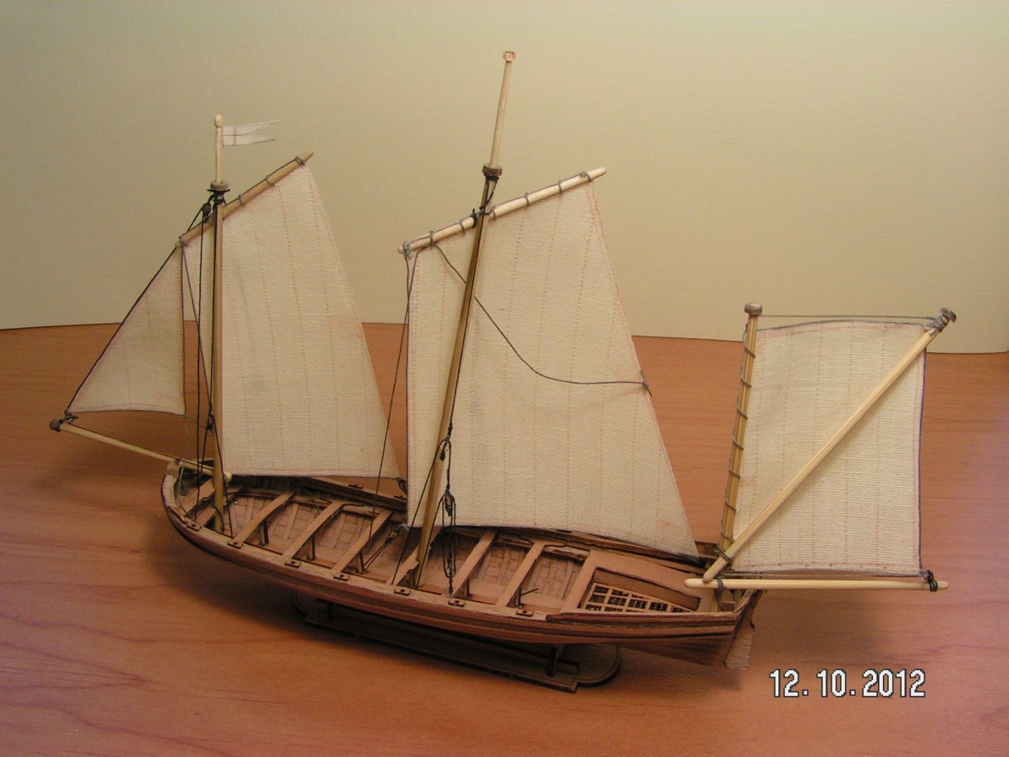
Tony, Of course! Absoluteley no! On the contrary, I have to say you grand thank that you mension my model here. Your work on this wooden model is very interesting and valuble for me. Because I haven't big experience in wooden modeling. I try to carefully watch for you work. Good luck! On the picture my most big wooden model. Lmax=about 200 mm.
- 124 replies
-
- 4
-
-
- longboat
- Chaloupe Armee En Guerre
- (and 1 more)
-
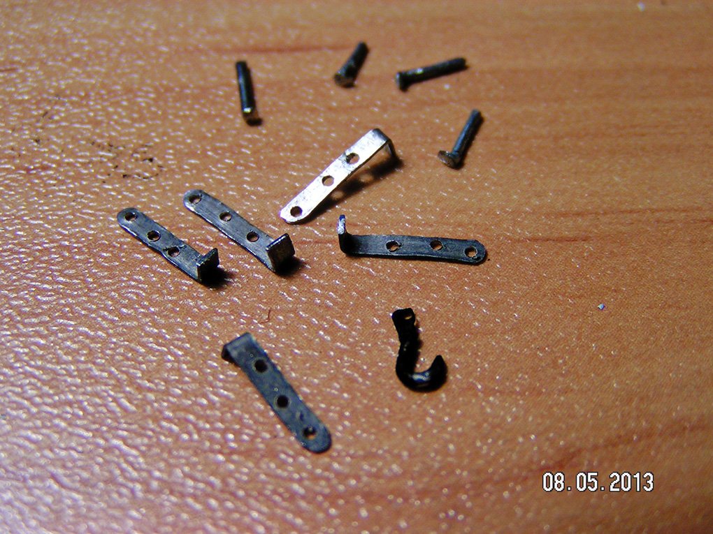
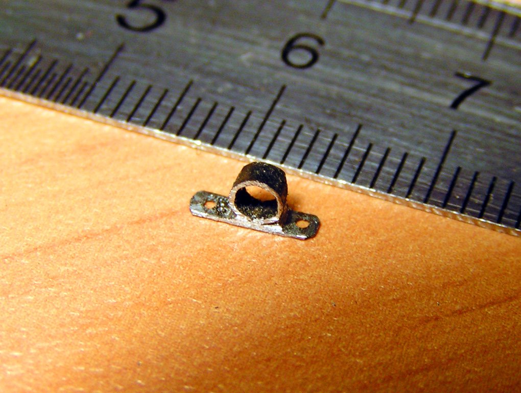
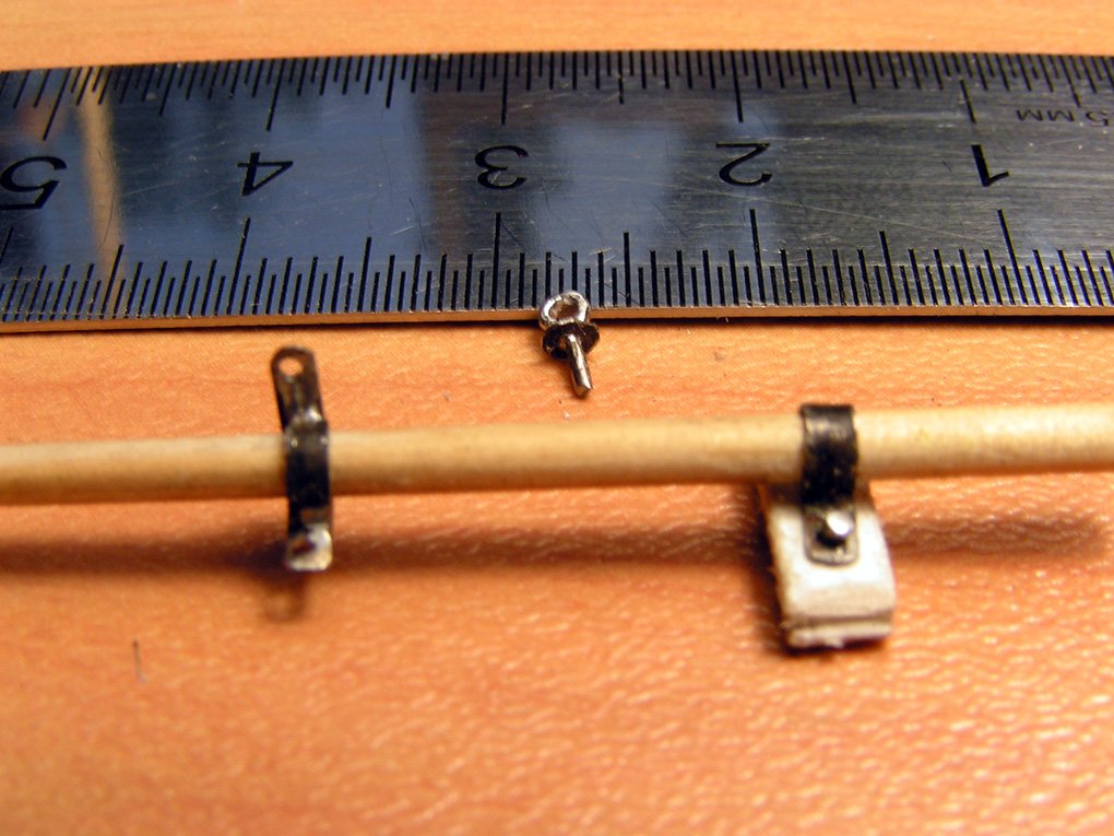
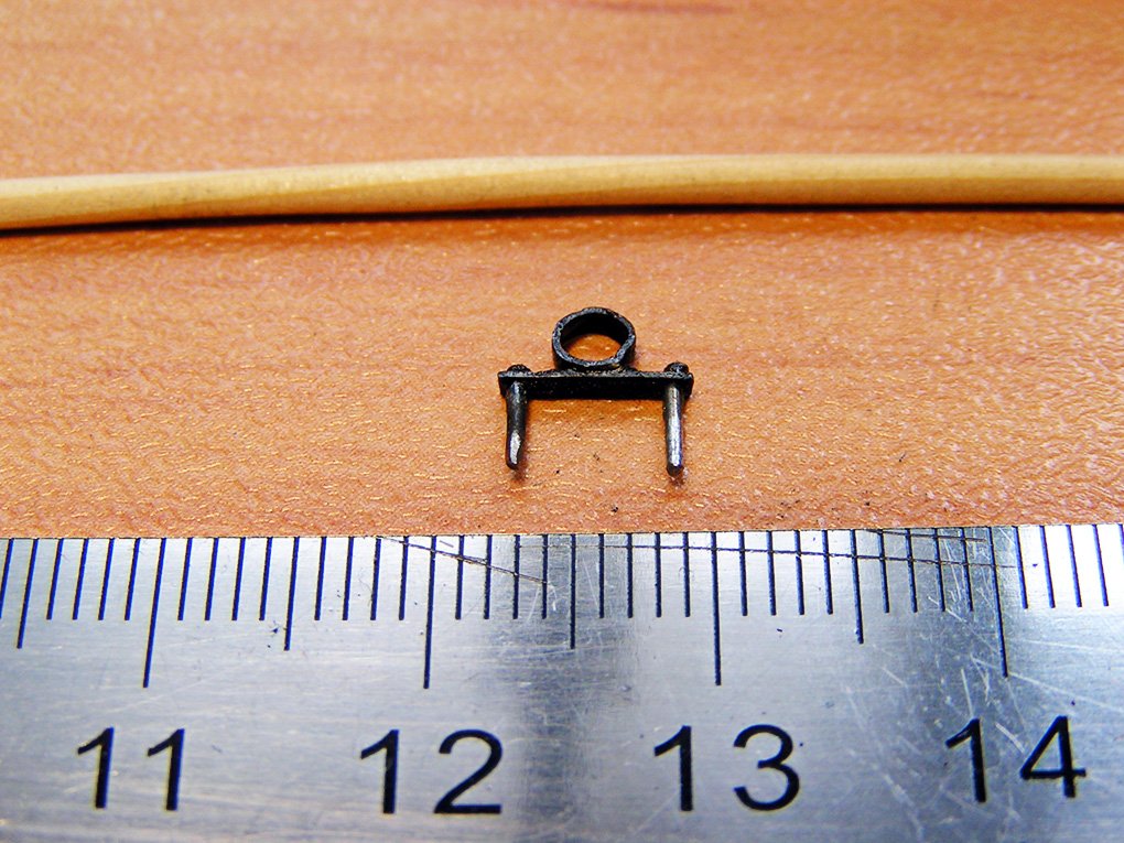
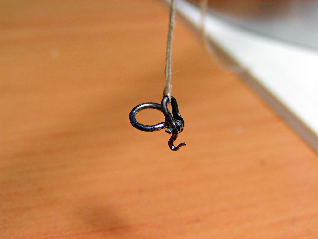
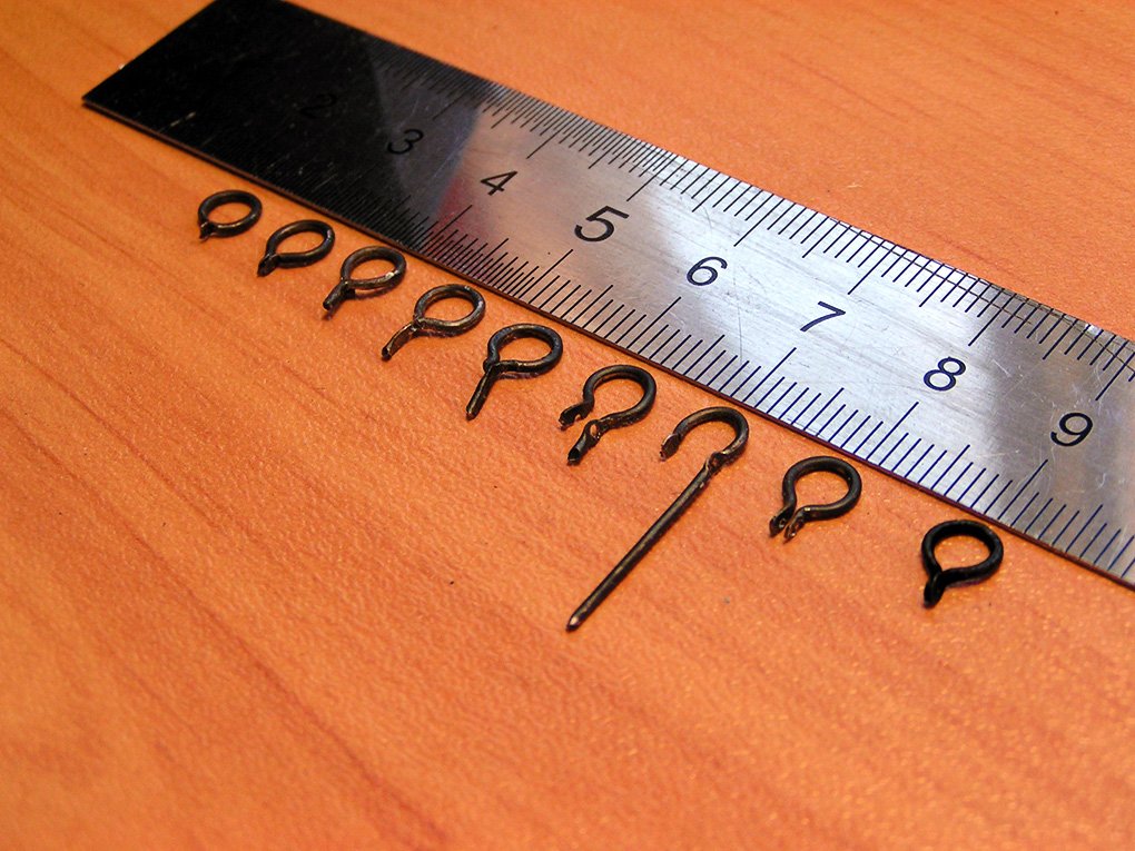
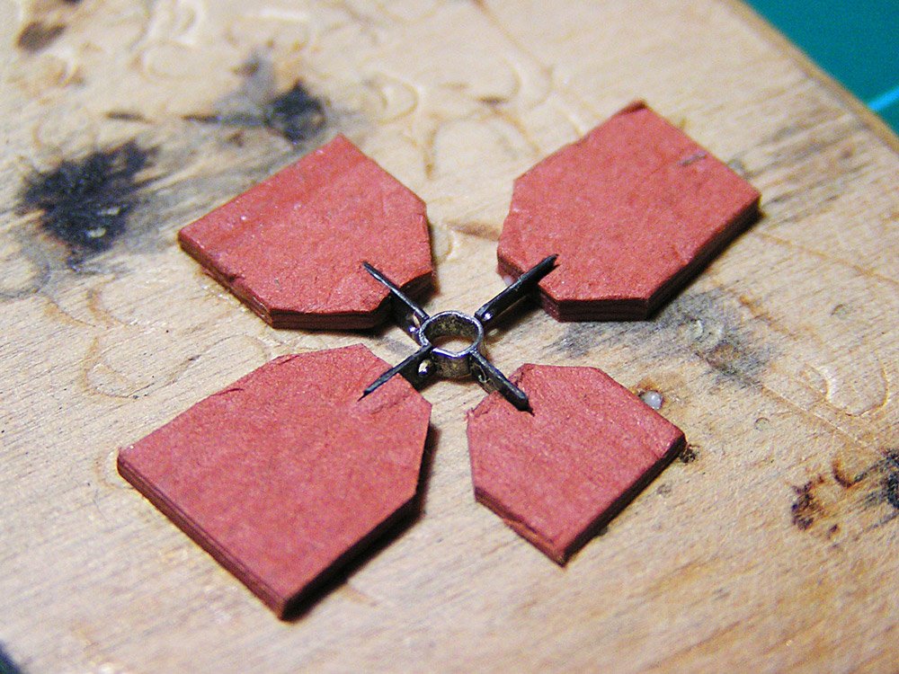
Hello Tony. This is a great assembling and good job! I would like share with you and all modelers my method of metal work. I think the simpler the better. I made all "iron" for my french longboat from a wire from a paper clips. After producting I made all details blacken by fire from Cricket lighter. And other important detail is paper clips' steel wire must be preliminary annealed. All the rest are made by little hammer, pliers, file and vise. Photo #305 shows "species origin". 🙂 I did not get the result right away. It took a several attempts. Assembling and soldering of details is good to do in paper template. See picture #303B.
- 124 replies
-
- 14
-
-
- longboat
- Chaloupe Armee En Guerre
- (and 1 more)
-
Tony, I'm very glad to see your excelent work here. I hope you continue your work after "vacation". Wish you big joy with this longboat model.