HOLIDAY DONATION DRIVE - SUPPORT MSW - DO YOUR PART TO KEEP THIS GREAT FORUM GOING! (83 donations so far out of 49,000 members - C'mon guys!)
×


Captain Al
-
Posts
613 -
Joined
-
Last visited
Content Type
Profiles
Forums
Gallery
Events
Everything posted by Captain Al
-
I've now run into a bit of a measurement problem. I've been working with my mast parts with a bit more stick than I will eventually need. In other words I always planned to cut them to size as a last step. I left maybe 10-15 mm at the bottoms of each stick. So now I'm ready to cut to size and have encountered this problem. The drawings which A.L. provides and the lengths shown on their parts list do not jibe -- for the mizzen top mast (the lower and topgallant are OK). The parts list calls for a stick 192mm in length. When I (as well as my good buddy Boyd) measure the drawing it is only 185. Complicating this is the fact that when checked against the dimensions shown in McKay, the A.L. length (whether it be 185 or 192) is off by a lot. McKays drawings indicate a top mast of 24' 3.5", and after careful math, that would be only 154mm at 1:48 scale. The lower mast also computes to far more length than McKay's real life measurements. I could not find the length of the top gallant in McKay. So what now? My thinking is that since the lower and top gallant seem to match (ie A.L.'s parts list and drawings match) and the top mast is the only one in question vis a vis A.L.'s listing, and since we know that A.L.s scaling isn't very perfect anywhere on the model, not to mention the many typo errors throughout, it seems like the best thing to do is just cut the top mast down to the 185 instead of 192. To leave it as 192 would probably do no harm, but aesthetically it would leave a lot of mast below the trestle tree and look funny. Any opinions? Anyone else find this as they built A.L.'s Bounty?
-
LA, take a look at my posts 207 on page 10 or 11. These are the best closeups I have. There are lots of others on these pages from other builders and you should be able to sort things out from the overall collection. I don't know if you're doing the A.L. kit but I think you are. In that case, you can join me at least in being absolutely confused as to what blocks go where. The parts list for blocks in this kit is not only confusing but I've found there is sometimes no connection between what A.L. says a block is and what you can clearly see on either their pictures or drawings. I'm still wondering if block 417 is single or double cause its clearly both in two different places. I think in one of my pictures you can see that I misaligned the sheave hole in the sprit portion. That's one reason to do it over. The other reason is cause my hearts are stropped very badly; there is no room to reeve them. I'm going to remove most of the blocks, take apart the two sections, fill the misaligned hole, turn that section about 45 degrees and drill a new hole (this time being super careful on its position). As for putting on new blocks, that is going to take more research and consultation. I'm facing the same confusion now with the masts. I have the Peterson rigging book and I'm hoping to use it as a guide.
-
LA, I believe I posted some of my bowsprit further up. I'll check and see. If not I will post some. I'll also take a moment to point out why I'm going to redo the whole thing. So don't just copy anything I show you. Danny, thanks again. I've been thinking of using some real seizing line waxed which I have left from my sailing days but its just too big. And someone once posted that any of the waxed stuff draws and holds dust. Have you found that a problem?
-
Dan, I've been looking closely at your pictures, particularly the last one of post 233 and doing some experimenting with my as yet to be assembled mizzen mast. When you put each each loop or pair of shrouds over the top of the mast, it looks like you've seized the loop into the shroud. Is it easy enough to estimate or measure how big this loop should be and seize it off the boat? Seems easier that looping it over and then seizing it. And as you put on each successive pair do you kindof turn it a degree or so aft to make it line up with the deadeyes on the channel? Would you suggest a bit of watered down pva over the whole pile to keep the loops stacked nicely and in the right orientation?
-
Very good explanation Dan; thanks. I'm going to have to figure a way to keep my top masts and top gallants in perfect alignment while the glue dries at least enough to do it for me. I was looking at Peterson's book on rigging this morning and noticed (not for the first time) the numbering scheme for the pairs of shrouds. I was wondering if there is any reason besides consistency among naval archetects and builders why the starboards are odd numbered and the ports are the even ones.
-
Lots to remark about. Thanks first for everyone's input. And Mike, feel free to usurp space any time. Its good to hear from you and know your actively building. I'll get to the picture posting issue first -- I'm convinced its my browser (IE10 on Windows 8) and if its so easy to download and install Chrome I'm going to try it. I used to use foxfire but gave it up when I got this new computer with ie 10. Now for the real interesting issues. I had to look up lubber hole and found it defined as a hole in the crows nest platform to allow for easy access. And it was noted that it was considered quite unseamanlike to use it instead of stepping around the shrouds to the side of the platform. I don't really see a lot of difference between what CP suggested and Danny's remarks. I thought CP was simply saying make this lubber hole a bit larger. Or maybe the lubber hole CP suggests is an additional hole -- because the space between the inside edge of the platform and the mast is not large enough to work the "jeers" (I hope I'm using that term correctly cause I haven't yet found it defined) through. I probably will opt to do whatever I am able to do. There is a lot of stuff going on up there and I just want to get it to look as good as I can. Which then leads to Mike's question to which I have no comment yet and will await something from someone. I'm still figuring out what blocks and deadeyes go where, so when Mike says the far end deadeye I need to check it out to see which one is the far end and why it is a problem while the others are not. Oh, and Danny, I see where you moved that pic above the text and that is just what I'd like to be able to do. If you had no problem it probably confirms that its an IE issue.
-
Thanks Boyd. I sure wish I could solve this picture adding problem. I've been working on it with Dan's tutorial in a second open tab, reading it step by step as I went. The hangup seems to be that after I upload the picture and then go and place the cursor where I want it to be, and then, I'm supposed to click on Add to Post. So I move the cursor down to that box and click on it. That should add an "attachment code" but it doesn't. Now if I click on submit, I get the picture but its at the end of the post as usual. What are the little black squares at the left margin of the photo supposed to indicate? Can they have any bearing on where the pic ends up? Can they be dragged and dropped? Even after a second edit (like adding this sentence) the picture drops to the bottom. Well now I think I've found a way (drag and drop) to insert a thumbnail where I want it. But the problem is when you click on the thumbnail you don't get a full screen picture. Just a slightly larger thumbnail. And after dropping the thumbnail where I want it I then have to delete the full picture from the post or it shows up twice; once as the inserted thumbnail and again as full blown at the bottom.
-
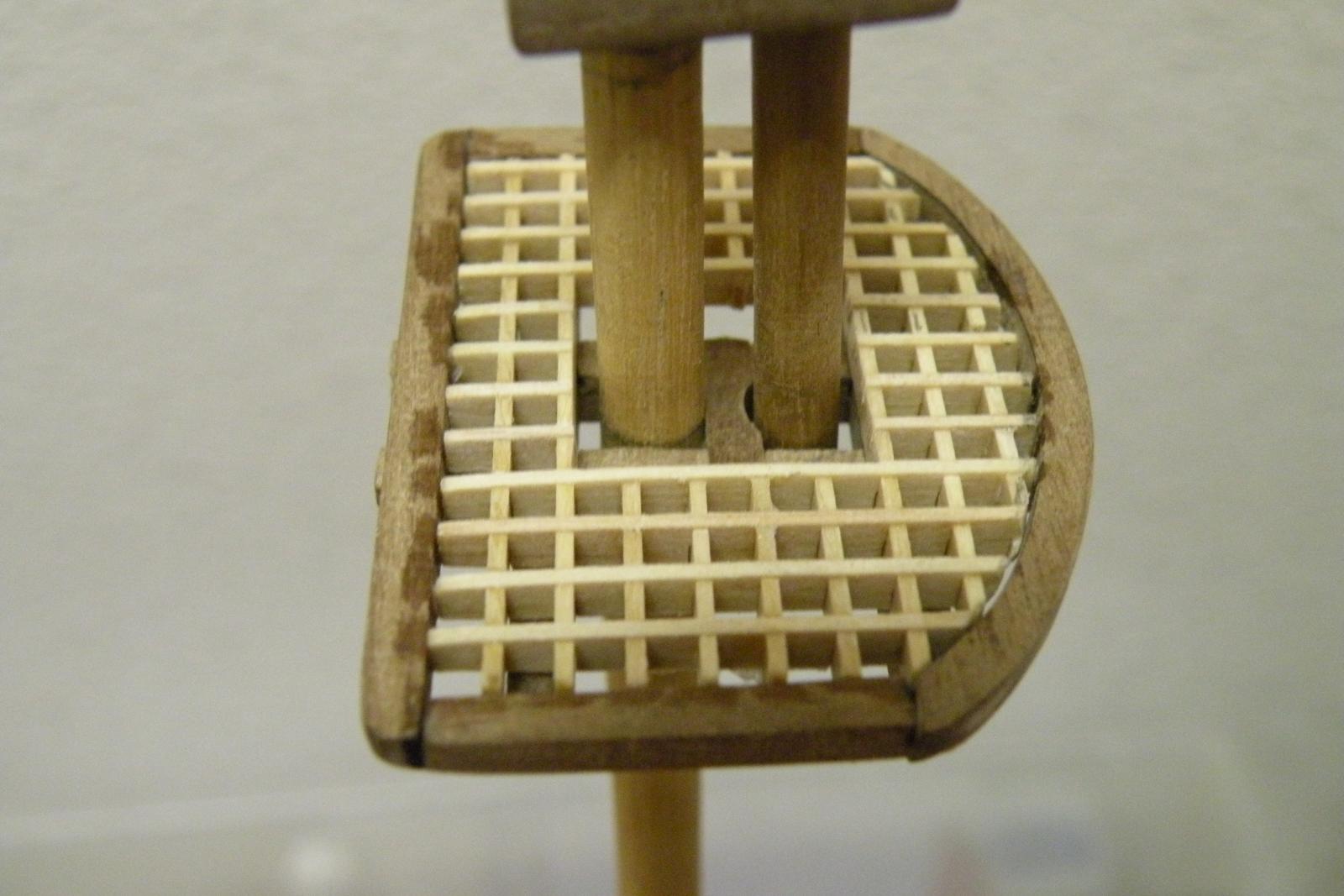
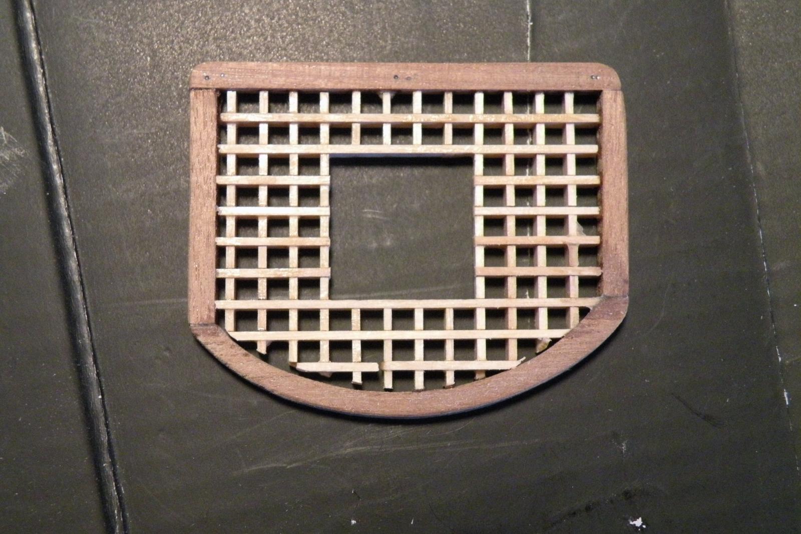
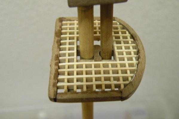
Muchas gracias. Very good tip re. the yard slings. I understand you to mean that I should leave a square of grating open. That's what the red arrow is showing....right? You've been a great help to me CP since you found my build. Thanks for following along.
- 265 replies
-
- 1
-

-
- finished
- artesania latina
- (and 1 more)
-
CP, good advice as to which parts to put on the mast first. I've been contemplating that and until your post I thought I'd put all three parts fully glued together onto the ship as one piece. So you advise against that. I'm only thinking that to get that perfectly aligned top and topgallant sections onto the lower section, through the trees and cap, it would seem easier to be accurate if it were on a bench and I could use a straight edge to align the parts. How would you assure that straight line if I do it on the boat after the lower section is in place? Just eyeball it? There's enough weight on each part that unless I used CA glue (don't want to) I'd have to manually hold it in place til pva dries it otherwise I'm sure it would slump. My joints in the caps and trestle trees are tight for the most part but some have a wee bit of play -- enough that if it slumps it will be seen.
-
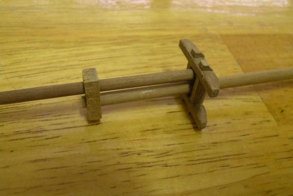
LA, I was confused I guess with your question. I thought what you were saying was the part came with the holes at an angle and you didn't think that was correct. Now I see what you're saying -- or asking. My part was predrilled at an angle correctly. All I needed to do is drill the hole at the top and then bevel off the top and bottom. Sorry if I confused the issue. As for your's, sounds like you got a bad part and to make it right you'll have to do it over with the holes at the correct angle. Use a protractor on the plan sheet to get the right angle and hopefully you have a drill setup that will let you do it accurately and not visually.
-
LA, the holes in the bowsprit cap must be angled for the sprit to point upward while the cap itself is perpendicular to the waterline. You will then bevel the top and bottom surface of the cap so that they are parallel to the sprit. And finally, when you drill a hole for the little stick (I don't recall what its called) it should be angled so the stick is parallel to the sides of the cap and perpendicular to the water line. Now I modify that last sentence or two. Its much easier to drill the hole for the stick first, while the cap itself still has squared corners (ie before you bevel it) and then bevel it. Much easier to drill a 90 degree hole than an angled hole. Hope this answers your question.
-
I'm beginning to think that its my browser or something that just won't let me put captions under the pix. I've followed Dan's directions to a T but it just isn't happening for me.
-
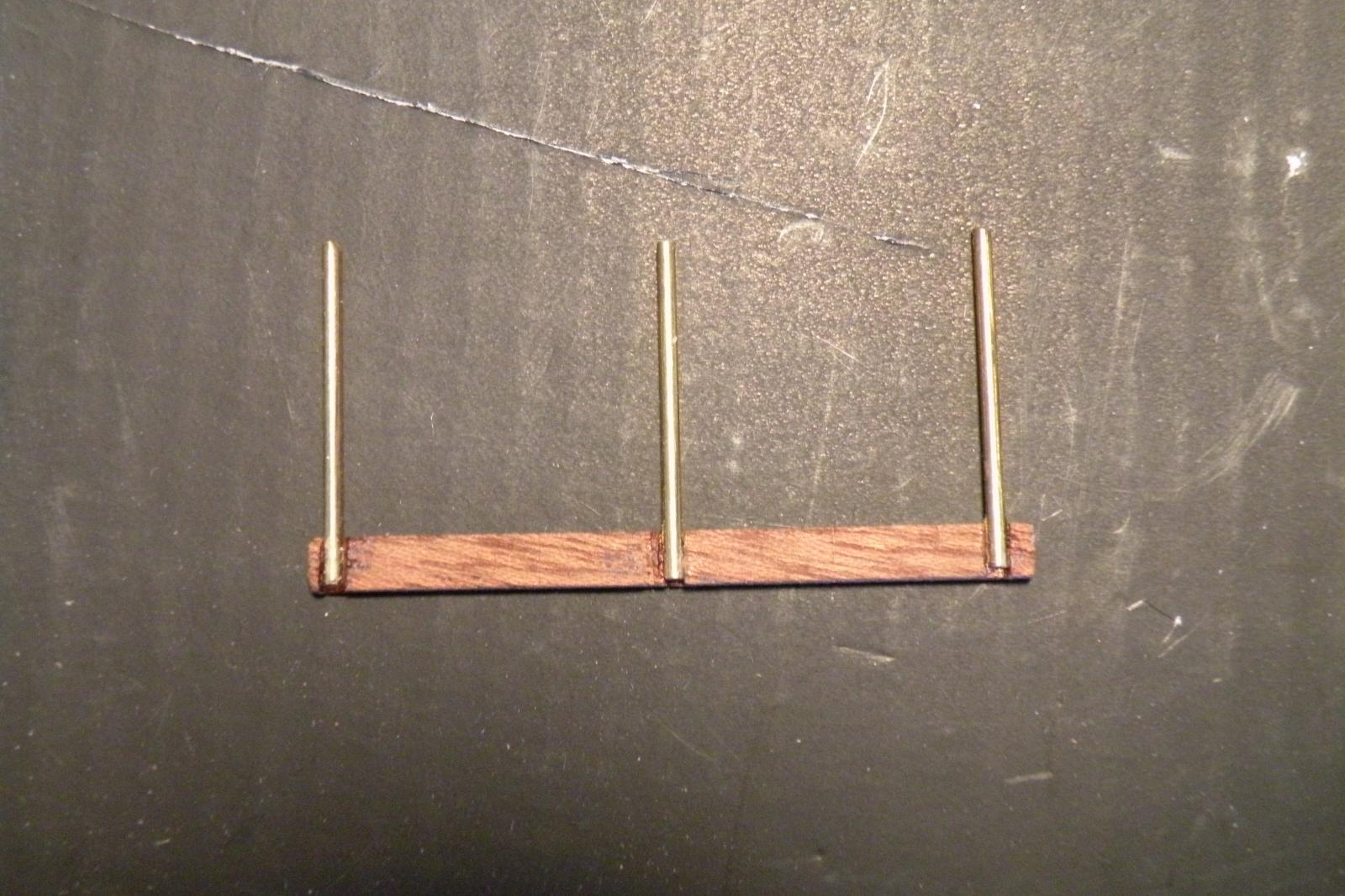
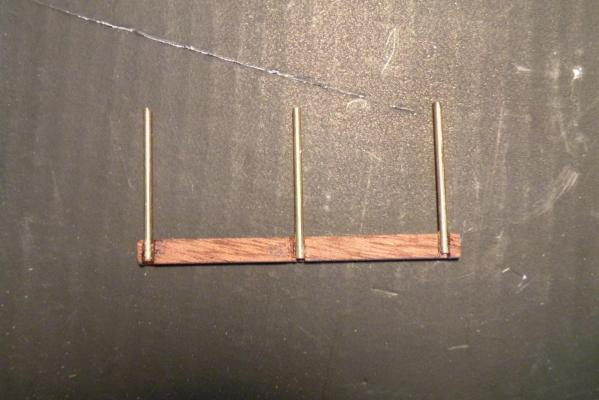
The above photo shows this part 603 with a curve filed into it cause I couldn't get the top mast to sit straight up without it. I also had to file down the top of the spreader to make it flush with the trestle and cross trees. A bit further above in the photo of the railing with its 3 stanchions, note that I mortised the railing for the stanchions to sit in. Add text before or after adding the pic?
- 265 replies
-
- 1
-
-
- finished
- artesania latina
- (and 1 more)
-
So I see I still don't know how to add a picture with a caption except at the end of the post. This will make demonstrating the whole structure rather difficult, so I'm going to do just a bit more and then read Danny's tutorial. I showed the trestle and cross trees for the upper two sections of the mast. The trees for the lower to top connection (parts 592 and 593) and the cap (part 594) are close to identical; just a bit larger. AND, the fact that the trestle tree, 592, has 3 notches. This stumped me for two or three days. Three notches but only 2 cross trees, 593, to go into them. What goes into the 3rd set of notches? Answer: part 603 spreader (which, if you have the A.L. kit and plan sheets will only be labeled on the drawing of the crows nest, so look closely for it).
- 265 replies
-
- 1
-
-
- finished
- artesania latina
- (and 1 more)
-
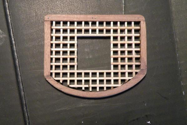
So a month's gone by without an update to the log, so I'll try to catch it up now. To begin, although the last few posts I made indicated that I was going to try my best to get away with that misalignment of the sheave in the bowsprit, I have decided to redo the whole thing. In addition to the sheave hole, as CP pointed out, I put the wrong type of block in some places. Moreover, if you look closely, I think I've stropped my hearts completely wrong leaving no way to actually rig them. So, after I finish my masts I will redo the bowsprit. Now, on to the masts. I've spent the last month working to understand the positioning of each of the little pieces that go into the mizzen. Don't know why I chose to start with the mizzen. Maybe cause its a bit smaller. At any rate, its been 95% of time spent interpreting plans and parts descriptions and 5% fabricating them and dry fitting. I'm going to try now to show pictures of each part and where it goes, and for the sake of other A.L. Bounty builders, I'll include the part number. This is a pic of the top and top gallant sections (parts 598 and 608) held together by the cap (part 607) and the trees (parts 605 and 606). Here's my completed crows nest platform which will sit on top of the trees, 592 and 593. It still needs to have blocks added and 10 holes drilled for rigging lines (of which I don't recall the name). I will also drill 3 pilot holes to insert the bottoms of the 3 stanchions (parts 528) for the railing (part 597). The kit doesn't instruct or show any holes for the stanchions but I think it makes it much more secure. I'm going to stop here cause I don't really know if my pictures and captions are getting into the post at the right places. I'll post this and see how its doing and continue in a while.
- 265 replies
-
- 1
-
-
- finished
- artesania latina
- (and 1 more)
-
You're not the only one confused by the detail of these mast structures and finding no help in A.L.'s instructions. Reading plans is very hard for me but I'm gradually getting better at it. If you hold off a bit on adding those confusing details I will try to update my log specifically on that topic. I'm going to take some pictures (my modelling is better than my photography) and hopefully they serve to show what I believe is each piece and where it goes. Watch for this update in the next couple days.
-
LA, you're certainly making good progress and doing good work. I've been working on just the mizzen mast for two or three weeks now. I agree that A.L. has zero instructions and only one picture of the crows nest (platform) assembly which isn't clear enough to take direction from. But the plans are pretty detailed and accurate and in conjunction with the parts list they can be used to assemble a pretty good impersonation of the Bounty's mast structures. Are you considering your masts finished or is there more that you'll put on? Cause what I've noticed on your pictures is that you haven't put on a lot of the little detail pieces that I've found so time consuming just to figure out from the plan drawings. For example, you haven't put on stiffeners, bolsters (or chocks), spreaders. I may not be seeing them in the pix. Did you decide against them (for a model they don't add anything in the way of strength, only adherence to historical accuracy), or are you going to add them later? Oh, I forgot, are you glued in yet? Doesn't look like it but thought I'd ask. And so you'll add the crow's nest platform and all its blocks and holes later? My plan is to take each mast individually and do one at a time even though there's so much similarity to all 3. That way they'll only get easier. I've pretty much finished fabricating all the pieces for the mizzen and will be assembling it soon (after I restain the lower mast dowel itself). The order of assembly is tricky, isn't it? You have to make sure that parts can slide on over other parts. So thanks for posting these pictures; they help me in what I'm doing. I'll post some on my build log as well and maybe they'll help you with any of that detail work you will (or won't) do.
-
Not much chance of that. And yes, I knew you weren't a stickler for historical accuracy and had your tongue in cheek. Heck, maybe Bligh would have preferred some of you modifications and ordered them installed. Who knows?
-
Drill speeds and materials
Captain Al replied to Captain Al's topic in Modeling tools and Workshop Equipment
Thanks guys. Good information. The one number that surprises me is the 17,000 for drilling that you show Mumin. Do you suppose that's for metal or wood? Reason its surprising is cause my full size Delta drill press which has multiple combinations of spindles for multiple speeds, has a table that shows in the low 1000s for wood (depending on thickness). If its for wood, the 17,000, then my dysfunctional Dremel is going too slow for even wood at 13000. Or maybe its running at 35,000 (its original max speed) even though the speed control says less than 15,000. I'm going to do some additional research. Maybe Dremel's web site has a table. -
Don't think of not putting the jolly boat on the ship as being historically inaccurate. It all depends on when you are looking at the ship in model form. There were many times when the jolly boat (and the launch of course) were not on the ship. If you are presenting the model as how it looked after the mutiny, then the launch would not have been on board. On my build (for various reasons) I chose not to include green breadfruit plants in the pots. My rationale is that I'm showing the ship as it was before they arrived in Tahiti. I don't think anyone would criticize a painting of the Sierras in August by saying "where's the snow?"
-
I'm wondering if there are any references to appropriate drill speeds for the various materials we drill through, such as soft wood, hard wood, brass, maybe even plastics? I assume that after a while experience kicks in and you get the feel for it. As a relative newcomer though, I think I'm burning a lot of my pieces and the bits themselves by using speeds way to high. Note that this is due to the fact that my Dremel has lost its variable speed ability and now seems to be stuck at around 15,000 rpm, so that's the speed I use for most operations -- not only drilling, but grinding and using the cut off wheel. A new Dremel is first on my "to buy" list. This question also comes to mind in those other operations -- grinding and cutting through brass rod and sheet. I'm thinking that there must be some table of values to use for the different combinations of materials and speeds. Maybe thickness comes into play as well.
-
Hey Boyd, as usual a great log and description of all the great work you've done. While my build may have initially been inspiration for you, the shoe is certainly now on the other foot. You set the bar extremely high. I can't wait to see what you have planned for your deck, planking and adornments.
-
Another mystery solved. Thanks CP. I have both those books now.
-
Part of my problem with the dowels fitting the holes correctly was due to the fact that I had the cap backwards -- I thought the square holes were to go at the bottom of the next mast part and the round ones at the top. Once it was confirmed to me (by Danny no less) that the square tenons were at the top of the masts, then these size dowels worked better -- but still not perfect. Lots of adjustment sanding will be needed for perfection. Its also tricky to make sure they are the correct diameter to slide through the trees. Thanks for posting these pictures CP. A question: Are those half round parts which the kit calls "cap stiffeners" and which are placed on top of the cap in between the top mast and the top end of the lower mast -- are they supposed to simulate sheaves for halyards? All the photos I've seen of them seem to show grooves in them or even the halyards running up and down around them. And yet they're called "stiffeners."
-
Welcome GG to the A.L. Bounty club. I'll be watching your build and maybe from time to time can offer some good advice. At this point all I can add is that you've gotten great advice from the others and I agree with it all.