vossiewulf
-
Posts
1,477 -
Joined
-
Last visited
Content Type
Profiles
Forums
Gallery
Events
Everything posted by vossiewulf
-
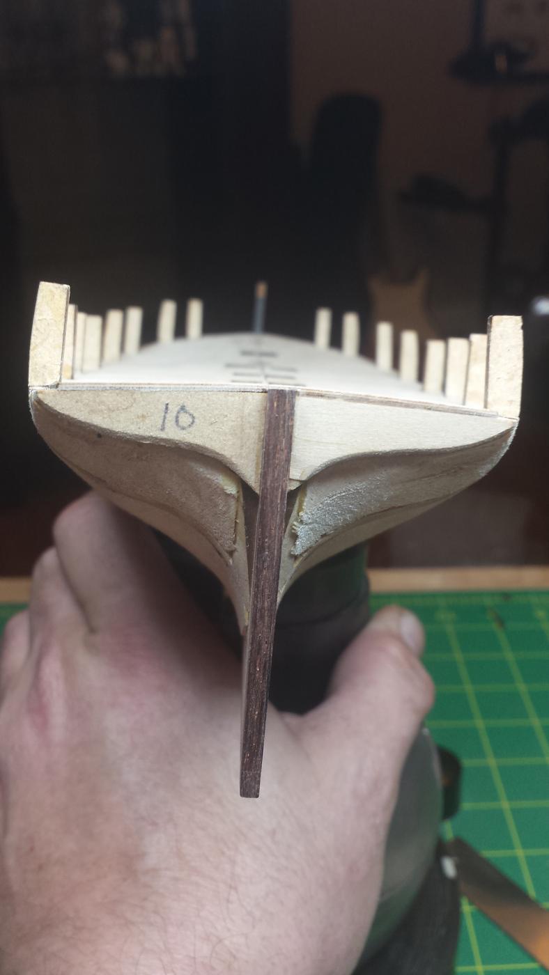
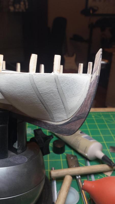
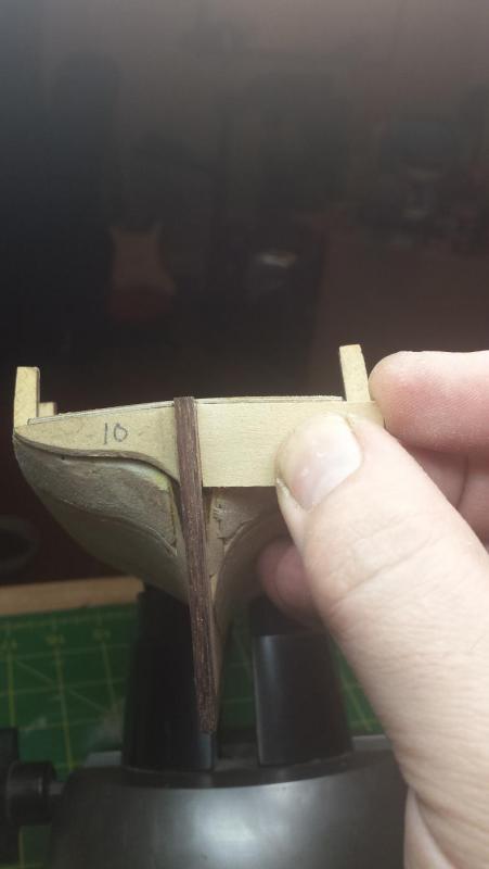
 The plankling is really confusing me at the stern in that I can't understand how the kit instructions are supposed to work out correctly. You're supposed to put two layers of planking on each side of the deadwood going into the rudder post, which = 4 x .047" fitting flush with a piece that's .115" wide. Not only would you have to remove the entire deadwood you'd be running planks from one side against planks from the other. My plan, and in the spirit of trying not to solve every problem myself, please tell me if I am smoking crack. is that I will have two bearding lines and two rabbets at that end. The first bearding line is basically what I have now, and I'm going to make the rabbet for the first run to stop as far short of the rudder post as possible and I'm going to fair the first layer into the current false keel surface. Then we'll work from that second bearding line to cut a .040" or so deep second rabbet up against the rudder post. I'm not seeing any major issues on the rest of the hull, except that the width of the keel at the very top of the stem becomes really narrow with two layers of planking eating up the available space. And also the twist that needs to be put in the wales planks are about 70 degrees, which should be interesting. I also need to stop on the planking to remake the top piece of the stem in cocobolo and I'm making it in three parts so it will be much much stronger. Hopefully that will give enough time for you guys to report back on my crack-smoking status.
- 714 replies
-
- 2
-

-
- lady nelson
- victory models
- (and 1 more)
-
Yep, I was aware of that ship too but not that people wanted to defend its honor
- 714 replies
-
- 2
-
-
- lady nelson
- victory models
- (and 1 more)
-
That was my original plan, but the kit calls for the keel to be installed since it has that weird U-shaped piece up front that is needed to retain the upper bulkhead strip that is the first piece (according to the kit) to be installed in the planking process, and they want you to work down from the top. Even so, if I had it to do again I'd probably figure out a way to make a temporary piece to hold the bulkhead strips and leave the keel off until the end.
- 714 replies
-
- 2
-
-
- lady nelson
- victory models
- (and 1 more)
-
I was laughing thinking about that, it would be perfect for a sailing comic - show ship from outside with that happening and a text bubble above with "uh, Captain?"
- 714 replies
-
- 2
-
-
- lady nelson
- victory models
- (and 1 more)
-
Well that's an amusing way to solve the naming issue, I was thinking also that that seemed to be a name that wouldn't exactly thrill the one-armed guy.
- 714 replies
-
- 2
-
-
- lady nelson
- victory models
- (and 1 more)
-
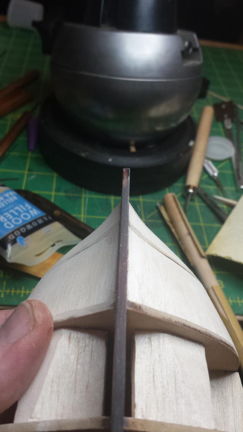
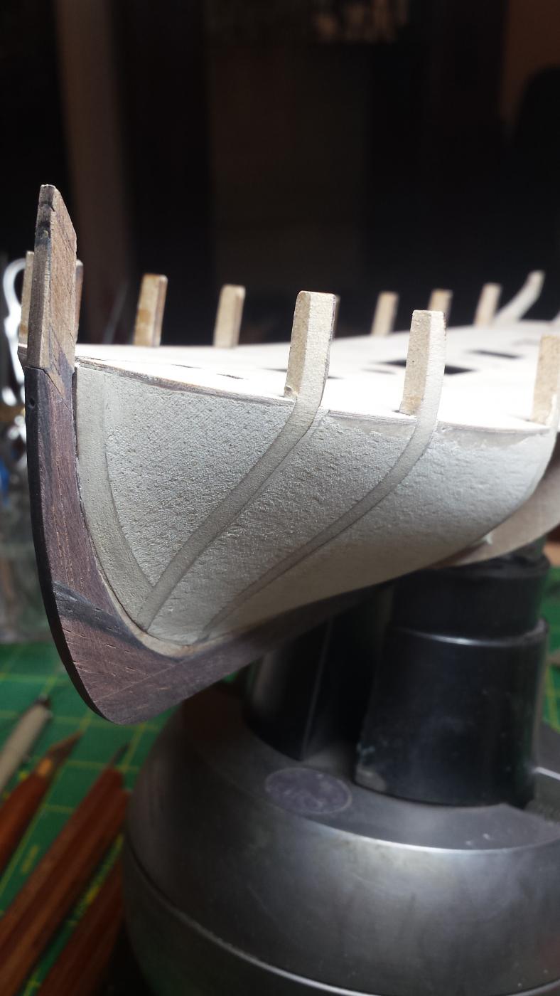
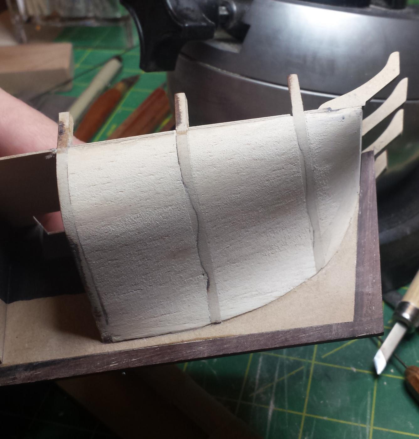
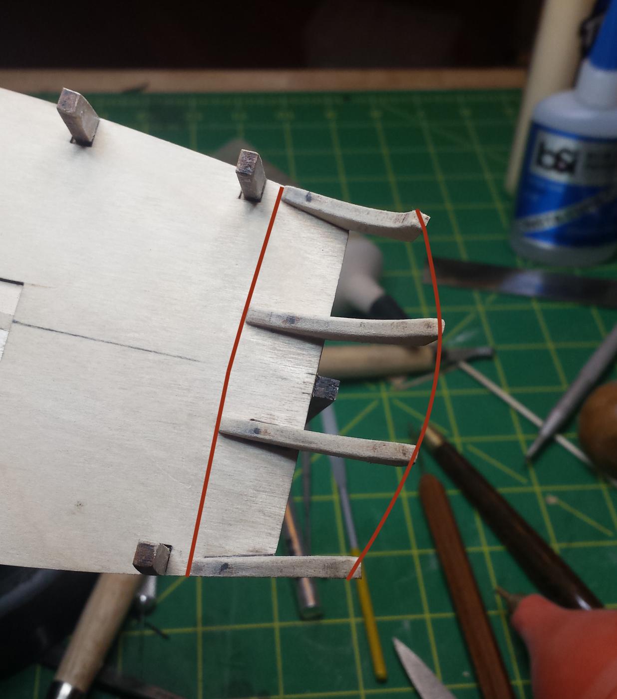
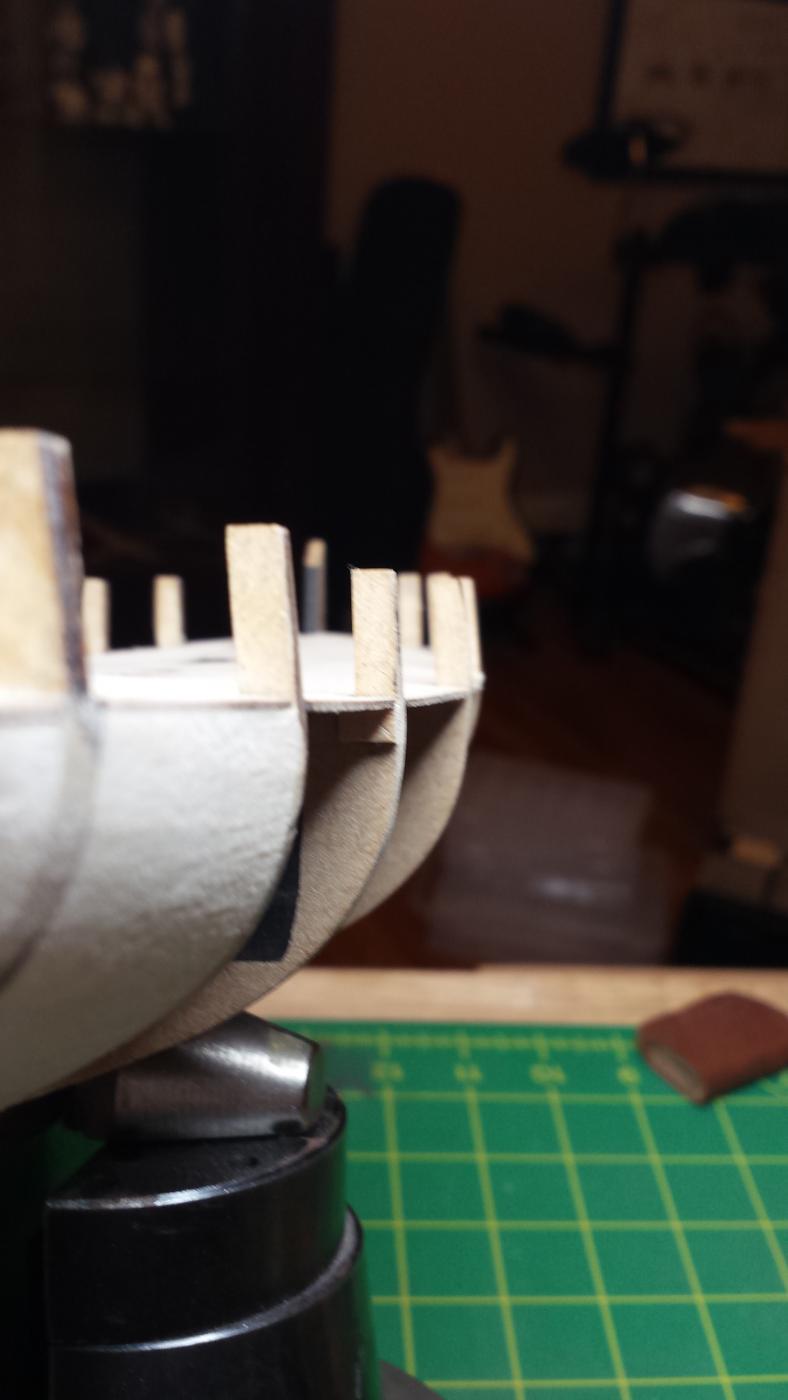
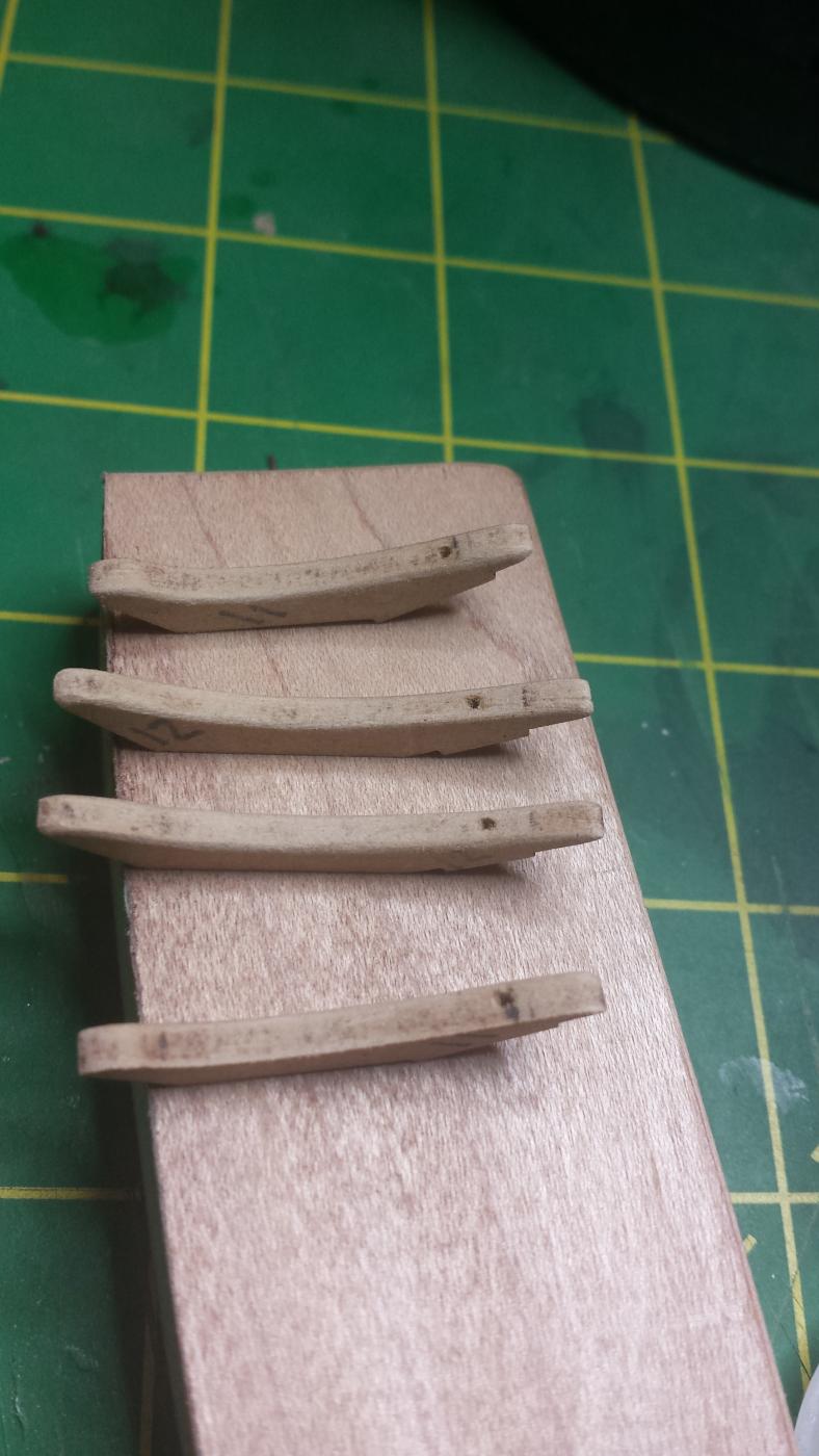
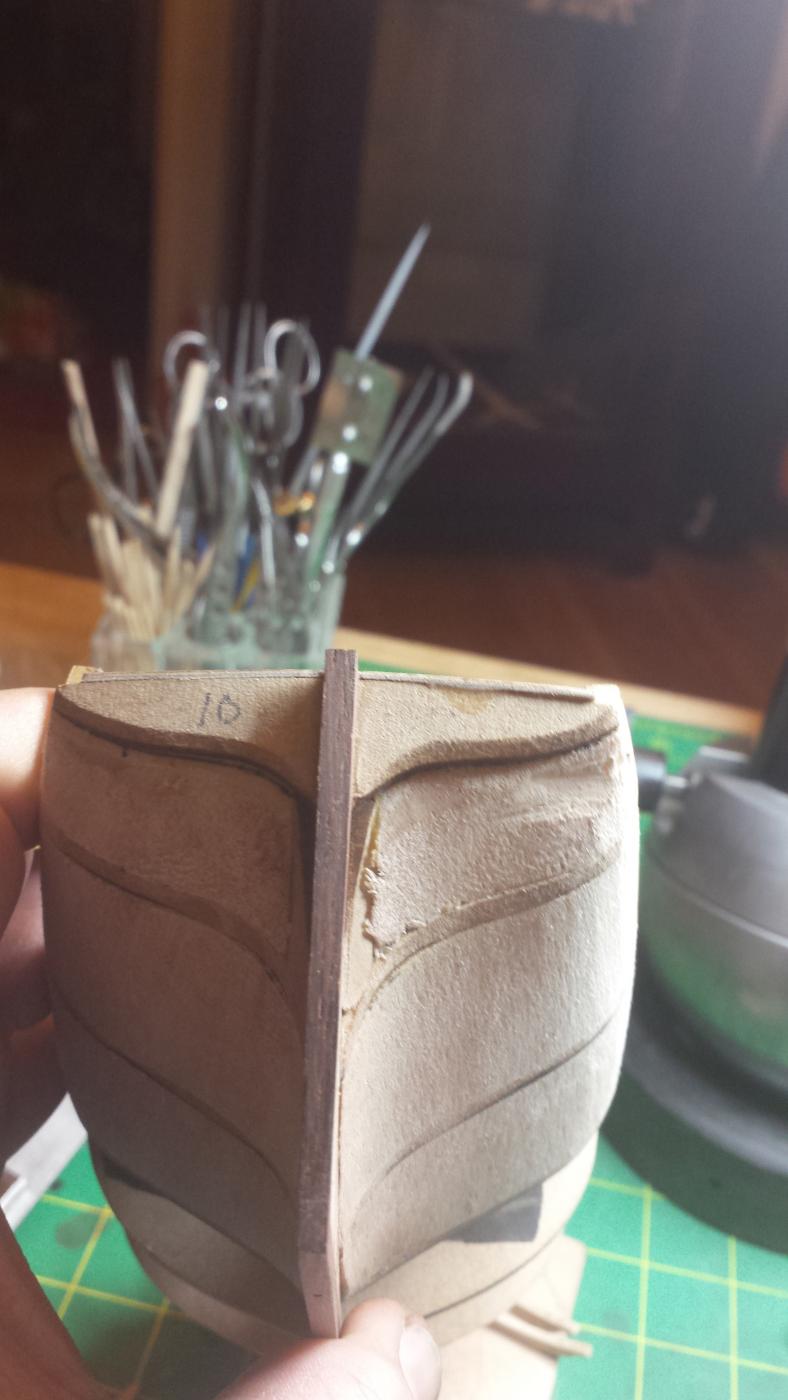
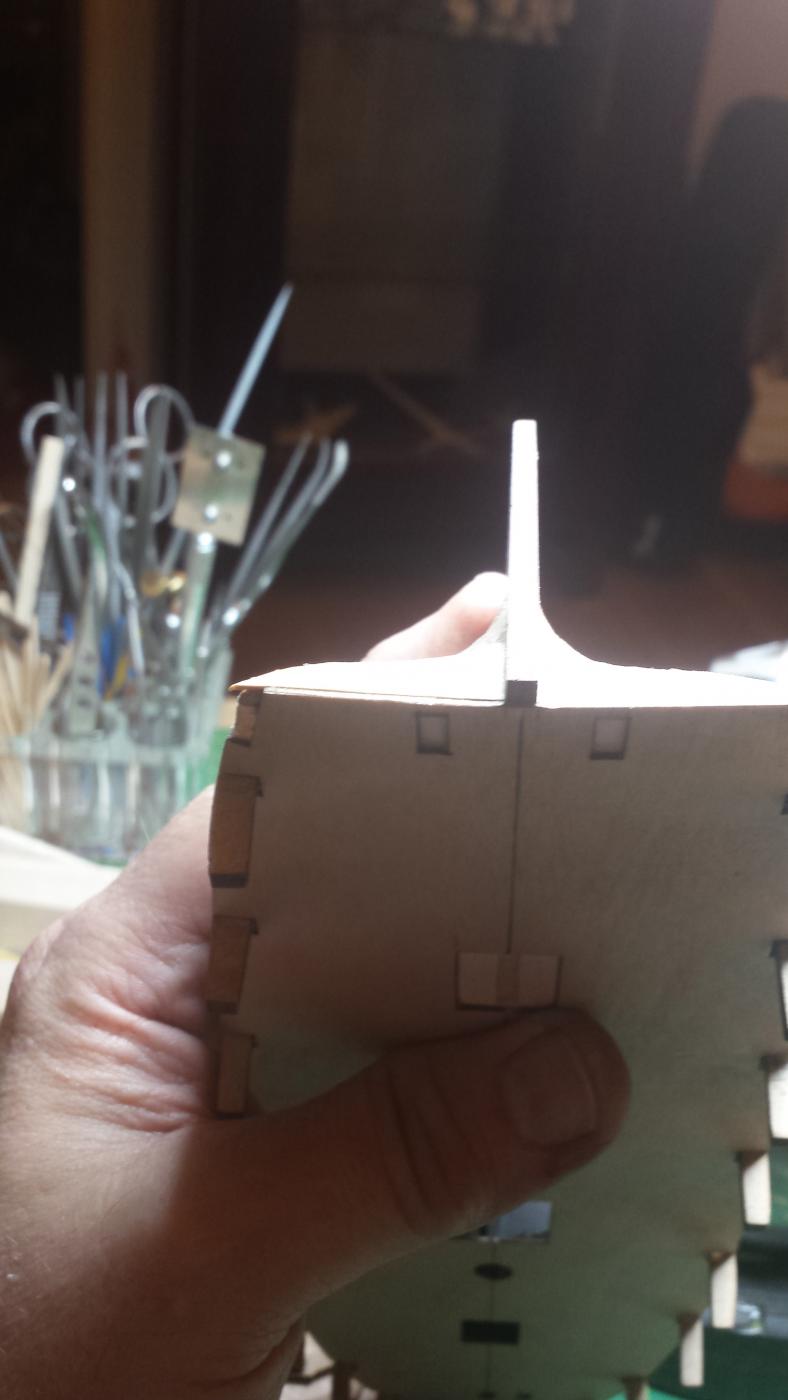
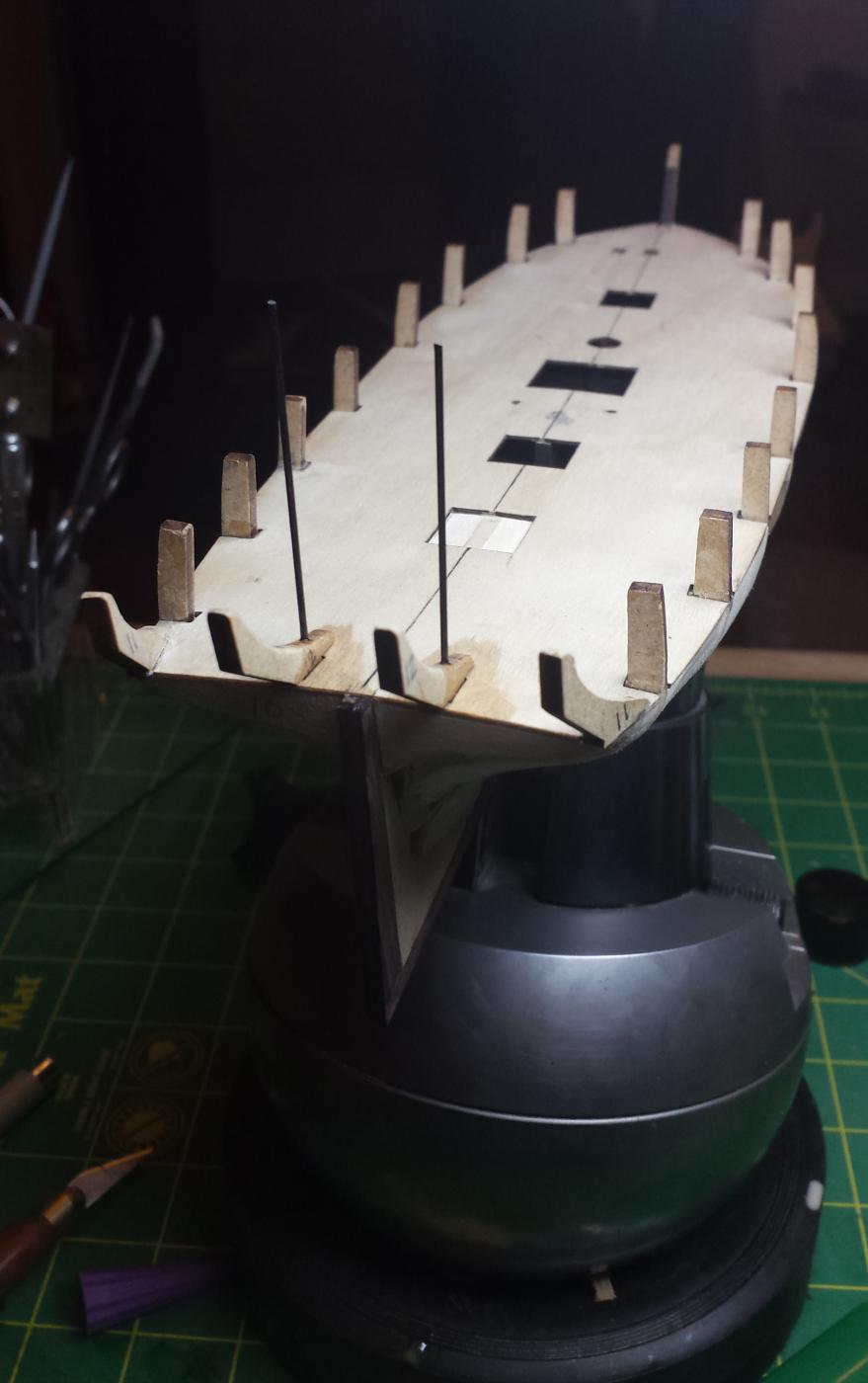
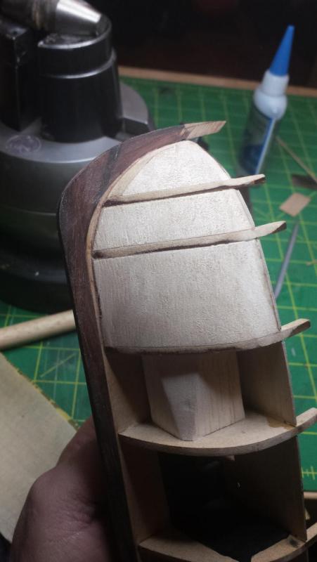
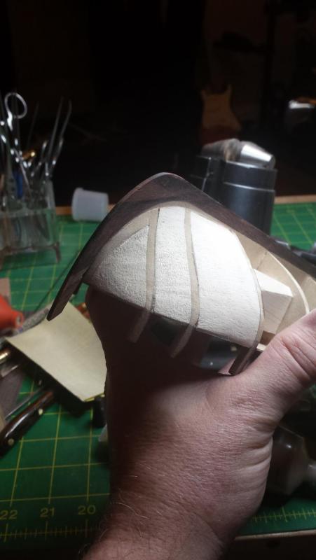
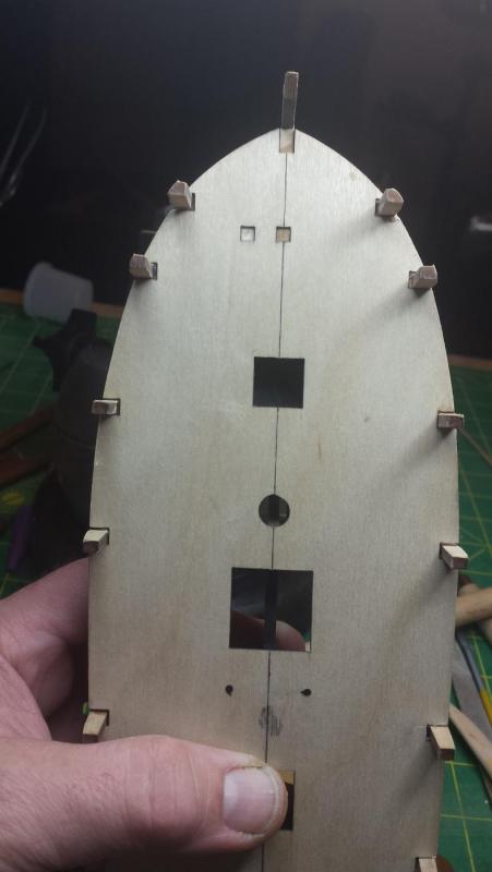
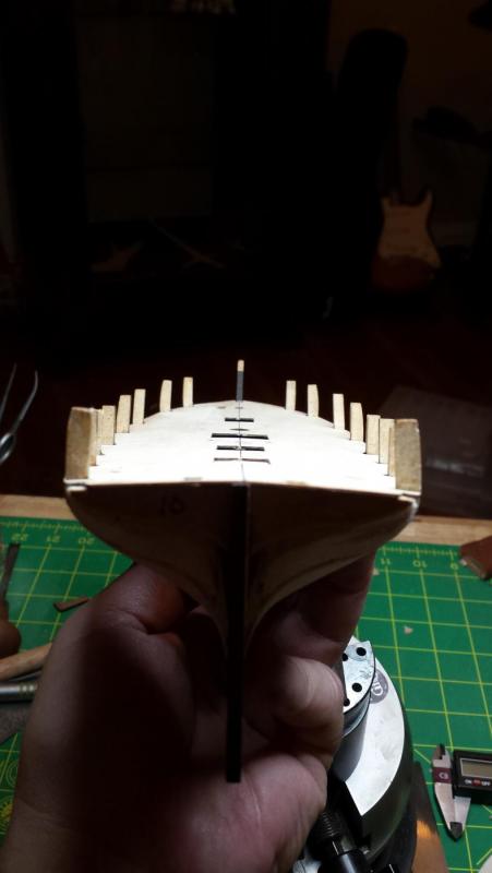
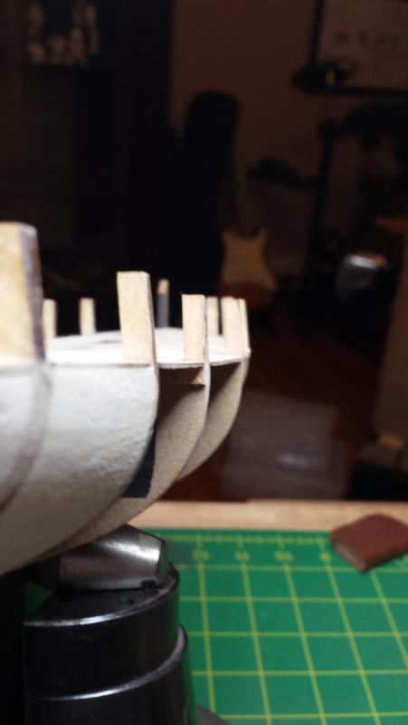
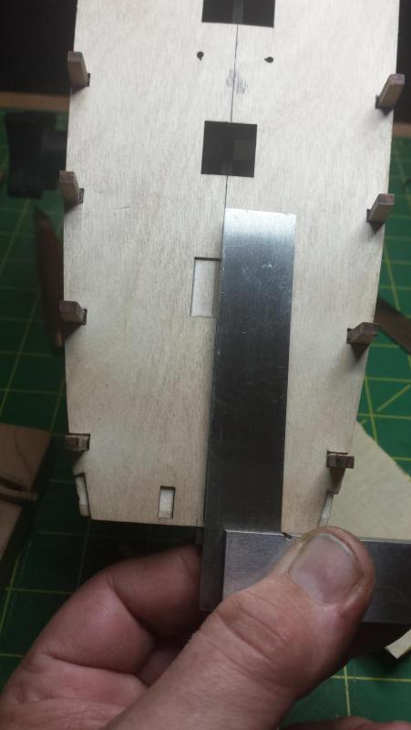
Hull is now fully prepped as far as I can tell, all I need to do is cut the rabbet for the first layer of planking and then add the upper bulkhead strips and start bending wood. This is someplace I have to go back and read Mr. Underhill I think, but as far as I can tell I'll need separate rabbets for the first and second layer of planking, the first stopping well short of the rudder post. It would pretty much have to since two layers of that planking are .090" when the whole rudder post that started as .125" and is now about .115" after level sanding (I was fine with that, only lose .002 final sanding). And 2 x .090" > .115" if I remember my arthimetic. Or not cut a rabbet at all for the first layer and just bevel the ends but I don't see how that doesn't result in planks popping out in the long run. Anyway, I had left hull in the just short of done state. In particular upper bulkhead stanchion things have hardly been hit. And here we are after rough sanding. Checking tops of stanchion things to verify symmetry. Bow and stern bulkhead symmetry. . I then hit it with Famo Wood filler for the last gaps, this was really needed on the stern just short of the counter... no it's not the counter it has some other name I can't remember, last frame before the overhanging stern part starts. Anyway the vertical turn there is severe and that bulkhead should be much taller to allow contouring the full edge surface, I only got to about halfway before I decided I wasn't taking that bulkhead down any farther as it was looking plenty small already. Even here the turn from the builkheads to the hull planking seems very severe. Here are bow and stern both sides after final sanding. Overall I'm ok with it as long as I can figure out the rabbet correctly. One other concern is this, these pieces are aligned correctly and are aligned with each other in the front (slight curve from this angle), but the stern ends seem to need much more curvature for full-width bevel than the kit pics show, and only way to reduce it will be to remove material from the center ones. And since I need to think on two things (rabbet and stern) I called it an evening there.


- 714 replies
-
- 5
-
-
- lady nelson
- victory models
- (and 1 more)
-
I agree Tony, like I said it's just a thing I prefer to do, but it's not a requirement worthy of risking a project, so I'll read what I need to. But I'm also still sure that you'll understand something that you figure out on your own much better than you'll understand what you're doing and why when following someone else's recommended steps. A good analogy is Western vs. Japanese woodworking education, here we sit people down and pour knowledge into their heads and then tell them to go try that. There, traditionally apprentices would not only not have that explanation, they wouldn't be allowed to ask questions. They had to sit and watch the master until they themselves had the light bulb go off over their heads as to why the master does it that way. As a result they understand why something is done a certain way as close to figuring it out from first principles as possible. IMO the western method gets people operational faster, but also significantly delays deep understanding, and lots of people taught this way will never have a deep understanding, they just know this is how you do it and they repeat it until they get good at it. I enjoy the experience of trying to solve issues from first principles so I try to do things that way when I can. But I know when I can't and unfortunately this is (tragically because there are some seriously fun challenges here) not one of them.
- 714 replies
-
- 4
-
-
- lady nelson
- victory models
- (and 1 more)
-
I think it says up in my introduction, but I'm in Silicon Valley on the peninsula side. I work at the Visa HQ in Foster City.
- 714 replies
-
- 2
-
-
- lady nelson
- victory models
- (and 1 more)
-
Ah ok, now I understand. And yes that's not a bad idea either, but as you mention you have to decide that ahead and build anticipating that solution, you're basically using what 3d modelers call global illumination or more specifically radiosity, which are ways of simulating how light reflects off surfaces and indirectly lights other surfaces. I've worked professionally as a modeler/animator and keep up with it as a hobby, I tend to think of all lighting issues in those terms. The important thing you need for that as you mention is 1) space for the light to go into and 2) strategically placed high albedo surfaces that reflect a goodly portion of the light that hits them diffusely to other surfaces.
- 714 replies
-
- 2
-
-
- lady nelson
- victory models
- (and 1 more)
-
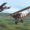
Fokker Dr.I by Torbogdan - FINISHED - Model Airways
vossiewulf replied to Torbogdan's topic in Non-ship/categorised builds
Remember the Oberursel UR.II is a license-built copy of the Le Rhone 9J. Until you get the book, google those and you'll find some good photos. -
Fokker Dr.I by Torbogdan - FINISHED - Model Airways
vossiewulf replied to Torbogdan's topic in Non-ship/categorised builds
He's Swedish and an airline pilot for one of the major carriers as I recall. You should look him up, he's based someplace in Sweden and has a D.VIIF now along with a series of other aircraft he's built. -
Fokker Dr.I by Torbogdan - FINISHED - Model Airways
vossiewulf replied to Torbogdan's topic in Non-ship/categorised builds
Get this version of that book. Getting a bit pricey as it looks like both are out of print, so don't delay. There's a similar book on the D.VII that you should also get if you intend to try a DVII. You should also be able to find copies of them at Abe Books. Also, the best WWI aircraft plans are from Jim Kiger who lives over near me, I bought his entire WWI Aero collection plus I have a complete set of his plans in 1/16th scale for future use. They are so detailed that you can and several people have built full-sized accurate repros from thiem. Jim is also shutting his business down soon as he's in his 80s, so it's also time to buy these if you have an interest. Edit, sigh, first link I put in was wrong, amending. -
Thanks Rick, also noted for future reference. I'm going to tell Chuck that I think he's missing out on a lot of sales, if he offered all those detail goodies for the Cheerful at 1/64, most of the 27 guys currently building would probably buy them all.
- 714 replies
-
- 2
-
-
- lady nelson
- victory models
- (and 1 more)
-
First, thanks Tony, the pics are awesome and are bookmarked for reference. As for reading build logs, I guess it's unavoidable with ships. When I'm doing something new I much prefer to learn the minimum required to be in the ballpark, and then figure out my own solutions for what I need to do. It's part of the fun. I find it also speeds understanding of why certain things are done in certain ways. My intent was to very much enjoy reading said logs AFTER I finished mine, would be very fun to be surprised at all the solutions and compare them to what I came up with. But there are just too many things I need to know and learning them also means learning how people do them.
- 714 replies
-
- 5
-
-
- lady nelson
- victory models
- (and 1 more)
-
Fokker Dr.I by Torbogdan - FINISHED - Model Airways
vossiewulf replied to Torbogdan's topic in Non-ship/categorised builds
One more present for you - a full scale, fully production-accurate Fokker Dr.I with Oberursel UR.II rotary engine built my Mikael Carlson, being flown to its absolute limits. Until 2009 no one had seen that since 1918. And I'm not kidding, watch as he enters the first barrel roll into split S at 0:45, he's too slow on entry and it stalls and departs into an incipient spin all of 300 feet and he does a very quick and amazing recovery to keep from dying. He loads at least 6Gs on at one point too in a high speed max turn over the crowd. He's also built a production-accurate D.VII now. Mikael Carlson flies the Fokker Dr.1 -
Fokker Dr.I by Torbogdan - FINISHED - Model Airways
vossiewulf replied to Torbogdan's topic in Non-ship/categorised builds
Other finish things- first if you decide you must do Richthofen, he flew at least six different Dr.Is, only two of which were all red - the rest mostly had tail and upper wing red but the rest was left in the standard streaky green/brown. He was quite successful in 152/17, that would be my choice for a Richthofen Dr.I. Also if you see World War I in color they have a nice video of Richthofen getting ready and then departing in an all-red plane. Not only was that plane not red, it wasn't even a Dr.I, it was one of three F.I prototypes Anthony Fokker took to the front for combat evaluation, one each went to Richthofen (CO Jasta 11), Werner Voss (CO Jasta 10) and Adolph Ritter von Tutschek, who was the CO of Jasta 12. It's not hard to know this since they film Richthofen standing next to the markings on the fuselage that says Fokker F.1 102/17. The film was made by Anthony Fokker, he wanted a film showing Richthofen climbing happily into a triplane, he then took the film around to other units and showed it to them so they would start requesting Dr.Is. That would be an interesting thing to do, model the F.1 instead of Dr.I. Differences were visible but fairly minor, the leading edge of the tailplane was curved rather than straight like the Dr.I, the aileron balances had a somewhat different shape, and there were no wooden skids on the lower wingtips like the Dr. I. Those were added after testing because it had relatively tall and narrow landing gear and were notorious for ground looping, and the skids prevented most of them from requiring actual repairs. Tutschek's was 101/17, and Werner Voss was killed in 103/17 in an epic 20 minute dogfight, him alone vs. 6 aces of No. 56 squadron SE5as, McCudden called it the most masterful flying he had ever seen. Here's something quite close to what I believe 103/17 looked like, and I've been in more than one argument about this. In fact you can pretty much start a bar fight at the Aerodrome instantly by walking in and saying "HEY GUYS IM NEW AND I THINK VOSS' COWL WAS YELLOW". Seriously, violence ensues. The F.1 prototypes were painted overall in the standard German underside light aqua blue, and then covered with a streaky green'brown like Dr.Is but with a much, much thinner paint that turned it into more of a wash than a layer of paint. McCudden called it "silvery blue" and other No.56 squadron pilots all called it blue green. The reason for the bar fights is the photo below, the other cool thing about 103/17 is this face Voss had his mechanic paint on the cowling. Now the cowlings for 101 and 102/17 were green, and this certainly looks green. However, in WWI they used orthochromatic film that often turned what was known to be light yellow into a very dark color like we see here And when his unit flew Dr.Is they did so with yellow cowlings, but that was after his death. It was odd enough that he painted a face on a combat evaluation aircraft, it would be downright odd to start customizing it with your unit colors when the manufacturer is taking it back next week Also Voss' mechanic said he didn't remember doing anything but painting the face. And here is every known photo of 103/17. Another very good one to do would be Josef's Jacobs' witch of the north Dr.I. He has the most kills by far of any pilot in Dr.Is and flew it longer - he operated his with 130hp Clerget rotaries from Sopwith Camels along with British propellers, which made it probably 4 or 5kts faster than a standard Dr.I. He had all the troops near where he was station looking for engines and props, offering a case of champagne for undamaged versions of either. He had a D.VII in the same markings, he would take that if they were going to be operating above 10k or so, at low alts he continued to take his Dr. I and would be a sole triplane leading a flight of D.VIIs. -
Thanks Tony and Rick And Rick I agree with you, slab sided doesn't make much sense. Also according to the fore and aft rigging book, it was also the location for the ship's bell and some other details that I don't think are in the model, will have to see what I can do improving that. Pat, thanks. And yes I agree, extensive effort on infrastructure makes everything following easier. However I'm not sure what you mean by painting entry spaces pale gray/blue Can you explain?
- 714 replies
-
- 2
-
-
- lady nelson
- victory models
- (and 1 more)
-
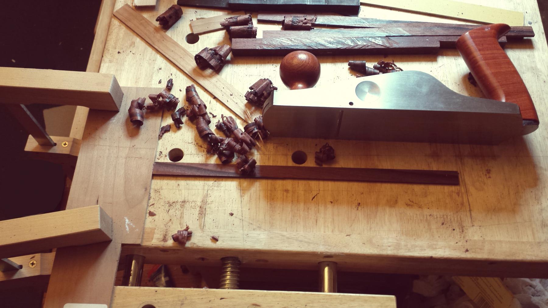
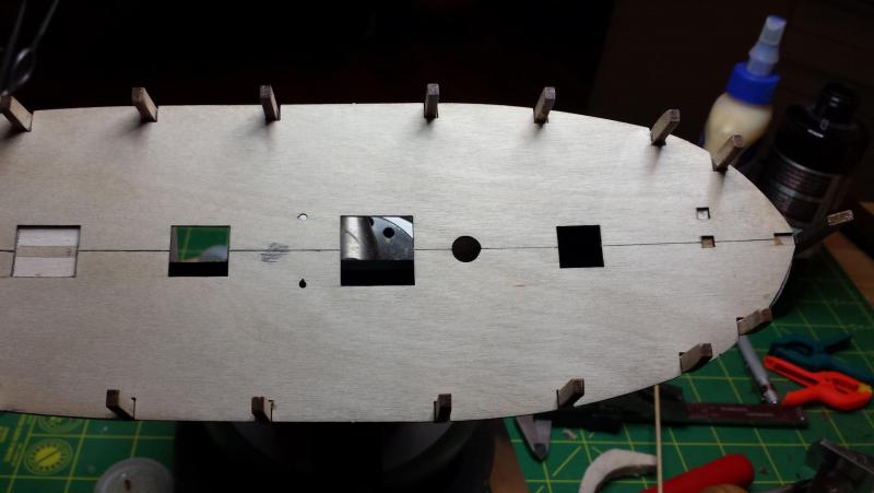
Thanks Popeye. I have three gratings and a binnacle-looking thingy, no stairs. Which makes no sense how the hell do you get to the hold? I just looked at Chuck's Cheerful to see if that would explain and it doesn't, at least not within the time I have allowed to read right now. Only thing I can figure is that one or more of the grates are covering ladders down. Rick, do you know where the hell the stairs are? And next step is final fairing of the hull now that I have all the relevant pieces in place. I think I'm ok with it now, only confusion is that the turn between the second to last and the last bulkhead is so severe vertically that it looks like I would have to remove half of that last bulkheard fairing it at the angle it seems to want. As for the wood, I just stop by Woodcraft every couple of weekends and I almost never leave without buying a couple 2x2 or 1x1 turning blanks that are usually 12" long and maybe some pen blanks too, depending on what they have that week. They're like $10 to $20 and I make all sorts of stuff with them but a single 2 x 2 cocobolo piece will make lots and lots of ship parts, so I recommend doing the same if you have a Woodcraft local or a lumberyard that has a good stock of exotic turning blanks. And I've honestly never seen a piece of non-pretty cocobolo, and as for workability, well, it's easier than ebony. And thanks everyone for the tips and advice, all very helpful.
- 714 replies
-
- 3
-
-
- lady nelson
- victory models
- (and 1 more)
-
I agree, I've been having to fight the urge to fill in the whole thing with balsa or if I had enough patience even better would be basswood to give it more strength, balsa is so easily crushable on the side grain. Maybe the best combo of time and strength would be to rotate the balsa blocks to present endgrain to the planking. Anyway, yes, I'm not sure how you can get correct lines between bulkheads without using a bender to just burn the whole length of the required curve in ahead of time and then just tack glue to buklheads.
- 714 replies
-
- 3
-
-
- lady nelson
- victory models
- (and 1 more)
-
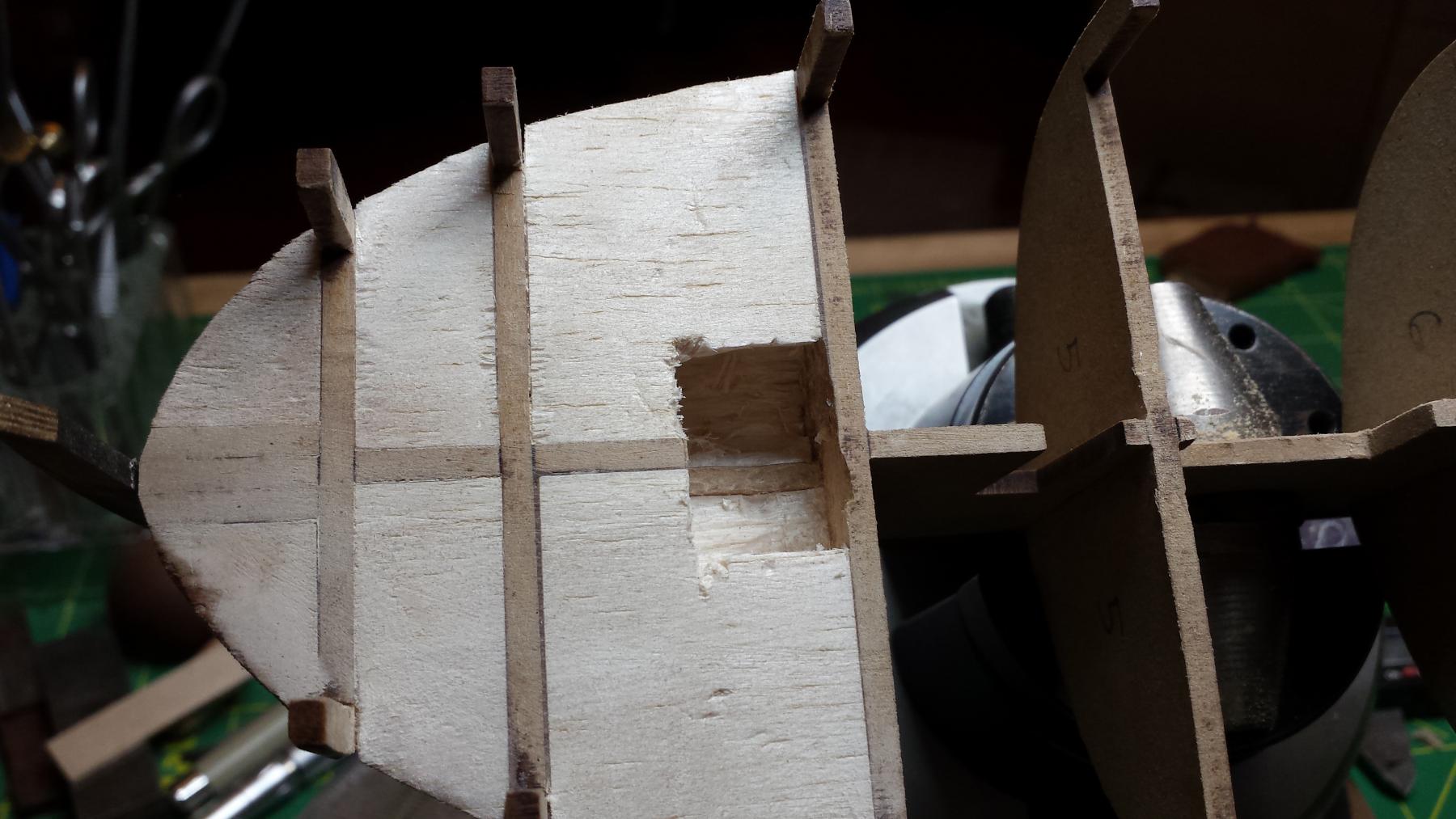
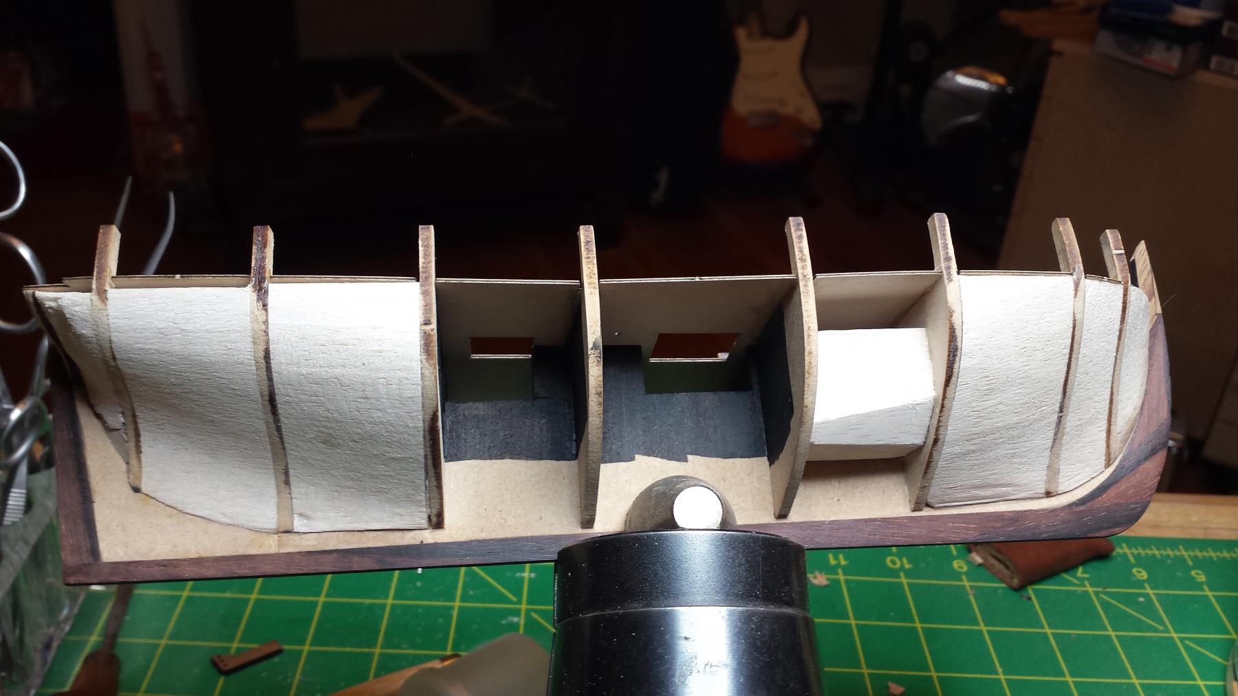
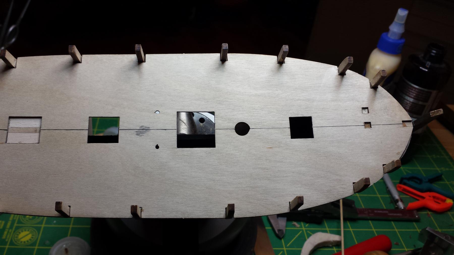
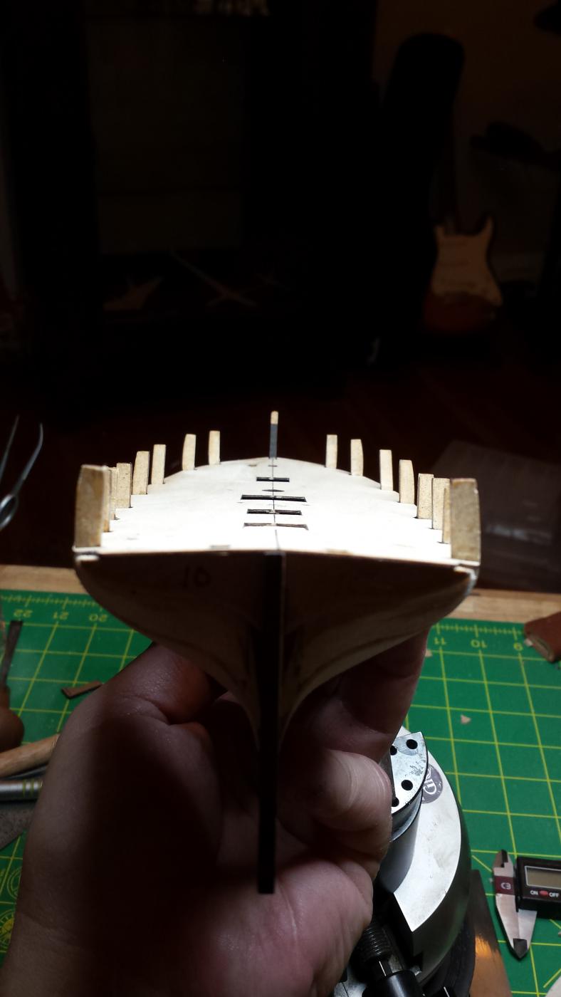
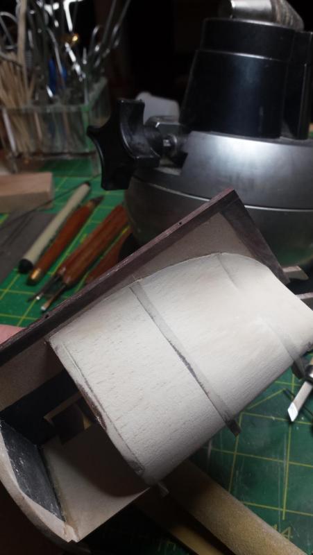
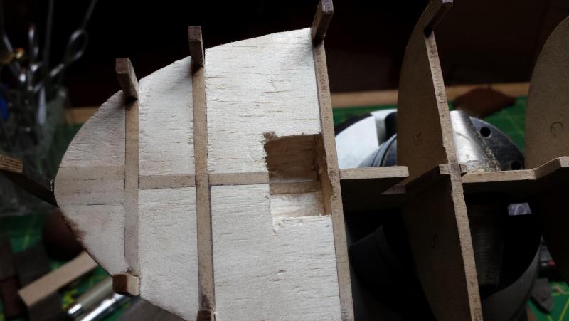
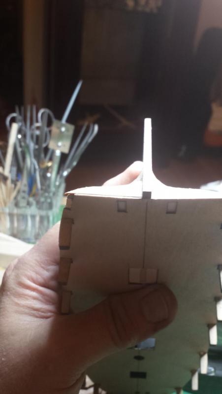
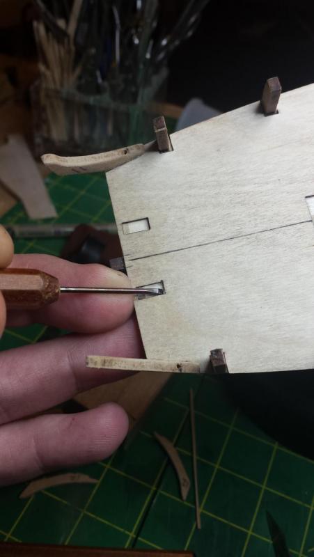
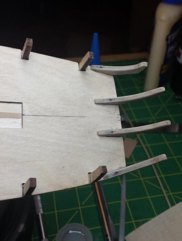
Still haven't gotten over flu but feeling better. Then I'm back at work Tuesday and first thing we have a crisis and I'm on a conference bridge trying to manage incident response with 50 or so people spread around the globe for the next 10 hours. Thanks work, I missed you too. Anyway got a bit of progress. We're getting ready to put on the deck so I wanted to make space under the gratings so, you know, there's actual space there and it should look more natural. So here we can see that involved extensive work at a level of precision that would make an Incan stone mason cry tears of joy. Either that or I hacked at it like a baboon. You can see where I cut the keel plate back under the other two grates. I cleaned up my baboon-hacking and painted matte black under the grating areas to be sure. this was actually taken during gluing on the deck, I did it by steps, gluing the bow section, then the two middle bulkheads one at a time, then the stern, all with CA. Here just the bow is glued. You can see I also added yet more balsa blocks in an uncontrollable fit of over-engineering. And speaking of which, deck looks ok and I'm happy that it has what looks like the correct inside of a toroid double curve of the cutter deck Actually is there any 18th century warship with more sheer on one short deck than these cutters? I can't think of any. The piece of wood on the bulkhead was put there to fix the deck line there so it's fair Grating cutouts look good. I sanded down the deck edges again to the "almost done" point and was ready to move on to the fashion pieces but then I noticed this little problem on the starboard counter bulkhead. Bummer how did that happen. Well, prorbably moved it out of square when I added the balsa block, but I was carefully checking them for squareness also just for this reason. Ah well. Wait maybe it's the deck..no Square. Pthhtthththtt. Have to fix it and need a special shape since I don't want to glue on a piece and then try to machine a bunch of material away, so I make a tapered basswood piece. Glued it on. This is why we taper it off-work, so very little needs to be removed now. All fixed. Fashion pieces. The MDF or whatever this stuff is is odd, it can look pretty gnarly like this but are actually acceptably smooth. Once in place though they'll get a sanding sealer coat and light sanding to remove any fuzz sticking out. You've seen me use my carbon fiber pins one way, installing them before piece goes on work, this is another way- glue hole only in piece, glue on piece, use existing hole to guide drilling of other side, install pin and sand down like an insanely strong treenail. Here I have the outer ones glued on with no pins, and am cleaning out inner holes. They're not Alexander's carving tools, they're from Woodcraft and the steel is seriously meh and I can't get a decent edge and they don't much hold what edge they get. So they're relegated to this kind of work cleaning glue out of places but they're still useful for that. You know I just realized I'm doing that with left hand. I throw and do big muscle stuff lefty but write and use tools right handed, but over time the left has learned to operate tools fairly well. And here's something else useful, you can use the pins to like pin things. The inner fashion pieces are supposed to be parallel to the rudder post, not perpendicular to the deck, so they have to sit at a cant on the deck. I sharpened the CF to a very sharp point and stabbed it into the balsa below and used it to position the piece, then flooded in some thin CA to tack it in position and then medium to fill. Added other pins to outer fashion pieces and cleaned everything up. And will continue tomorrow if the work world doesn't explode in flames again.


- 714 replies
-
- 9
-
-
- lady nelson
- victory models
- (and 1 more)
-
Fokker Dr.I by Torbogdan - FINISHED - Model Airways
vossiewulf replied to Torbogdan's topic in Non-ship/categorised builds
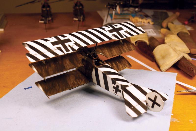
If you haven't already, go buy this book. You need it. It has like 60+ pages of 3d renderings of the aircraft from every conceivable angle showing every detail. Also if you have any questions at all visit the folks at The Aerodrome. All of the active historians are there as well as builders, people with stupendously extensive and detailed knowledge. However at this point you can answer most questions simply by searching the archives. But if you want to know what version of Bosch magneto the Dr.I had, the serial numbers of all installed in Dr.Is, exactly how it was made and the whole history of Bosch magnetos, some guy on the Aerodrome can quote the answers off the top of his head. And after you finish that one you'll be ready to take on the 4" scale version That's a good paint scheme on that one BTW, that's Paul Baumer's Dr.I and it's amusing because it has eisenkreuze- the patee crosses - all over it. He'd been badly shot up by friendlies several times and was determined to never be again. Check the other photo, you can see 3 of the extras, one each on each lower wing top and one in the center of the tailplane. With the plastic Roden 1/32nd kit I did Kirchstein's Dr.I, the one that was handed over to Ernst Udet after Kirchstein was killed, it's actually better known from when Udet flew it as there are a couple photos of it after he added his usual LO! on the cockpit side in honor of his girlfriend. Kirchstein called it his "optical illusion" and insisted it made enemies miss. Maybe that's the case since he was killed in a crash in a plane he wasn't flying. It's also cool but lemme tell you it's not fun from a masking standpoint. Your progress looks great, I hope you stay with it. Finished as you've started it will be a pretty impressive display cabinet item.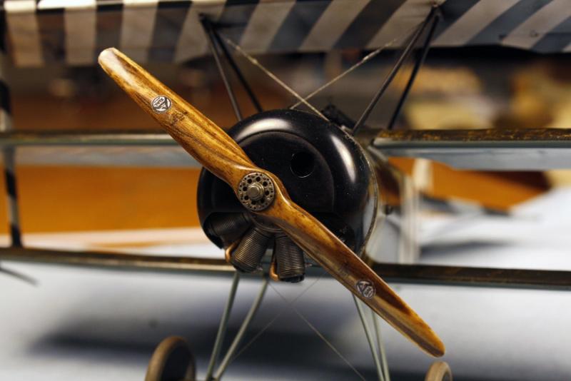
- 250 replies
-
- 10
-
-
Miniature Hand Tools
vossiewulf replied to Julie Mo's topic in Modeling tools and Workshop Equipment
-
I'm American but have spent so much time reading English authors and watching British TV that my language constructs frequently suggest British rather than American English. Considering the quality of the average American speaker, I generally consider that a compliment Work involves a fair amount of international conference calls, mostly to Singapore and India but Australia/New Zealand and Belfast, and I have to tell you that I've now heard the single worst English that is possible. It's a sound that could make Beethoven deaf. Again. George Bernard Shaw heard two words and died of a ruptured aneurysm. One of my staff gnawed off her own leg to escape the conference room: a Chinese immigrant, with a very heavy Mandarin accent, developing a VERY strong Australian accent. You know how two normal things can converge to create something so horrifying that Medusa and all of the snake heads scream in unison and run away shrieking like four year olds? Yeah well this is it. The UN really needs to step in to prevent any further immigration either way, one has to assume the Australian learning Mandarin has to be just as bad, if not worse. Back to the more important discussion of improving Admiral health..
-
Miniature Hand Tools
vossiewulf replied to Julie Mo's topic in Modeling tools and Workshop Equipment
Ok, I wouldn't call block and smoothing plane similar-sized, standard block, smooth, jack, and jointer are all distinct sizes that perform specific functions relative to each other. I mean I'm not sure I'd recommend buying the small smoothing plane but the large one I have is an altogether different animal from your block plane. But your mileage may vary and it's up to you what you get. My concern is that the jack is too big, but certainly block is much too small to flatten boards that long/wide so no I wouldn't recommend getting the handle for your block plane at all. That would make you use that plane in that mode a bit better but it doesn't change the fundamental size and you need more size. The reason I'm also against jack is that board is about the smallest that's appropriate for a jack plane, so you pay lots of money for something that applies to only one process.If you know you're going to be doing bigger work more often maybe it works out. -
Miniature Hand Tools
vossiewulf replied to Julie Mo's topic in Modeling tools and Workshop Equipment
Why are those the only two options? There are three sizes of smoothing plane between your block and the jack that make great jointer planes for model stock. Look at my build log, you see me using my bevel up smoothing plane to thickness cocobolo easily. Ah heck here is the photo. This is my highly technical setup - a piece of 1/8 scrap (I can use 1/16", did last night) as a stop, two cam clamps, and my BU smoothing plane. It works great if you can plane parallel to your surface, and I have no issues controlling size down to .001". As for which blade, you're right that the important thing is what is the final cutting edge angle of incidence to the wood (bed angle plus bevel angle for BU planes), and working with model hardwoods that should be close to the proverbial York pitch of 50 degrees. Higher for figured woods. The reason I like the new BU planes is one smaller/lower profile that makes them handier, and two I just think it makes more sense to have most of the mass and blade axis with the highest strength aligned close to the cut. These planes sharpened never chatter on anything.