


AON
-
Posts
2,791 -
Joined
-
Last visited
Content Type
Profiles
Forums
Gallery
Events
Posts posted by AON
-
-
1 hour ago, Lecrenb said:
Very nice and frame worthy Alan!
Thanks.
The neat thing is the back is glass so I can take it down and look at the other side as well.
- Lecrenb and Keith Black
-
 2
2
-
10 hours ago, Lecrenb said:
Was his sail making part of that?
YES
- yvesvidal, Keith Black and Lecrenb
-
3
-
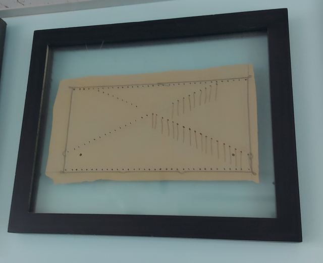
I took the Admiralty workshop offered by David years ago and it turned out wonderfully!
I have it framed and hanging in my workshop as a reminder of a weekend well spent.
- Lecrenb, druxey and Keith Black
-
3
-
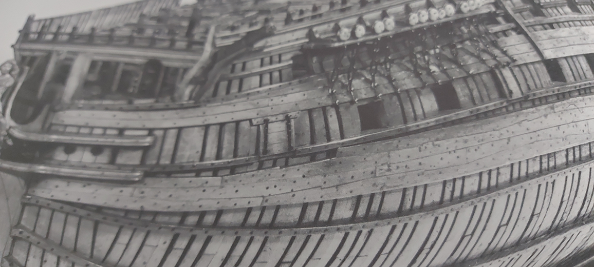
Before starting on the gun deck (again) I decided to install the wales. Per the contract the wales are hook and butt and a photo of a model of the Bellona shows this quite clearly.
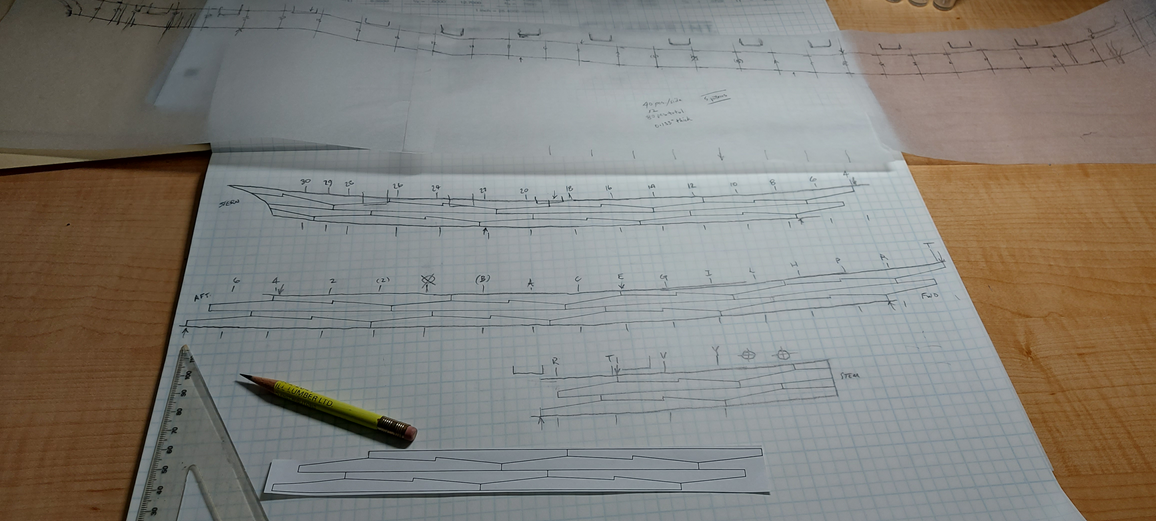
I drew some 20 foot long hook and butt planks at 1:64 scale using DraftSight to make a straight plank template.
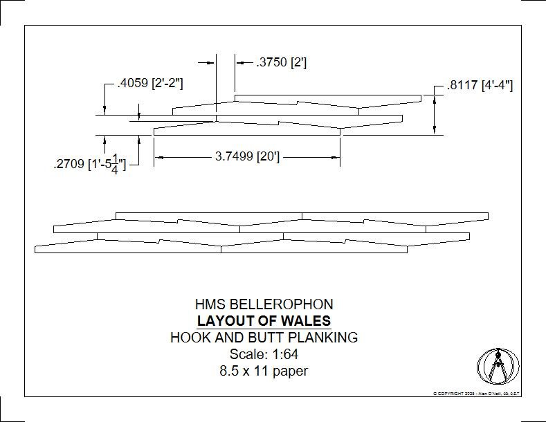
I measure off the NMM plan and converted the measurements from 1:48 to 1:64 scale. These were transferred to my timbers.
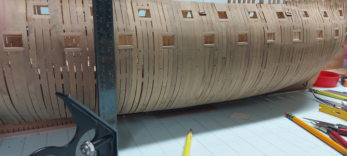
I then attached sheets of tracing paper to the model and transferred these marks to it along with some other details (gun port openings, hawse pipes holes, butt to stem post and end at the aft).
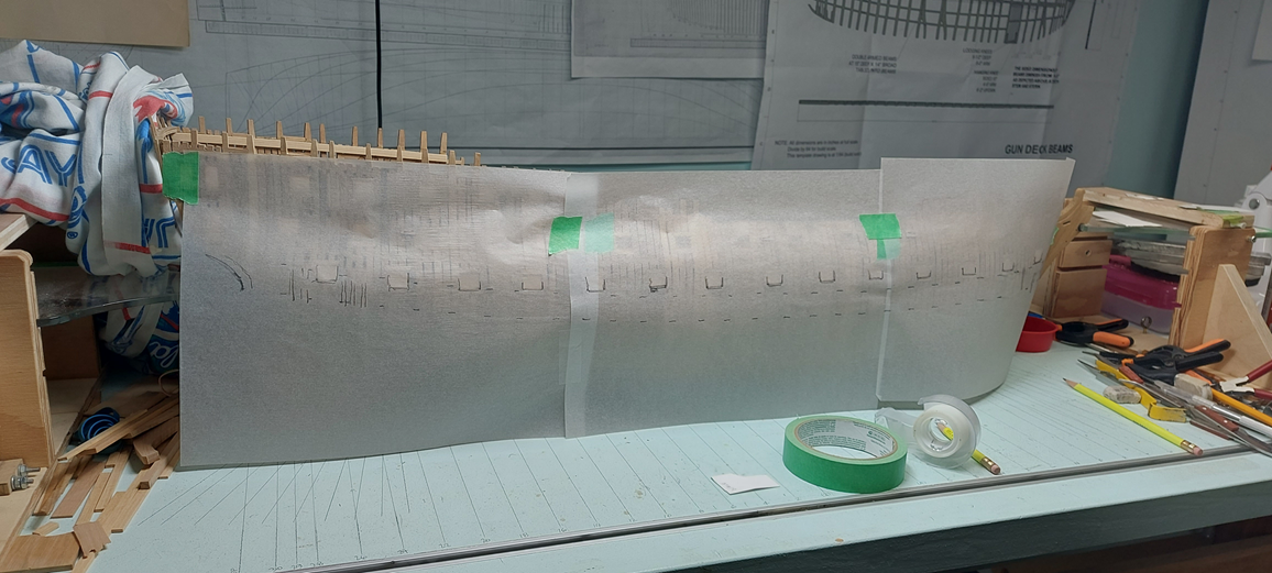
This curvature was then transposed to transparent graph paper. The printed straight plank template was cut out and slipped below and my curved templates were traced onto the graph paper.
I will be using black walnut for the wales. This stock will be cut and sanded to thickness and then two sheets rubber cemented together to allow me to cut both individual identical port and starboard planks at one time. I cannot use my black carbon paper to trace these shapes as it will be difficult to see the outline on black walnut so I’ve ordered a package of white carbon paper for the job!
Safety note: Black walnut sawdust may be toxic to some, so proper precautions must be taken when cutting and sanding. Some individuals may experience respiratory irritation if exposed to large amounts of black walnut sawdustLike everything else on this build... this will be my first attempt, so wish me well.
- Thukydides, GrandpaPhil, albert and 15 others
-
18
-
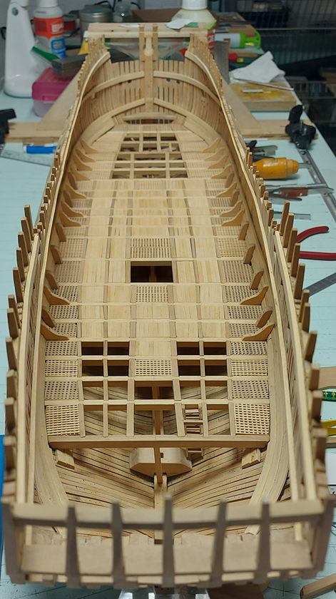
I completed my rebuild of the orlop deck… or so I thought.
The grating runs along both sides and at the bow. The lodging or (horizontal) deck beam knees are installed as are the standard (vertically upwards) knees.
I decided to add the top end of the futtock riders… faux riders. To hide the missing detail I installed the flush orlop deck planking over the area. Planking either rested in a notch cut into the beams or on a separate support ledge. I decided on the latter as it was easier then cutting more notches.
I was able to re-use the three stairs I had built, two at the bow and one at the stern.
The one detail I need to remake is the very last aft grating on both sides. I had decided to keep the support ledgers fore and aft and the battens port/starboard… but for some unknown reason I skewed the last aft set. These will be torn out and made over.
-
I found the second or lower of your images on Pinterest posted by Niko Henrichs.
No details or attributes for the scanned image.
Without that information I would hesitate to make a decision.
I await input from someone with the knowledge.
-
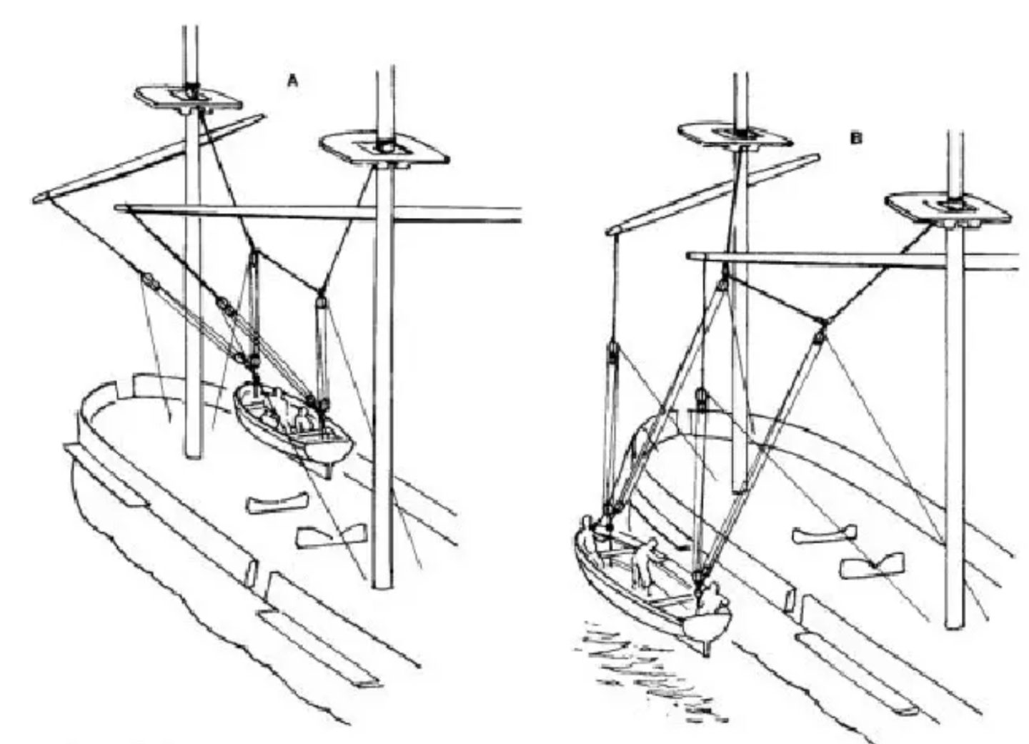
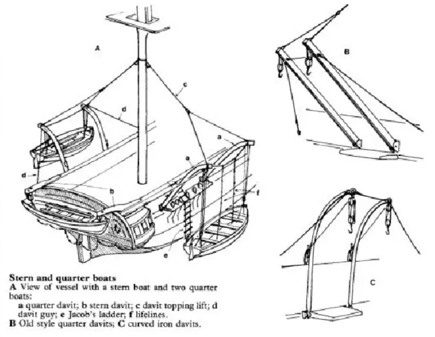
I found the first one in Seamanship in the Age of Sail pg 283
below are images from pgs 284 and 285
-
Could you provide the sources for each figure please.
I've only seen the one on top, not the one below.
I haven't any expert knowledge with this subject and so, am interested in the responses
-
As important, could someone explain how the anchor could be raised (man handled) in such a short distance between the hawse pipes and the forward grating when the capstan is way back aft?
Seriously, I'd like to know.
I don't understand.
-
Looking at the location of the capstan in image 1588a I tend to agree with you as to where the anchor cable ran utilizing a vyol (viol) and nippers.
The cable would be coiled below in a heaping stack, one to the port side and one to starboard (or larboard) and it involved a major portion of the crew over a good portion of the day to accomplish the feat.
- glbarlow and Blue Ensign
-
2
-
I simplified my description some... left out steps.
I mark them insitu, remove them, score the pencil marks on the fore/aft face, chisel with the grain from port to starboard then pass the file to ensure flatness.
My carlings and ledges are cut square to length then with my bench sander support tilted at an appropriate angle, I sand the ends to fit the notches.
I had tried cutting them on the model as I believe David Antcherl and a number of others do and it was a disaster.
I tried cutting them off the model, on the bench, and they split on me a number of times, so I gave up!
How I do it has extra steps but it works for me.
You do you!
-
-
You need a helper you can blame it on! 😏
- Andrewiscookin and Nirvana
-
 2
2
-
I don't understand why it applied so unevenly.
-
Heard back and emailed you his contact info.
- Lecrenb and Keith Black
-
2
-
I've just sent him a note.
- Keith Black and Lecrenb
-
2
-
Bruce,
There is a fellow in our MSON club that 3D models and resin prints figures.
He made one of me playing my fiddle sitting crosslegged for placement on my orlop deck (deep in the ship for anyone that tries to see tha far). I can ask him if he has anything suitable and have him contact you if you wish.
Alan
- Keith Black, druxey and FriedClams
-
3
-
I think salt water ocean shallow and fresh water lake shallow might be two different things.
Also, isnt gravity involved when cannon shots fly.... they drop. Not all shots were balls. Sometimes they might even be two balls if close enough. Chains and grenade style balls were also used.
But more importantly, shots to the rigging and mast do damage to the gun deck (weather deck of the Niagara) when it all collapses.
There would be quite the mess for the cleanup crew. 😉
-
Going to the source... what a novel idea.
😉
- Keith Black, druxey, FriedClams and 1 other
-
4
-
Bruce
Ray (MSON) had built the GJØA.
You can email and ask him.
I would have thought it was gear driven... but that is from someone that has absolutely no idea! 😉
Alan
- Keith Black and FriedClams
-
2
-
Good morning Bruce
I am going to send you 3 PNG photos from A Ship Modelmaker's Manual by John Bowen that might have the answer.
The images are too large to post.
Cable Stoppers pg 41 fig 64, pg 141, fig 252 and pg 166 fig 311.
Alan
-
-
Thanks for the video... I learned something from it about loading bullets!
My only thoughts were for the use of the train tackle. Yes the gun would recoil on firing so the train tackle was mostly used to retract manually. I cannot envision that one getting used and wonder if I might experience the same thing on my ship, and if so what might be the resolution to the issue. I will reflect on it for a bit more... quietly in the corner! 🤔
- KentM and Ryland Craze
-
2
-
Kevin.
While watching your video and seeing the train tackle that could not be used as it was already hauled in as much as possible... I wonder if they would have used the port deck eye with the starboard gun and the starboard deck eye with the port gun? This would allow them to pull the gun back all the way to the eye and possibly expose the muzzle inboard for loading.
I know it will be covered and hidden from view... but I am left wondering if this was the solution?
Alan


HMS Bellerophon 1786 by AON – scale 1:64 – 74-gun 3rd Rate Man of War - Arrogant-Class
in - Build logs for subjects built 1751 - 1800
Posted
Almost back to where I was before I tore out the orlop and gun beck.
Gun deck beams cut, edges softened (sanded), tacked in place, marked for carlings.
Centre alignment double checked with some square stock set in the three mast steps. This was eye balled from the transom to the bow. Looks acceptable.
I also double checked the deck height with a 32 Pdr and my 4" thick deck planks will need to be slightly thicker... which is better than thinner I suppose.
The height between decks looks good with 3D figures. I plan to have at least this fiddler (me) on the orlop with his seaman's chest.
I also have my wales traced onto the black walnut ready to be cut out. I numbered the pieces so hopefully I don't get mixed up.