AON
-
Posts
2,871 -
Joined
-
Last visited
Content Type
Profiles
Forums
Gallery
Events
Everything posted by AON
-

THE 74-GUN SHIP by Jeronimo
AON replied to Jeronimo's topic in - Build logs for subjects built 1751 - 1800
verrrrrry nice indeed! so nice I had to go back twice -
what is the ideal modelling table?
AON replied to AON's topic in Modeling tools and Workshop Equipment
now that is thinking outside the box! -
Having worn navy blue as a sea cadet in the late 60's and early 70's I can attest to there being a slightly noticeable difference between it and black Unfortunately I wore green after that. (The bell bottoms made a great life preserver by the way) For the technical fellows out there.... CMYK value of True Blue Cyan = 84 Magenta = 53 Yellow = 0 Black = 0 CMYK value for Navy Blue Cyan = 100 Magenta = 98 Yellow = 14 Black = 17 CMYK value for Black Cyan = 75 Magenta = 68 Yellow = 67 Black = 90 Of course this has nothing to do with early uniforms and colours which was the original question and so I apologize for that.
-
took me a moment to look away and spot the others hanging off the shelves!
- 969 replies
-
- 3
-

-
- hahn
- oliver cromwell
- (and 1 more)
-
holy sh......ishkabob now I see it if I hadn't seen what you can do I'd say you were crazy this is going to be a treat to watch
- 59 replies
-
- 5
-
-
- norske lowe
- billing boats
- (and 1 more)
-
This is the response I rec'd this morning from our local SW rep. I was able to confirm that this program is in effect.... (snipped) ... you can purchase the license online. Support is provided as well.... (snipped) any files created with this edition are watermarked. The link is https://store.solidworks.com/veteran/default.php price is $20 (I am assuming it is US$) at this site it states SW 2015/16 does not work with Windows XP (this may be a problem for me) Looking at the application form (DND 2381) for the NDI 75 card you must have 10 or more years service in any component of the Canadian Armed Forces to qualify. You require 2 colour passport type photos and payment of a $15 processing fee.
-
Terry I need to check in here more often I just sent a note to our SW provider to ask if this is true because last time I spoke to him he said there were absolutely no special deals for anyone. If this is true I can hopefully get a card for $15 (or maybe send them a copy of some paperwork) Alan
-
Of all the challenges this ship will toss your way I just can't seem to see past the dust! I'd say good luck but you're in a group that doesn't need it! So happy refit! Alan
- 59 replies
-
- 4
-
-
- norske lowe
- billing boats
- (and 1 more)
-
You made me laugh not once but twice! We all would steal AEW's whole library and I love the shot (pun intended) with the level!! I appreciate the large photos (and not just because I'm old). I just discovered a few weeks ago that if I use the roller on my mouse with the CTRL button held down I can zoom in on the photos so the large photos plus the zoom works really well for me Keep up the fantastic build as this guy literally half way round the world will be learning from you.
-
My New Found Respect for Table Saws
AON replied to AON's topic in Modeling tools and Workshop Equipment
I've spent the week watching table saw videos on line and it is amazing what some people creating these instructional videos do. Of course I'd not have given it a second thought before last Sunday. I've decided I do not like the back corner edge push stick as much as I thought and those pads still put your hand too close for my taste. I'll be creating a hybrid push pad/stick to assure my hand is well back and I'll be making myself a RIPPING JIG ( ). The scariest TABLE SAW video describing kick back was found here ( ) This guy has prooven the push pad with a low over the top grip is a bad thing. Once again I did not experience kick back, my accident was due to the weakness in the wood due to the hole allowing it to bind and twist from the outside. My table saw guards, riving knife and toothed anti kick back attachment did absolutely nothing for me. -
My New Found Respect for Table Saws
AON replied to AON's topic in Modeling tools and Workshop Equipment
I've been telling people it is a knitting injury you should see the looks I get -
My New Found Respect for Table Saws
AON replied to AON's topic in Modeling tools and Workshop Equipment
thank you druxey I thought I was smart enough to avoid this type of incident smart has nothing to do with it RESPECT for your tools means more then taking care of them -
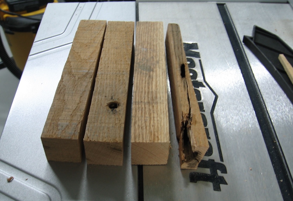
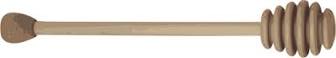
How to Make a Honey Stick... or... My New Found Respect for Table Saws Every morning at work I enjoy a good hot cup of tea with honey. I had been thinking about it for weeks and one week ago on Sunday, August 2nd, I decided to make myself a honey stick. I decided to use oak as I have some old oak skid pallet parts in my stock pile and I just love oak. I took a board (about 1-1/2" thick) and cut a short length (8-1/2") off of her. I set the fence on my table saw to the thickness of the board so I'd end up with a square piece to put on the lathe to turn it down and shape it. The cut went smooth without incident.... I should have stopped there. In my experience the first piece never looks quite good enough and I knew I could get another cut out of the drop so I decided to prepare a backup piece. Well the board had a bolt hole in it so I'd have to cut that out, and the outside edge had what I call a worm hole (more likely a wood wasp burrow) and that would not be good. On close inspection I calculated I could cut it down without resetting the fence. The second cut went without a hitch, bolt hole gone. The final cut was going wonderfully until the very last inch and "what the [bleep] just happened!" I grabbed some paper towel, clamped it to my index finger with a death grip and was rushed to the hospital. At the hospital the nurse told me I could let go now... well I couldn't. My hand was cramped in place. I could not remove my left hand from my right. It took all my concentration and then it opened just enough to slide my finger out. I had to press it against my thigh to get it to open the rest of the way. WHAT A MESS. I couldn't bring myself to turn and look at it. I was sure it was cut straight up and I now had a forked finger tip. The nurse wrapped it back up and told us it was going to be at least a five hour wait. As we are blessed with an Emergency Unit in our home town I'd have been better off if I was having a heart attack (heaven forbid) as I would then had been getting immediate care. We left and drove the 15 minutes to the next town that is designated Urgent Care and I was tended to completely within two hours, including x-rays. I had removed 3/4's of my finger nail and the meat just below it and, thanks to guardian angels, just missed the bone. I am healing quickly. I can lower my hand without my finger tip throbbing, and every other day the nurse changes the bandage and that process hurts less than the last time. So what happened? The wood does not show the classic signs of kick back in that the part between the blade and the fence did not climb up and over. The small piece with the worm hole is twisted and cracked. It was outside of the blade, I was using a push stick inside of the blade. I always used my hand outside and removed it as it approached the blade. I was just about to pull my hand away as the piece twisted and my hand was drawn underneath and inwards just in front of the blade and ... bad luck would have it was swiped. I will never, ever, ever put my hands anywhere near a power blade, ever again. EVER. (I make tonnes of scrap wood and will use it) I'd post photos but if I don't want to look at it why would I let you. I learned to type using all my fingers way back in high school but have since resorted to two fingers. Strangely I use the index finger of my left hand and the third finger (next to the index finger) of my right. So my typing ability has not been affected. How strange is that. Also, in 1990 I had the nerves along one side of my neck cut during surgery while they removed a tumour that had wrapped around them and from that I'd lost the feeling in finger tips of my right hand. I was just mentioning to my wife the day before the accident that I'd noticed the feeling had come back. Oh Joy, just in time! As for the honey stick, it will get done but not for awhile. I've got more healing to do first.

-
Sorry to say but you are assuming the floor in the room is level, the table top is level and the vertical blinds actually hang vertically. I do not believe any of those are true for my home. On the other hand if I ignore the blinds and compare it to the deck amidships it looks to be perfect!
-
women go figure
-
wasn't that Ricky's line to Lucy?
-
I started using Inventor after the crash and burn of 2015 (that is how I am referring to it) Many moons ago at another company, when we were looking int switching to a 3D program we compared SW to Inventor and the result of that "test" was that a task was completed with SW by executing fewer steps than Inventor and that was perceived as time = $$$. Then I worked at another firm for a year and a half and they use Inventor so I found out a few more things about the program. I would have to agree with a present working associate that Inventor is the "workhorse", but somehow I still prefer SW for easy of use. (and, not that you asked, but splines will be the death of me)
-
quarterdeck or forecastle?
-
FYI - I had a quote for work months ago and the basic SW version is $3995US
-
Thank you Don presently having some issues appreciating how Inventor works with splines and mirroring seems they may need to be constrained every which way !!! as when mirroring things go wonky. Presently I am very frustrated with this program... it is the learning curve
-
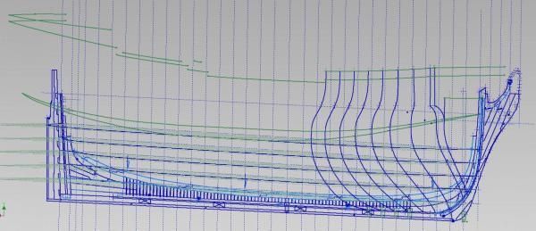
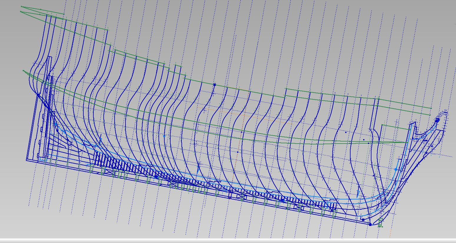
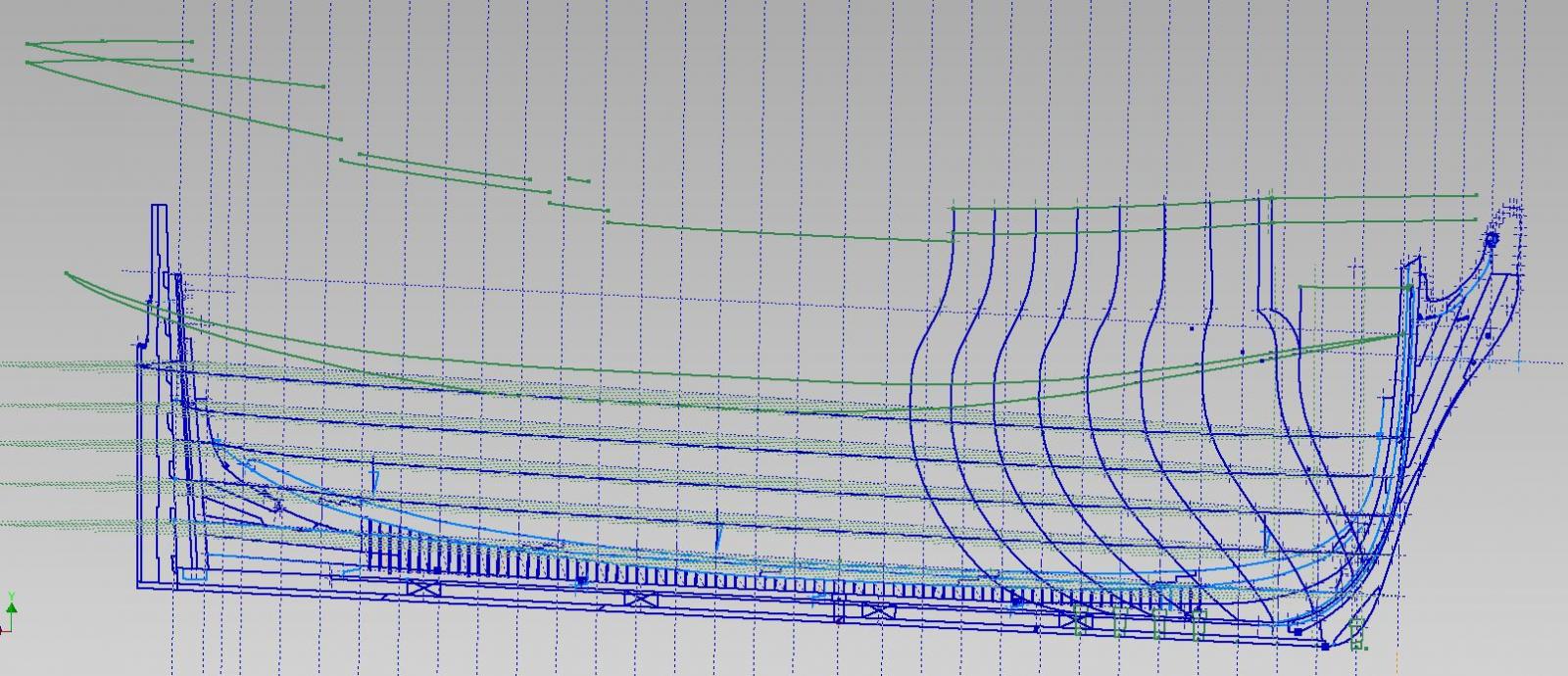
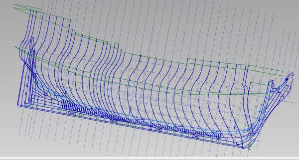
Well I completed the hull shaping at each station line. Have to complete the stern transom shaping. I think I will draw the frames, and this time extrude between them (rather than lofting), then slice and dice into individual frames to make my templates... which was were I was before the crash. Almost there. and btw July the first.... Happy Canada Day, eh!
-
shaping the hull at the station lines going much quicker than the first time and the line work is much cleaner It pays to work smarter... but learning to work smarter means you have to learn in the first place So my computer crash was an opportunity after all.