HOLIDAY DONATION DRIVE - SUPPORT MSW - DO YOUR PART TO KEEP THIS GREAT FORUM GOING! (89 donations so far out of 49,000 members - C'mon guys!)
×


AON
-
Posts
2,868 -
Joined
-
Last visited
Content Type
Profiles
Forums
Gallery
Events
Everything posted by AON
-
 Good evening Mark. I read your comment earlier today and of course it made a huge impression on me. But now after some hours it seems like a challenge .... if only I had the talent! On another more achievable note... After considerable calling around I found a local source of 22 gauge solid copper wire (if I should chose to use it). The only source is indoor telephone cable I bought 12 feet at 20 cents a foot (= $2.40) It is four strand so I have 48 feet in total. A co-worker caught me checking the diameter with my vernier and asked what it was for. After I told him he remarked that I should have talked to him as he has coils of it at home! Isn't that the way it goes.... I could have bought a double-double with that money. (I wonder how many are going to have to Google double-double?)
 -
Both had caught my eye some time ago Mark!
-
"Rowing Dinghy" - a kit build to learn basic skills (moved by admin)
AON replied to jsolka's topic in Wood ship model kits
On a more serious note... I have an old marble pastry rolling flat to use to keep items flat for assembly but hadn't thought to use it (or glass) for sanding I have seen here on the forums (and so have used) nail file boards for sanding. That was handy and timely. It is tough learning when to say "when" (to know when to stop sanding). I've read where some use old fashion carbon paper slipped between pieces during dry fitting to mark / highlight the bumps to sand. I have also found it is easier to stop early and dry fit pieces to check many times than it is to stop late and have a bad fit ... I have a good scrap collection started to prove it. -
"Rowing Dinghy" - a kit build to learn basic skills (moved by admin)
AON replied to jsolka's topic in Wood ship model kits
good start ... but now I am hungry! -
Is it wrong to admit that I take great comfort in seeing the mistakes of more experienced modellers? (because I do) It somehow makes them quite a bit more human... and so I move forward. My son did indeed find thicker hemlock lath and brought it over last night so supplies are plentiful.
-
Gluing represents permanency that I will be looking at throughout the period of the build (5 - 8 years ???) I hope to get it right but I'd hate to realize 3 years later I got it wrong. That is the scary part... learning to live with it looking back at me.
-
Thank you Druxey. The long 's' and I are very good friendf prefently.. When I sat down to start I made a decision on exactly how I would approach it and I was committed to correct each long 's' and so I have. Then there was 'rabbit' and 'fastned' and.... the list goes on. I am very happy I have done this otherwise the darn contract would still be a myftery. I found reading it was like reading The Last of the Mohicians... the longer I stuck with it the easier the language prose became. I will admit to being a bit hesitant to start gluing and pining parts.... but I can see myself starting very soon... visualizing. My son claims he found some thicker lath in his pile late yesterday so I will be remaking the parts I must in the knee of the head and stem pieces as I start gluing and pining them. Thank you all for following... it's going to get scary really soon. Alan
-
Today I cut and dry fitted the last two pieces of the stern deadwood and keelson (template items marked 9 and 10) I also cut two strips 8" thick (1/8" to scale) x 22" wide (0.3438" to scale) for the rising wood that sits on top of the keel. Actually my pieces are ever so slightly larger (approximately 0.01" in both thickness and width). They would need to be cut to short lengths with scarph joints. I will not do that until I am ready to glue and pin it together on the keel assembly. Today, I also remade my boxing joint piece. This would be the third time. I had trimmed too much on the upper scarph joint. I have also been busy doing something very constructive over the last two weeks. Never having been able to sit down and read nor understand the complete build contract I decided to transcribe it (type it out)... only the first 21 pages as the last few pages are payment schedule details that will not affect my build. I've added some spelling corrections for today in brackets next to the questionable words; below each paragraph I've added explanations and descriptions for unknown words or phrases and I've added reference books, pages, image information so when I am at the point in the near/far future I can find it again quickly. Presently I am transcribing page 20 of 21... this would be typed page 57 for me. I've attached a PDF of the first 3 typed pages to give a better sense of what I mean. Making Sense of the Contract.pdf
-
Joshua I typed in - Free Google E-Book and the following website popped up https://www.google.com/cse/home?cx=000661023013169144559:a1-kkiboeco I typed in a book name I wanted (example: Anatomy of the ship Bellona) and there it was about third from the top listed as free and downloadable Some books are not PDF but there are You Tube videos explaining how to convert the file to PDF Some books are not free but they offer viewing of pages... when I stumble on some pages that are useful I take take a screen snapshot and save it for reference. If the whole book seems really good and no free e-book version is available I will try inter-library loan (books are loaned to individuals from libraries across the nation (not sure if you have this available with you library system). It may take a few weeks but then I can view the whole book and decide if I it is indeed that good and I should purchase a copy. Presently the best real purchased books in my library are the 4 volume set of The Fully Framed Model. My copies are quite new but to look at them today you might think I've had them awhile. Alan
-
Joshua I am not quite as smart as I might seem with my response. I am just beginning my first scratch build (in a very long time) and learnt the term myself not to long ago! There are quite a few free Google e-books available (I've snagged a few) that have turned out to be real gems (for me). Alan
-
typical cant frames
-
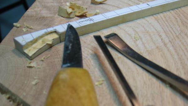
People focus in on the strangest things, eh. For me it is you neat brass STEEL right angle gauges! Coming along very nicely (PS: looked like brass to me . Must be the lighting)
-
Good luck! let us know how your test run goes. Alan
-
Good morning Josua I use Draftsight every day and the free version is quite good but not perfect. I've been draughting in pencil since 1970 then switched to AutoCAD R12 in the early 90's, then Solidworks 3D and Inventor 3D. Had to take courses for all of them to be productive. Now as I said using Draftsight for straight 2D stuff. There are many other free programs out there and you will hear the same about them. I am sure some are better than others. I'd suggest you upload them and try them out. I imagine that if you have any level of experience in CAD draughting (drafting) you will be able to tell which you prefer fairly quick. If this is your first attempt at drawing in 2D with a CAD program, it is easier then it might appear at first, you will need a good tutorial to learn the commands. Apparently draftsight offers them, I've never looked at them. Alan
-
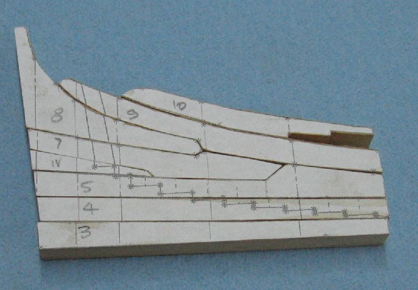
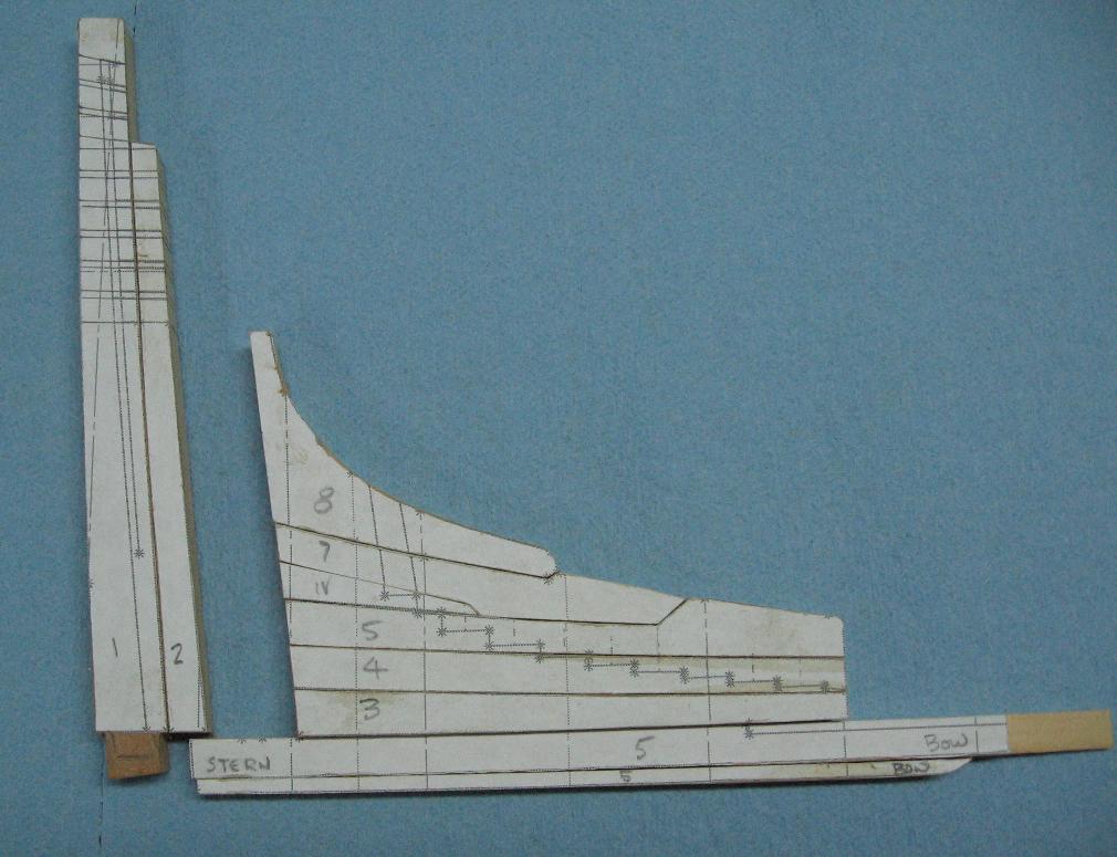
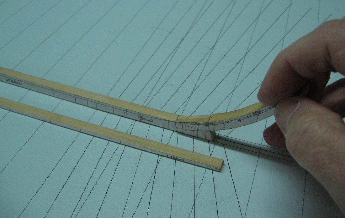
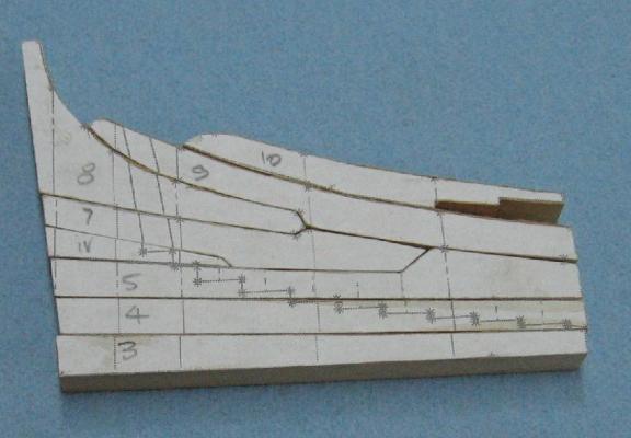
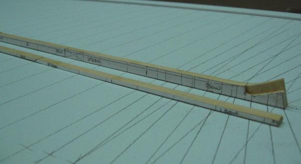
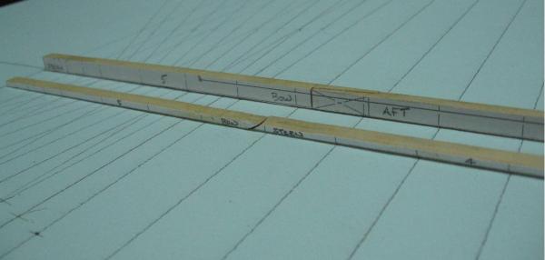
Below is the photo of last weekends Stern Post (1) and False Stern Post (2) along with the earlier Keel and False Keel Today I made the Deadwood pieces and the Deadwood Knee (8) with one piece left to fit above it. Hope to have it done tomorrow. You will note the one piece marked with the roman numeral (IV)... that's because I made this piece three times before it fit proper. That little wedge piece was a tough one to fit. I've to remake the Keelson pieces... yet to make the Rising Wood.... and taking a good long look at the Stem assembly pieces which were the very first parts made. I think I may take another shot at them as I've been doing a slightly better job lately. Milled down more hemlock lath but cannot seem to find another ceiling piece in the pile. Those are thicker (1/2") and will mill down to the necessary 26 inches (0.4063" to scale). Presently I am getting 24.8 inches (0.3875" thick). The ceiling pieces must be at the bottom of the pile, under the tarp, covered with snow in my son's yard. Somehow I don't think 1-1/8" inches (0.0188" = 0.46 mm) will make much difference in the end, but it would be nice to be a wee bit closer. Possibly I can keep the inboard pieces. I'll have to sleep on it. Oh yeah... the monofilament line came it and it looks good! Have to keep reminding myself to slow down as I am itching to glue something together.

-
Found the following which may be of some value (2 selected pages in attached PDF) Officer's Wardroom accomodations Bellona - Conway - Anatomy of the Ship - The 74-gun Ship.pdf
-
You`re young yet wait when you get older and you`ll appreciate the magnification so much more!!!
- 968 replies
-
- 3
-

-
- hahn
- oliver cromwell
- (and 1 more)
-
I just cut and sanded the stern post and false (inner) stern post. Left some material at the bottom of the stern post for the tenon into the keel. The fit of these two pieces are perfect! (photos to be posted later) I have not tapered them as yet. I will wait until I have the stern post pieces together and then taper them as one. The stern post assembly is 1'-11" square at the head down to the deck transom, and then tapers to 12-1/2" on the keel The keel is 12-1/2" athwartships at the stern tapering from some "x" distance from the original 16" athwartships at midships. As this is a mere 1-3/4 inches of tapering of the keel per side, which equals 0.027 inches at 1:64 scale I am not too worried about where to start any taper as no one will likely notice it.
-
Short report of progress. Cut out the stern post, false stern post. deadwood at the stern and keelson pieces. By the time I was done a good portion is IMO no better than scrap. I should feel bad about it but I don't.... because I feel I can do a whole lot better. I learned a great lesson by it and am reminded of something I read here on another log: 'that you should treat each piece like a model'... so I will try a new approach. This morning I re-cut ALL the paper templates If time allows, as a good portion of Sunday is family day, I will mill a new piece of lath to the max width of the stern post. Then I will cut and finish one piece at a time. Concentrating on the one piece as there is no feeling of being rushed to get more than that one piece done.
-
Bob I would have responded earlier but I just saw your post. Up here in Canada you have to be a registered student to get a free copy When I was laid off a few years back for 18 months I had an in with the local representative and after explaining my situation and that I was trying to teach myself they mailed me a free copy. Alan
-
Ordered 30 lb black monofilament from E-bay as suggested by a follower earlier. (thank you!!) Even after adding in shipping and $US exchange it was cheaper than the big box stores up here! The smaller stores I frequent do not carry black. I decided on 30 versus 40 lb because it was listed on the website as being 0.023" diameter which scales exactly 1-1/2" diameter at 1:64 According to charts 30 lb should be 0.018 to 0.022" and 40 lb is 0.022 to 0.026" Having checked the contract I have from 7/8" and 1-3/4" bolts so I think the 30 lb will look reasonable for any of these sizes. Also picked up black tissue paper at Michael's at lunch today to simulate the tar covered flannel or horse hair where used. Getting closer to assembly!
-
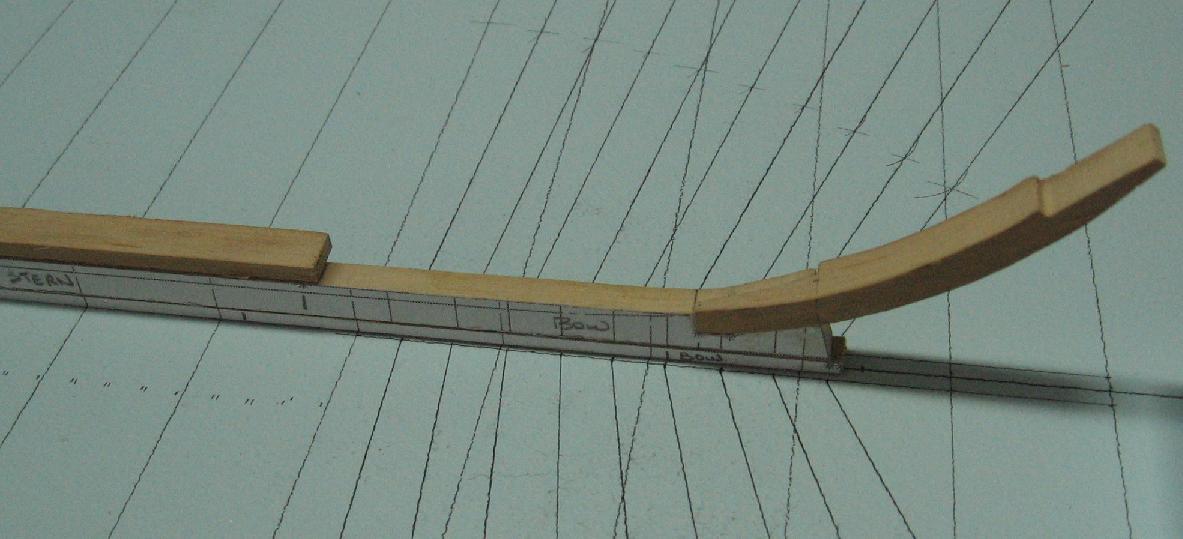
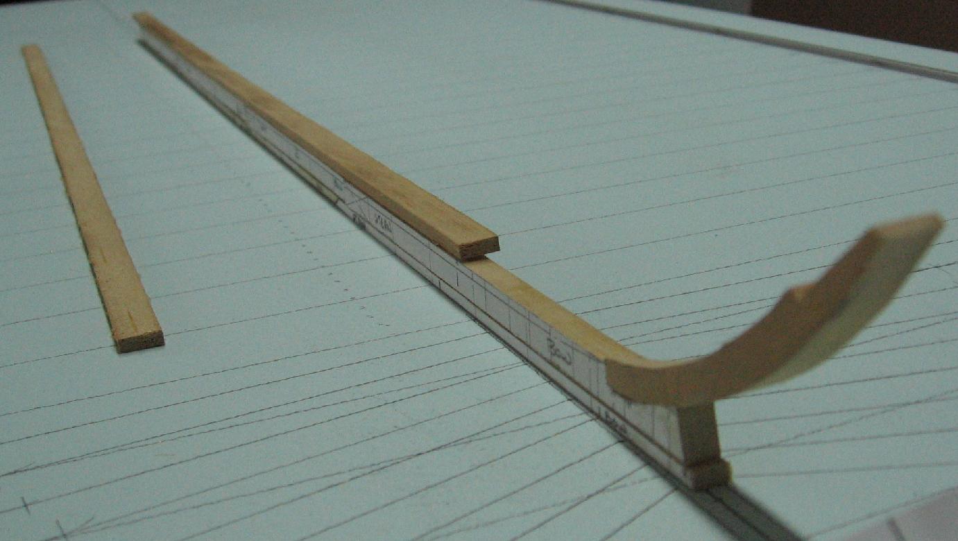
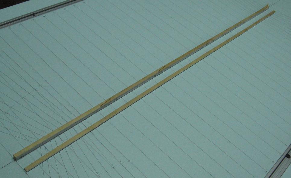
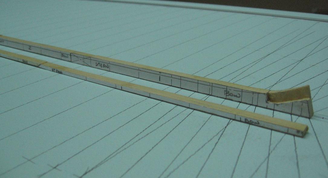
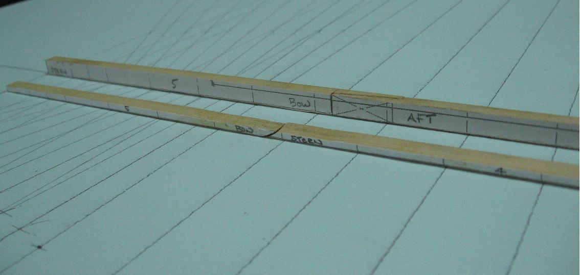
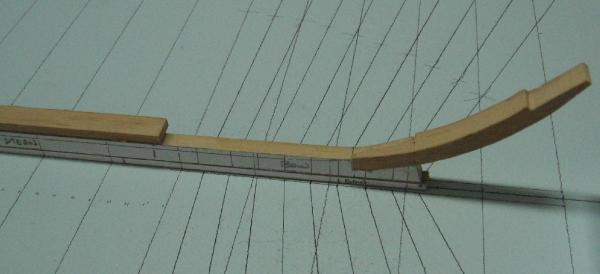
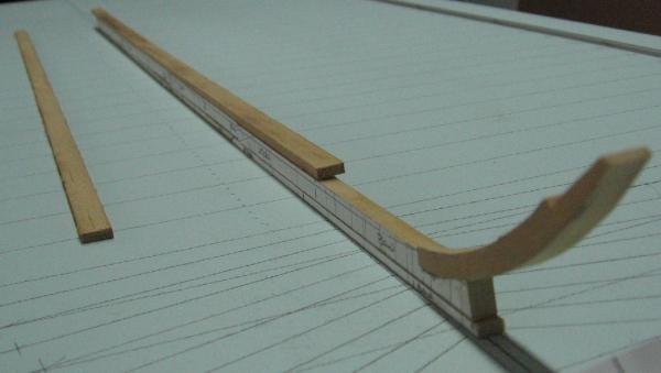
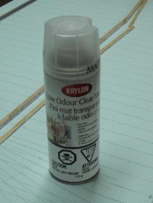
Completed the remake of the stern keel piece and the lower stem post piece.... and I got the joint correct this time. I also sealed (three spray coats) the top of my table so I will not smudge the pencil layout marks I made. Below are a few pics. Everything still dry fitted. I will work on the stern post and aft deadwood pieces next weekend.
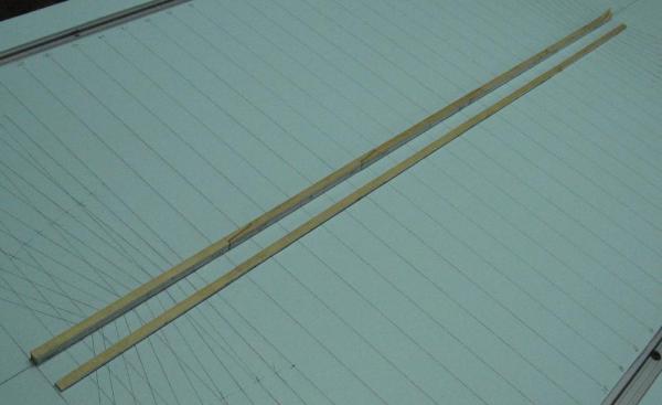

-
OH YES And feeling quite dumb about the whole thing as I held the pieces "side by each" to assure it wouldn't happen. I am somehow certain I have not yet proven just how dumb I can be ... bigger and better misteaks yet to happen I am sure.
-
Hello Mark, Thank you for visiting and for the suggestions. I have the set of the three draughts of HMS Elephant and one of Goliath. I also have copies of the build contracts for HMS Bellerophon and Elephant. Being an old time draughtsman in this new age computer drafting world I've chosen to draw a 3D image to create a model of the hull and then 2D templates to start my build. I finally get to use my old instruments again, but down in my workshop. I hope you will visit again and include a link to your build as I should like to see how you come along! Alan
-
Two weeks have passed and not a lot to show. I managed 3D modelling and 2D drawing up quite a few frames only to realize I had a compounding error in them as the lower scarph joints rise in elevation on the real Elephant's plans but not in my version. Made corrections over last weekend and then caught some bug Monday that had me down for the rest of the week. Head ache, muscle aches, chills, unbelievable fatigue but none of the more nasty possibilities. I cannot recall the last time I was sick on work days. I normally get sick on Friday at about 6 PM and am miraculously cured by Monday in the wee hours of the morning. Feeling considerably better today so I went downstairs and cut the keel and false keel pieces and then the scarph joints in the keel pieces. Immediately buggered the first attempt ... and after all those practice runs a few weeks ago! Then I began cutting the boxing joint in the forward most keel piece and was quite happy with the result. Began to cut the mating joint in the lowest stem post section... checked, double checked, triple checked, marked the waste half with with an "X"... and yes I then cut it wrong. So now I have two pieces that without question need a "do over". Templates cut and glued to some drops from earlier cuts.