AON
-
Posts
2,869 -
Joined
-
Last visited
Content Type
Profiles
Forums
Gallery
Events
Everything posted by AON
-

Mary Rose 1545 by tarbrush - Scale 1:72
AON replied to tarbrush's topic in - Build logs for subjects built 1501 - 1750
OMG just goes to show you never know what tomorrow will bring Praying all your tomorrows are exponentially better -
De Zeven Provinciën 1665 by Dražen - Scale 1:45
AON replied to Drazen's topic in - Build logs for subjects built 1501 - 1750
wow!- 487 replies
-
- 1
-

-
- ship of the line
- 80 guns
- (and 1 more)
-
Every time I start a piece I say a small pray for guidance from above: Please Lord tell me "when"
-
Thank you very much for the note about the error in TFFM (even the masters are due their one misteak) Printed out your correction description and inserted it between the pages of my volume copy for future reference!
-
seems like possibly Cherry (?) hard to tell
-
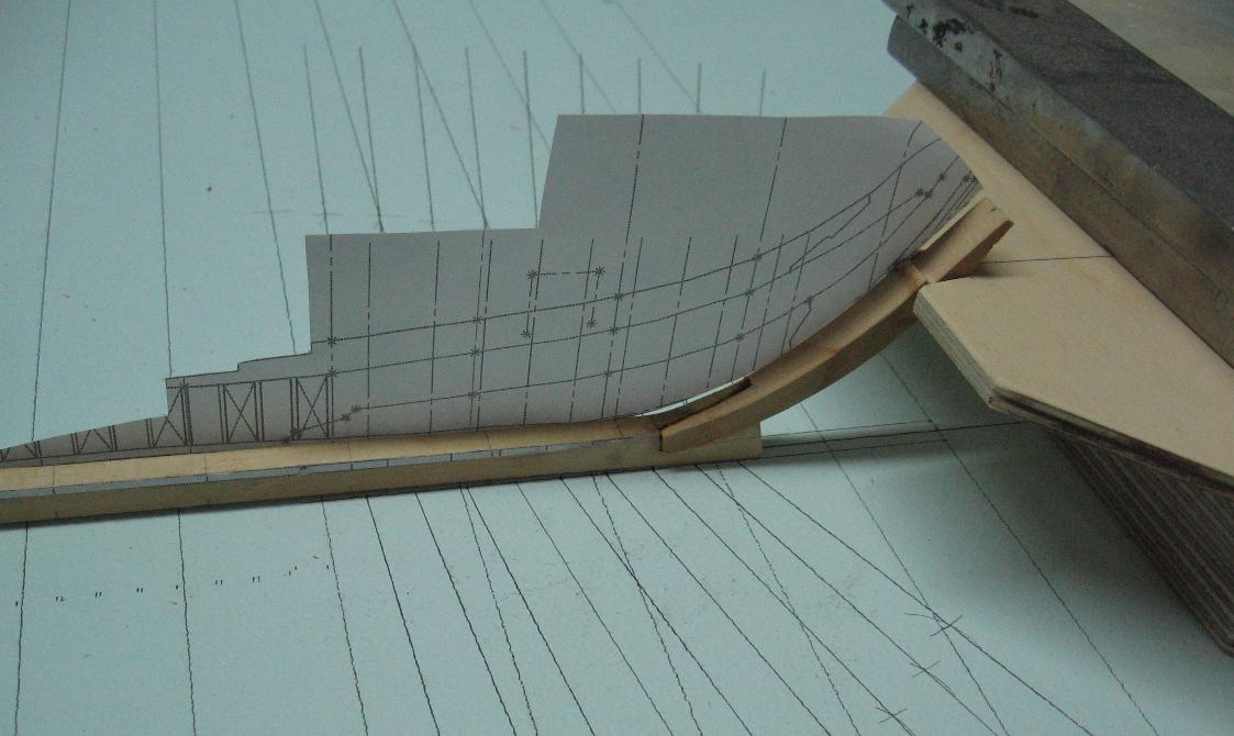
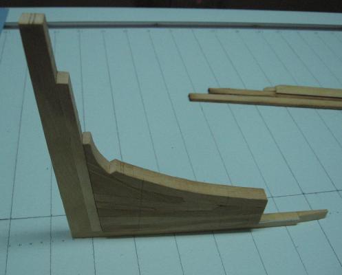
Sunday 27 April 2015 Completed the bow support frame and plate assembly. Presently the lowest position is too high but it is standing ready for the next piece Also chewed on Druxey's recommendation. Have decided to increase my work... I will do it both ways, one plane as started which I can turn off and one plane with timbers shifted. The latter will be more work than the former. I should mention the gun port cutouts are on a separate plane also which I turn off for the templates. I think it more prudent to cut out the gun ports after the fact rather than build them in
-
Understood and now I need to reconsider the amount of work I've done, done again, have been redoing and may now have yet another do over. Thank God I'm enjoying myself otherwise this might be considered "work".
-
Yes Druxey, I understand the shifting and can see it clearly on the frame drawing I purchased from NMM Shifting will not show in the end view 2D plan for my templates so I am not worried about it yet and do not intend to work it into the 3D model I had planned to work in the shifting when I cut the pieces.... at least that is the plan as of up to today! (might change if I suddenly realize it was yet another misteak)
-
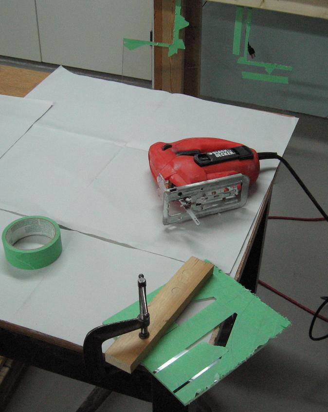
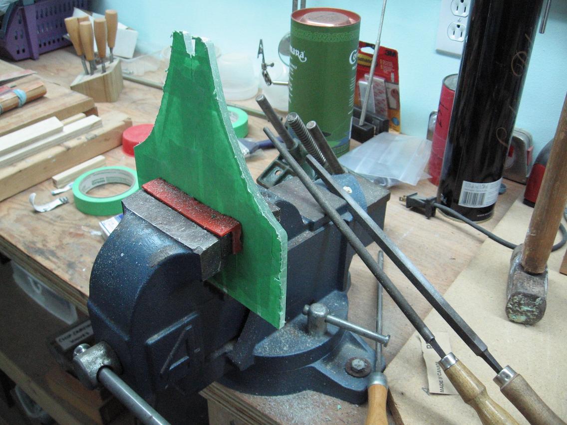
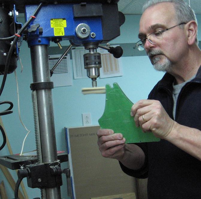
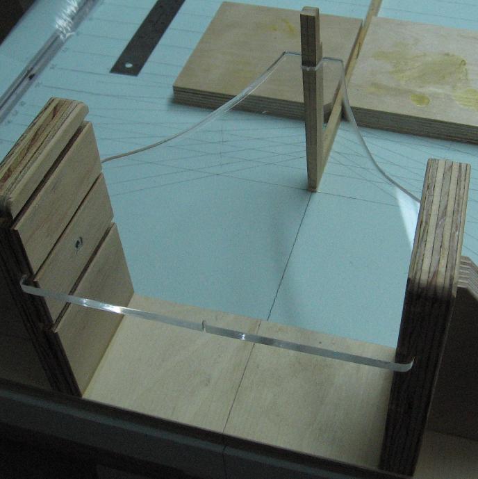
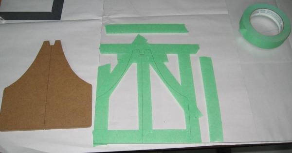
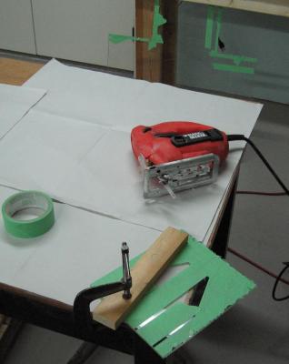
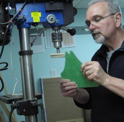
I also worked on my new fangled Plexiglas goose-necked shaped support plates. The Plexiglas was taped (I used painters tape) and the shape traced onto it. The sheet was clamped down securely and the shape cutout using a special Plexiglas cutting blade. If you don’t move quickly enough the plastic melts and sticks back together or leaves a blob of material on the edge that I found was easily removed. The edge was then filed smooth and sanded (various papers, scotch brite pad, micro fine pad). I then polished the edge. The final step was to wash the piece in warm soapy water. I used Dawn dish soap. If it’s gentle enough for oil soaked water fowl it is good enough for my work. (Never use glass cleaner or such products on Plexiglas). Finally I cut out my slots in the wood frame, installed the T-bolts to the table and assembled it in place. Easy, right? Well here is what went wrong… By the time I worked on the second sheet and frame things started to go south. One of the slotted wood uprights on the second frame was installed backwards (slots out) and the space between the two slotted uprights was a wee bit tighter so my second sheet is about 1/16” too wide and needs to be filed down to fit… hence no pictures of the bow support assembly as yet.


-
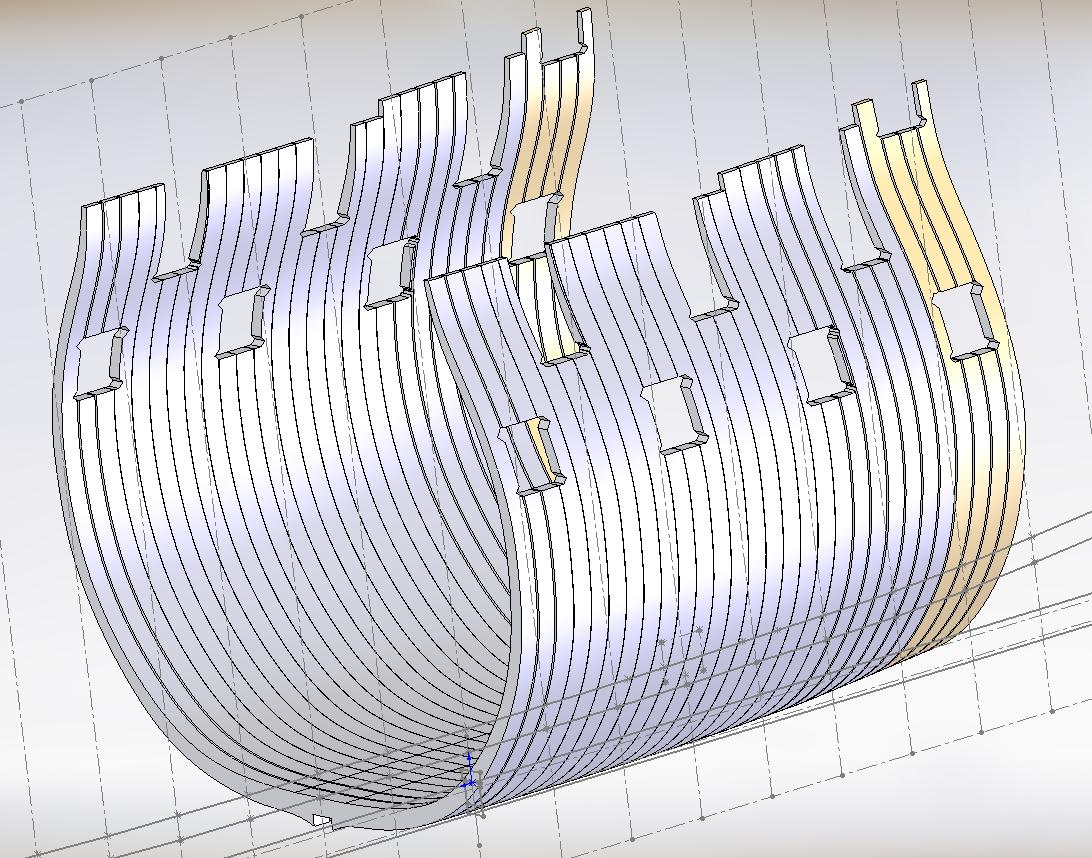
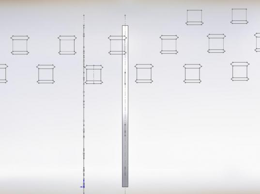
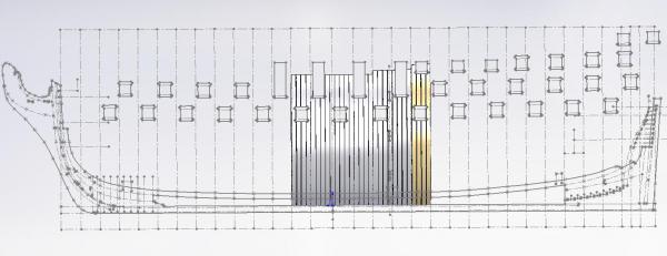
Saturday, 25 April 2015 While merrily working on my frame templates I suddenly realized I was putting in upper scarph joints that likely overlapped the gun ports and sills. I drew in all the gun ports and sills as measured off the plan and the contract. This showed many of my upper scarph joints to be in or overlapping the holes. These were removed and/or relocated. Below is a small sampling (I turned off all other frames) ... you can see the joints in the one frame (all others are turned off to make it clearer)
-
Slow progress drawing up the frame templates. The more I look at the small amount woodwork I've done to date the more I want to start over. I am not completely happy with my joinery and feel with some practice I can do a much better job. I will complete what I've started and then decide if this would have been all for practise, at which point I may then put it aside and do it all over again. I will need to do more joinery practice work on pieces out of the drop pile. If I keep going down this path I may need to grab another bundle of lath out of my son's wood pile!! I also signed up for the Admiralty Models Spring Workshop being held in beautiful Niagara on the Lake on May the 1st ans 2nd This one is on Frieze Painting and Flag Making I know I am years from needing to know this stuff, but when opportunity knocks....
-
timing belts and pulleys
AON replied to Kurt Johnson's topic in Modeling tools and Workshop Equipment
www.gates.com offers a design booklet for their cogged or toothed pulleys and belts that should answer your questions and help with your selection but wq3296 is correct... it will not slip so the safety aspect of the slippage is lost. -
I see with your last photo you have started a new scratch build kit Congratulations! it is difficult to comment on the former when looking at the latter This next kit will take a lifetime but like most you'll get so much more from it then you give.
-
Looks good to me too. I find that when I take my time and think things through, develop the plan, and eventually take a step... I should have wrote down the plan because I forgot a step. So now I write down the plan on my computer because it is easier to reorganize it there then with pencil, paper and eraser. And yet somehow I continue to skip a step! I blame it on age. As you are much younger it might work better for you!
- 23 replies
-
- 2
-
-
- sherbourne
- caldercraft
- (and 1 more)
-
check out the scratch build of Young American by EdT page 5 post 74 I've tried to copy a link but no success.
-
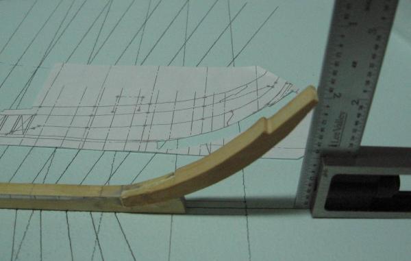
I managed an hour to make another "goose necked" prototype support plate and re-attach the lower stem piece to the keel. In my dealings with Druxey yesterday he had mentioned how the usual fixed position support plate had managed to leave a sun bleached mark on one of his stem/stern post assemblies so another plus to the adjustable support plate height would be to reduce this bleaching effect caused by lighting. I would never had thought of that... I was just attempting to allow the area to open up if I needed to get my big clumsy hands in there!

-
Not much to show this weekend. I completed my transcription of the contract after having had help with the last few terms and phrases from my NRG mentor and then the final push yesterday for 2 hours with help from Druxey. (Thank you very much!) There are 79 typed pages in total of transcriptions, descriptions, explanations and detailed reference sources I can go back to at any time if I need to. Earlier today I took the lower stem piece connection to the keel apart (boxing joint) due to it being slightly skewed. It is thicker than it needs to be to allow sanding to shape but as I will not know if the skewing was too much until the sanding is done, and to do the sanding I need to glue the other stem assembly pieces to it... I felt it was prudent not to tempt fate. Thanks to the forum I found many references on how to dissolve/soften the glue and after having wetted the joint with Isopropyl rubbing alcohol (70% USP), wrapping with plastic wrap and waiting 24 hours it came apart without any effort at all. I had plans to complete my supports and shape the deadwood assembly... but stuff tends to happen and derail the best of plans. Happily this is not a race.
-
His 'about turn' is not very military like. Must be a volunteer.... like me! but seriously... very life like!!
-
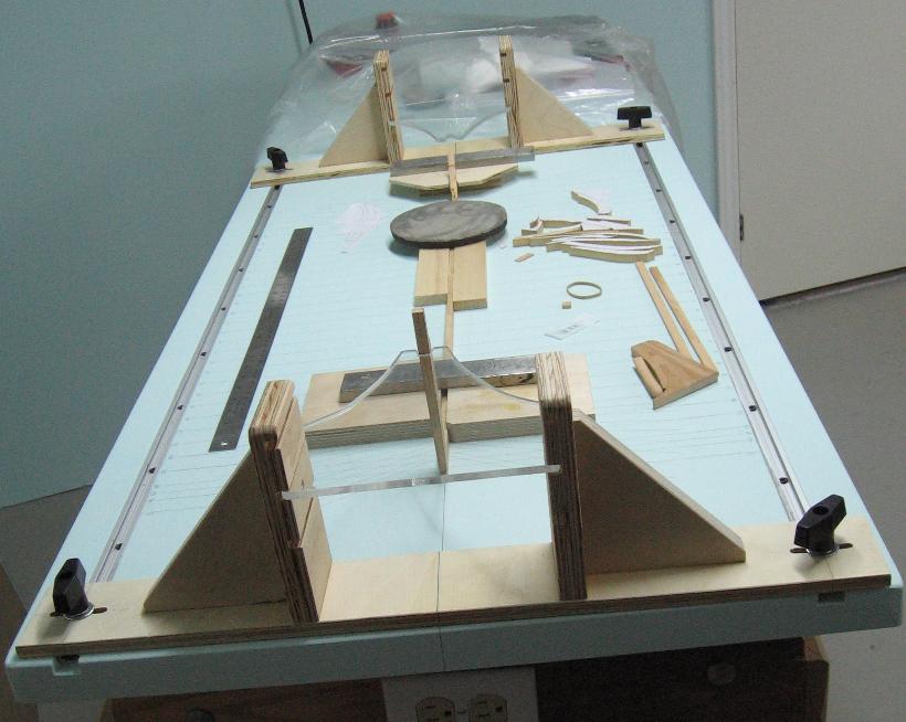
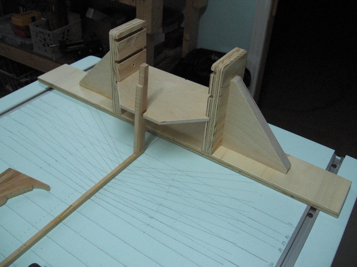
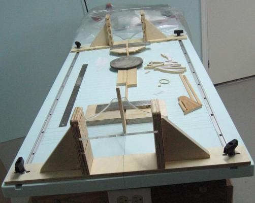
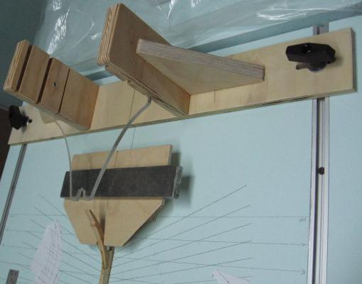
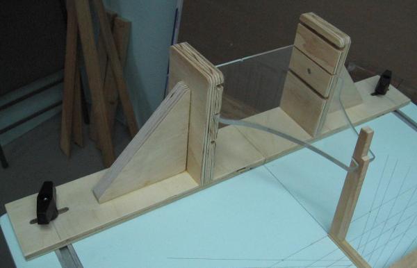
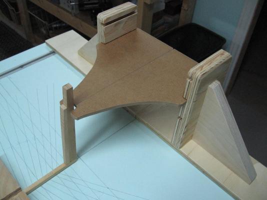
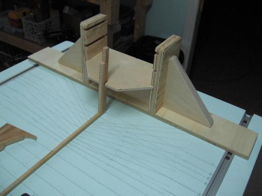
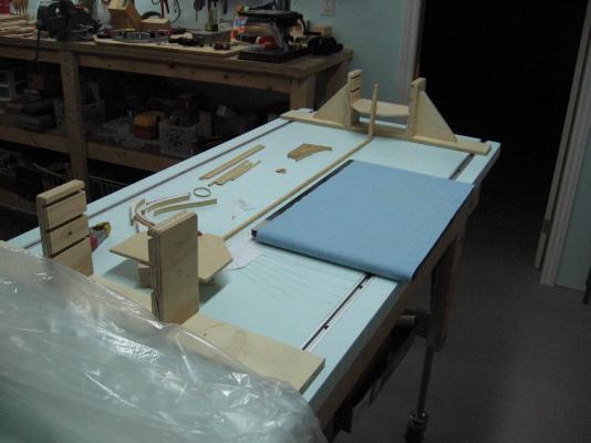
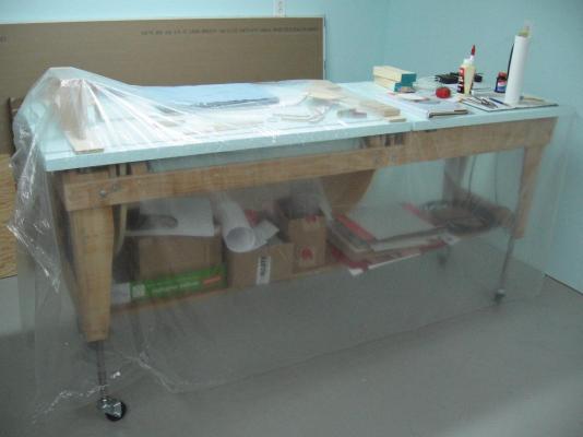
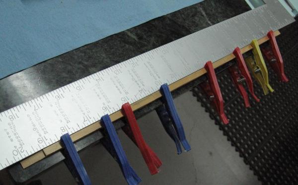
Started making the post supports and have one end assembled less the T-handle clamps to lock it in place on the rails. I made the horizontal support plate adjustable on 3 tiers so if it is in the way I can lower or raise it.... or remove it. Presently the plate is meant to be a prototype (1/4" Plywood) My intention is to make the final version out of 1/4" Plexiglas material of which I have a sheet outside the room with the wood stash. I am not 100% happy with the plate. The bracket can be moved back another 3" on the table top and then the neck on the plate can reach out 3" further to open it up a bit. In the end, as always, the sheet of plastic is pulled over it all to keep the dust at bay. I also glued up some paper onto a piece of scrap for the test mentioned in yesterdays post. It will sit for a few days (as did the real pieces) before I peel the paper off, erase the glue and test wood finish on the glued versus bare wood surface.
-
Just joined in... I like what I see... and I'm ready to learn, Nice work!
-
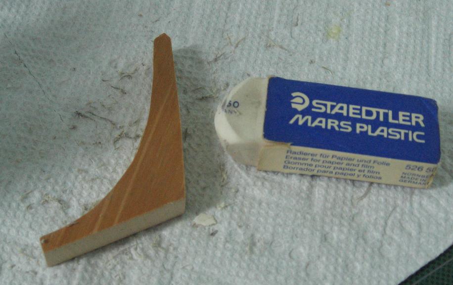
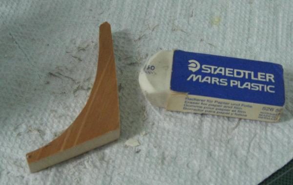
Good morning Druxey, That's no everyday regular eraser... that's left over from my pencil draughting days !!! Rubber cement was used a lot before cut and paste commands on a computer and these erases did the trick... but we had no idea there was a special rubber cement eraser. I'll have to look into it. My darling wife brought up a good point last night... I should do a quick test on scrap to see if after erasing the rubber cement it has not leached into the wood so as to affect any finishing. Regarding the tissue paper... I read somewhere that it should be soaked first, Of course I cannot find that now. I admit I went downstairs and took a look at the assembly and thought about taking it apart after having read your e-mail. I haven't got the heart to attempt to do that. So as much as I unbelievably hate the phrase ... "it is what it is" (I have to go kick myself now ... damn I hate it) I only used the gorilla glue on the copper wire. Everything else is and will be yellow carpenters glue. I believe the 22 ga copper wire may be a waste of time in most places. Roughing up the monofilament line grabs and seems to carry the glue into the hole. This seems better to me. Presently looking at cutting and placing the rising wood and false keel I will use the copper wire for the staples securing the sides of the false keel I also have to make my jigs to hold the stem and stern post secure and perpendicular to the table. Alan
-
Good evening Mark! I have not read The Billy Ruffian by David Cordingly. I do have and did read HMS Bellerophon by Colin Pengelly. I guess I have another book to buy! Thanks. Alan
-
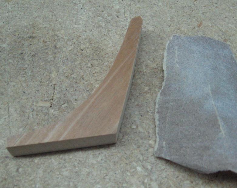
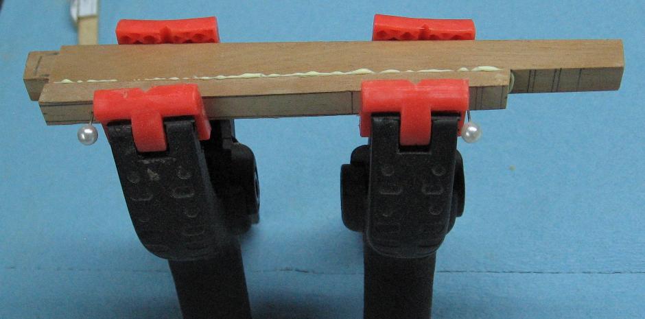
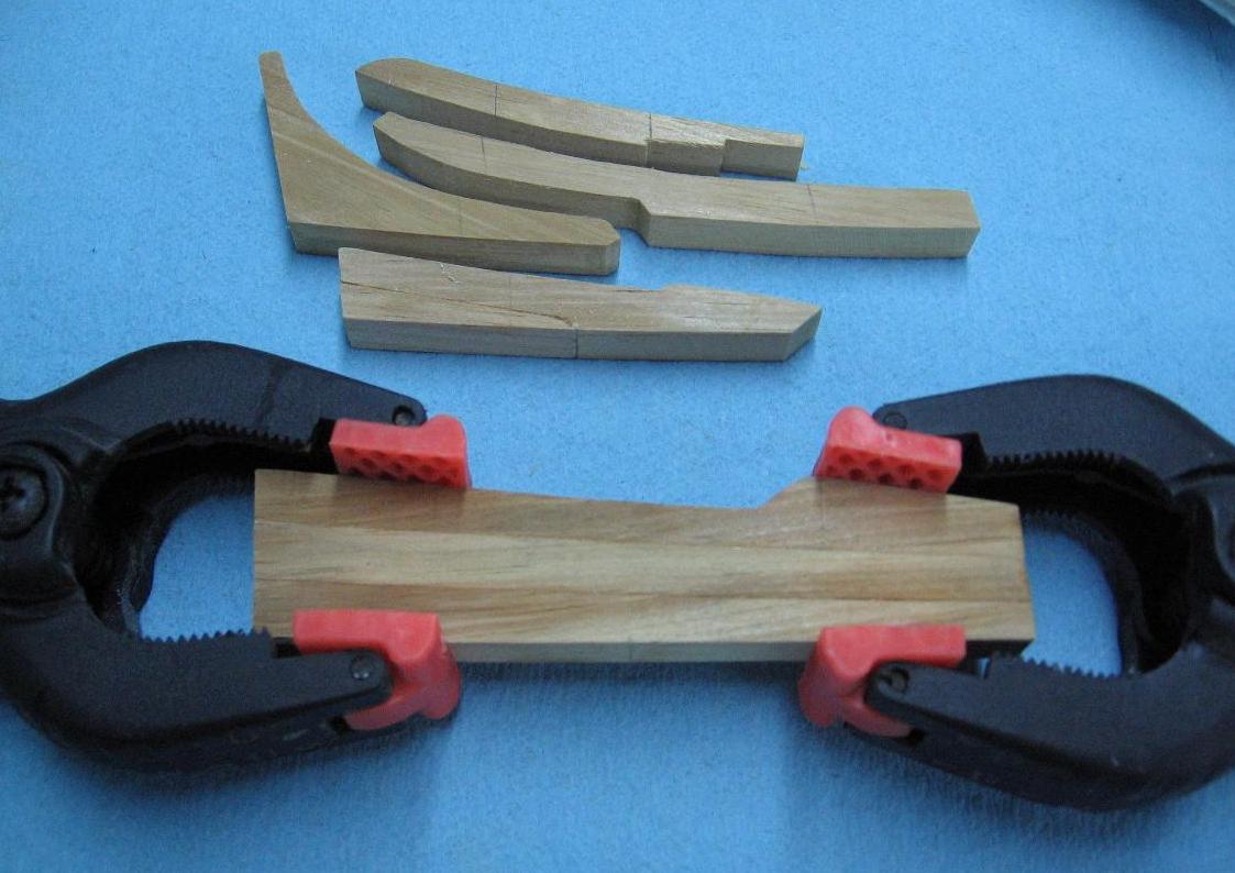
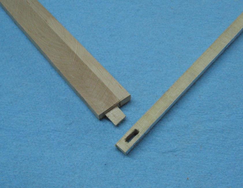
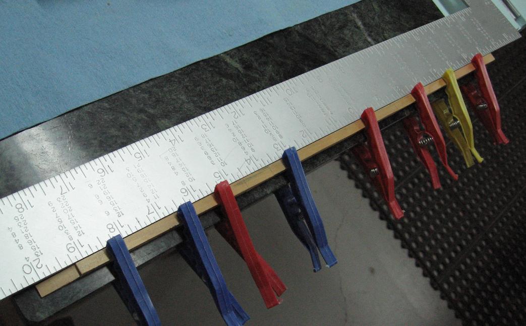
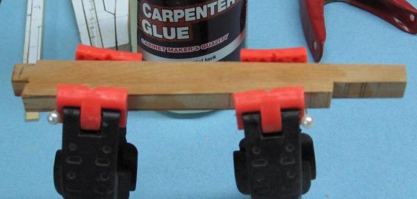
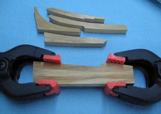
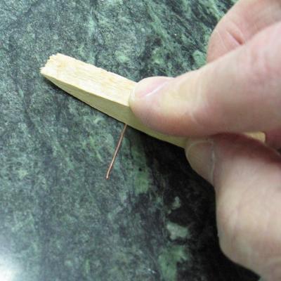
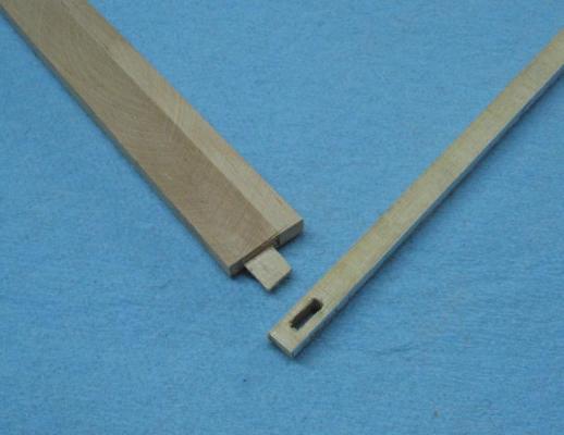
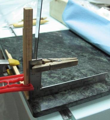
Started gluing parts together today The remnants of the rubber cement were removed by simply erasing the surface…. … and there were paper thin feathered edges from my sander that need to removed by lightly sanded by hand. First piece glued was the Stern Post to the Inner Post. Here are the before and after cleaning pics. I did drill and pin them to assist in alignment. You can see the ball head of the straight pins. The pencil lines are to help me with shaping later on. The stern deadwood was assembled piece by piece, clamping up and letting them set before attaching the next piece. This is where my marble pastry rolling slab came in handy. I set the assembly down onto the slab to assure the surfaces were flush when assembled. I did insert two pieces of copper wire into the stern post assembly to assist in keeping it together. Not sure it was necessary nor that the Gorilla Glue got in deep enough. I tried working the wire in and out but I did not see any glue at the far end. I had to strip the insulation of the telephone wire and then roll the copper wire straight. 22 gauge wire is quite flimsy stuff and easily bent. I cut the mortise and tennon joint in the Stern Post and Keel then assembled them. Clamping up the tapered stern post to the proper angle was a bit of a challenge. I ended up using a few different tools and good old fashion clothes pins. The Stem to Keel boxing joint was eventually glued up and set properly. I did attempt to use the black tissue paper as you can see by the staining on the wood but had no success. I determined it was more trouble than it was worth. I first soaked the paper in a 50/50 water glue mix and after numerous tries place it on the joint surfaces. Quite a few pieces tore apart in my fingers/tweezers. When I finally got around to attempting to put the keel and stem together the paper scrunched up on me. I took it apart and tried again with new pieces… then had more of the same trouble. After two more attempts I said to myself “screw it”. I also glued up the remaining sections of the keel; clamping them to the marble pastry slab and setting them against a straight edge…. sans tissue paper.


-
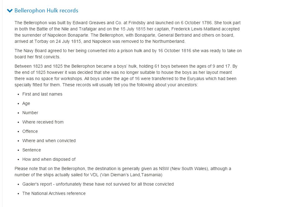
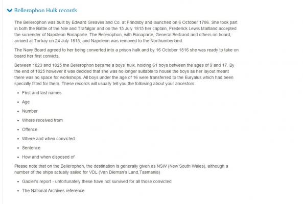
Good morning world. Itching to get started this morning but cannot make noise while the better half sleeps. Today I bite the bullet and begin drilling, pinning and gluing. My darling wife (the super sleuth) made a discover yesterday while working on her geology hobby tracing her and my family. Seems one of my Irish ancestors (James Flynn) was sentenced to serve his term on a prison hulk. While searching for him she stumbled on a 7 year old boy (William Flynn... no known relation) serving his sentence on HMS Bellerophon. In her end years the Bellerophon (later renamed Captivity) was used to hold young boys as prisoners! I always imagined these were military prisons, holding AWOL and mutineer sailors and such... was I wrong or what. The attached reads 9 to 17 year old boys but William was 7 and he was recorded as having been there once before!!!
-
verrrrry nice!