HOLIDAY DONATION DRIVE - SUPPORT MSW - DO YOUR PART TO KEEP THIS GREAT FORUM GOING! (89 donations so far out of 49,000 members - C'mon guys!)
×


AON
-
Posts
2,868 -
Joined
-
Last visited
Content Type
Profiles
Forums
Gallery
Events
Everything posted by AON
-
 Richard, Thank you for the link! Mike, I see the felt used in David Antscherl's volume 1 of The Fully Framed Model Alan
- 968 replies
-
- 1
-

-
- hahn
- oliver cromwell
- (and 1 more)
-
I seem to think this may be the first time I've seen anyone actually use tissue paper in the scarph joint. Most that want the joints to stand out use blackened wood glue. Very interested in hearing how it holds up.... or you've seen it used before?
- 968 replies
-
- 1
-
-
- hahn
- oliver cromwell
- (and 1 more)
-
Are you suggesting I move the Stemson to Keelson scarph aft? It was one of the very few shown on the original plan. I understand the shipwright used the plan as a "guide" and followed their good judgment while keeping to the contract. I must admit making that change does look better. seems like a visit to NMM this evening is in order ... followed by a revision to my revision.
-
Relocated the Keelson scarphs after having looked at the plates in Ree's Naval Archetecture and Cyclopaediaie Vol3 (which were the same) of the normal length 74 (180 feet) and a shorter Frigate of 38 guns (154 feet ) Dwg attached revised PLAN_Keel + Posts layout.pdf
-
Thank you Mark ( I know, I've been following). 1:64 is definitely the smallest scale I dare attempt at this stage. On another note I have been advised my Keelson scarph joints may be located incorrectly. The contract reads that the Keelson shall be constructed of not more than 6 pieces and that the scarf joint is 5'-5" long It however does not say where they should be located and the Arrogant class ship at 168 feet long (stem post to stern post) is shorter than any references I have for a 74 gun 3rd rate ship of the line that show locations. I am certain the shipwrights didn't need to be told where to put them, but alas, as a Sea Cadet I was a Boatswain (Bos'n) not a Shipwright. It was suggested via PM that the Keelson joints should be half way between the Keel joints (which were shown on the ship plans) and that they should not fall under a Mast Step. I will relocate them per these guidelines and re-post. Thank you for the help.
-
Red Green (google him) always says " if they (women) don't find you handsome they should at least find you handy" You may not think it is a good looking fix but as a Red Green fan I think you did an awesome job.... and no duct tape!!! Seriously now... good job, and glad to hear you enjoy yours as much as I do mine!
- 968 replies
-
- 2
-
-
- hahn
- oliver cromwell
- (and 1 more)
-
I practiced laying out and 3D modelling a few frames once again (re-learning what I decided I would do some time ago) and realized another mistake / misunderstanding of the contract description and so my final template will look slightly different than my earlier attempts. I will be working on these many, many profiles to make the 3d of the hull, slice it up into the frames, etc and then create the 2D template for each for cutting and building. I completed the Keel, Stem and Stern Post assembly drawing (see attached) and feel I can begin this part of my build. My drawing has four copies of the same detail. - One to remain untouched for reference - Two to be cut up for templates - and the last one as a spare copy PLAN_Keel + Posts layout.PDF I also made a visit to my son and liberated yet more lathe from his scrap pile as I read on the forum you should have twice as much wood as you calculated to cover cutting loss and scrap. It is presently laid out flat in the basement acclimatizing. I will be practicing my scarph joinery on scraps and will not attempt it on the good pieces until I get it right. I find I'm feeling a bit excited and very nervous at the moment... first cut jitters I suppose.
-
I would suggest a test of the tool and your skill on a scrap piece so you can determine if it is adequate for you. Might take some practice/ multiple attempts before you can decide.
-
Ed I had visited your build earlier this week and made a note to come back and start at the beginning Came back at just before 10 am this morning and it is now approaching 4 pm Thank you I have learnt so much today love the pins love the copper wire love the mono filament love the blackening love the....... everything about your build. I want to be just like you when I grow up and that is saying a lot because until now I never wanted to grow up!
- 3,618 replies
-
- 6
-
-
- young america
- clipper
- (and 1 more)
-
1:64 in my mind will not in any way be a small model but, for me, when I hear the name Bellerophon I cannot imagine the injustice of reproducing her image in any shape less than grand. My former crew and the alumni of #141 RCSCC Bellerophon would understand completely. I pray I am up to the task. Although I have been trying to rush through the modelling and drawing part (honestly I have, if it weren't for the side projects) the building will in no way be a race. Creating saw dust, wood chips, dull edges on knives and chisels..... I can barely wait to be in the middle of it! (I love building as much as demolition)
-
BUILD SCALE: it will not be 1:48 as this will be too large I will not be able to reach the top of the tallest mast even with my model table lowered completely I printed off three scales on two sheets ($4.25 Canadian per sheet at 36" x 60") Cut them out and set them on my table so I could best visualize the physical size Planted my measuring sticks to simulate height over the tallest mast and breadth over the longest yard 1:64 will fit nicely on the table and 1:72 is the smallest I dare go. I admit to being intimidated by the smallness of some tiny components at these scales Scratch building will be a real test of my abilities I'll need a bigger scrap box. I am going with 1:64 Decision made. I've said it before but it warrants mentioning again Thank you to everyone that has offered me help to this point, Lord knows I need it. I will be starting on creating my templates I imagine this will take some months with the amount of time I can put to this hobby every day. Alan
-
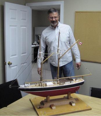
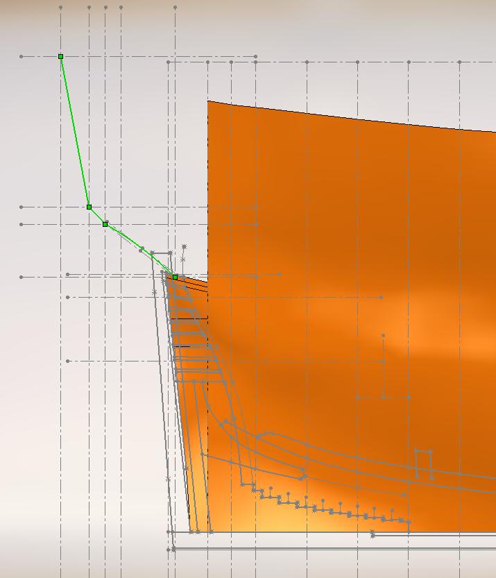
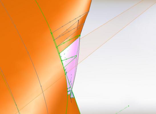
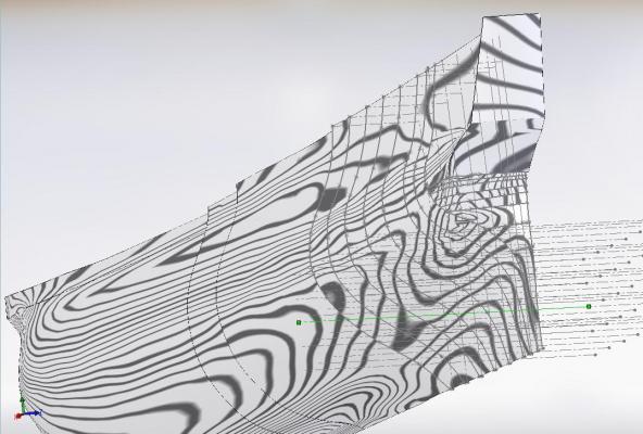
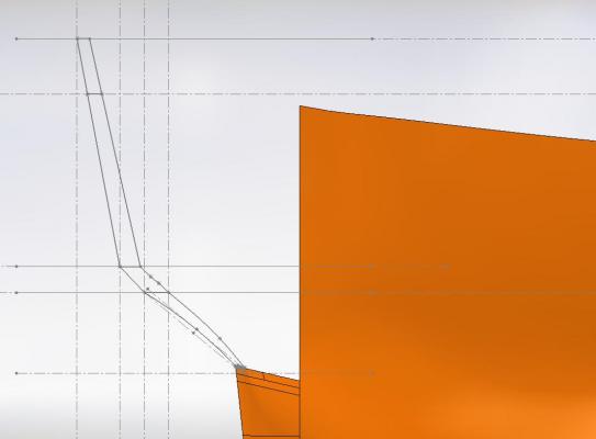
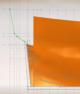
I believe I may have it now ... but I do not feel any smarter (Thank to my ancestors I've got my good looks to fall back on ) Druxey suggested running plank lines or wire frame My NRG mentor suggested buttock lines needed to be followed I drew in buttock lines on my frames and then drew in faux plank lines These showed my loft feature to be bumped out considerably on a couple places I created new 3D profile / guide lines for the pulled in shape and lofted to these It was still, somehow, not quite right. There were still bumps, albiet smaller ones. I needed to divide the features more and create additional lofts of smaller areas to get it to pull in better. The pink is the old shape and the green lines are the new shape before dividing it up more Even after having done this all lines needed manual adjustments to blend better Following is what I ended up with. There are still minor deformations but at model scale and with sanding I believe these blemishes will disappear.

-
Thank you very much for the link Lonelius. I've checked it out three times now I should live so long to make it look as easy as that! his post 4 image #2 really shows what I should be striving for I have a gut feeling that I am making this more difficult than it should be, that there is an easier way to complete this, if my skill levels could only miraculously multiply over night. I am using the loft command to see the outside surface of the timber /inside surface of the outer hull shape It seems this gentleman used the shell command and added thickness for the inner / outer hull.
-
Louie we are then both dinosaurs! Alan
-
I did run some simulation buttock lines (like planks?) tonight and can see issues much lower and exactly in the area you questioned. I made a separate copy and was playing with it but my eyes need a rest and my mind needs to clear. Calling it quits for tonight Try fresh tomorrow. I think I need to break up the profiles more to get them to follow the right curves. Many many many more guide lines required (resembling a wire frame) You are much smarter than I look, and I have a ways to go to catch up to my good looks
-
heard back from my NRG mentor and my stern is not quite right looking at Gils Victory at http://modelshipworld.com/index.php?/topic/485-hms-victory-by-gil-middleton-jotika-172/#entry8107) post #15 - images 7 + 8 They are another two very good references I believe these three lofted sections of my model are possibly wrong but before I jump into making things worse I'll be taking a break
-
Had a busy time the last couple days. Played with the upper transom outer corner some more and have 'flattened' it about as much as I dare. Seems every other adjustment from there makes things worse somewhere else. I managed to create a 5 second animation pan viewing the corner and also a PDF of incremental snaps shots automatically generated from the animation and sent it all to my NRG mentor to comment on. Unfortunately I cannot seem to attach the .avi file here for the forum to view so here is the PDF. lower transom shaping.pdf I also manged (after considerable time ... it ended up being easier than I made it out to be) created a 36" x 60" sheet for my drawings in Solidworks. I added 2D images from the 3D model at 1:48 and 1: 72 scale to be printed out to scale on Monday so I can better visualize. HMS Bellerophon scales 1_48+72.pdf That will be when I finally get off the fence and decide once and for all on a build scale. I am / was (?) wanting to build 1:48 but am suddenly coming to realize the massive size this would be. Possibly 1:72 might be more accommodating.
-
good photo from forum at: http://modelshipworld.com/index.php/topic/2926-hms-bellerophon-1786-by-fake-johnbull-amativictory-models-172-vanguard-kit/page-2 post number 20 picture number 6
-
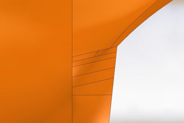
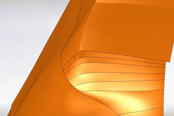
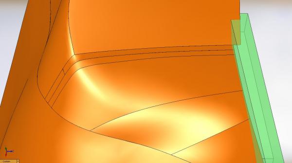
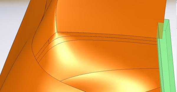
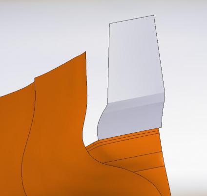
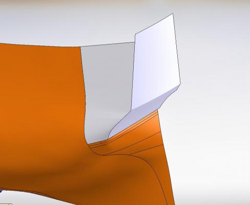
I looked at images of the Bellona transom which was better than most images in books I have Then I adjusted the radius as much as possible, I believe, to reduce the sharpness in the turn at the corner Following are two images, before adjustments and after Druxey, is this "more better?" (as the young'uns say) Alan
-
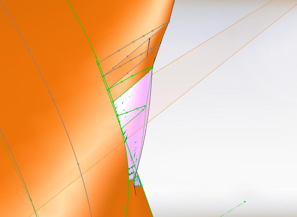
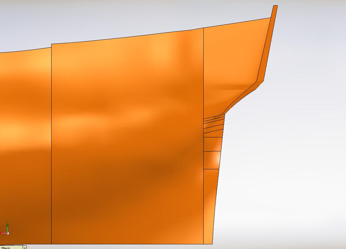
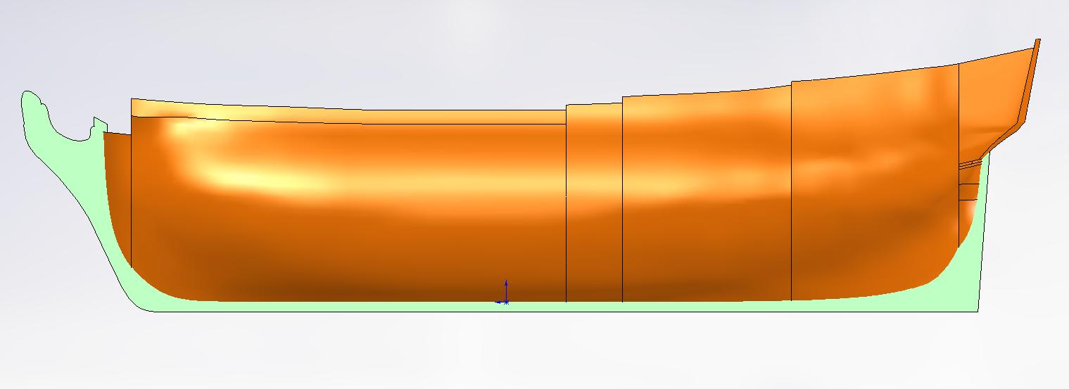
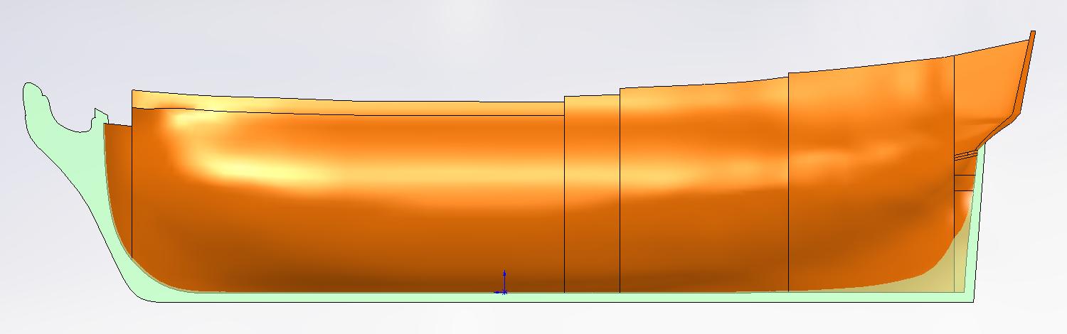
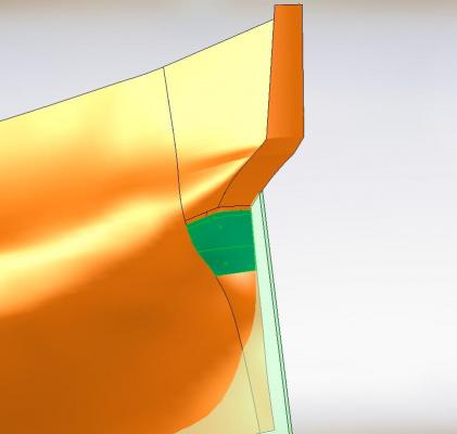
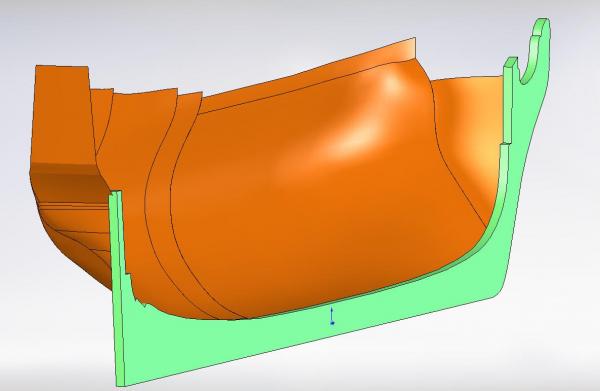
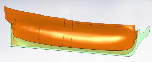
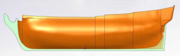
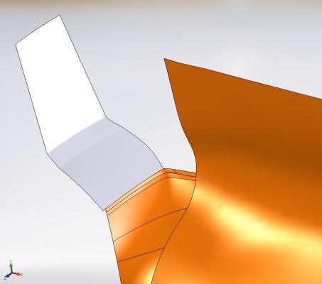
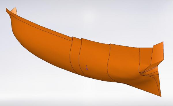
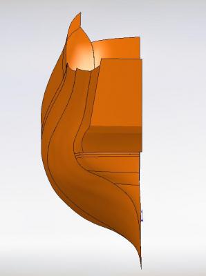
Thank you Druxey I'll have a look at some photos from forum builds and books and then play with it some more. Meanwhile I had extruded my keel and post sketch to the maximum thickness of 1-1/2 feet. You can see the hull shape at the stern disappears into it prematurely. This is because the stern post is not a constant thickness but notched away and tapered. Same thing at the stem post but not as dramatic. I included a couple snap shots with the keel and posts made a bit transparent so you can see where the hull disappeared to.

-
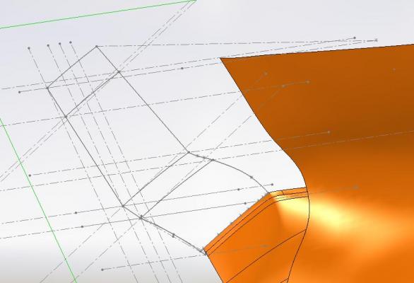
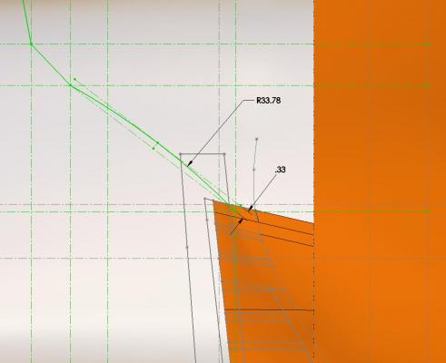
I created new planes at the different deck levels where the transom direction (shape) changes and drew my arc's in. These ended up being 50.5 ft radius. This was accomplished by inserting a "point" on the plane and then mating it via "pierce" to the earlier transom line from yesterday that passes through the plane. I drew a center line on the plane passing through this point and then offset it the distance to the hull as measured off the plan. Width measurements were: roundhouse deck level = 20 feet quarter deck level = 24 feet upper deck level = 26 feet The arc was trimmed back to the centre line on one side as I would only loft half the transom as the extending lines might confuse the loft feature. I then added yet one more plane at the highest most elevation of the centre stern frame under the rail at 52'-6" and added another arc. I then "connected the dots" of the extreme outer ends of the arcs using 3D sketch (I got this idea from Don's posting above) This required some 3D manual fine tuning to blend the line into the shape of the hull Once I had that where I thought I should stop I used the Loft Feature to fill in the shape. I then added a few extra lines to allow me to lofted in the shape of the missing upper port aft part of the hull. Now I need to complete the keel and posts.

-
The refit of the schooner Charlie is complete. I finished my workroom (installed the missing door trims) on Monday Planed down an extra door jamb and ripped to size to make the trims for my modelling table edges. They are installed (glued, pinned and clamped at the moment) but not complete. They will need sanding and the table requires painting in the next few days to be complete. So I finally find I am back on my Bellerophon. I am looking forward to beginning the actual scratch build of this ship but must finish my plans first.... completing my 3D model to create and print my cutting templates. After careful study and measurements off the ship's plans I have decided how I might complete this area. I created yet one more plane on the sheer plane to layout the transom outline as measured. The lower transom has an arc or radius to it. You can see in my layout I simply drew a line between the two outer points, offset the line 4" (as measured) and drew a three point arc. When looking down from above the upper transom has a 12" deep arc from sheer line (center line) to the outside (as measured). Next I will complete the profile of the upper transom and then attempt to create the lofted feature and add it to the rest of the 3D model. As the sun has risen well above the yard arm ... and this is the end of 2014... I will slowly make my way to the wardroom to commence celebrations and so I wish everyone a Happy New Year!
-
thank you for sharing Mike!
-
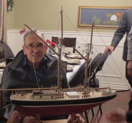
Friday, 26 December 2014 I am proud to announce that Charlie was successfully delivered to John, the owner, by his family on Christmas Day. He was reported to have been quite surprised and very happy. With that off my mind I can bid this build log farewell. A special thank you to all that followed on the journey.... time to get back to my Billy Ruffian! Hope to see you there in the near future. Alan
- 129 replies
-
- 10
-
-
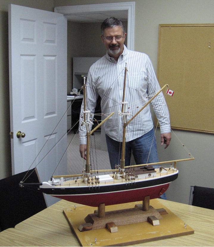
Tuesday 23 December 2014 I snuck through the side office door and set her on the table then had a co-worker call him to the room... all a surprise! Delivered in one piece... that is a weight off my mind. With his permission I've posted the image of his first sight of Charlie below I hope to receive a photo of the father-in-law's expression at Christmas. Alan