HOLIDAY DONATION DRIVE - SUPPORT MSW - DO YOUR PART TO KEEP THIS GREAT FORUM GOING! (89 donations so far out of 49,000 members - C'mon guys!)
×


AON
-
Posts
2,868 -
Joined
-
Last visited
Content Type
Profiles
Forums
Gallery
Events
Everything posted by AON
-
 Druxey That has been my experience with Wikipedia which is why I looked elsewhere (a bit late but before the deed none the less). The decision was made and I think it will look much better for it. Alan
 -
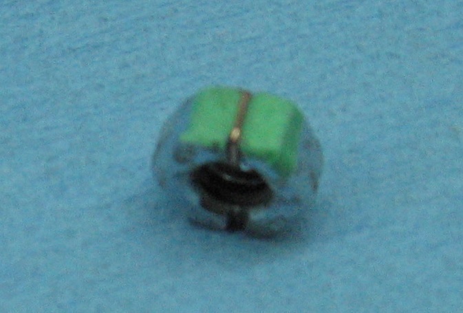
Don Copper staples were the wrong scale, and yes, I want to try to do it all from scratch. Mark, Yes, she was coppered and I foresee having a small portion done on one side only.... a reverse breakaway showing layers.
-
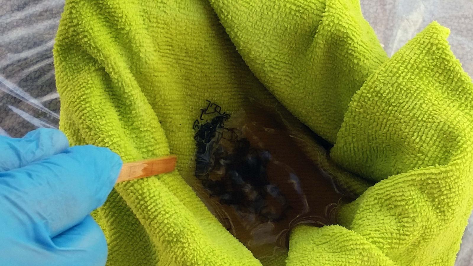
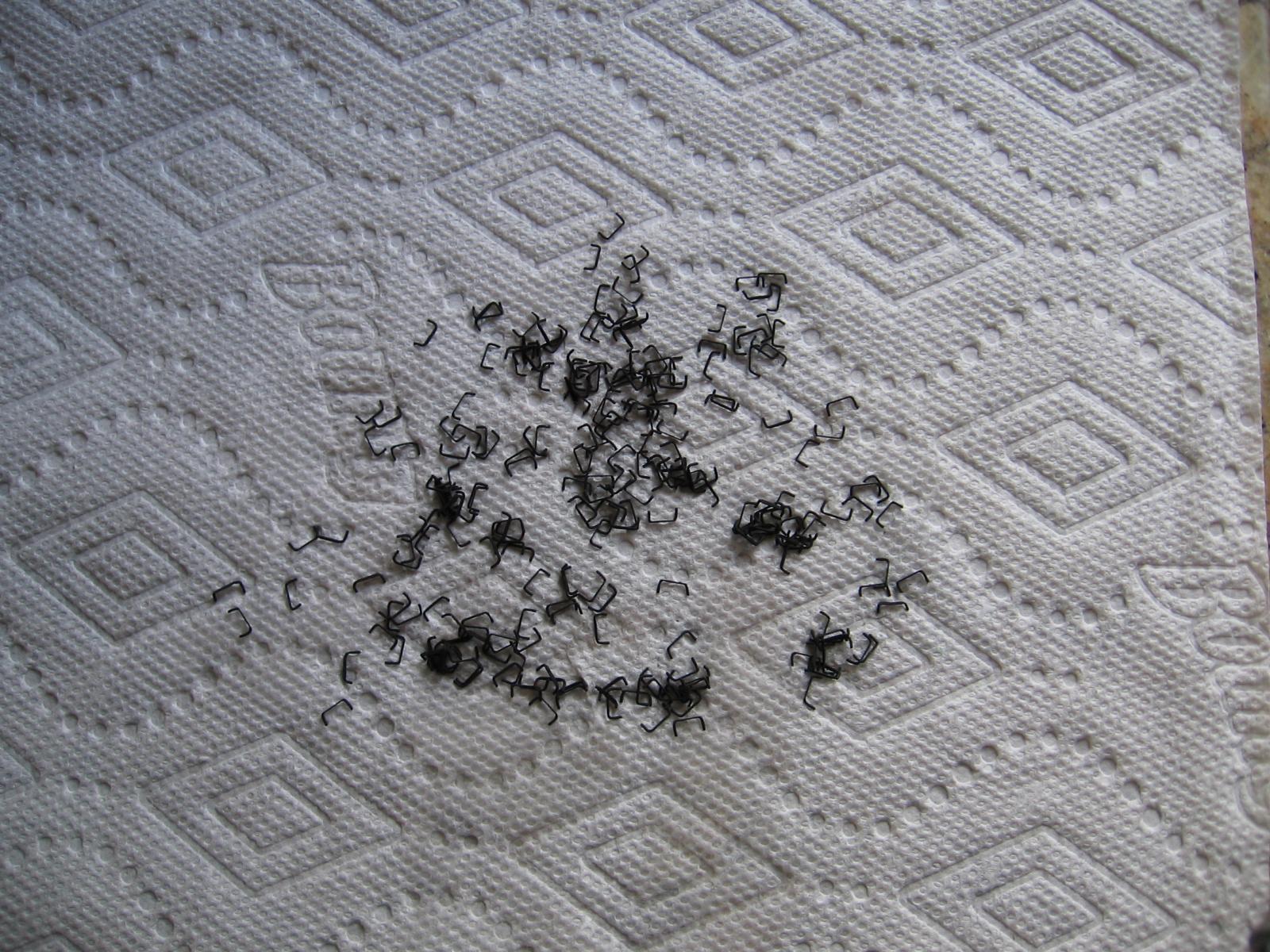
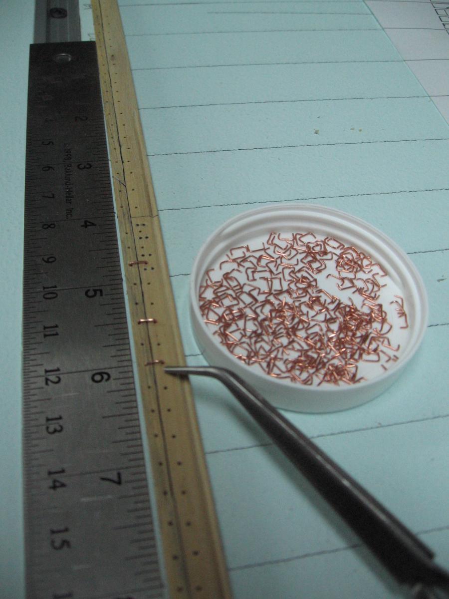
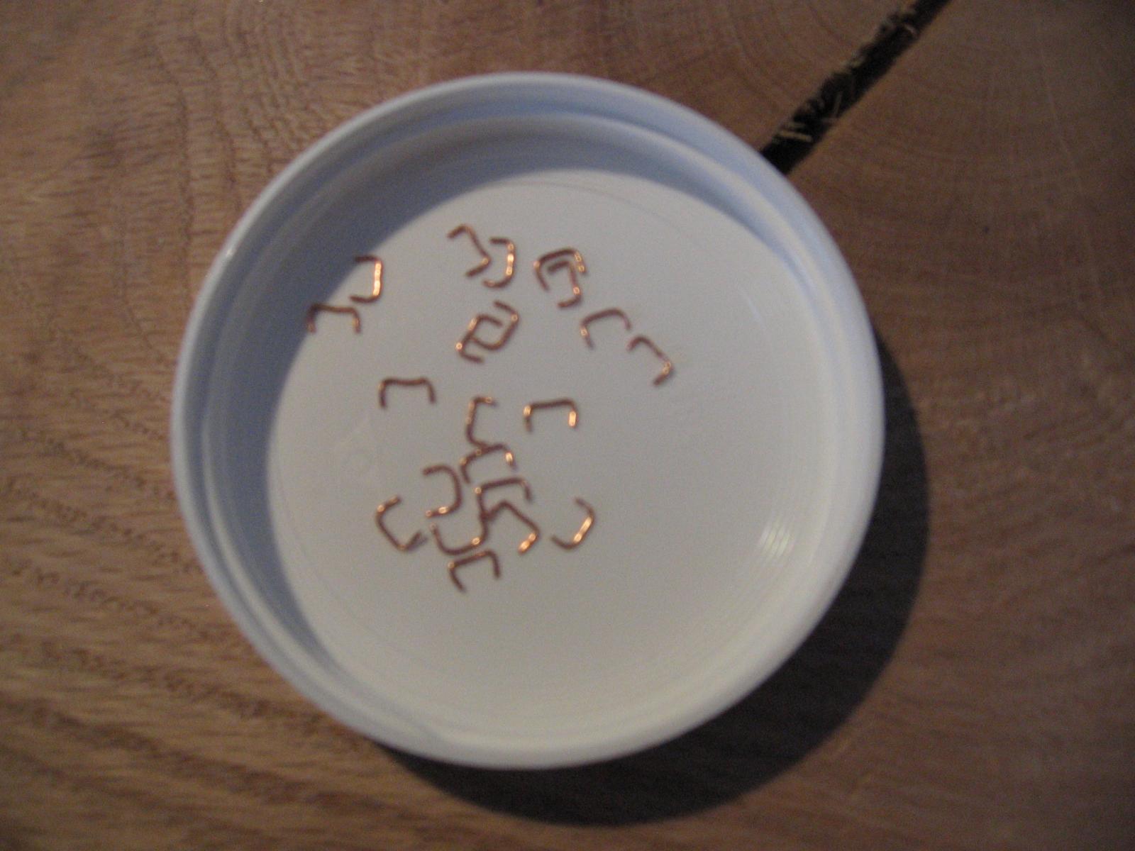
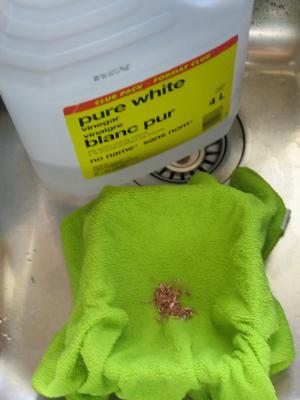
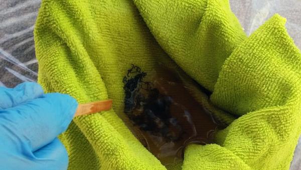
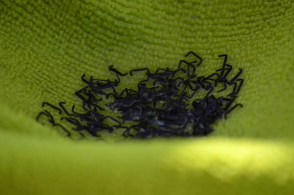
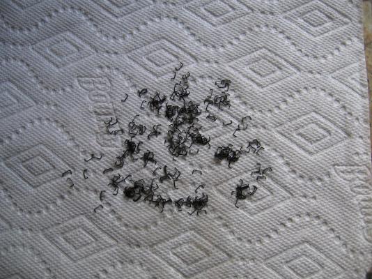
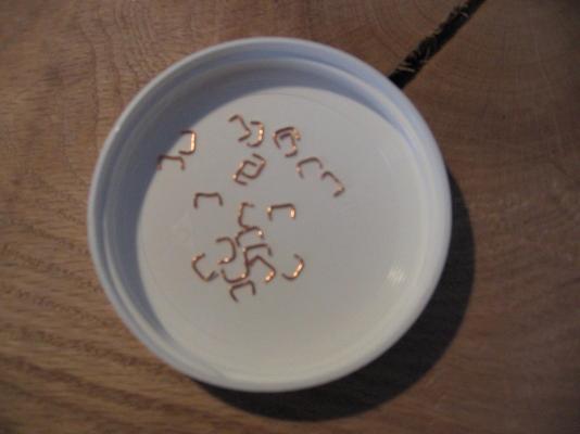
Sunday 17 April 2016 Decision made while out spreading the fertilizer on the lawn. I went and assembled a copper staple to the keel and noticed two things... 1. it was lost against the wood. Very difficult to see. So they will be blackened. 2. Flattening them also caused them to stretch a bit from 9" to about 10-1/2". This means I will need to slot one of all the holes a bit so the are not deformed during installation. Blackening with Liver of Sulphur (LOS) 1. Cleaning. They were washed in white vinegar and rinsed in clean running water while in the cloth. I draped the cloth over an old mushroom plastic container from the grocery story to keep them from washing away. 2. Blackening I did this outside in the backyard. One set of rubber gloves! A very small amount of LOS (one small rock) wrapped in plastic wrap and pre-crushed to smaller almost powder pieced. This was dumped into the empty plastic box. Steaming hot water poured into the disposable container. Stirred up a bit to dissolve. It turned a muddy colour. I was standing down wind. My darling wife with her fancy camera were standing up wind. It smells bad! (REALLY BAD) Placed the cloth with the staples into the box. Moved them around a bit with a wooded stick. Pulled it up occasionally to see the colour changing. It did not take long. 3. Rinsing First rinse was in yet another container with cold water and baking soda mix to stop the LOS chemical reaction. Second rinse was under the tap with cold running water. 4. Drying Staples spread out on paper towel to dry. I did pat them down a bit. 5. Clean up Now I have 240 staples to install.
-
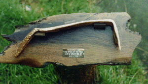
Unfortunately my little camera does not have a macro feature My darling wife was going to get her super dooper do-it-all camera but decided to try the camera on her new fangled do-it-all cell phone. It is a sad day, her phone camera is better than what I am using. Yesterday was a beautiful day in southern Ontario, ruined by spring time yard work and summer-izing the snow blower, taking up the yard furniture from the basement. Spent the afternoon flattening the staples. Today I intended to blacken them as I read on Wikipedia that they were iron. The photo I posted earlier from HMS Invincible (1758) states they were copper as do a number of other sources. One other states they were iron unless the ship hull was copper sheathed in which case the staples were copper to avoid corrosion of the iron. The entire fleet was not coppered until after 1781. In 1783 a mixture of copper-zinc was used to manufacture the hull bolts to avoid corrosion. HMS Bellerophon was ordered in January 1782 and launched October 1786. I must decide, today, whether to blacken them regardless for aesthetics, or leave them to tarnish naturally over time as copper.

-
Sometimes the obvious is the most difficult to see. As you had said earlier... you have double frames and the "flush" sides are "cheek to cheek". I have been looking at single frames (my build plans) for so long and imagining what I should do that it clearly escaped me. You just taught me something else!
- 649 replies
-
- 7
-

-
- dunbrody
- famine ship
- (and 2 more)
-
I hesitate to say.... but possibly the very low support should be taller to assist in keeping the frame perpendicular and square... not speaking from experience as I have yet to do this. Just seems natural that the tall frame needs a tall support. Now, having said it, you have still taught me quite a bit in a short time. Thank you.
- 649 replies
-
- 5
-
-
- dunbrody
- famine ship
- (and 2 more)
-
I suppose I am not so shocked that you admit they (rarely) happen as much as I am delighted you copied me! (yes, I spotted it)
- 641 replies
-
- 2
-
-
- greenwich hospital
- barge
- (and 1 more)
-
Thank you for being so considerate and building in the error! I feel better already.
- 641 replies
-
- 6
-
-
- greenwich hospital
- barge
- (and 1 more)
-
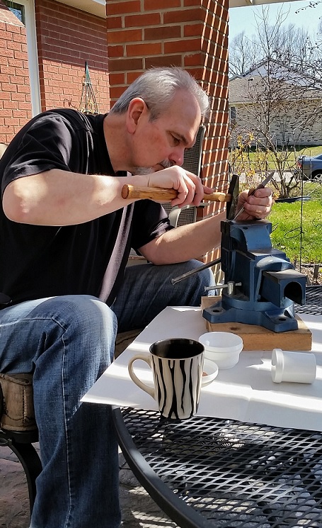
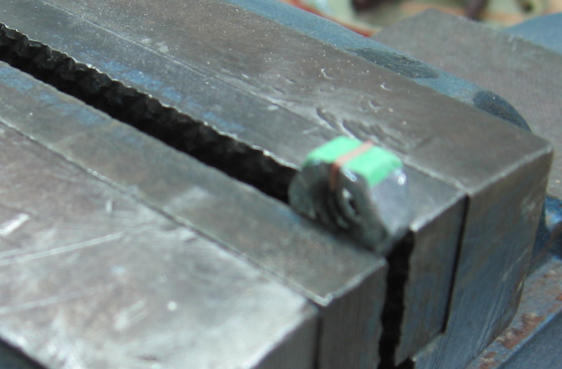
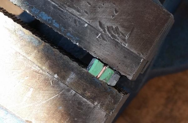
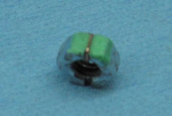
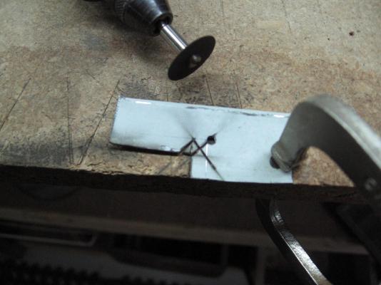
Tuesday evening 12 April 2016 Made a couple "anvils" using a 1/4" hex nut. I had a few sides to work with! Applied painters tape to be able to draw a straight line from side to side to mark the cut points. Marked off 9" width of staple. Used my dremel and a cutting wheel to notch the nut sides. Fitted a staple to test... it took a couple extra nicks to get the depth correct to hold the staple properly. Set it up in my vise and gave it a "wack"... more of a gentle tap or two. They look darn good to me. I apologize for the poor pics. My little Cannon Power Plus A520 doesn't seem to focus well on the tiny stuff (or is it me???) Environment Canada announced this morning that winter is officially over for southern Ontario. No more snow... if you can believe a weatherman. Should be blackening this weekend.

-
Good eye! Yes they are still 1-1/4" (0.02" or 0.5mm) round but the exposed portion will be flattened. I experimented with a small hex nut of almost the correct width and some taps with a hammer. it was difficult to hold but the results were not bad. I will be making an anvil jig out of a larger hex nut, cut grooves on either side to hold the staple and possibly just clamp it flat in the vise as I've done before on Charlie. This way the legs remain round for the holes. That will be my next experiment.
-
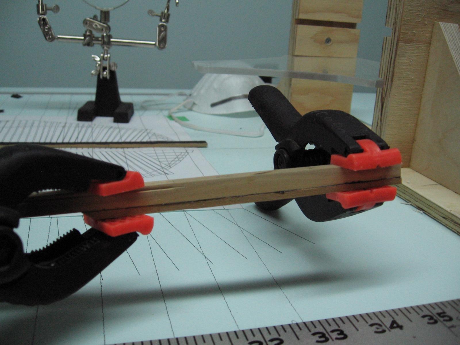
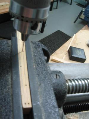
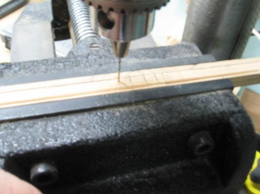
Sunday 10 April 2016 I Just completed 250 staples. By count mentioned earlier I deduced I require 240, so there are 10 extra. I found an quicker way to make them after the first 20 or so, I eliminated the wood form and just used the clamp as it ended up being the perfect width! Drilled all the holes in the false and main keel today. Ended up drilling 4 more staple locations due to alignments with nails and bolts and scarph joints. So that leaves 6 extra. So in the photo below you will see what 250 each x 9" long (0.1406" = 0.357cm) copper staples look like and see the keels peppered with holes. I partially inserted 3 staples for effect. They are not yet blackened. Still too cold for me to do my first ever blackening in the garage and I dare not stink up the house or the love of my life will have something to say about it. I also decided only two of the offending keel scarph joint bolts absolutely needed correcting and so took care of those. Tried to drill out the one side about 1/8" deep. That did not work as the monofilament line will not allow the bit to bite (too slippery). Ended up gouging out with a flat bottomed bit and filing in the hole with glue and fine powder sawdust. Now I can live with it. Thank goodness I am striving for realism and not perfection! (I haven't the talent for perfection)

-
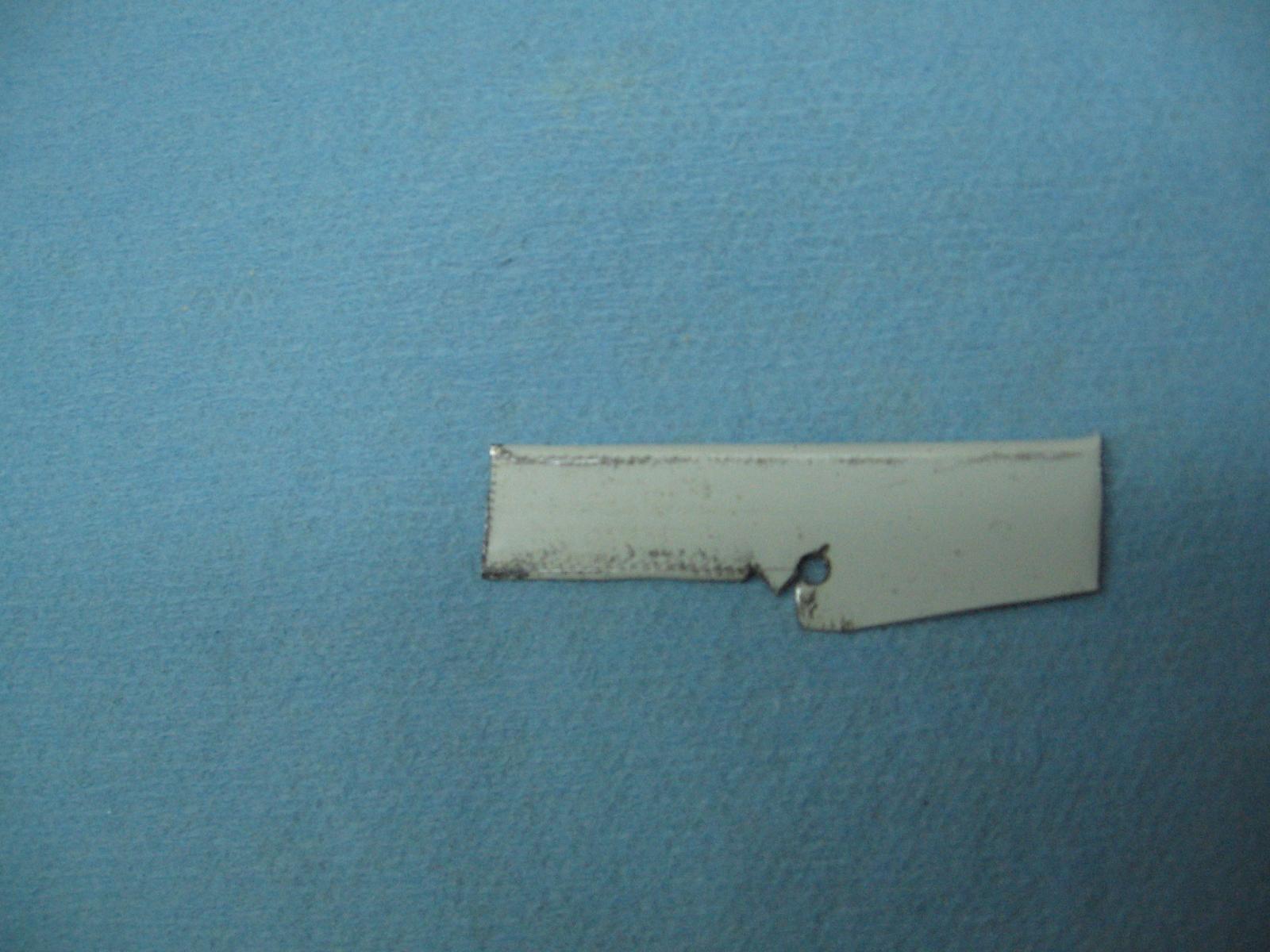
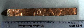
I think you uploaded the wrong image... those pieces do not look like scrap to me
- 649 replies
-
- 5
-
-
- dunbrody
- famine ship
- (and 2 more)
-
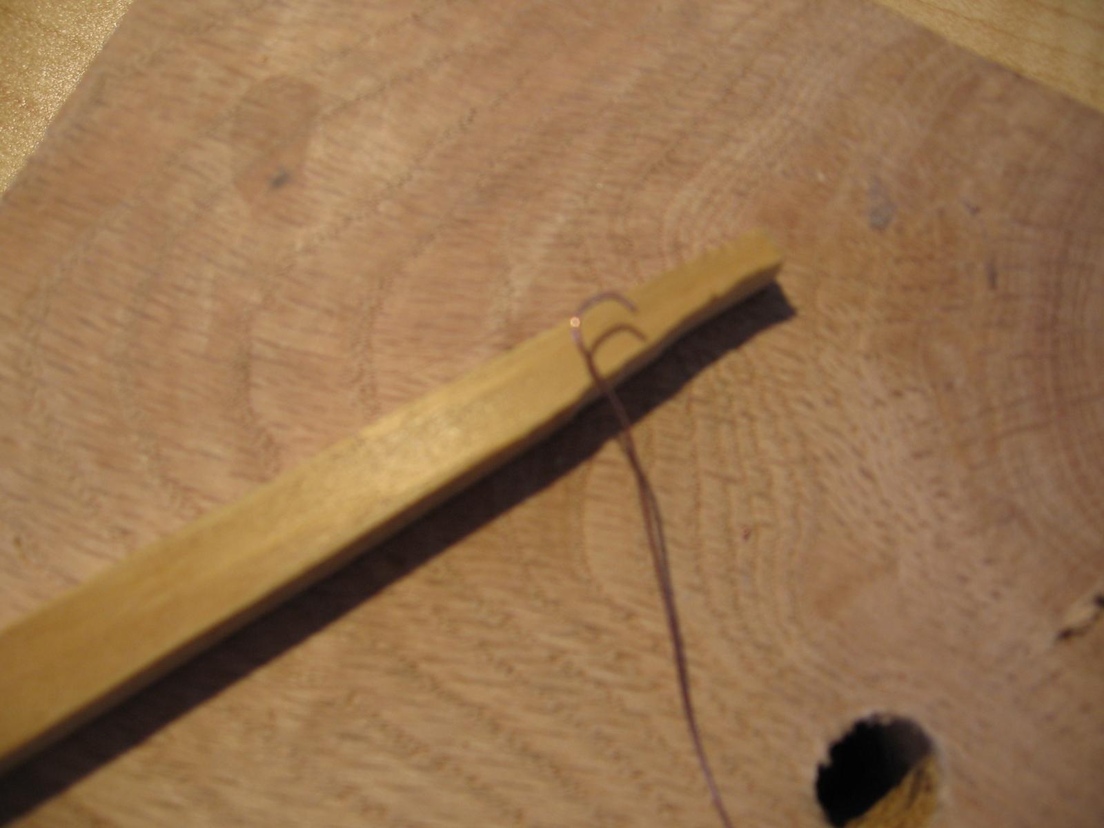
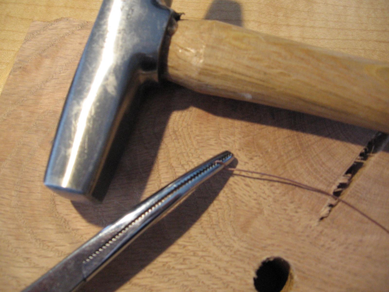
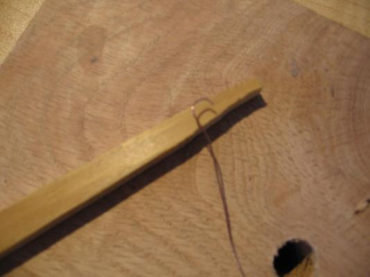
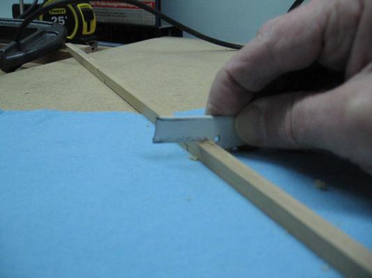
Making staples today. As mentioned earlier the staples are said to be from 6 to 12 inches (15.3 to 30.5 cm) long I've decided to go with 9" (22.8 cm) as it looks the best to my one good eye. After searching and failing to find something to use as a form I decided to use a scrap piece of wood sanded down to 9" or 0.141" (0.36cm) thick. The wire is bent over the wood form, with my fingers. Then clamped and give a gentle tap or two with my 5oz tack hammer to sharpen the 90° bend a bit. Then they are trimmed and stored. These will need to be cleaned before blackened but as I need 240 and I just finished number 60 I'll be at this for a bit. The wallop of snow didn't happen, woke up to an inch or so of snow and ice everywhere (side walks and road). I live on a quiet corner lot and it is fun to watch people try to stop at the corner... they start sliding through, twist there wheels and start to spin a bit before catching themselves. No accidents, just a little excitement in their day. Short lived fun as the sun came out and melted all the ice and some of the snow. They have been predicting the snowfall today. Starts and stops. I hope it just passes over.

-
boring from both sides was the first thought when I noticed it! and that is why hind sight is 20/20 I also wished I'd noticed before I'd cut the line as I could have easily grabbed and twisted them out but I was wearing my magnifiers to get a good look at what I was doing and was focused too closely to see the "forest for the trees" busy making staples... laid out the pattern and found I'll need 240 of them I am on number 34 now will post shortly
-
Thanks guys! I had seen the gel but it seemed most discuss using the rocks so I went with what seemed more popular. May have been a mistake but I'm committed now. Just realized the last group of my scarph bolt holes went wonky on the far side. Possibly the tiny #70 bit was bent a bit by then Not sure how I didn't notice this yesterday I cannot stand the look of it and will need to fix them somehow... time to devise a plan...
-
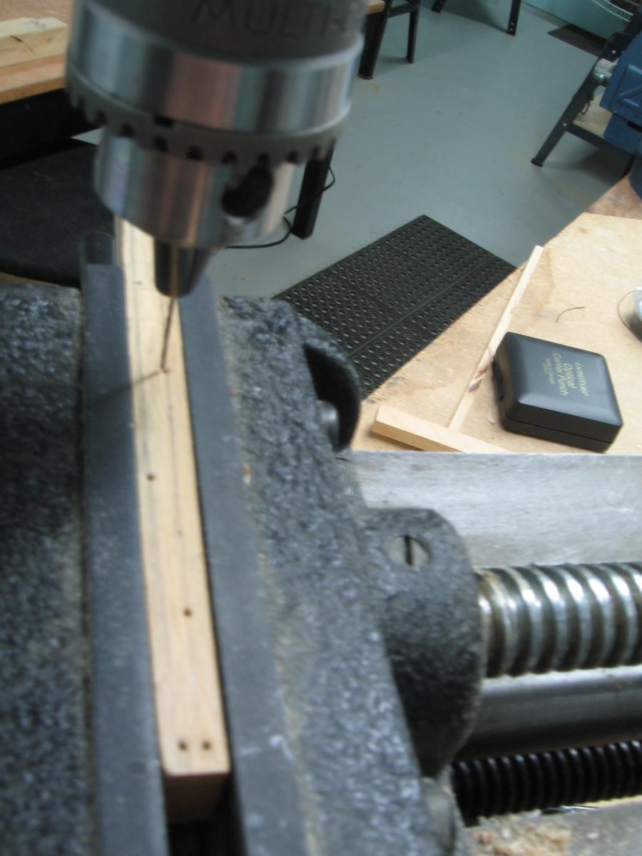
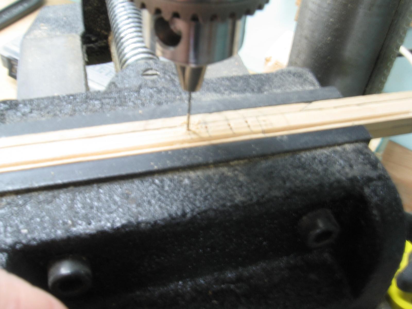
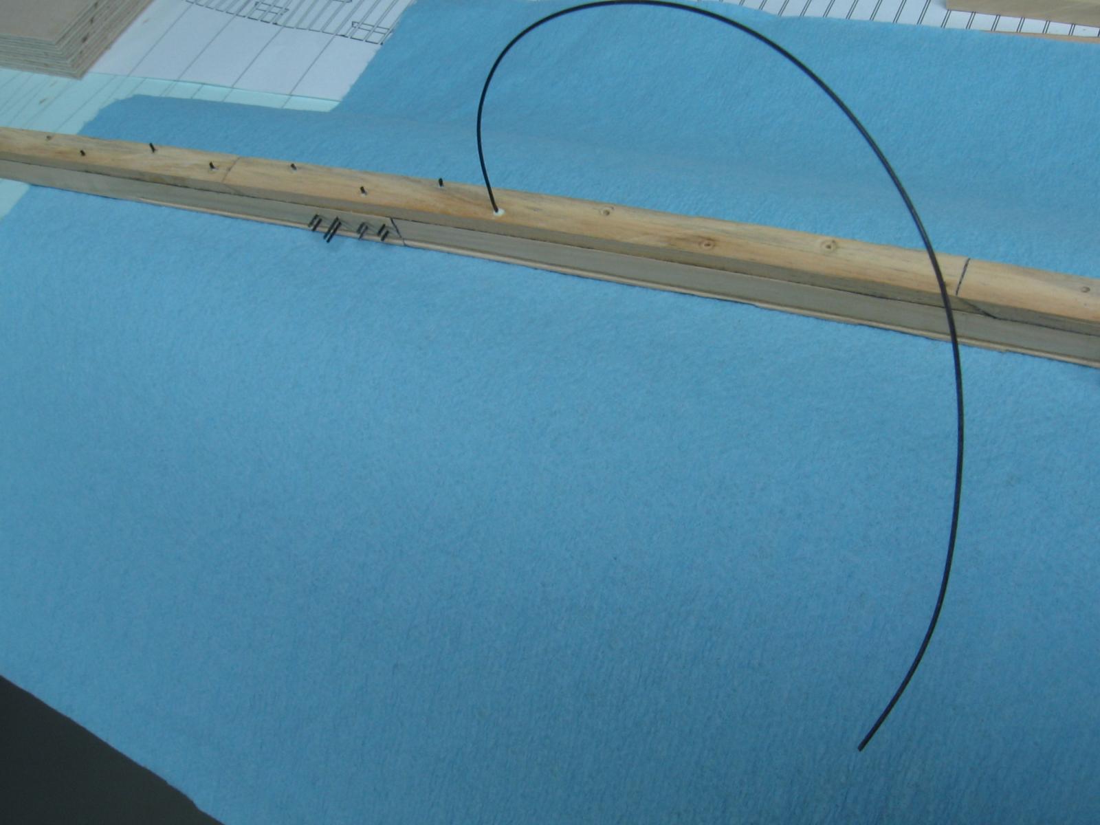
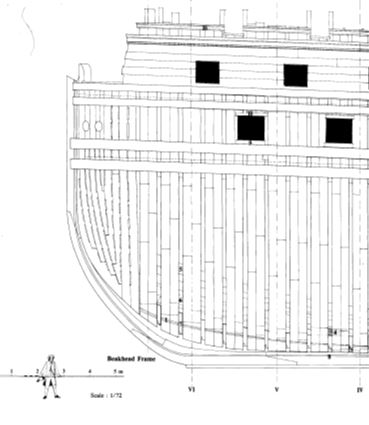
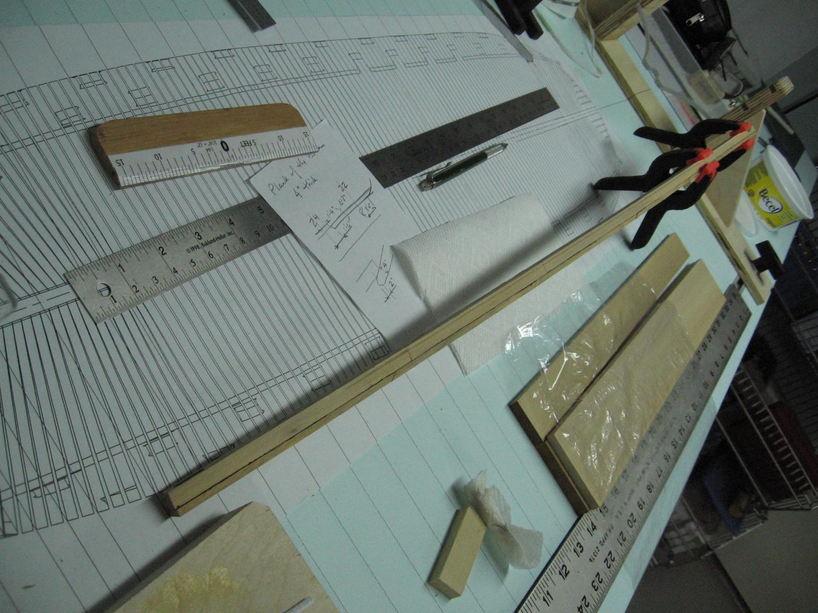
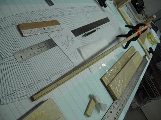
Saturday 02 April 2016 Drilled the main keel scarph joint bolt holes and the false keel nail holes. I used 30 lb test black monofilament fishing line (0.0235 inch [0.06 cm] diameter = 1.5 inch diameter - to scale) for both as explained below. The contract calls for 8 bolts at 1-1/4 inch diameter for each keel scarph joint so my holes are paired up, 2 deep by 4 across, reasonably spaced. It also mentions nails and staples for the false keel but does not give a size. Searching on the interweb I found "An Introductory Outline of the Practise of Ship Building" by John Fincham dated 1821, page 254: the false keel is fastened to the main keel with short bolts or nails about four feet apart, on alternate edges, and staples driven into the side, and let flush, called keel staples, about 2 feet 4 inches apart. So I spaced the nails 4 feet apart and staggered... assuming for scale they are about the same size. I roughed up the line with sand paper so the glue would grip it, applied glue to the line and inserted it through the holes in the main keel. Cut off the length with scissors then pushed it flush on one side. After it was allowed some time to dry I trimmed it flush on the other side with a scalpel.... cutting away from myself I might add. I repeated this for the false keel. I am now going to layout the staple pattern. I have some 0.5mm (0.02 inch) diameter copper wire to be used for this as these are staples and should have 90° bent barbed ends to be driven into the main and false keel. I cannot bend the fishing line so it cannot be used for this purpose. The copper staples will need to be blackened and I pre-purchased a bottle of LOS (Liver of Sulphur) rocks for the blackening process. I have never done this before and have read up to prepare. I was hoping to do this this weekend, outside due to the expected sulphur smell, but the temperature is dropping, snow was falling and we may be getting one last blow through with 15 cm (6 inches) and freezing rain predicted. I will likely just get everything in readiness until I can do it outdoors and get the full experience before I subject my darling wife to a scent only my brother makes claim to. A few photos of the bolting and nailing process...

-
thank you for the photo sometimes the simplest of things is more easily explained with a picture
- 3,618 replies
-
- 4
-
-
- young america
- clipper
- (and 1 more)
-
I believe The Seventy-Four Gun Ship by Jean Boudriot, Volume 1 of 4, Hull Construction, pages 102 through 106 of 131 is a very good reference of the French construction.

- 649 replies
-
- 5
-
-
- dunbrody
- famine ship
- (and 2 more)
-
common guys they had it harder back then... literally
- 641 replies
-
- 3
-
-
- greenwich hospital
- barge
- (and 1 more)
-
"I've just stripped this off using acetone (ugh!) in a well ventilated garage" Thank goodness it was a beautiful day today so your garage was not to darned cold with the door open. Hope you got out to enjoy some of that sun!
- 641 replies
-
- 3
-
-
- greenwich hospital
- barge
- (and 1 more)
-
very interesting build I'll join along with the others
- 649 replies
-
- 4
-
-
- dunbrody
- famine ship
- (and 2 more)
-
I've gone down to check and the warpage is gone. Heart attack averted. I've set it down onto the table top (build board) and set my weights on it to hold it for now As I haven't worked with items that were not nailed or screwed to something much more substantial I have not experienced this before. My cutter of 16 years ago was quite a bit smaller and all the same wood (balsa) so this never happened. 1cm.... 1mm ... and that is why I hated my slide rule (1972) and I love my calculator , it never puts the decimal place in the wrong spot. I'll make the correction above. Going to layout the false keel bolt holes and staple locations now. Then I have to read up on blackening copper wire for the staples.
-
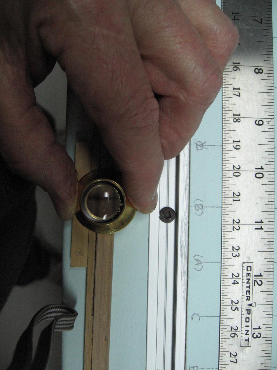
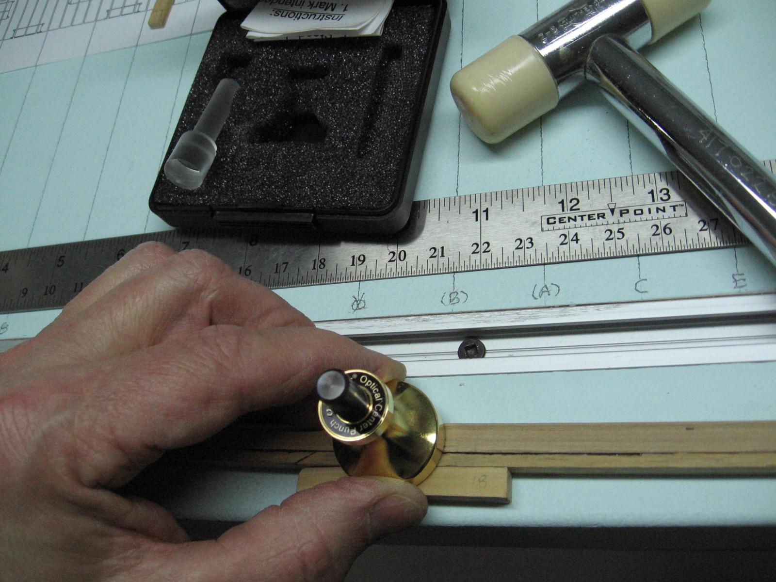
Sunday 27 March 2016 First opportunity to work on the model since last weekend. Let me start by saying how extremely happy I've been with last weekends work. I made a new scraper and threw that one out. Filing the cutting edge was a problem for me. Devised a new method using my dremel and a cutting wheel. This worked much better. Cut the rabbet on one side of the keel. As everything has been going too well I kept double checking because I knew this was all going too well. Was I cutting the wrong side? Nope! So far so good. Cut the rabbet on the other side... was I doing this one wrong? Nope! How did I manage that? Glued the false keel to the keel... did I glue it to the top instead of the bottom? Nope? Did I put it on backwards? Was it the right section? No and Yes... still going well. Marked the bolt hole locations in the keel scarph joints. Made a paper template and used my scratch awl to dimple the marks through... looked awful. Filled that in with wood glue and sawdust and tried again with a pin. Still awful. Made a metal template and tried again. Still awful. I have a centering tool but hadn't used it as the punch is pretty large. Possibly if tapped lightly it would be okay, it worked. Insert the magnifying cross hair piece to line it up to the mark, remove that and insert the punch and give it a wee little love tap.... repeat... they look great. Alignment is perfect. Marked all these bolt hole locations. I knew all was going to well. The keel that was straight all week is now warped!!!! Lifted up almost 3/8" (1cm). How did this happen? Any ideas what I should do now? I cannot soak it as the false keel will unglue. I've presently have it set up with weights and am attempting to counter bend it. Any ideas?


-
These are the frames and their width dimension fore and aft (as opposed to the molded dimension ... inwards or athwartships) is determined by the room and space specification for that particular frame station. It can be different along the length of the ship. Look at how smart I seem ... don't be fooled ... I just learnt this a while ago.
-
I think the "bubbles" are the tiny pockets in the grain of the wood. You have to use a less powerful camera to not expose this