HOLIDAY DONATION DRIVE - SUPPORT MSW - DO YOUR PART TO KEEP THIS GREAT FORUM GOING! (89 donations so far out of 49,000 members - C'mon guys!)
×


AON
-
Posts
2,867 -
Joined
-
Last visited
Content Type
Profiles
Forums
Gallery
Events
Everything posted by AON
-
 Oh crap! Let you know how it works out
 -
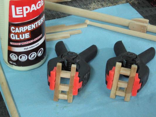
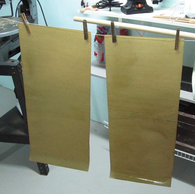
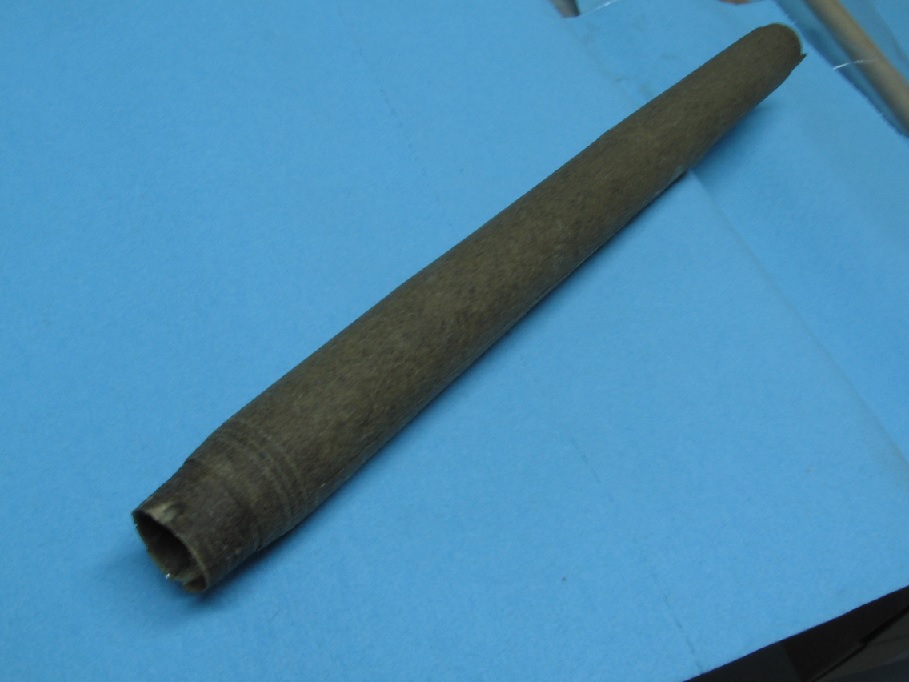
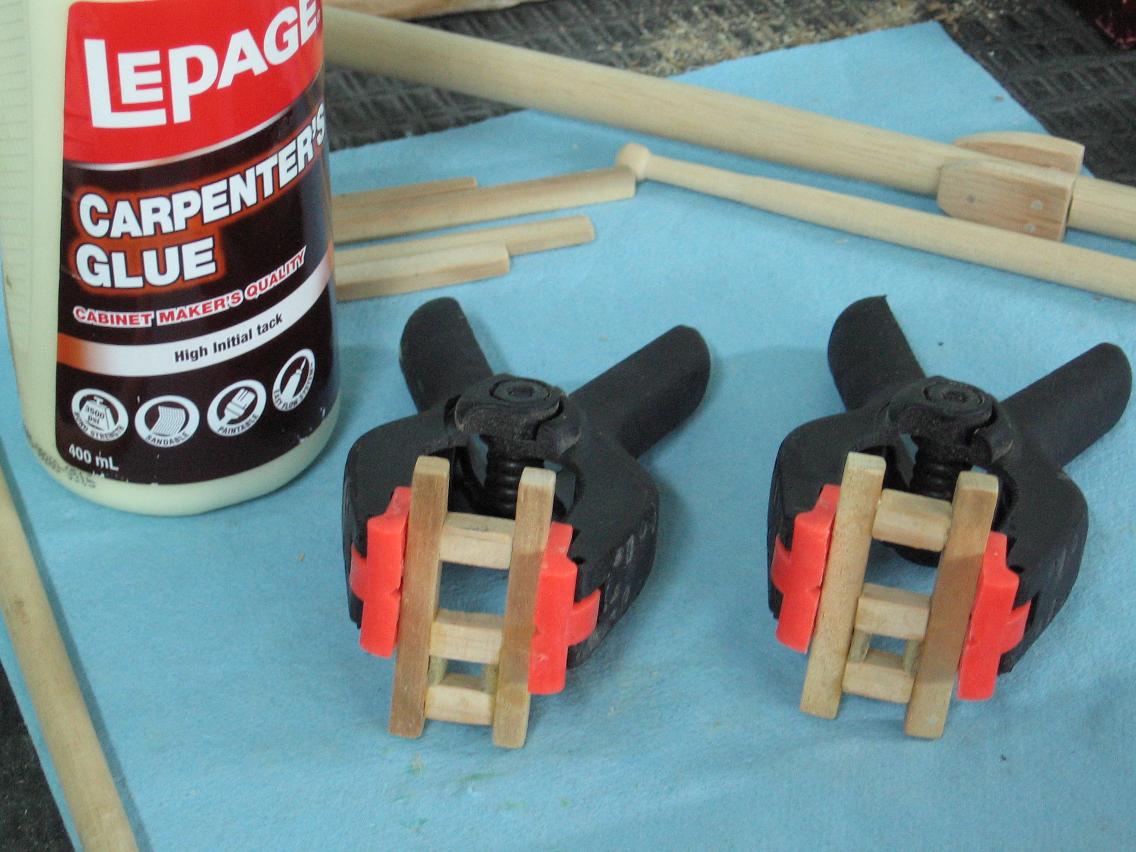
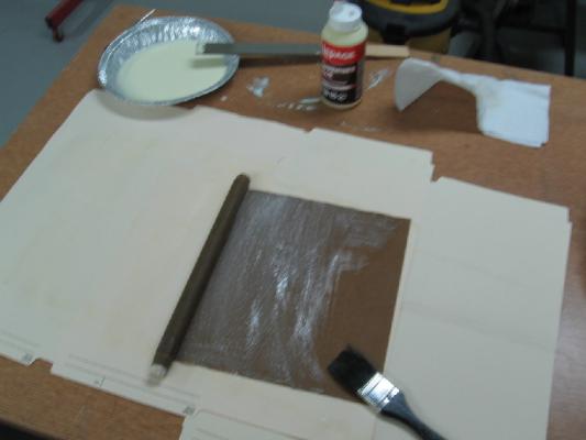
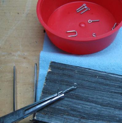
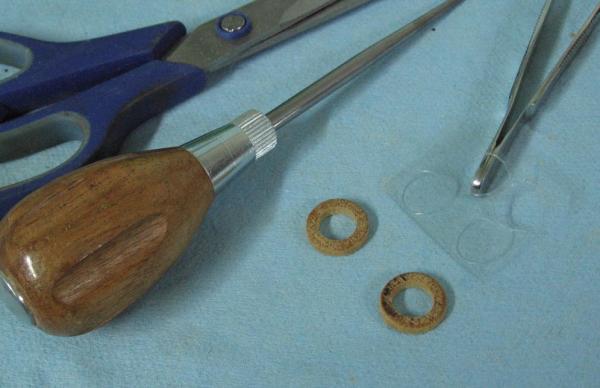
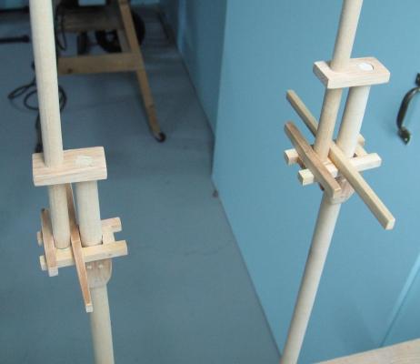
Tuesday 9 December 2014 Stained glued and rolled my newsprint to make the mast hoops As I had no wax I wrapped my dowel with plastic wrap The stain went on nicely, hung it to dry. I water my wood glue down and brushed it onto the paper It all rolled nicely when I practised before staining and gluing Not so easily to keep it all aligned when glued.. but it is done I should have removed it from the dowel late last night but hadn't done it until early this morning (Wednesday) It had not dried through as yet but was making considerable progress about a half hour later since the dowel was out! Should be well cured by the time I get home from work tonight. I also made up the remainder of my eyelets Singles, doubles and 16 combination Long/Short doubles I hope my count was right.


-
BZ !! She looks fan-freak'n-tastic
-
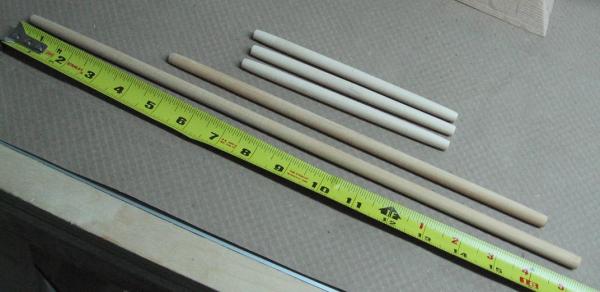
I have a length of 5/8" dowelling to use as the bar (mold) to wrap around. Might be using a light coating of petroleum jelly in lieu of wax. I also have some clean newsprint paper (no ink on it) I will try this technique tonight. I like the look of a dark stain against the mast so I think I will try brushing a test piece of paper with stain. If this doesn't work I will use the black marker. Wish me luck.... and thank you once again Dee Dee and Druxey for the alternate mast hoop making suggestion.
-
I must be the odd one as I liked the contrast but what I liked isn't important. It is still very clean, sharp and damn beautiful to look at.
-
Thank you Dee Dee I like the "stationary" fabricated hoop and not just because I'm a cheap old bugger that can't waste a dollar... actually we haven't got $1 bills in Canada anymore (ours is a coin called the Loonie because of the Loon image) I am going to check out your link as this may be the kitty's derriere of a method! Alan
-
Interesting method I imagine the wax keeps the "molded" glued wood shavings from sticking to it so it can be removed from the cast shape. Finding a rod of the right diameter... like dowelling. I liked the "look" of the results of my slightly oversized piece and want to see if I can manage as the melamine stains nice and dark for contrast with the mast ..... but this looks like my plan B. Thank you
-
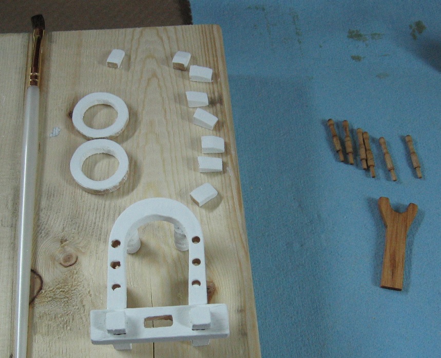
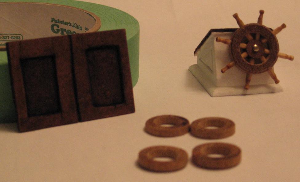
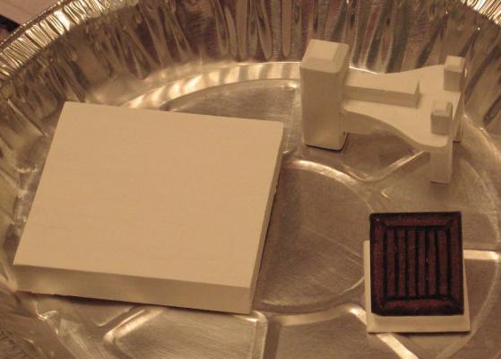
Thank you everyone for the likes Painting and staining some bits. Not quite done with the painting yet. The rings and little blocks are the mast shelf ring s that the sail hoops will rest on. I made 1 of 28 mast hoops for the sails (not in the photo below) I used two hole saws, one inside the other (5/8" and 1") to cut the hoop out of 1/8" melamine. It looks good by itself but when on the mast seems too large a diameter and too sloppy a fit. I'll have to try a 1/2" drill bit in a 3/4" or 7/8" hole saw cutter. This may end up being a two step operation which will then be very tricky to keep the holes centered to each other.

-
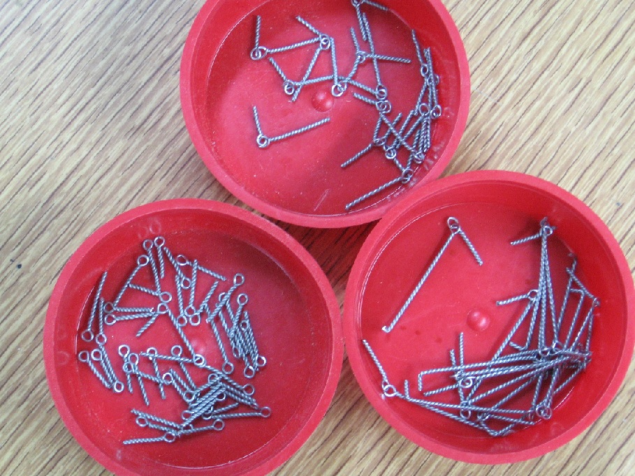
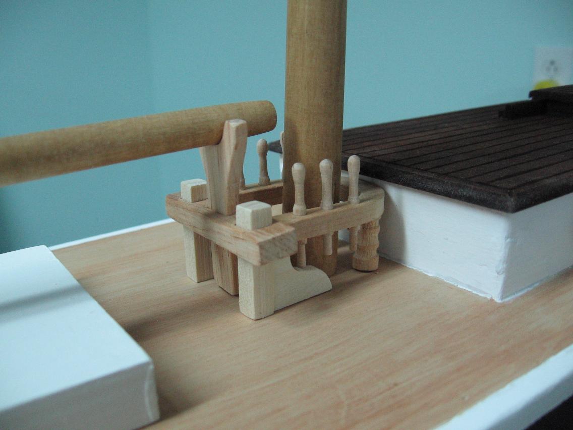
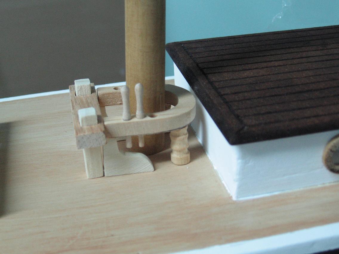
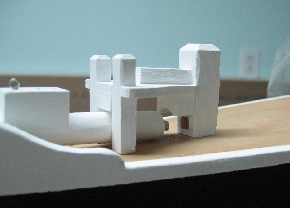
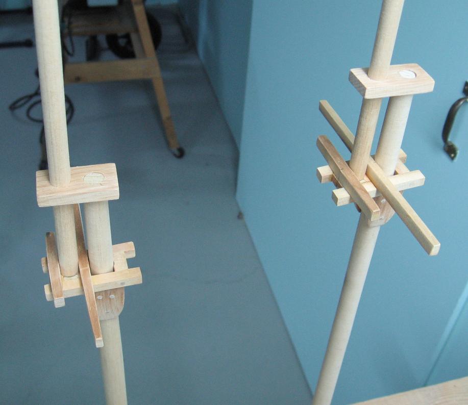
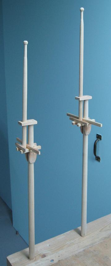
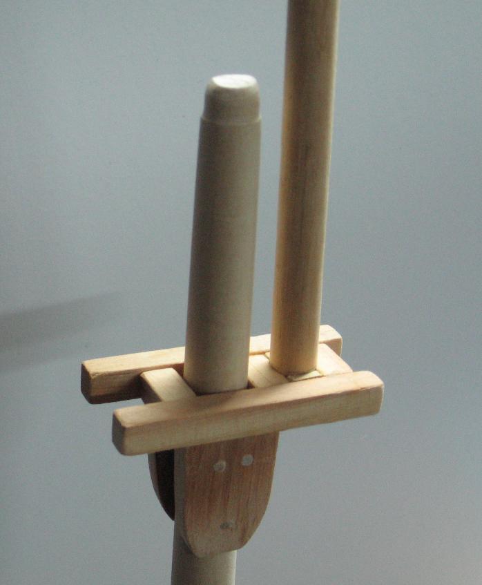
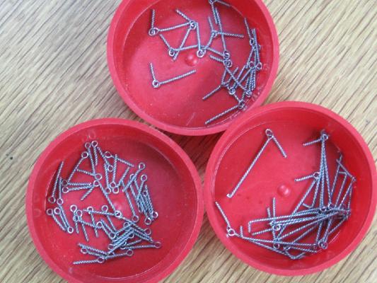
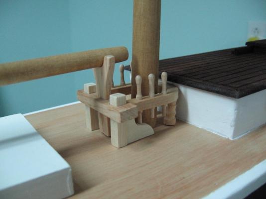
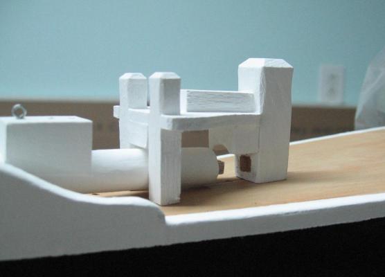
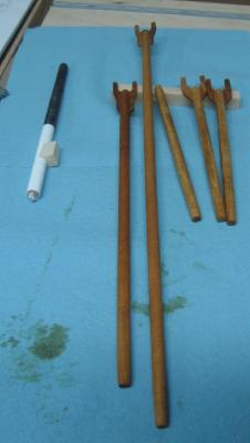
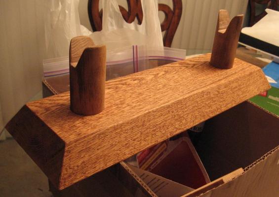
Completed the NEW fife rail and spaced the pins a wee bit. I think this version looks better ... also added the boom crutch The crutch and pins will be stained the remainder painted white Spent the afternoon twisting up 55 eyelets By my calculations I may need another 30+
-
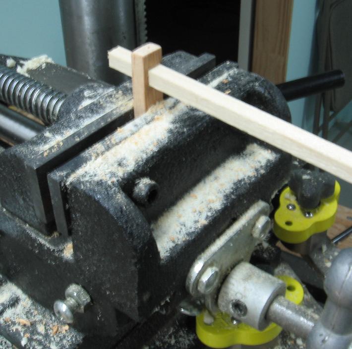
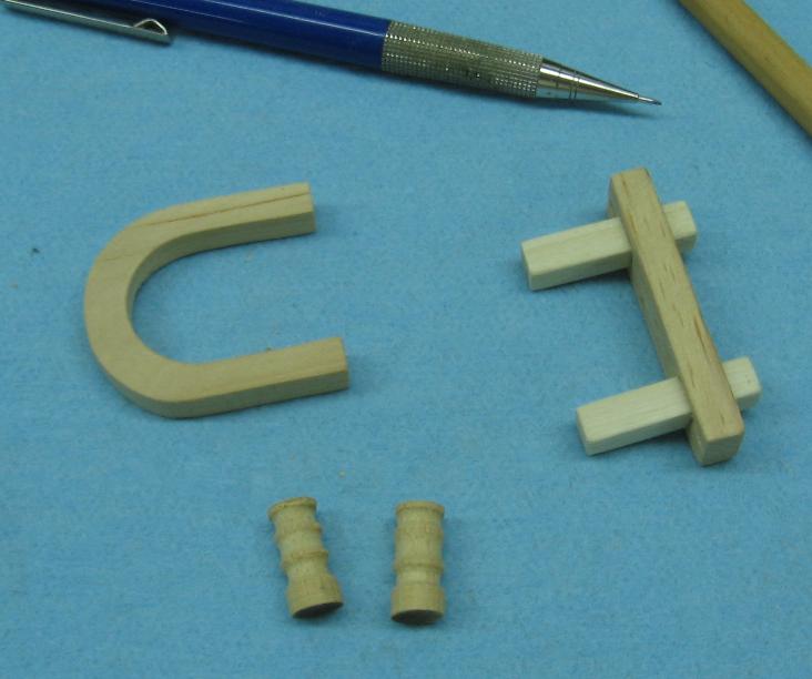
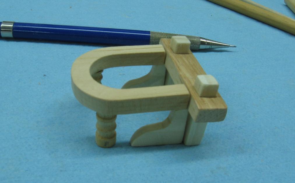
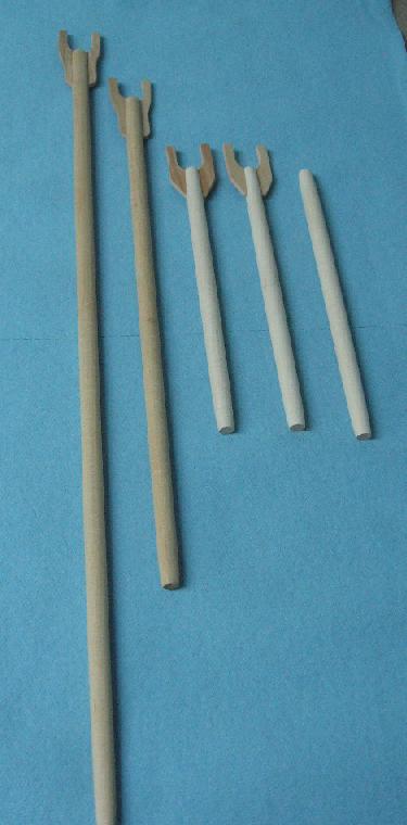
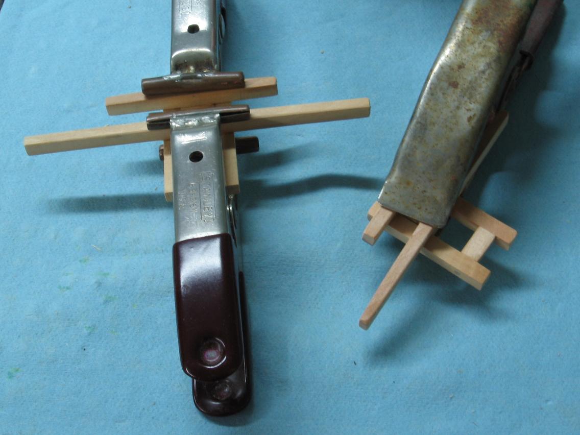
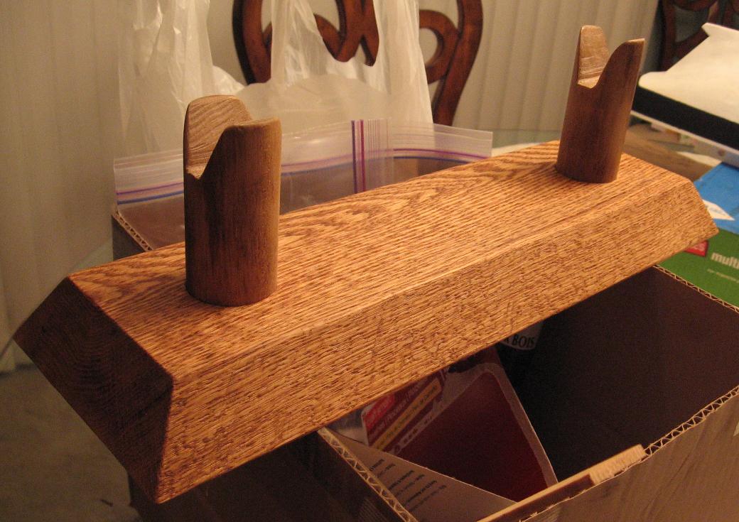
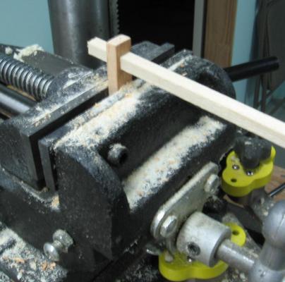
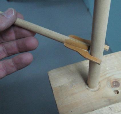
Part three Worked on the mainmast Fife Rail - made the end piece, drilled 1/4" holes for the square post and had to file the holes square to match - made the horse shoe shaped Fife Rail using hole saw, scroll saw and disc sander - made the support posts on my lath and the knee braces on my scroll saw - made two belaying pins on my drill press (used like a vertical lath) with files and sand paper Dry fit it all together The belaying pins seem too close together If I stretch the rail to space the pins more the scale of the rail seems like it will be too far off I am of a mind to leave it be (for now) and let it stew for a bit On the other hand it hurts nothing to make a second slightly longer rail just to see for sure! I have to finish the other pins and make the Boom Crutch


-
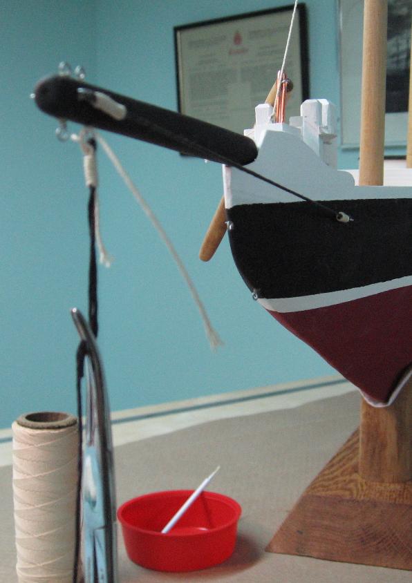
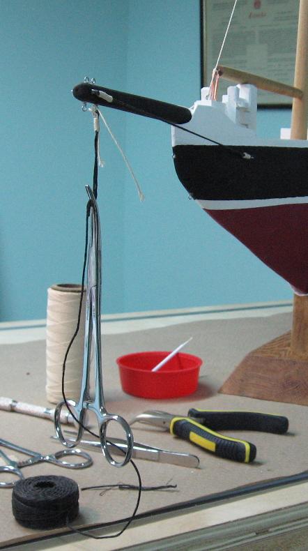
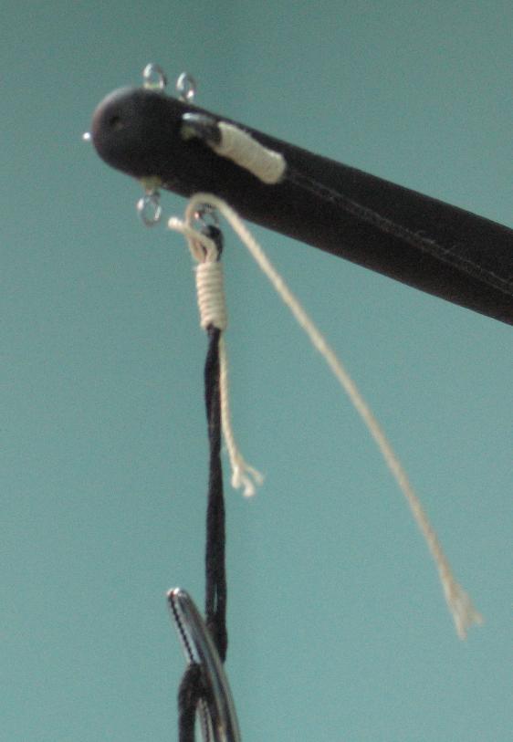
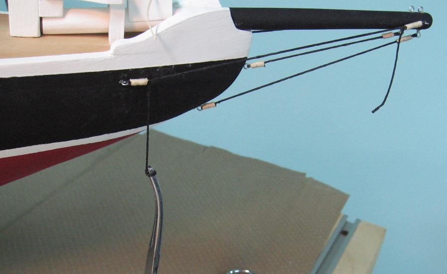
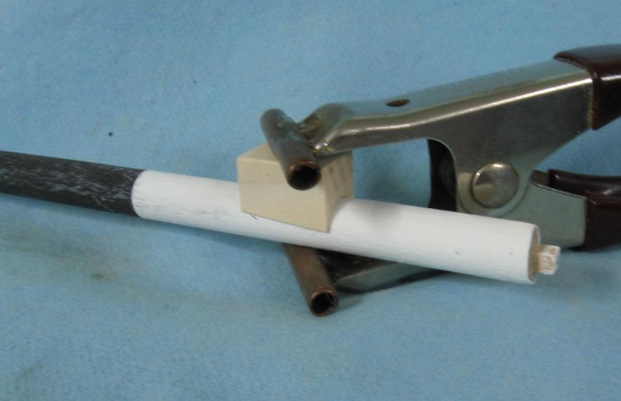
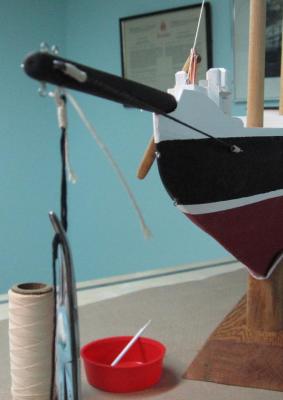
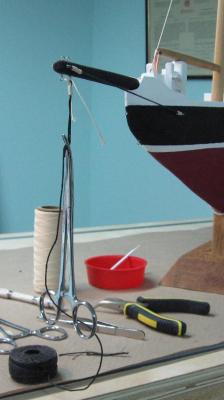
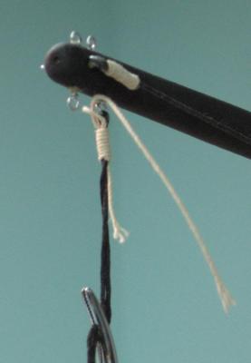
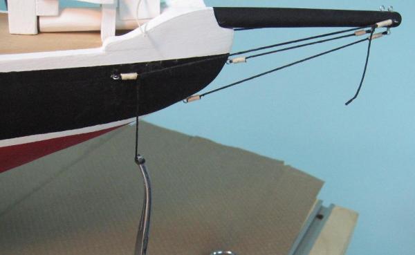
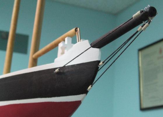
(Part 2) Started line work on the bowsprit Decided to use some of my sea cadet Boatswain and OJT boat shed skills and do some simple whipping I had always done whipping (in real life ... full scale) with waxed twine to finish the cut end of a line (rope) or a back splice could be made I used Black waxed line as my primary piece and tried black thread to do the whipping It disappeared to the eye so much so that I couldn't see the whipping at all I then tried white thread It seemed too small and the black came through highlighting the gaps I'd made In the end I used a thicker three strand 100% cotton twine (off white) and was happy with the contrast Whipping is done by 1. making a bend (fold over) the small stuff (twine) and hold it against the larger line 2. wrap the small stuff tightly round the large line working from the standing end and go towards the bend 3. pass the small stuff end through the eye of the bend that is left exposed 4. pulling on the standing end of the small stuff until the bend is drawn under the wrapping to hide it and secure it 5. trim off the two ends of the small stuff When I completed the other end I had an unavoidable sag in the line I pulled the end of the larger black line (holding the whipping close to the eyelet with my fingers) to draw it snug and taut. Then I trimmed the larger line and applied a dab of glue as my "belt an brace" for the assembly so it doesn't come loose somehow (it never did in real life but this is tiny work so I just don't know how it might hold up over time)

-
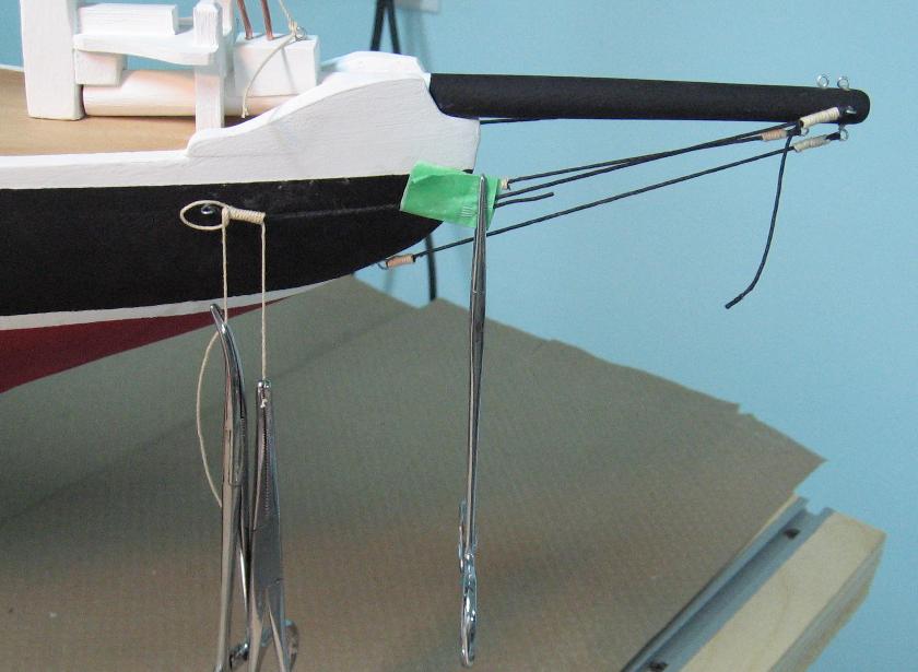
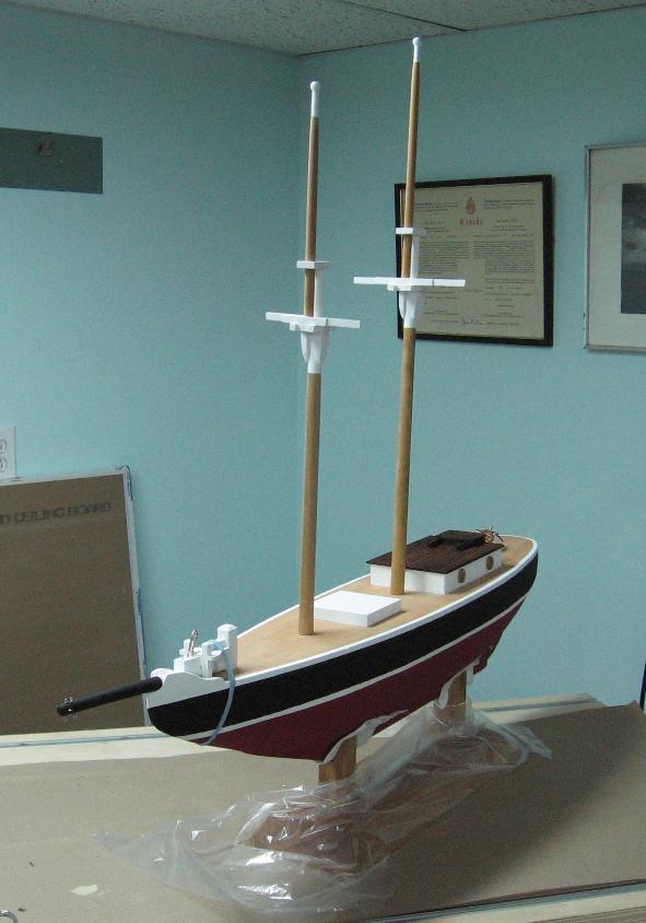
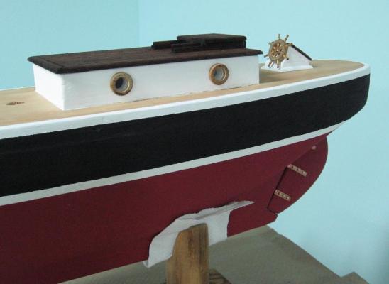
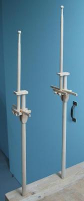
Saturday 6 December 2014 (Part 1) Worked on painting and assembling the masts and bowsprit Bowsprit and Samson Post assembled and glued in place Eyelets added to bow of hull in readiness to do some line work Mast assemblies installed to deck dry (not glued yet)


-
Thank you Michael It is all coming together in time for Christmas as promised. It is also a little sad as I have become attached to her. There is so much more I'd like to do (especially since I took the sail making seminar last month) but I have already done more than asked.... and I've blown the budget.... but knew I was going to be getting more then I was going to be giving when I started
-
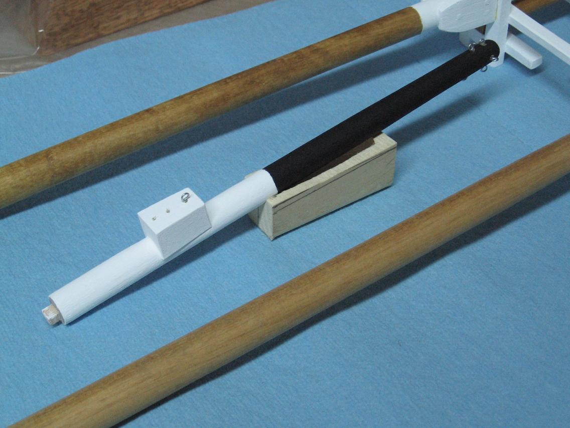
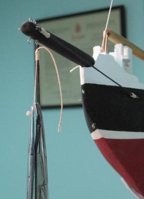
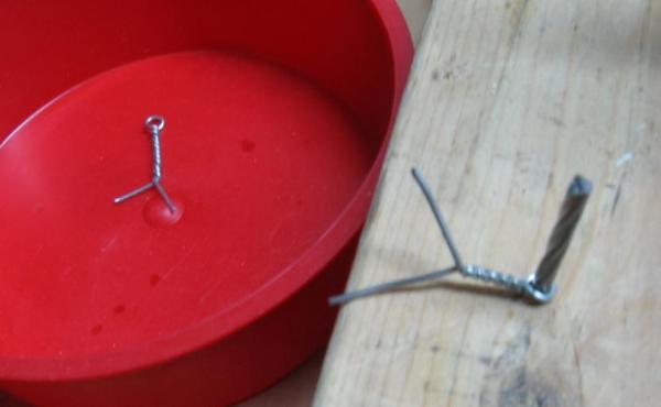
Friday 05 December 2014 Added block to bowsprit to attach jib boom and jib stay to - drilled out 7/16 diameter hole to match bowsprit diameter in location of assembly - cut through hole at 5° angle to match bowsprit assembly angle so top of block will be horizontal - sanded all sides to required thickness then sanded edges soft (removed sharp corners) - glued and clamped After all the fitting in place to get this right the bowsprit paint job was damaged so I will need to freshen this up. Started making tiny eyelets to tie off to - hammered finishing nail into my work bench to bend to - twisted 22 ga wire to the nail - cut the nail head off as I couldn't slip the eyelet off! - trimmed off end Stained the masts, booms and gaffs Will paint the unstained portions white


-
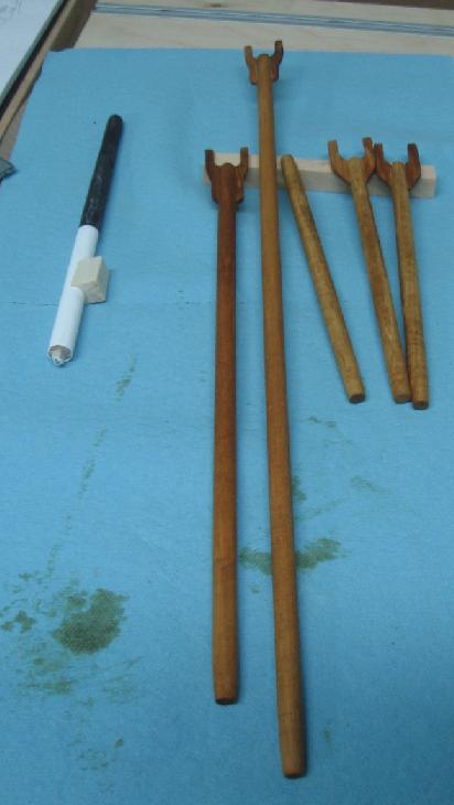
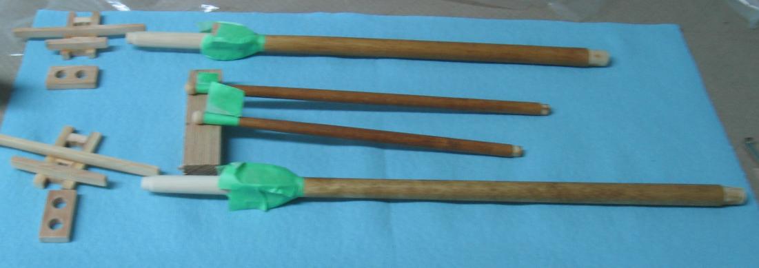
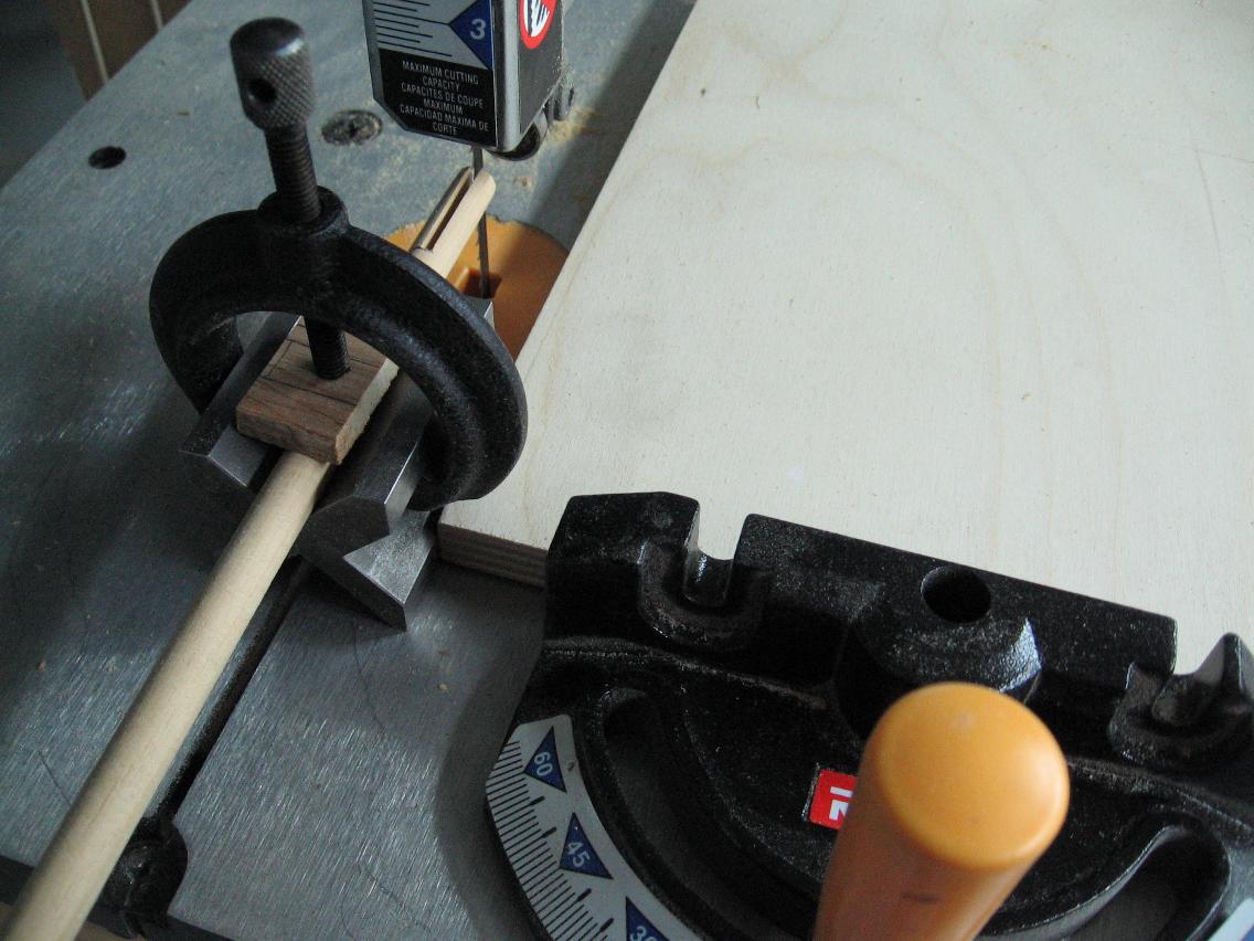
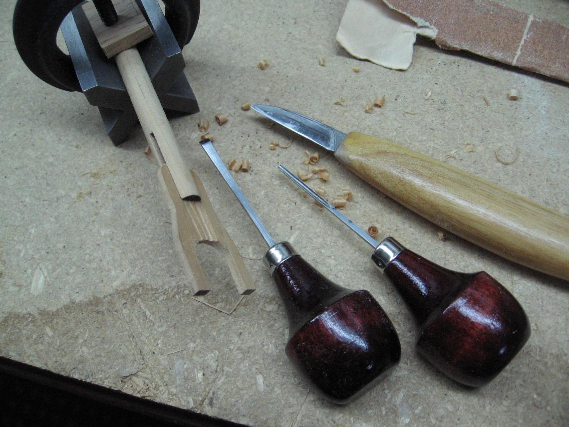
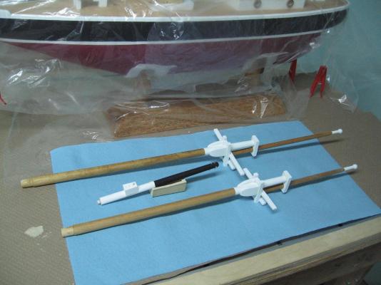
Thursday 04 December 2014 Worked on Booms, Gaffs and their Jaws I chose to make each jaw in one piece - cut a slot in the end of the boom or gaff - chiseled steps in the jaws to fit - chiseled channels in the steps to hold glue Worked on the Port Hole assemblies - scribed the window cut lines into plastic sheet - cut out the glass pieces - dabs of glue in bulkhead port hole recesses to hold the glass in place - glued the port hole rings over top Assembled the Rudder and attached (glued) bits and pieces to the aft end I used small store bought brass nails on the rudder I had to cut these considerably shorter and file a new point to them


-
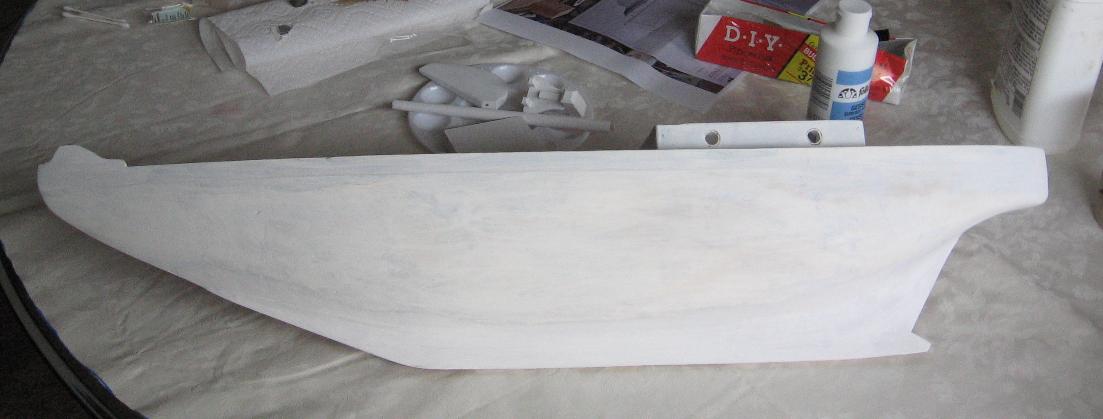
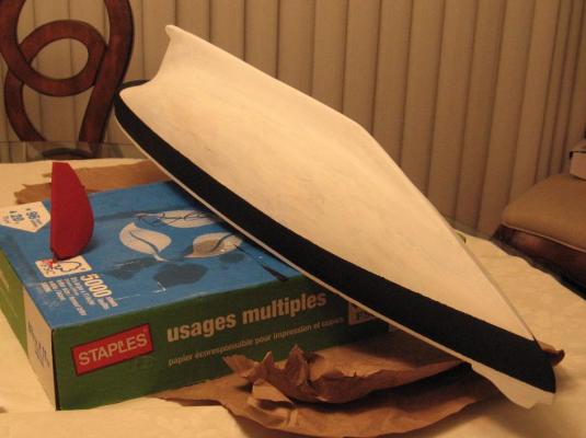
Tuesday 02 December 2014 Completed the painting of the underside of the hull red Need to do touch ups to the white and black to be completed this stage Completed the assembly of the cross trees and trestle trees to the masts Dry fitted all together Started working on the main boom again

-
Good morning Tadeusz I have this same item as I thought it would save me some time... I rarely use it and if I did I'd still go back to wet stones to finish off the best edge ever and (as the other fellow mentioned and I forgot to) a few wipes against the leather strop to boot. A really good edge makes your work much easier and almost look masterful... especially when your not a master. Alan
-
very nicely done!
-
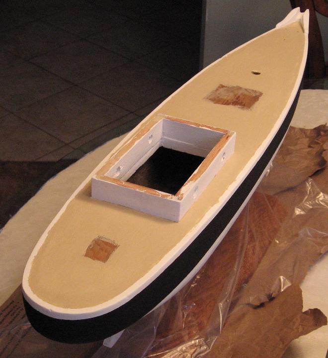
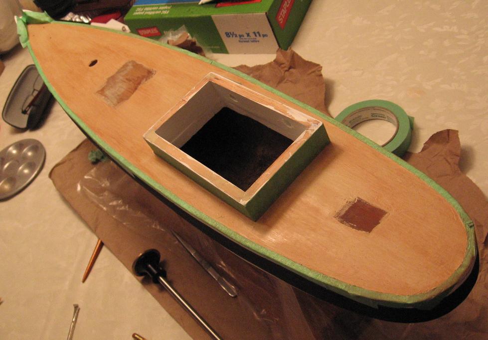
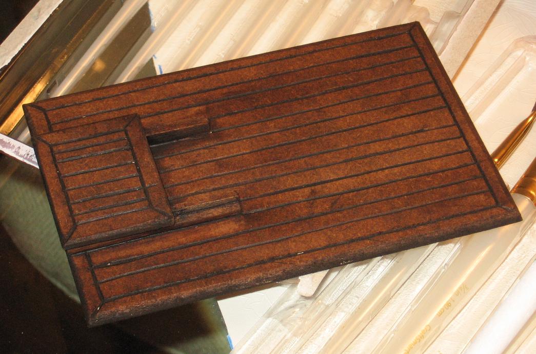
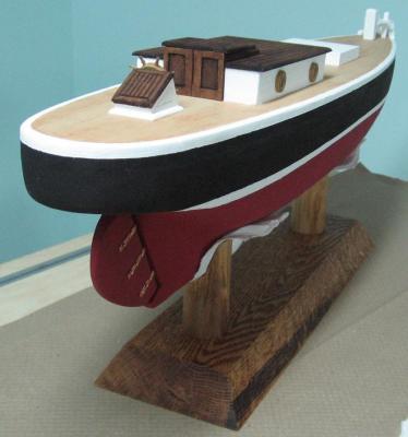
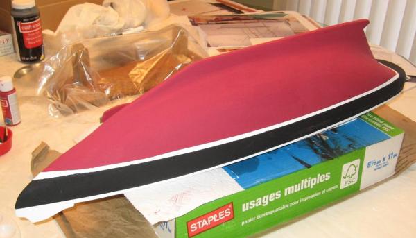
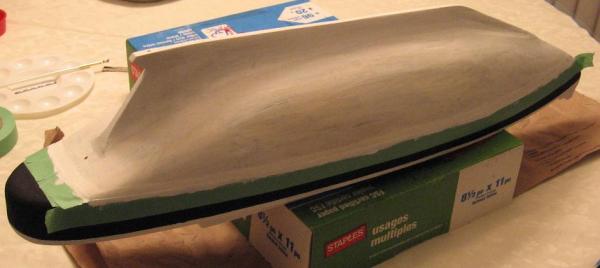
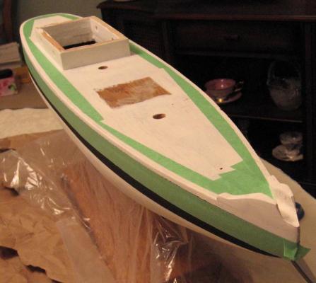
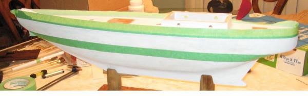
Thank you Druxey The black band seems a bit narrow to me but I cannot go any lower or I'll encroach on the rudder elevation Sunday 30 November 2014 Continued with painting - lower white band on hull - upper white band on hull and deck - one coat of unbleached (undiluted) white on deck - one very light coat of watered down Autumn Brown (ceramic paint from my darling wife's stash... with permission and tutoring!!!) applied with a fanned brush drawn long along the deck to simulate wood grain (my wife knows a thing or two about painting). That deck turned out better than I ever imagined. Why faux wood grain and not an application of thin planking? "BUDGET" That is why I am using most of my scrap wood on this project. In the end it will be 1000 X more then he ever expected (and I hope to catch that expression in a photograph) I was originally thinking of drawing in lines to simulate the planks but I'll likely screw it all up and I think this is one of those times a person needs to know when to say enough. Next is to paint the red bottom, touch up the white, attach some of the bits and pieces and get back to the booms and gaffs


-
I would use this type item on a new dull blade or edge to get it started I always finish with wet stones Once you have established an edge it is easy to keep it extremely sharp with wet stones If it gets a bad ding in it I might go back to the grinder to start again
-
Saturday 29 November 2014 Painting and staining today (and tomorrow) Also a pic of the booms and gaffs... they need more work yet. I am very happy with the staining and hope the painting ends up looking as good I also started assembling the build photos in some chronological order to bind together to go with Charlie when she is done. I think they will all (father-in-law, daughter and son-in law) enjoy seeing all that went into her. I am going to be spending some time figuring out the standing and running rigging. If anyone has a cheat sheet they would like to share I am quite receptive to the idea! (hint, hint)


-
You are going to wonder how you survived without it!
- 968 replies
-
- 1
-

-
- hahn
- oliver cromwell
- (and 1 more)
-
one more thing I needed to know how to do smarter! Thank you
-
Thursday (evening) 27 November 2014 Completed assembly of the trestle trees - dry fit last block - marked location - glued and clamped will lightly sand tonight and make the two caps I also cleaned (vacuumed) off the hull which revealed a couple more minor dents that were filled And I determined the sizes (diameters and lengths) of the booms and gaffs (again by ratios) and cut my material Still plan to start painting this weekend!