HOLIDAY DONATION DRIVE - SUPPORT MSW - DO YOUR PART TO KEEP THIS GREAT FORUM GOING! (89 donations so far out of 49,000 members - C'mon guys!)
×


AON
-
Posts
2,868 -
Joined
-
Last visited
Content Type
Profiles
Forums
Gallery
Events
Everything posted by AON
-
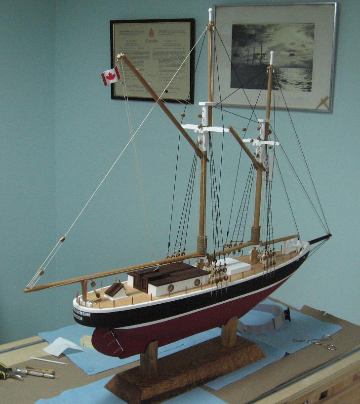
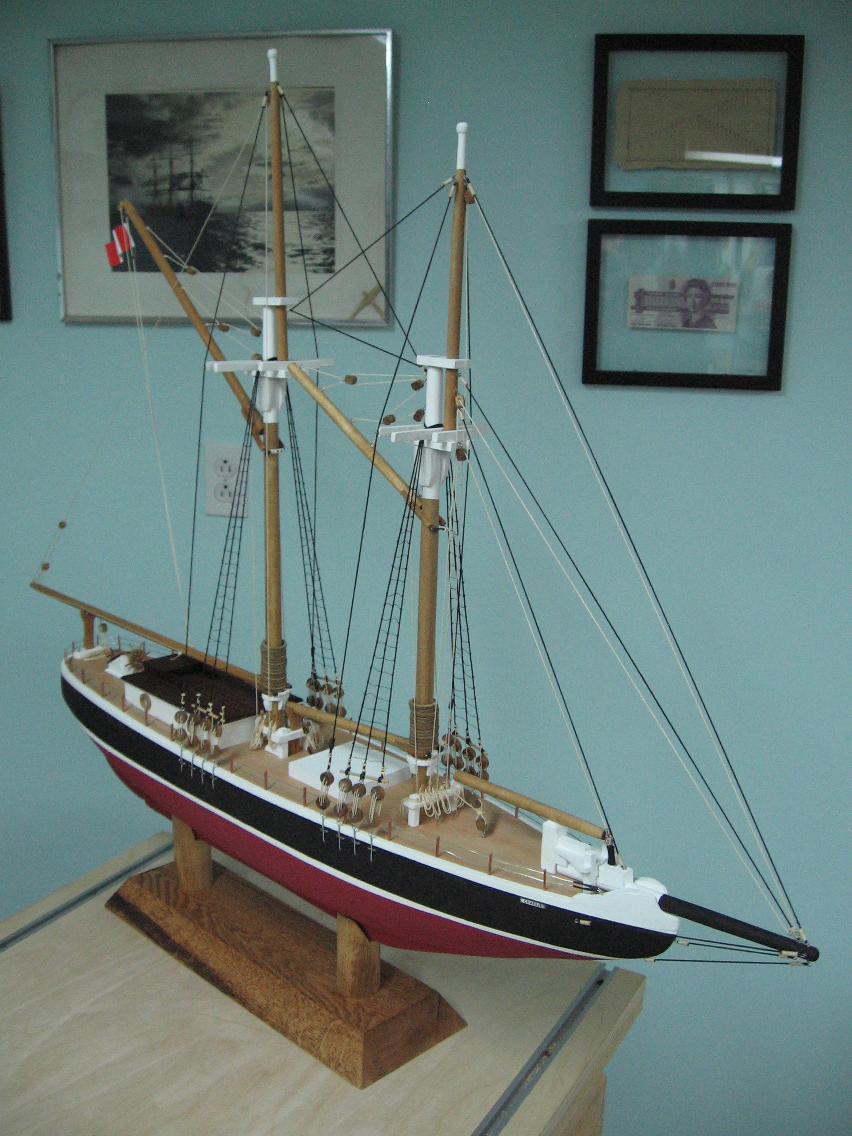
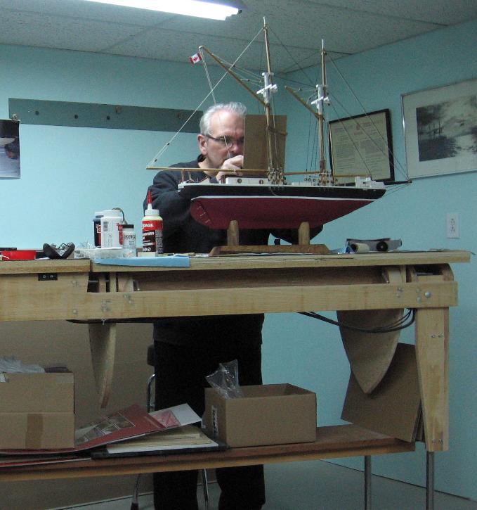
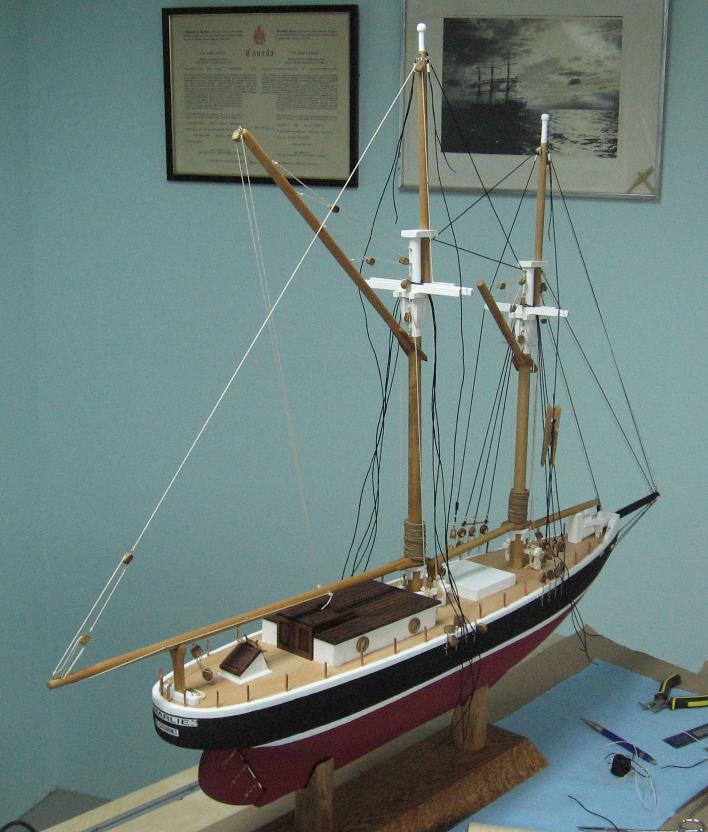
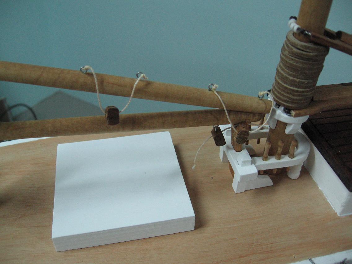
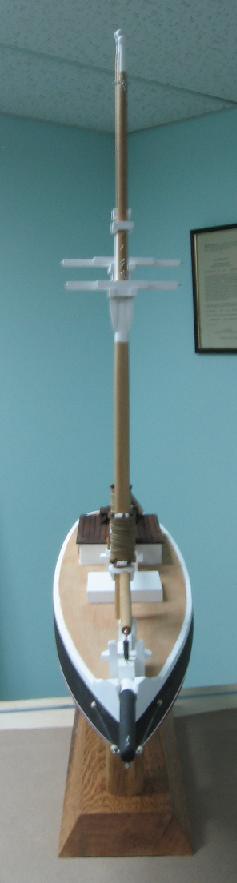
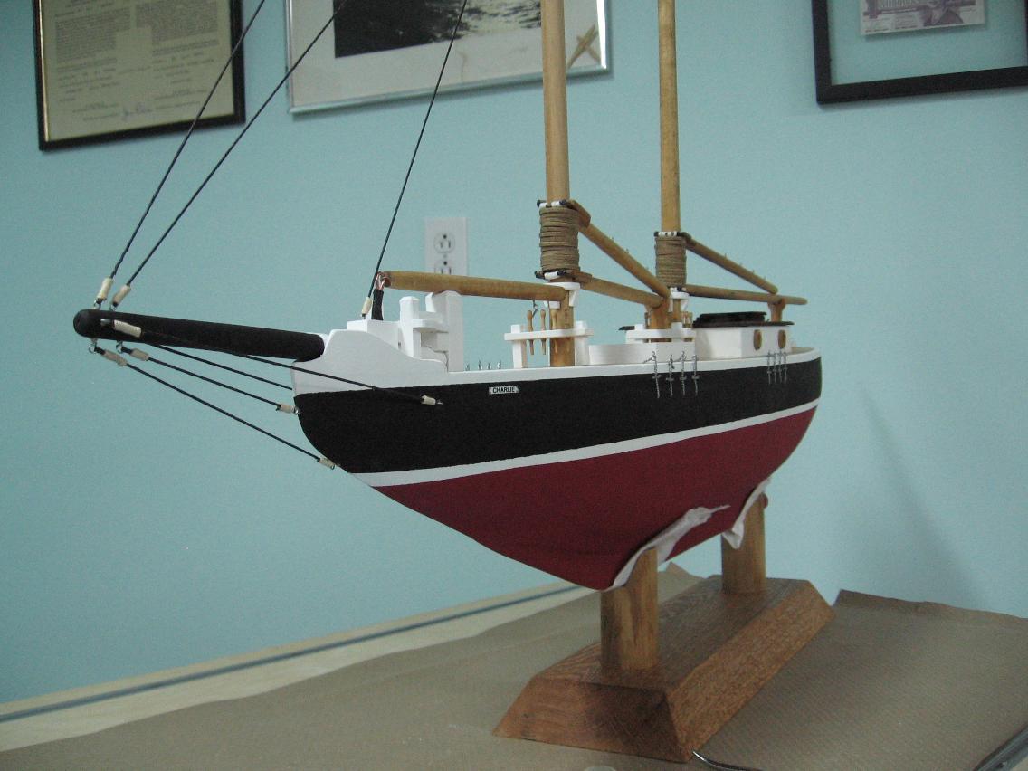
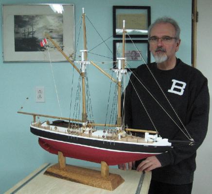
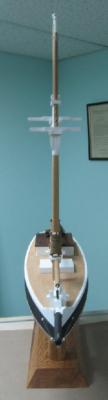
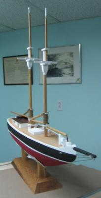
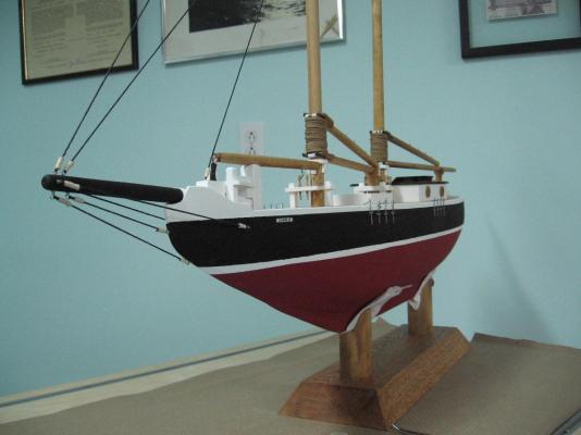
 Thank you "O"! It was more than I planned to do but I found I almost couldn't stop myself. As I said earlier I am sure I got more than I am giving. Hope to have some photos of tomorrow and I will post the PDF. She is mounted on a plate (3/4" plywood) and ready to transport. Alan
 -
Thank you. waiting for the son-in-laws reaction tomorrow!
-
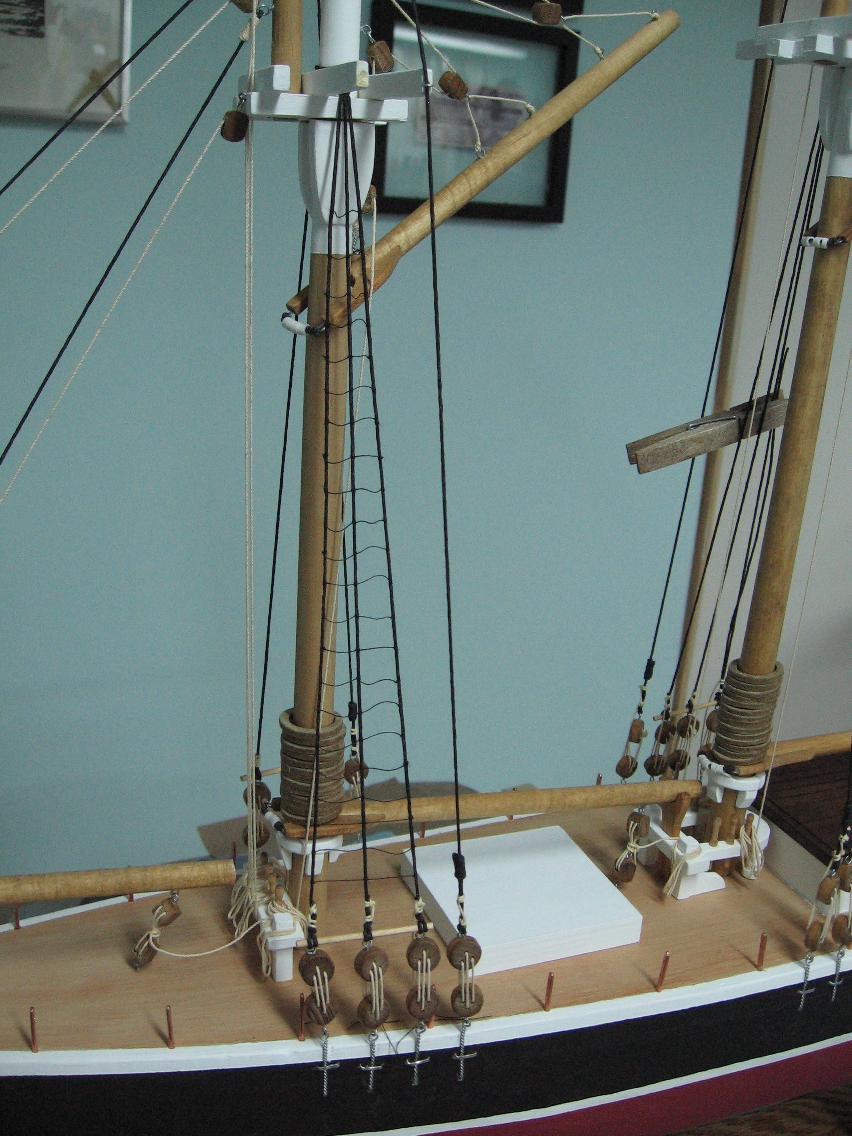
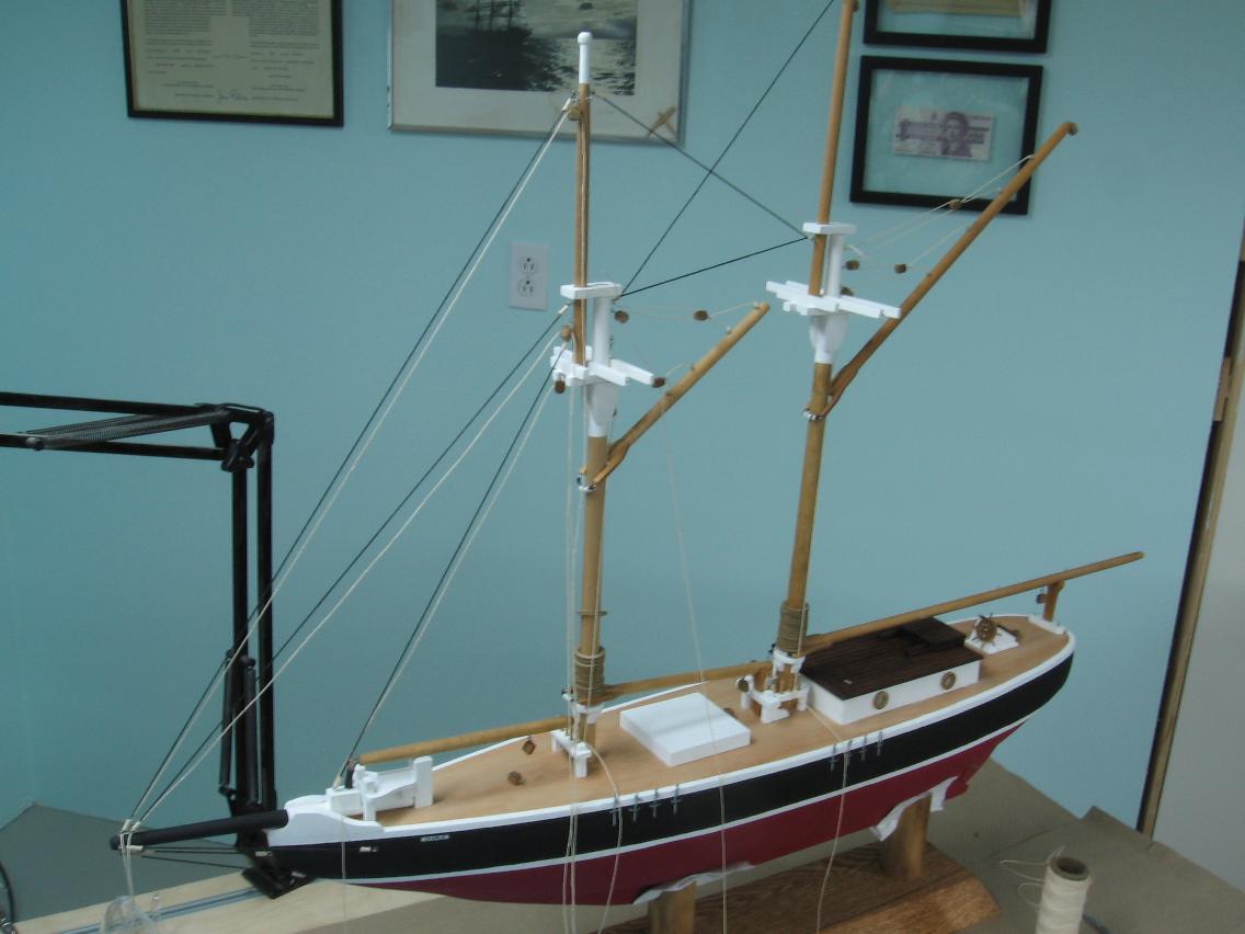
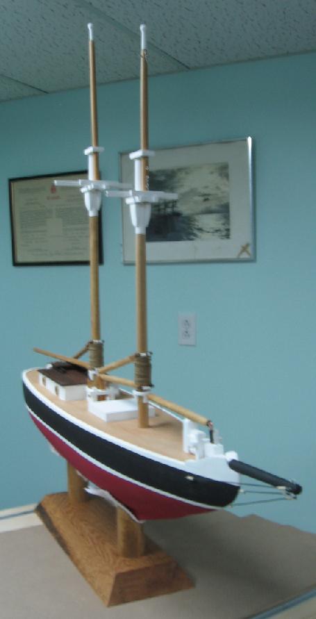
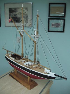
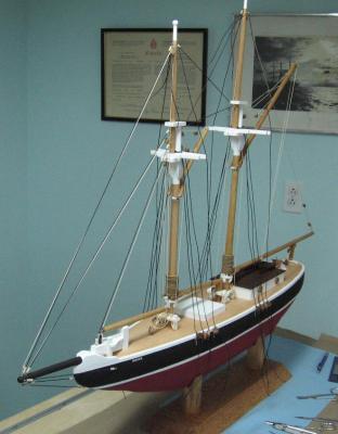
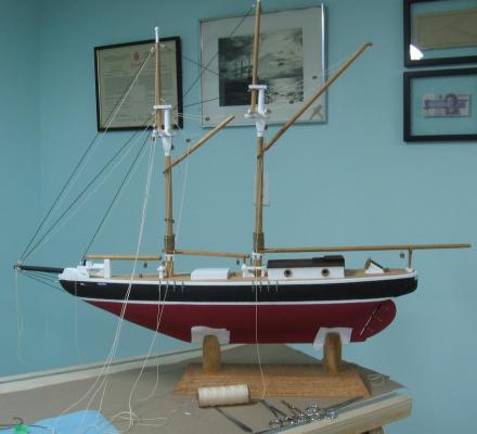
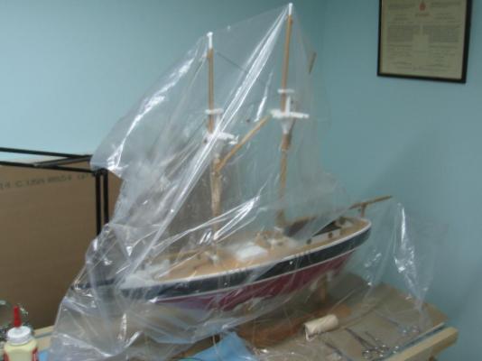
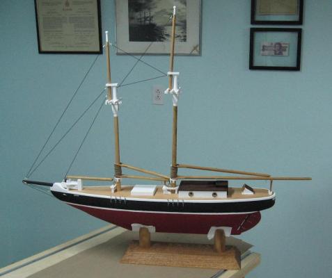
Monday 22 December 2014 (afternoon) I completed the port side main mast ratlines and started on the starboard side fore mast ratlines but my eyes kept wandering to the rear. It was there, my mind could see it but my eyes would not register it. After quite a few glances aft it popped out like a sore thumb. I had the main mast shrouds forward of the ratlines! Yes... both sides. (no sense doing a job half way) Cut the dead eye running lines off and corrected them all. I completed the ratlines and then installed the handrail wires (22 gauge bright steel wire from the florist section of the hobby shop) I finished them off with some black electrical wire heat shrink tubing Touched up some of the painting and (drum roll please)...... she is done! I will now complete the PDF collection of build photos to go with her so they can appreciate where she started from and how she got to where she is now. Delivery... 9 am tomorrow morning.


-
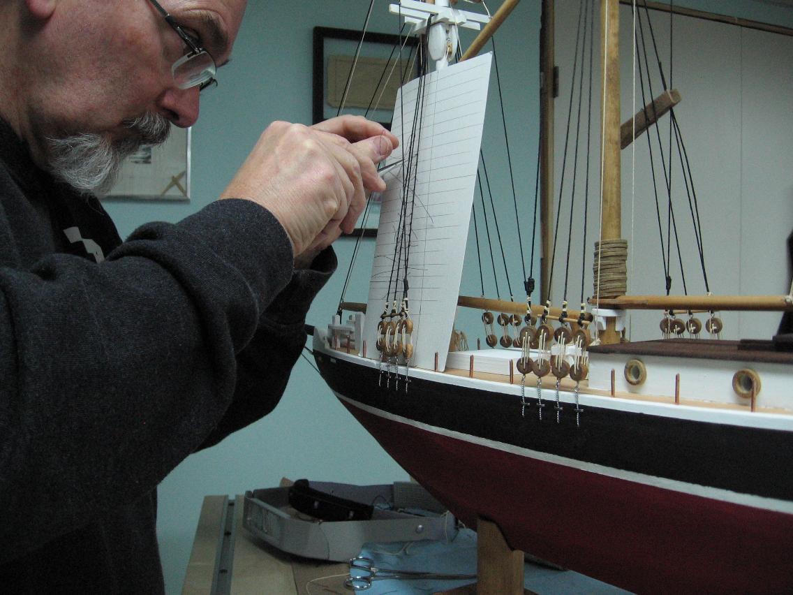
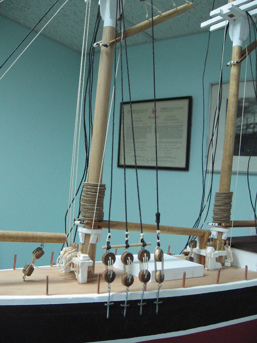
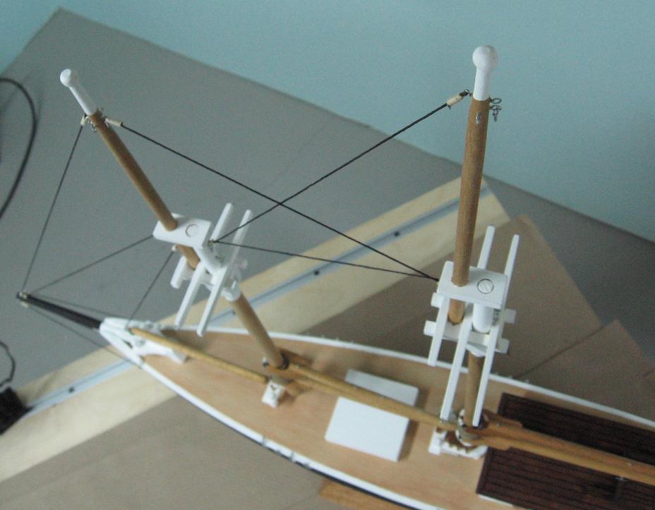
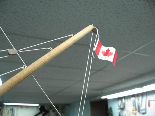
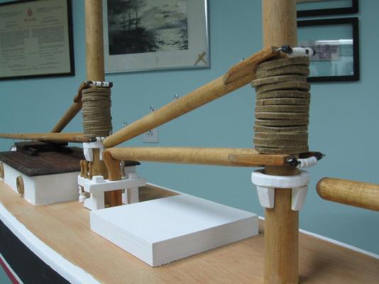
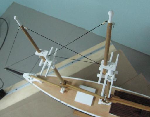
Sunday 21 December 2014 I attached the flag. Added two small ringlets to the halyard and secured the flag to them Completed the rigging of the deadeyes Had to re-do one from Saturday as it wasn't quite right Started on the ratlines My table got a workout during this phase (raising and lowering) and this made a huge impact on comfort. I used what I had that seemed correct for scale and was very concerned it would be too small a line ... but it looks very good to me. Managed to get the port side foremast ratlines completed and about 90% of the port side mainmast ratlines before I had to call it a day. I should be able to finish these today (Monday) and get the handrails installed to the stanchions ... and then I am done. Depending on the time it will be delivered today or tomorrow (Tuesday) morning.


-
tons and tons and tons from really long pipe clamps to tiny C-clamps, medium size spring clamps to cloths pins and somehow there is never enough
-
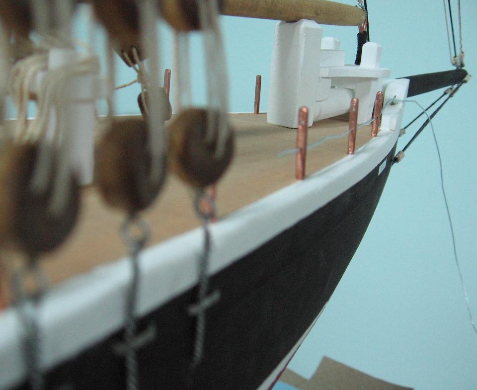
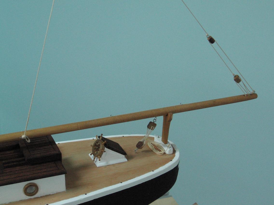
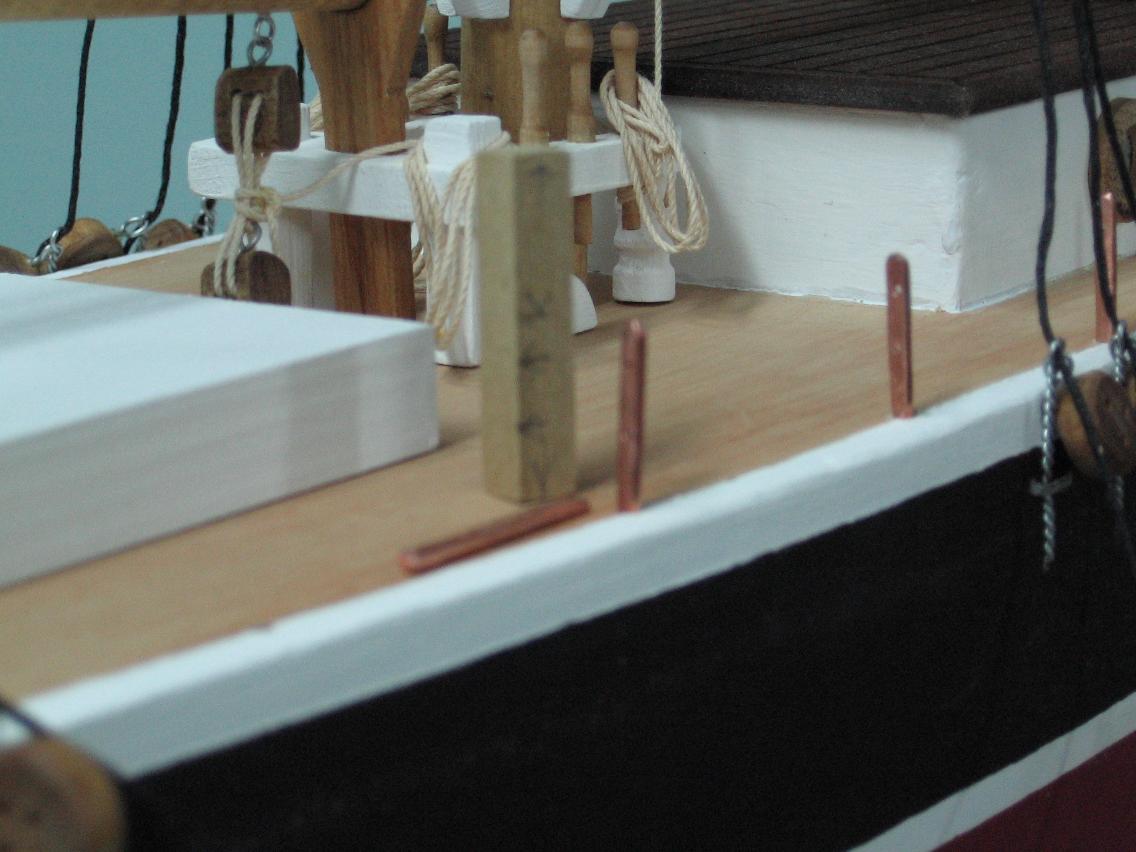
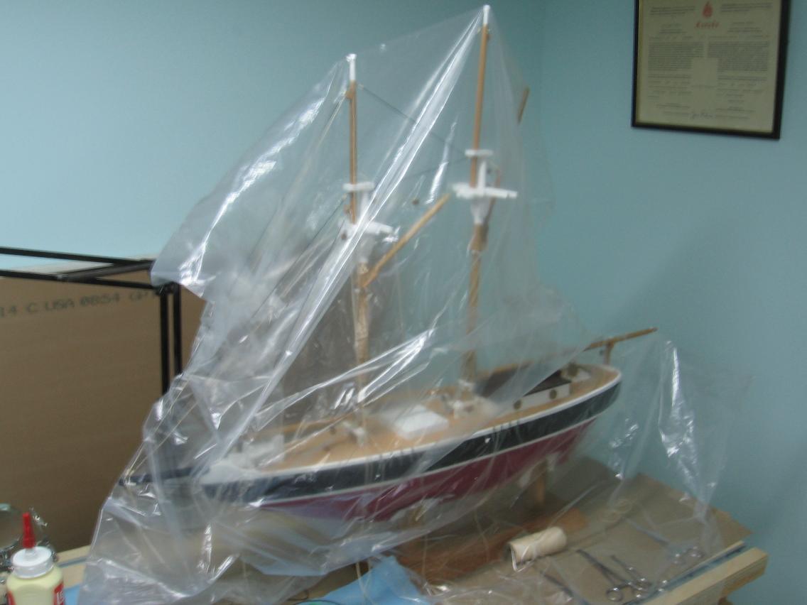
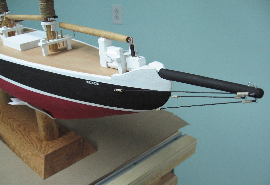
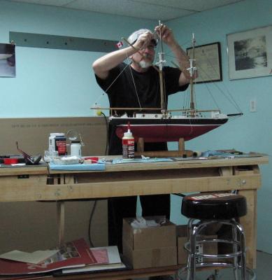
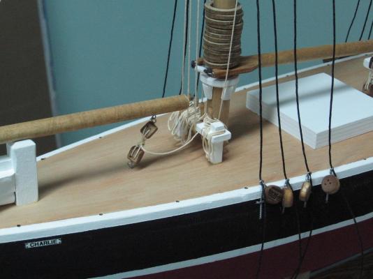
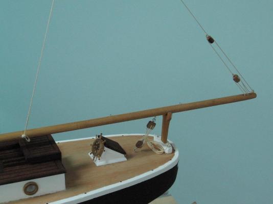
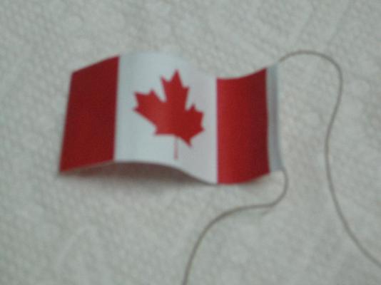
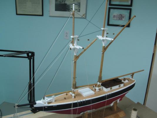
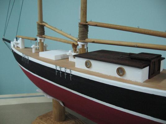
Saturday, 20 December 2014 Made the second flag which turned out slightly better (the first had a little ripple between layers on one side) Re-rigged the forward fife rail and did not get carried away with snugness (yes Druxey, everything worked out wonderfully!) Started on the standing rigging when it happened (oh yes, yet again) I was wearing my magnifying lens head gear and had it flipped up Leaned in to focus with my music glasses (12" to arms distance focus) and the headgear pushed on the rigging and she toppled off the cradle. No I did not have her secured permanently to the base. Thanks be to the Big Guy upstairs nothing was damaged! I pulled out a piece of 1/4" diameter dowel (actually measured 0.2400" - 0.2411" diameter) Drill a 15/64" (0.2344") in the aft base post and in the keel Cut grooves in the pin, glued and hammered it into the post Placed the model onto the base and tapped her home with the palm of my hand on the cabin roof She is berthed solid now. I measured out and drilled the holes for the handrail stanchions then I installed these as I wouldn't have the room once the standing rigging was secured to the deck I used a small block of wood, marked off with the top of handrail and two holes as a gauge to assure all stanchions were all the same height. The top of stanchion and lower holes were not my primary gauge, the top hand wire hole was used for alignment. The holes drilled into the deck (at 1-3/4" spacing until I got to the rounded stern) are smaller than the copper wire is round so they are essentially dry nailed into place. I used every stanchion I made, no spares left over (and I planned for two). The reason was that the rounded aft wouldn't work at the planned spacing. I needed to tighten it up which caused the extra posts to be used up. Then I worked on rigging the deadeyes. Started the first one wrong (stopper Knot in the bottom) and had to start it over (stopper Knot in the top) I used an unconventional figure eight stopper knot as I was concerned it might pull through. I wrapped (turned the end through the bite) the line three times to increase the knot size. Finished one set. Prepared the second set, then called it a day. I am hoping to finish today (Sunday), but tomorrow (Monday) will be okay as he will still have it for Christmas. For my second ever model she is looking damn good if I do say so. Not masterful, but I am proud of what I've accomplished.


-
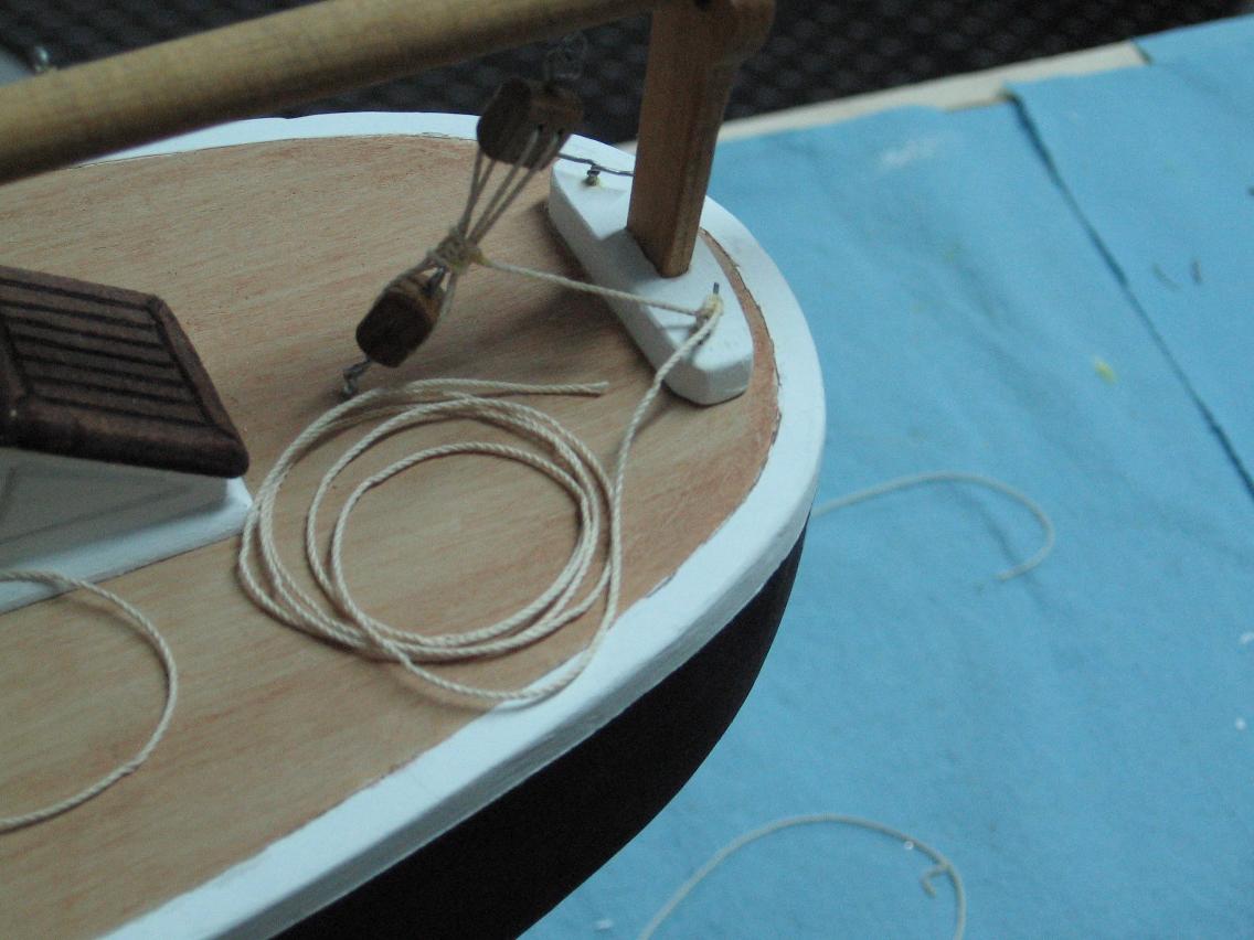
Friday 19 December 2014 (evening) I made such great progress last night... got my flag done (with rope) waving in the breeze It is two colour prints cut out and pasted with clear matte and curled to dry I have another print set that I will do a second flag and intend to use the better of the two I made tiny hooks and added them to the the sail and gaff halyards I tied off my third and last boom block and tackle set I then worked on all the lines up forward, tying them off to the forward fife rail, coiling them up and hanging them proper, damn it was looking good... and then it happened. The fife rail snapped clean off the deck! I undid all the work, cleaned off the deck and underside of the fife rail posts, drilled, pinned and re-glued it down. I certainly hope the second time will look as good... and I must not think of these as real lines, they must not be too taut.
-
mini drill chuck for those small drill bits
AON replied to AON's topic in Modeling tools and Workshop Equipment
I had in fact tried that quite some time ago but discovered the assembly was not symmetrical, the bit wobbled. That is why in my mind I thought you meant just the insert. My pin vice is the one in the PDF below. I also borrowed a different style from work to try and it too was not symmetrical. I'm guessing you've got a good one! PIN VISE.pdf -
mini drill chuck for those small drill bits
AON replied to AON's topic in Modeling tools and Workshop Equipment
Well I gave it a try and it did not work The Insert from the pin vice has three jaws The chuck on my drill press has three jaws but obviously larger The drill press jaw spacing does not allow the pin vice jaws to clamp or collapse, they bind up, so the drill bit does not clamp in place to allow it to be used. I tried spinning it a bit to see if it was just a misalignment thing, but it was not to be. I will need to purchase something and think I will get the two from McMaster-Carr to cover my bases This will be after the holidays as after today I am off for two weeks...hurray!! -
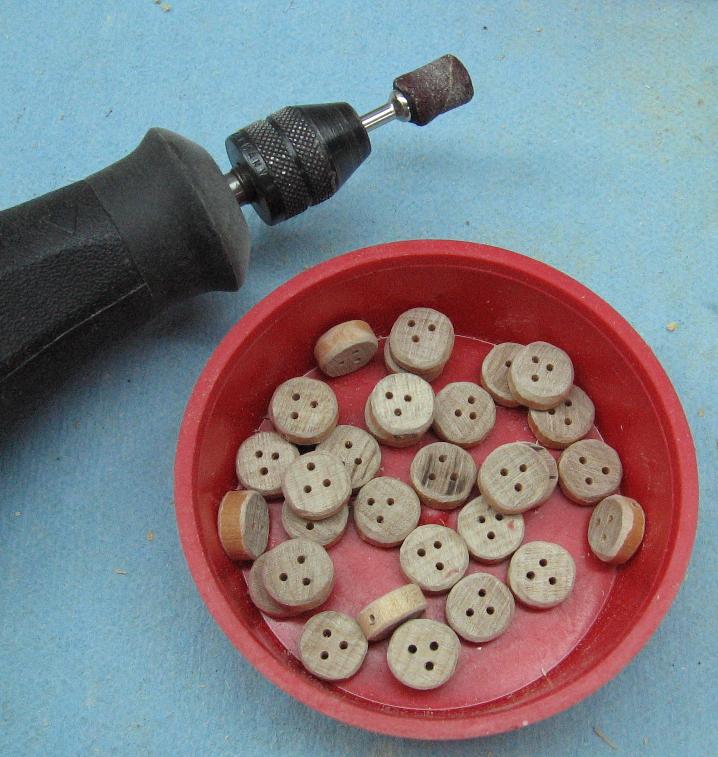
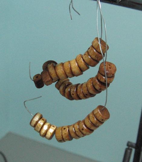
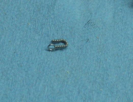
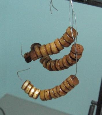
Thursday 18 December 2014 Sanded the dead eyes using my dremel to save my fingers ... then I sanded the skin off my thumb! Stained them and hung them to dry Friday 19 December 2014 (early morning) Attached the deadeyes to the eyelets (standing and running ends) I need to have a talk with quality control as three deadeyes did not have the holes in them for the eyelets I also secured the main boom (reeving the line through the blocks, tieing off with two half hitches and then securing to the cleat)


-
working on the yards had better be your plan "B" family first take the holiday off (if you can tear yourself away) you will thank yourself later (we can wait) and your family will be forever greatful
-
mini drill chuck for those small drill bits
AON replied to AON's topic in Modeling tools and Workshop Equipment
I have (what I consider) some $$ invested in a XYZ vice and a drill press combo. Not what some might consider major dollars but enough for me. I will try the "chuck" transfer from the pin vise to the drill press tonight If this does not "do it' for me I think I will just purchase the items from McMaster-Carr and be done with it. (If I order with our next shop order at work I save on the shipping into Canada) I will let you all know how it turns out Anything is better then doing it by eye and hand which is what I've just gone through ( you get older [eyes] and less steady [hands] ) Don't get me wrong, I love my dremel but the drill press is sitting there staring at me saying "yo, I'm here, use me!!" -
mini drill chuck for those small drill bits
AON replied to AON's topic in Modeling tools and Workshop Equipment
Grimber What a wonderful Idea! Nice thinking outside of the box. I'll have to give it a try... tonight... to early in the am at the moment and I'd hate to wake the Master and Commander at this un-Godly hour Alan -
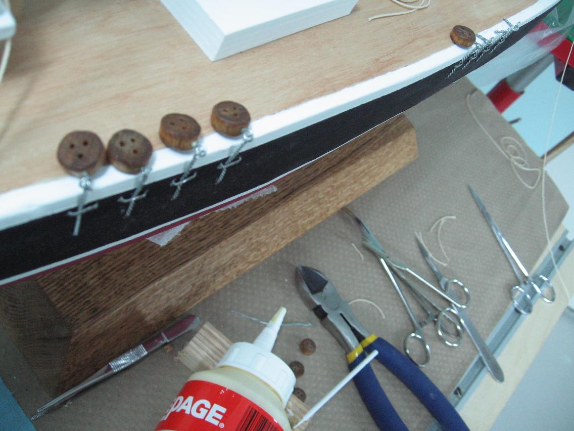
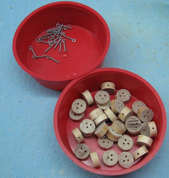
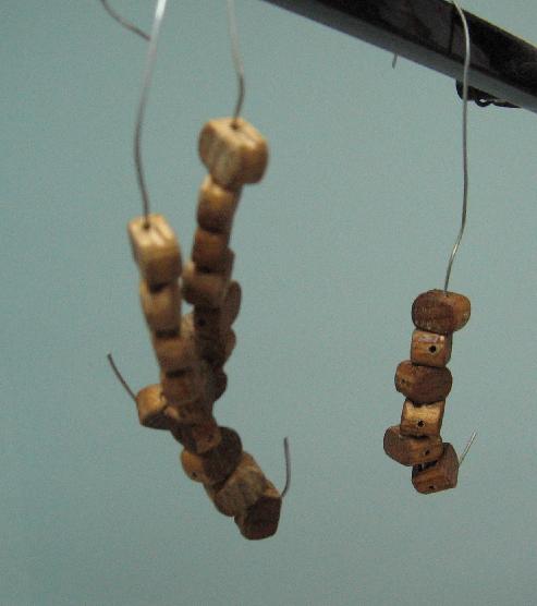
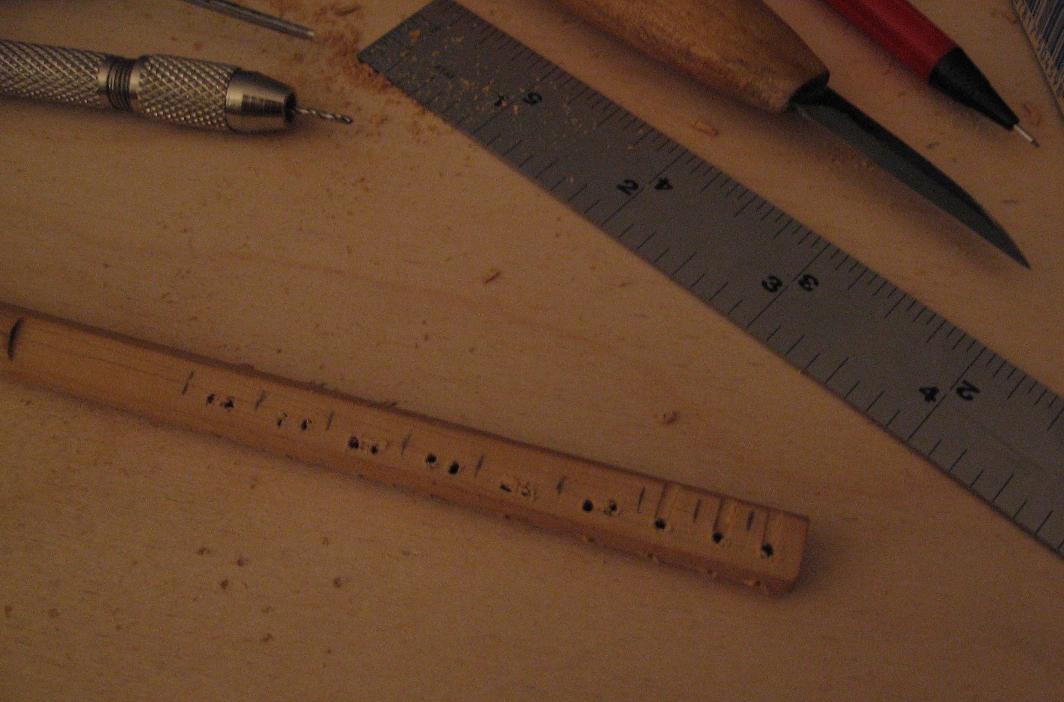
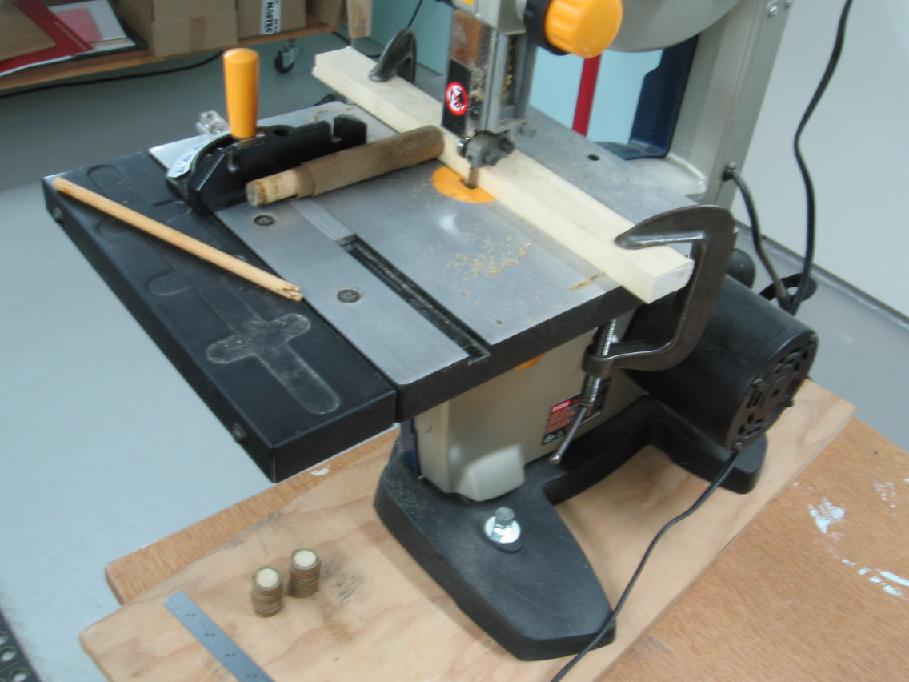
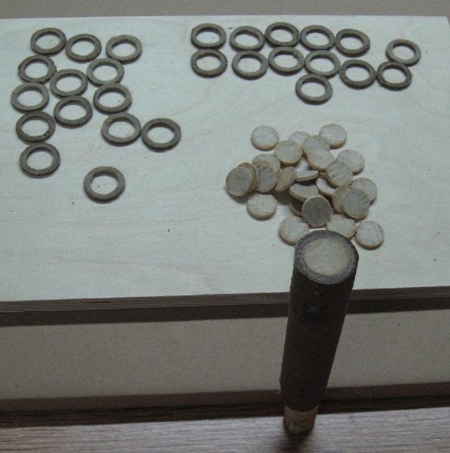
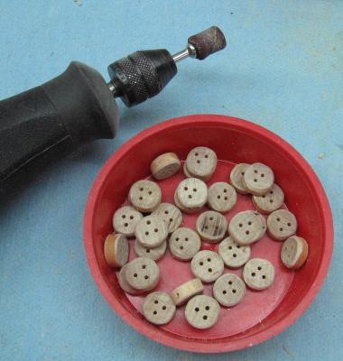
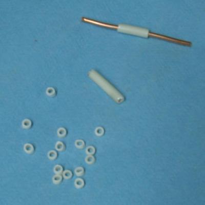
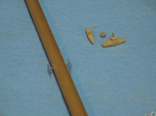
Wednesday 17 December 2014 Started making my Deadeyes (32) Using 7/16" dowel I first cut them longer than needed then sanded them back as square as I could on the disc sander Set them up one at a time in my vise, pencil marked where the holes should go (by eye) and drill through with my dremel (hand held) Then I marked and drilled the eyelet hole in the side They all need sanding and staining (tonight) I then had to make yet more eyelets (16 so I made 20) I then managed to reeve a line through one of the three sets of boom blocks This was harder than it should have been I need steadier hands! Coiled the line temporarily just to get it out of the way as they aren't many but there is a mess of them gathering.


-
mini drill chuck for those small drill bits
AON replied to AON's topic in Modeling tools and Workshop Equipment
Thank you Jack That gets me down to a #67 bit I'll have to check the model number of my dremel to see if it will work with the press All and all my dremel does not run at a very slow speed (cannot get down below about 1000RPM) where as my big drill press will... and I've been looking for replacement rotor brushes as they are getting worn again and now no one seems to carry them locally. I suppose I'll need to buy these online also at some time. *********** Toni, I've checked locally and seems there aren't any re-sharpened bit suppliers willing to reveal themselves I suspect they would likely buy from the US and mark it up substantially -
mini drill chuck for those small drill bits
AON replied to AON's topic in Modeling tools and Workshop Equipment
Thanks guys, My dremel is quite old and I am not sure it would clamp properly as the new dremel's seem to have a space aged shape to them. Also I cannot find a dremel chuck for the smaller bits... all these would work in it, or my drill press. I like the $US2.99 price of the Model Expo attachment for the price. I'll have to check out the shipping costs to get it to the Great White North. The McM-C items seem like a nice pair, the larger one locking with a key and the smaller one by finger (or pliers?) Would still like to hear more opinions if there are any Alan -
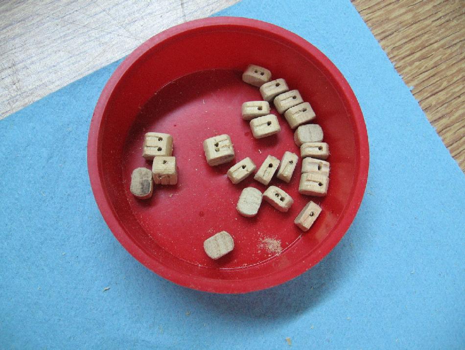
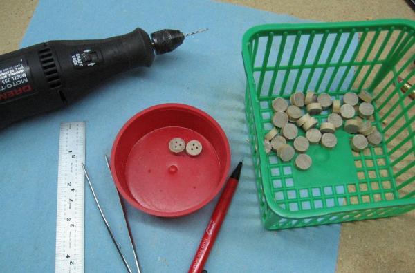
Having attempted making my first batch of rope blocks, drilling many many MANY holes with a pin vise I have decided I need a mini chuck for my drill press for the next time I attempt anything like this. I just found these two products on the McMaster-Carr website Has anyone used them? Is there something better out there? Alan MMC 28055A71 drill chuck No 70 - 1_4 drill.pdf MMC 30505A5 drill chuck No 90 - No 60 drill.pdf
-
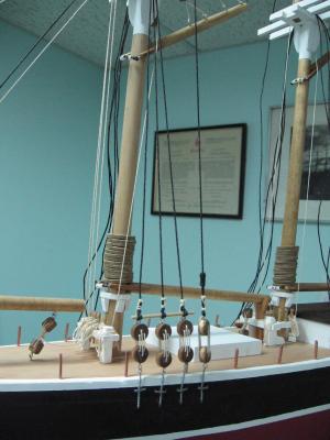
Tuesday 16 December 2014 Corrected the block issue on the gaffs Started installing the running rigging Gaff, Boom fore and jib halyards run through the blocks Broke two blocks as the eyelet hole was too close to the edge and weakened it As I handled the block to thread the line through it twisted and ... broke I will not make blocks quite like this again Not wanting to be negative but realizing the amount of work remaining I doubt it will be done this Friday

-
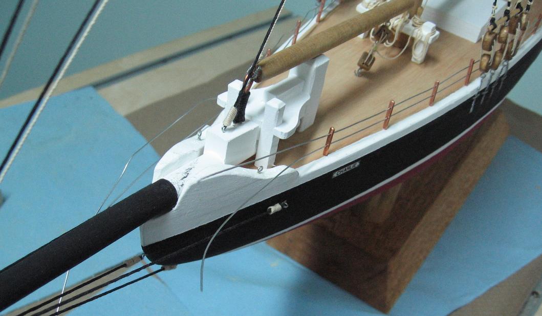
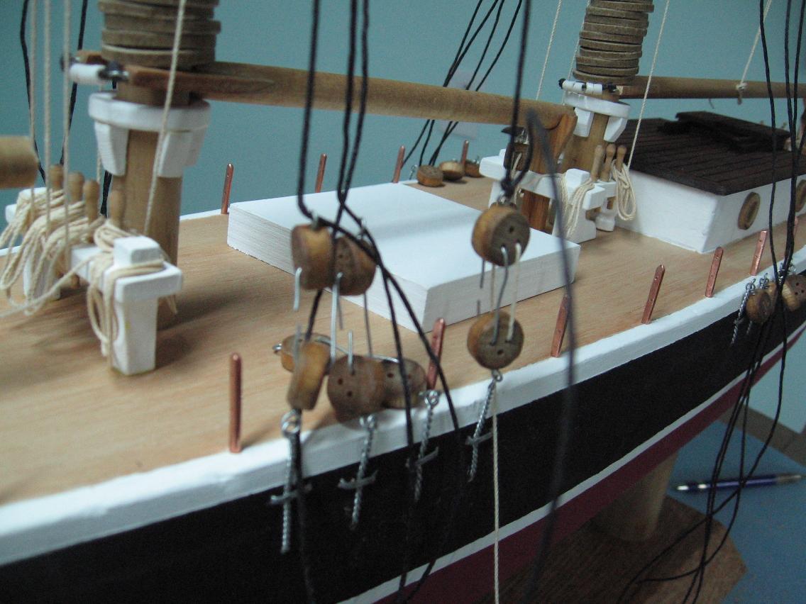
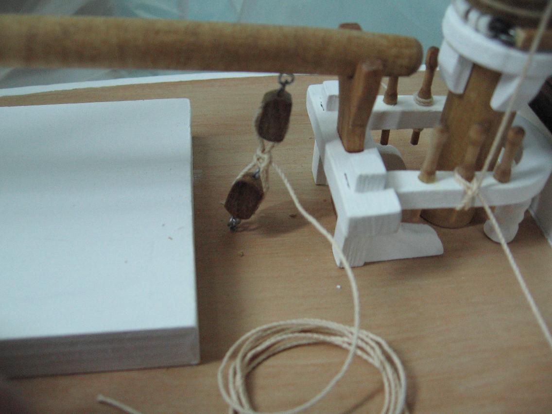
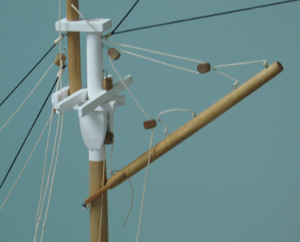
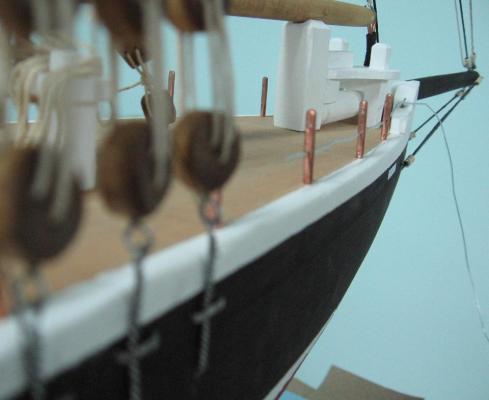
Definitely the last photo The blocks on the boom should connect to an eyelet The line installed should not pass though the sheave Eyelet hole is in the bottom of the block No eyelet installed I'll cut the line off completely, install the eyelet and re-assemble. BTW The knot used on those is what my dad (a sailor) called a surgeon's knot Probably not the proper name as he was prone to some tall tale telling (blarney) He did help me learn splices and other knots. For this one you start with an overhand knot but pass it through two more times for a total of three before you pull it taut This knot is not likely to come loose (but I put a dab of glue regardless) He showed me this many moons ago (as a young gaffer) when fishing.
-
Dang it! I've made a misteak (yes, yet another one) Fighting the urge to delete the image providing proof (can you see it?) The mistake is mine, I own it. Thanks be to the Big Guy looking over my shoulder it is an easy fix. If you cannot see it I will point it out after it is corrected tonight.
-
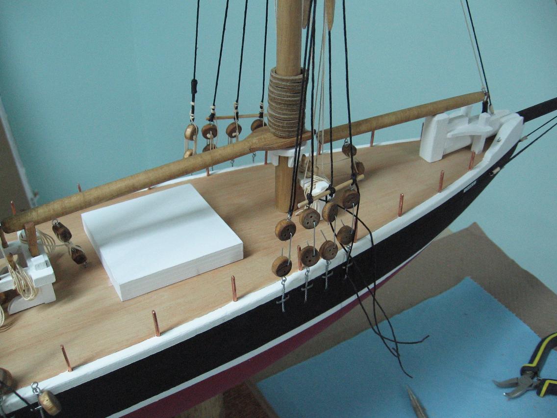
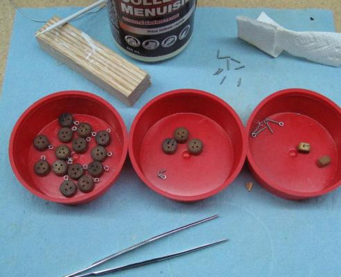
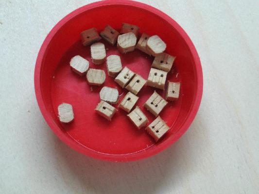
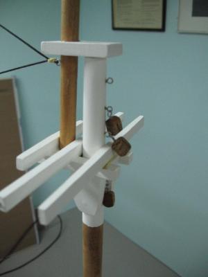
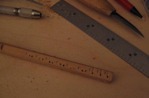
Monday 16 December 2014 Managed to install almost all the blocks Just the few on the deck for the booms left to do Once again the photo tags explain everything I had cut all the pieces and put them in the plastic holder you see in the photos, took them over to the sander and placed them on the desk. Moments in to it I knocked the darned thing over to the floor and two blocks disappeared... never to be found. So I had to make two more. During sanding one block broke... the only one. Had to make it over also. On the whole if I were to grade my first attempt at making blocks from 1 to 10 .... I'd give it a three. They look pretty good to the untrained eye... but then I saw blocks made by a master and I have a long way to go. I definitely need a better way to drill the tiny holes more accurately.


-
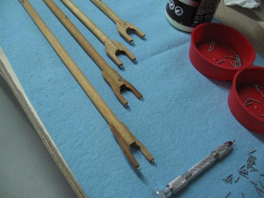
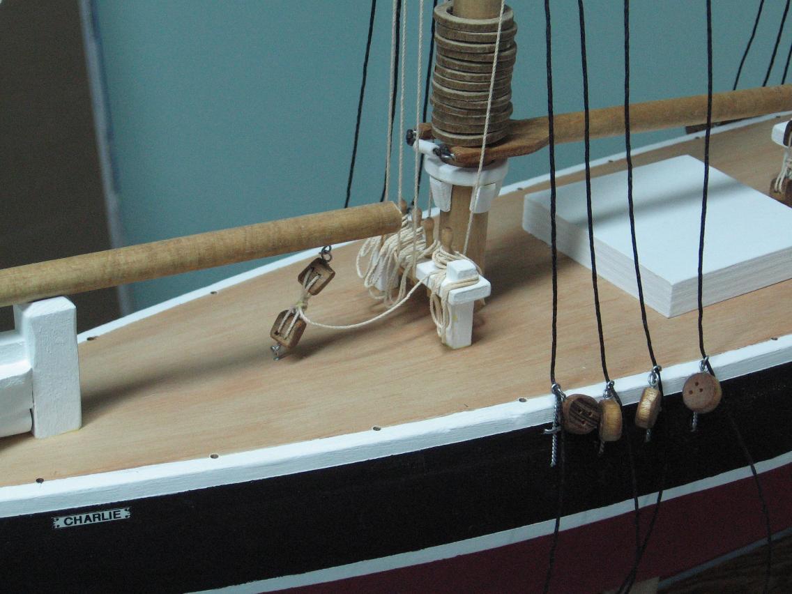
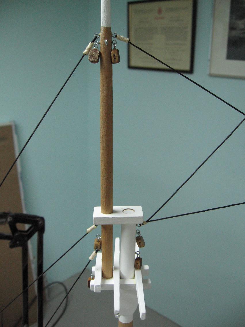
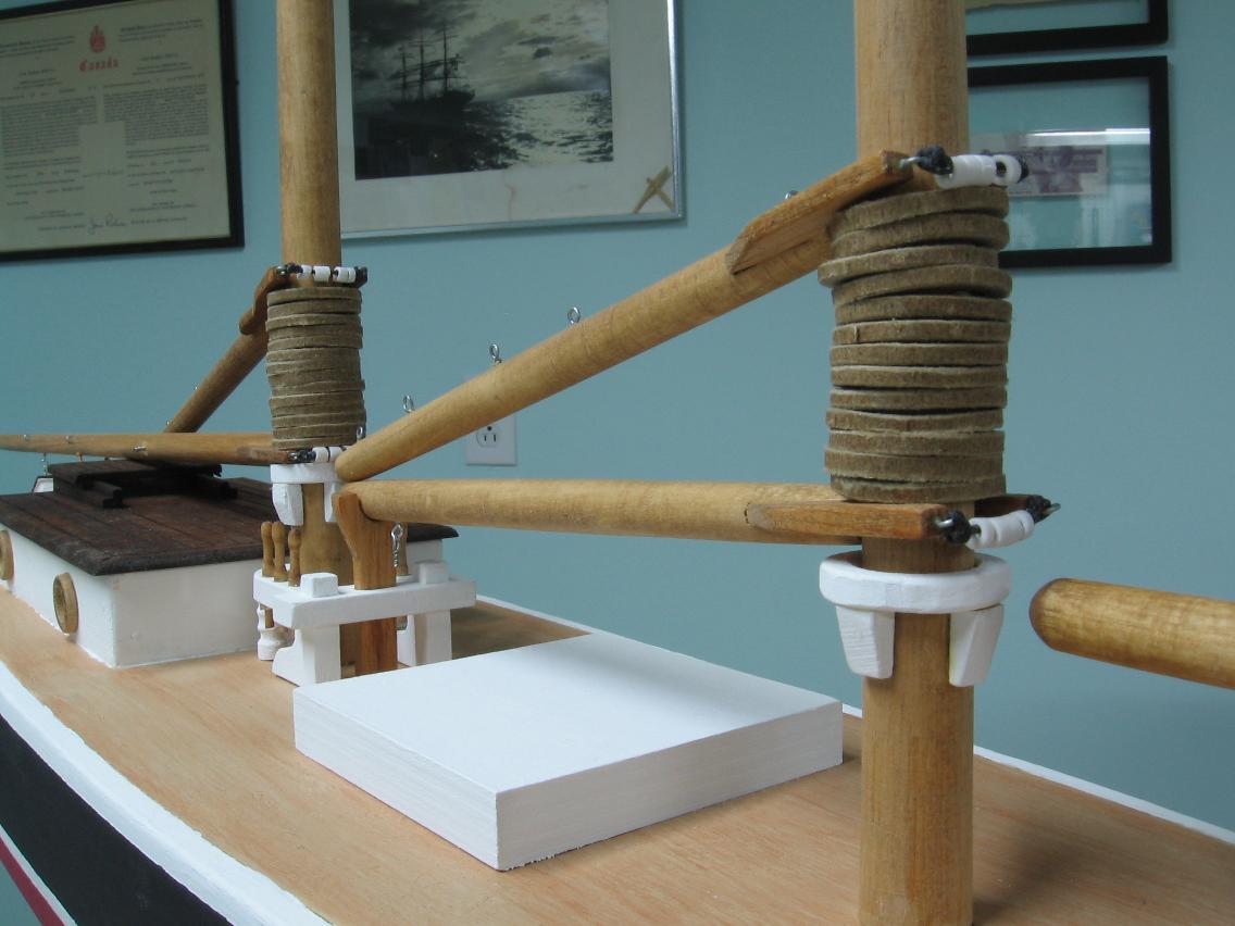
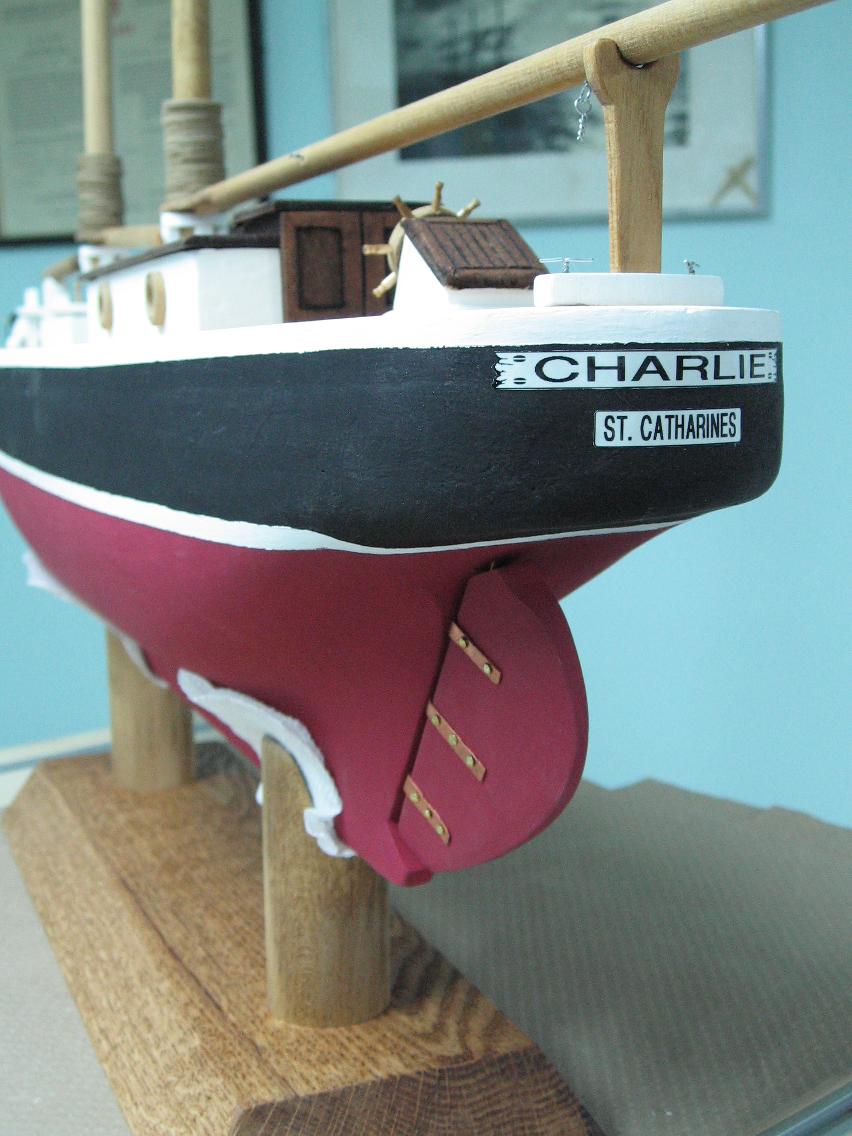
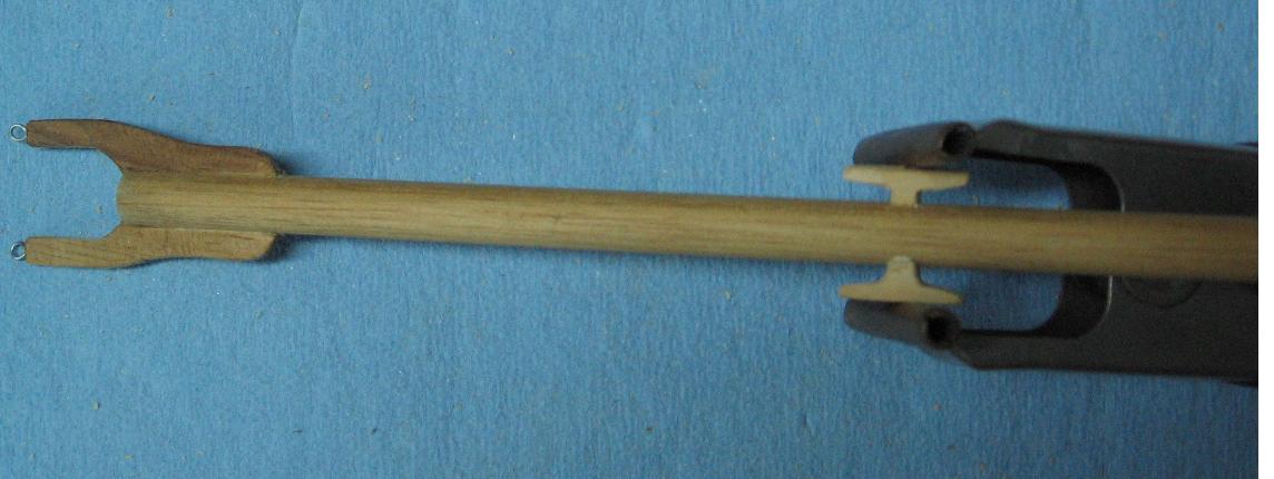
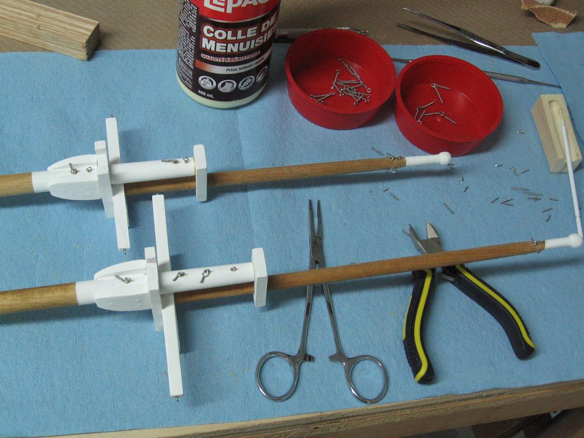
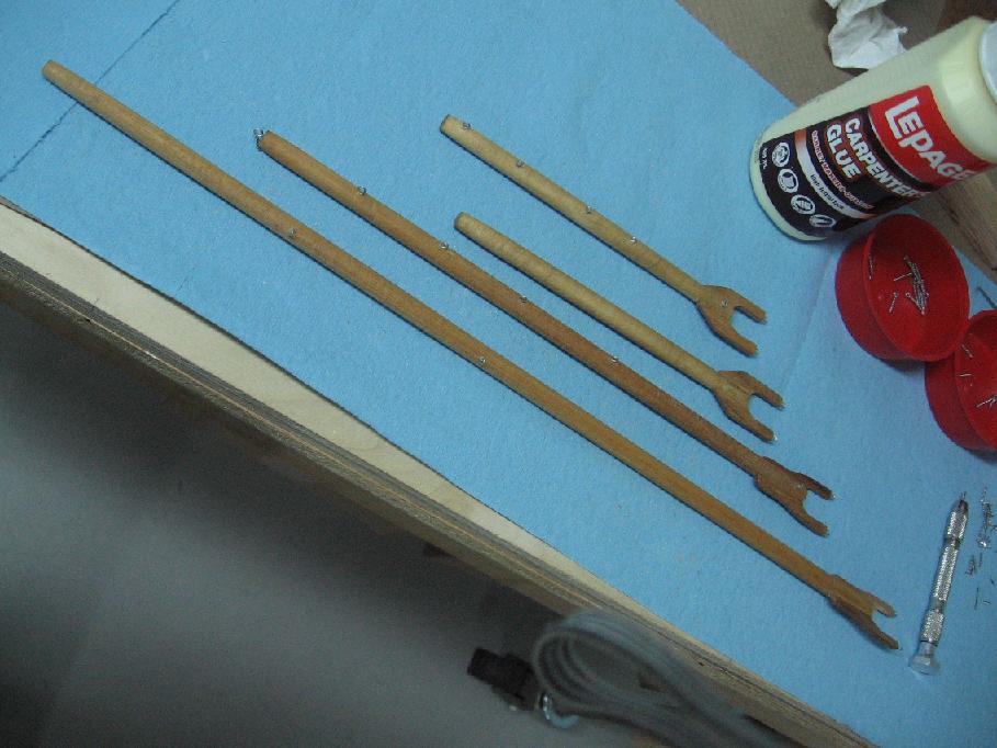
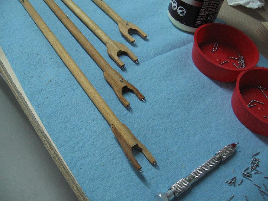
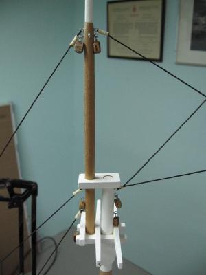
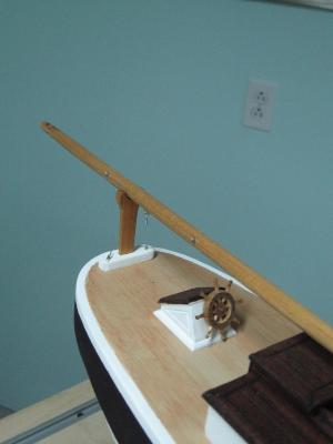
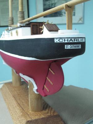
Saturday + Sunday 13+14 December 2014 I got quite a bit accomplished... photo tags help explain Problems encountered: - When installing the masts I discovered the cross trees on the foremast were not quite horizontal. I had to saw the trestle tree loose from the cheeks to correct the error. - I discovered I attached the cross trees incorrectly and decided to install a third rather than attempt to remove the shorter one and rework the trestle trees - The jaws on the main boom were too long and needed to be shortened. - I had trouble with applying the name to the hull as my methods were terrible. My darling wife suggested using our office labeller. This looks better than what I was trying to do. - I had missed installing an eyelet which resulted in my standing rigging (one line) being incorrect. I love doing things twice! - My finger is raw from all the pin vise drilling... the knurl finish on the pin vise is a bad idea. I have learned I need much more practice with the techniques to get better. I hope my blocks will be okay but even these will show a lack of skill. Looking at David Antscherl's block making method in "The Fully Framed Model" would likely have been a better approach. I'll being working on this to get better. Meanwhile, my schedule is to be done this week for a Friday delivery. Hope I succeed!

- 129 replies
-
- 10
-

-
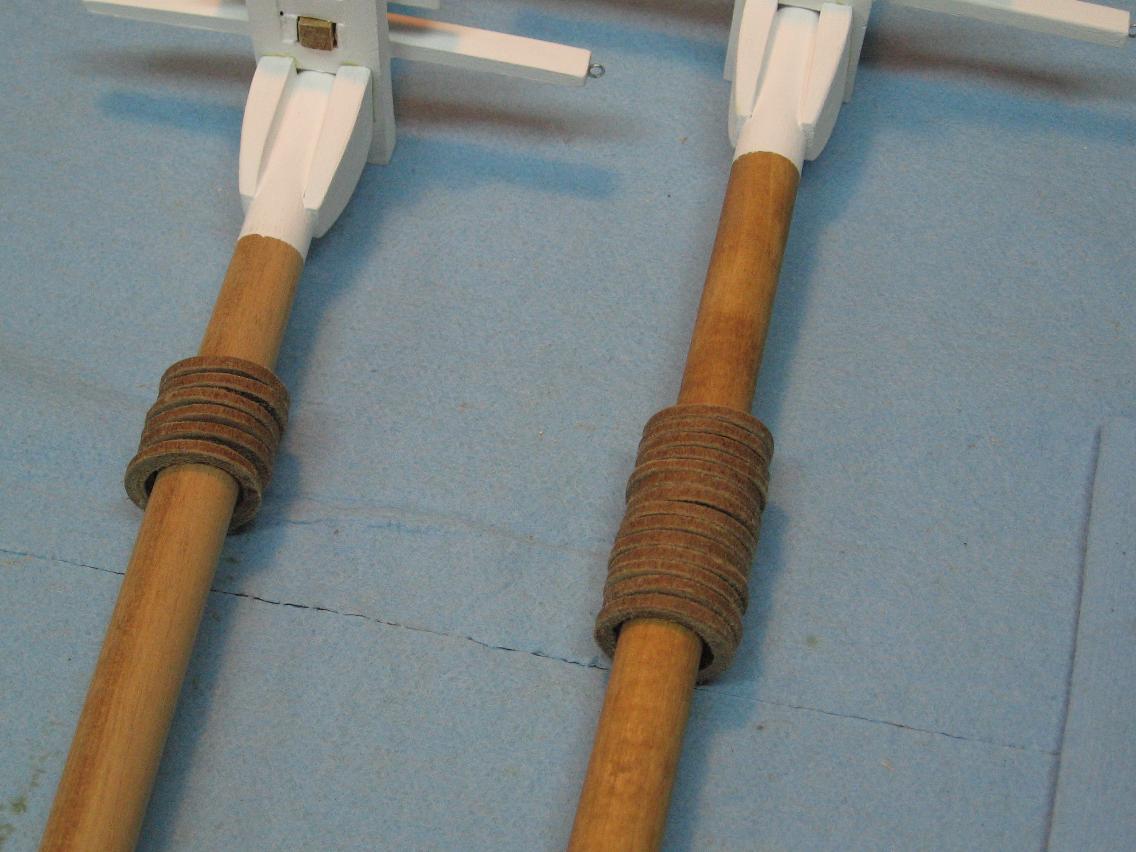
Thank you Dee Dee the photo does not do it justice it looks like real wood grain! Alan
-
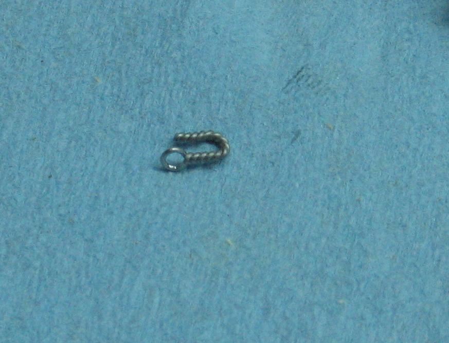
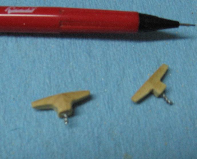
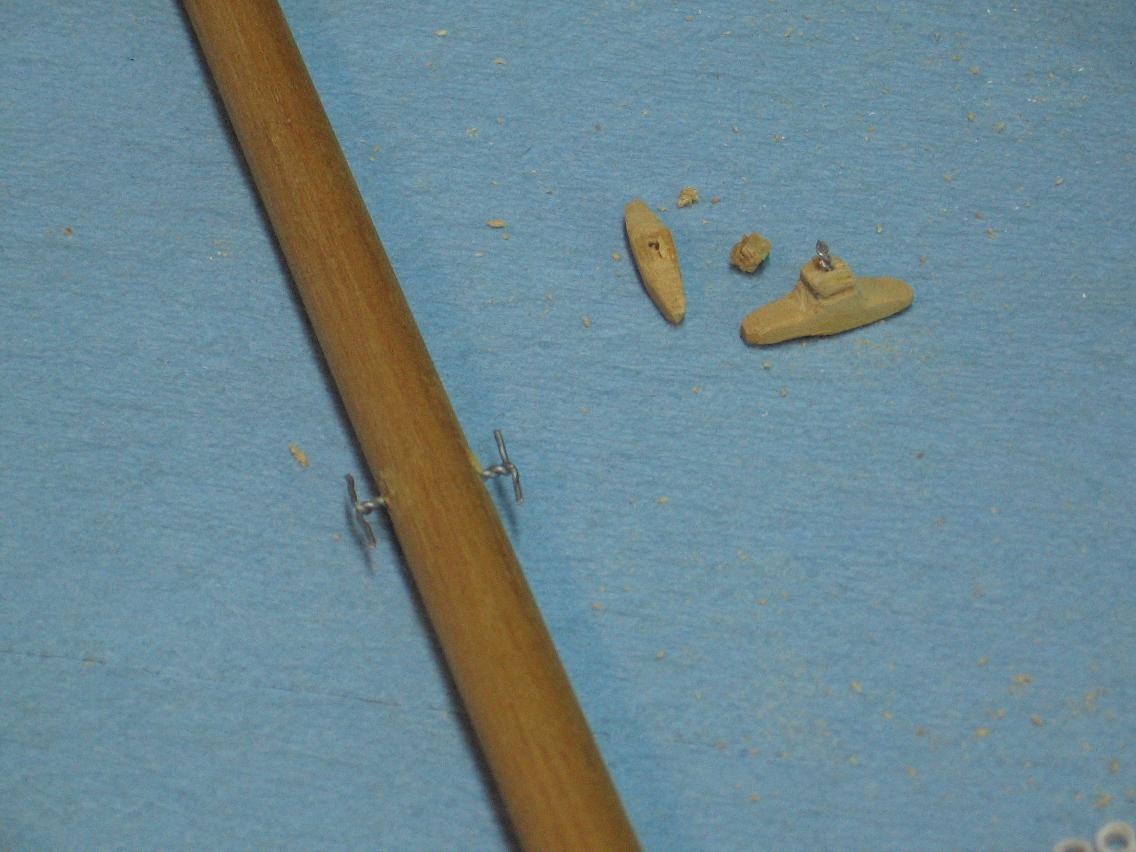
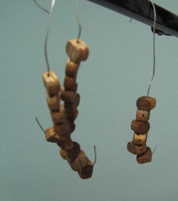
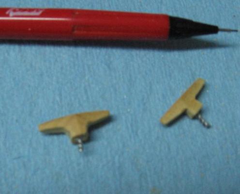
Thursday 11 December 2014 It didn't feel like I accomplished much made two very nice wooden cleats to mount on the main boom Drilled and pined Glued to the boom Clamped then they broke Decided to follow the KISS principle and made them out of the 22 gauge wire Started smoothing/sanding the mast hoop edges I am very happy with these They look like real wood (well paper is a wood by-product) and they contrast very nicely on the mast I have 7 more to go on the foremast to be done with them

-
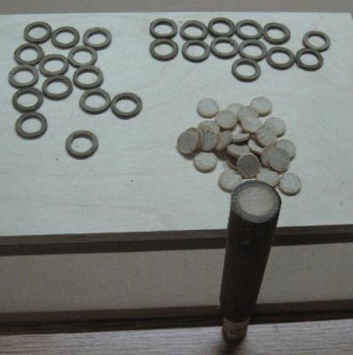
Wednesday 11 December 2014 The roll of stained and glued newsprint had dried considerably through the day, not yet 100% but enough to allow cutting... and I was able to reinsert the dowel! I cut 14 mast hoops for the main mast and 13 for the foremast ... with material left over. They need to dry more and as they are thinner and open I imagine this will be quick. They require some sanding on the edges. I also installed eyelets on the masts, booms and gaffs