HOLIDAY DONATION DRIVE - SUPPORT MSW - DO YOUR PART TO KEEP THIS GREAT FORUM GOING! (Only 68 donations so far out of 49,000 members - Can we at least get 100? C'mon guys!)
×


AON
-
Posts
2,861 -
Joined
-
Last visited
Content Type
Profiles
Forums
Gallery
Events
Everything posted by AON
-
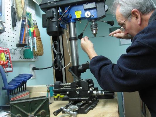
 Saturday 22 November 2014 (PART 1) Completed the handrail stanchions - drilled - deburred - reclamped in vise to straighten face and turned 90° to straighten edge - drilled again - polished with wire brush wheel on dremel with my dremel clamped in a vise I also sanded the deck and filled cracks and dents It will need another sanding
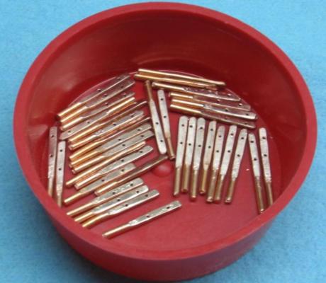
-
WOW!!!
-
Further progress will come to a crawl as I'll be back to working overtime this week.
-
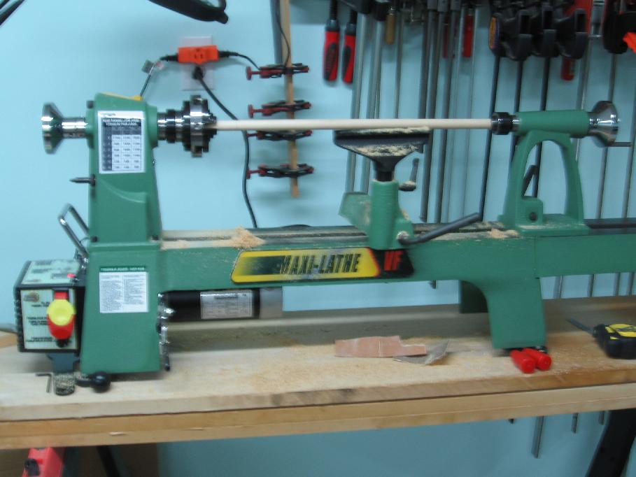
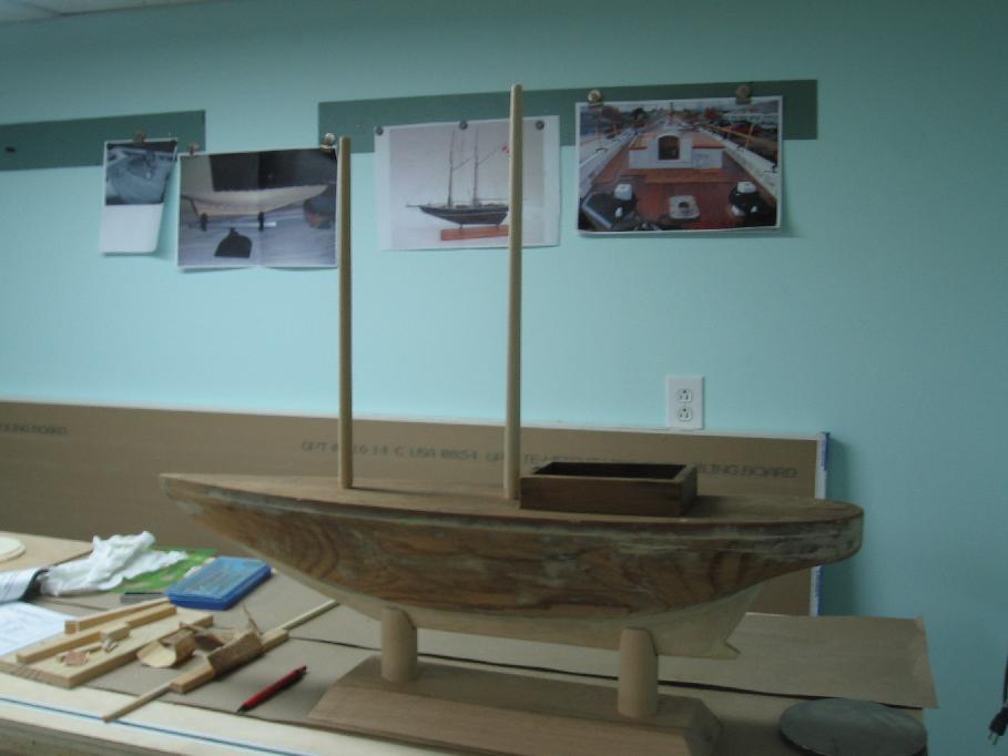
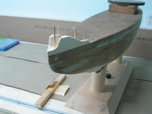
Sunday 16 November 2014 (Part 3) Worked on the masts Calculated (by ratios from an image) the scale length and diameter of the masts 5/8” diameter, 14.1” and 15.5” long Calculated the rough locations and set angle of the masts Set the hull up to my drill press at 3° angle and drilled two ½” diameter holes for the masts to be stepped into. Found some 5/8” diameter dowels and cut them 4 inches longer and mounted them in the lathe Turned the deck stepped fit portion 0.510”+ diameter to fit (Tapered the lead end to assist assembly) Turned the top end to +/- 0.400” diameter Tapered the length between and sanded in place on the lathe. Dry fit into deck (not driven in as I would not get them apart again) to check. I am happy with these. I have not made the cabin port hole pieces yet.


-
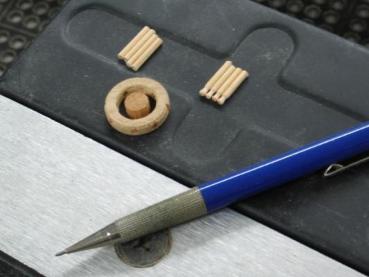
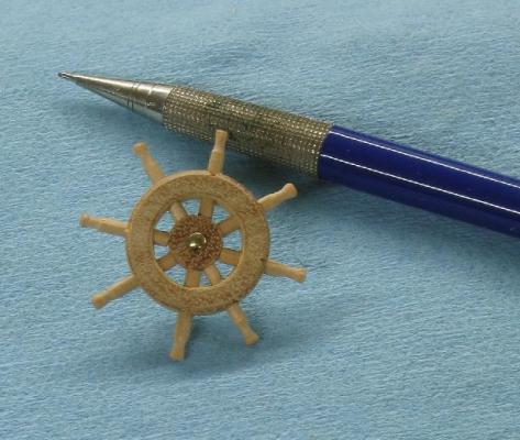
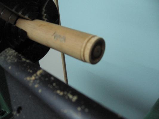
Sunday 16 November 2014 (Part 2) Made a new ships wheel Re-drilled the spoke holes Turned the wheel on the lathe and once again the hub vaporized This time I saw it happen. The holes (thru what would be the hub) remove all structural integrity in the material and it tears apart. Did my final cut to part it from the dowel on the band saw Cut a smaller dowel to make the hub Of course it was not “square” so I drilled a shallow pocket hole (big enough to fit the hub into) in a piece of scrap and used it to hold the hub square against the disc sander to true it up. Cut my spokes to length Installed them in my drill press chuck and used small files to shape the handles. (I should be wearing safety glasses but it was so tiny I couldn’t see what I was doing… I had to look over my lenses to focus… getting old sucks) Dry fitted and remarked the shorter lengths for the spokes. Drilled another pocket holder and disc sanded the spokes square to length Reassembled and glued (small dabs) from the backside. Drilled and installed a brass pin nail as the hub pin.
-
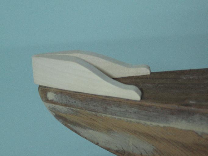
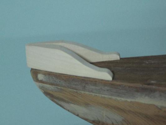
Sunday 16 November 2014 (Part 1) Drilled and dry pinned the cowling to the bow Sanded to finish shape
-
Thank you Druxey It doesn't look like much but it is making good use of scrap pieces and surprisingly did the job I admit I was concerned it might fly apart.
-
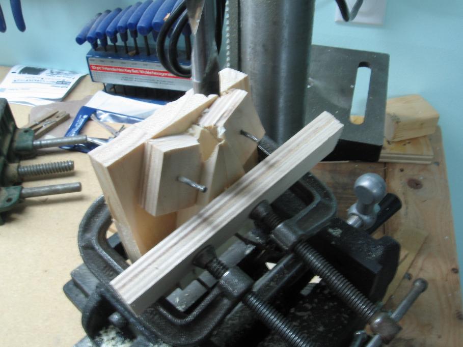
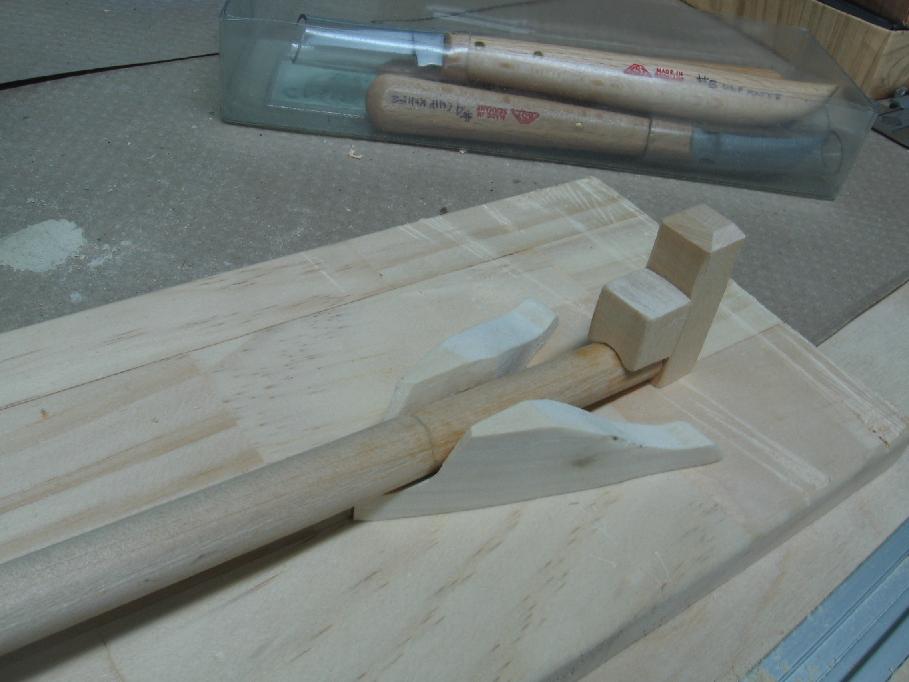
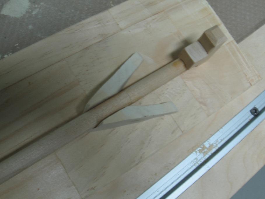
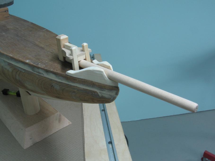
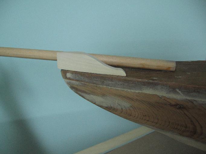
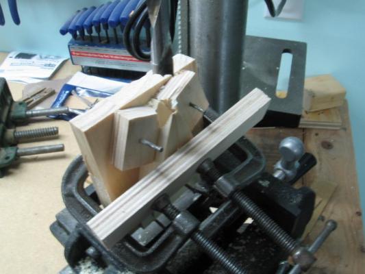
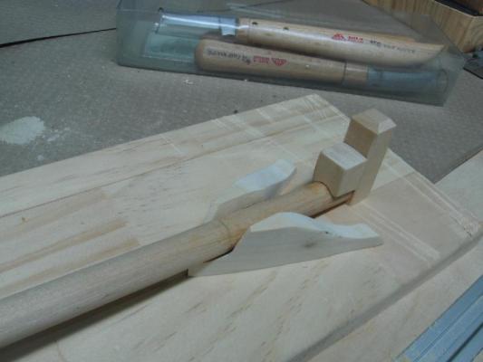
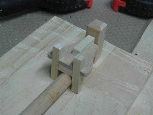
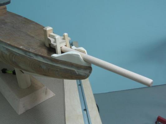
Saturday 15 November 2014 Today I find myself a year older but not one iota smarter! I completed my test piece on the lathe and was very happy with the results so I decided to do the ships wheel. I set my predrilled doweling up and began cutting away. The centre hub, a crucial part of the wheel, vaporized in front of my eyes. Never giving in I decided I could make a new hub so I carried on. Completed the outer part and set it against the wheel gear house. Decided it was too thick so I sanded the two faces to thin it down. This is when it happened. I thought I had learned the lesson of knowing when to say ‘when’….. it was now too thin. Into the trash bin! Time for a ‘do over’. I started on the bowsprit cowling. Set up the piece on my drill press at what I determined to actually be closer to 6-1/2° angle (4 separate readings) and plunged into it. This, to my surprise, worked out okay (photos below) I will eventually drill, pin and glue this to the deck and then sand the outside face to blend in to the hull. I then worked on the Bowsprit Bitts and Samson Post assembly. Having completed them, dry fitting to check I moved on to shaping the bowsprit (photos below) I mounted the bowsprit to my lathe and turned/tapered it to rough shape. I then finished it on the lathe with sand paper. Dry fit it all together and found I needed a wee bit of shaping on the cowling. Now I am happy. Went to Michael’s (hobby & craft store) and bought some brushes and paint (primer, black, dark red and white). Also picked up a tube of wood stain at Canadian Tire which I am hoping will work better on the cabin roofs. Once I have the masts located, all holes drilled and the deck sanded it will get a good cleaning and then a paint job. But for now I need to redo the ships wheel and make four port holes for the cabin.

-
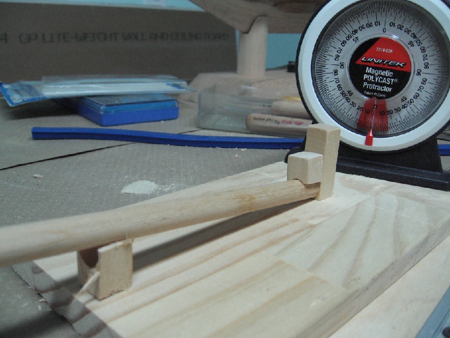
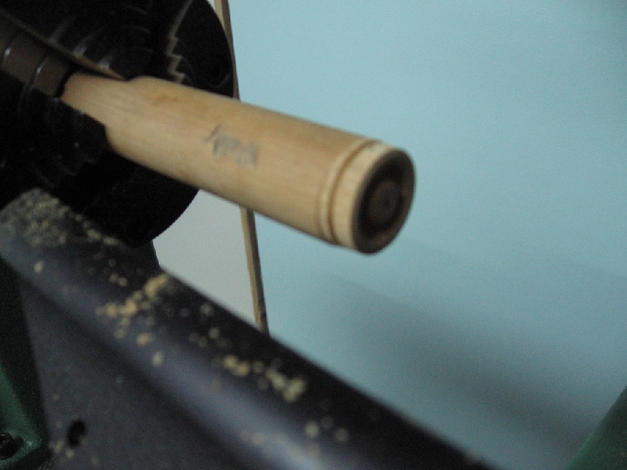
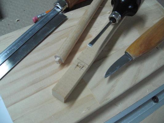
Friday 14 November 14 Managed to recut the Samson Post (still requires some shaping in the top 1/3) - Dry fitted with Bowsprit - Set up to measure angle (8°) of assembly so I can set up the bow cowling angle for drilling the bowsprit hole Also did some practise cutting on my wood lathe for the ships wheel shaping - Turn round - Cut out centre hub - Mark part line I will finish this one to make sure I am happy with it and then do the real one that has been predrilled for the spokes As this looks like a good port hole cover for the cabin I may do the same thing with smaller dowelling Hope to accomplish considerably more this weekend.

-
Review of the Admiralty Model Sail-making Workshop, NOTL
AON replied to AON's topic in Masting, rigging and sails
Framed and Hung Decided to add a bit of artistic look by cutting it clear of the bolt rope with a ragged edge The frame is see through both sides so I can look at the reverse if I need to refresh my memory of the work on that side.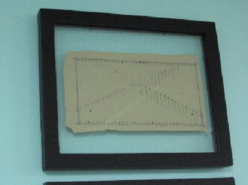
-
Sunday 09 November 2014 Redoing the Samson Post as I decided the first attempt wasn't good enough Also clamped down the bow cowling or faux gunwhale in readiness to drill the bowsprit clearance hole

-
For those following and wondering what happened to my progress here... I have switched gears and have been working on the schooner CHARLIE for a friend. Hope to be back to my first order of business early in the new year.
-
Progress may slow down as my working associate (salesman) brought in a few orders and it has me working overtime. At least I can blame it on him this time.
-
Good morning world I am feeling exceptionally chipper this fine Sunday morning having spent two days attending the sail-making seminar held in historical Niagara on the Lake (a 34 minute drive for me). What a fantastically wonderful experience! I am relatively new to all this and felt I should mention the comradery you feel from the help you get on this site DOES actually extend to real life meetings. Of course my sorrowful looking first attempt at a sail is nothing to brag about but I have never learnt so much about 17th century sails (and other off menu ship building tidbits) that I just had to post a review. I am actually thinking of framing and hanging my first miserable sail in my workshop as a reminder of the experience. Just felt I had to share this feeling I am having. David Antscherl is a wonderfully knowledgeable and patient instructor. Unfortunately Greg Herbert could not be there; I was so looking forward to meeting the gentleman. I said it before and I'll say it again (and again, and again ....) what a wonderful site and fantastic group. Thank you. Alan
-
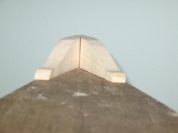
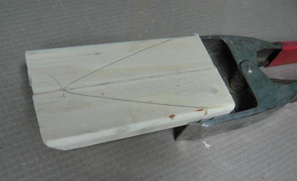
Tuesday 04 November 2014 cut the shape with my scroll saw lightly sanded needs more shaping and a clearance hole for the bowsprit but here is the idea by my calculations the bowsprit should be approximately 0.4666" dia and 4-1/2' extension beyond the bow the dowel is 7/16" dia = 0.4375" PS: forgot to mention the warts... I cut one piece backwards and had to start it all over


-
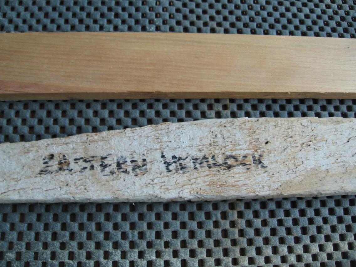
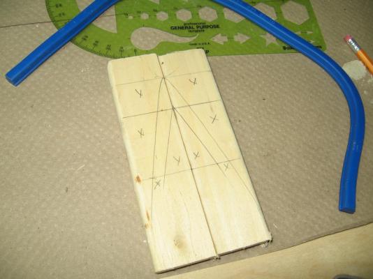
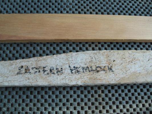
Had some time to kill this morning before I go to the doctor's office to get my flu shot so completed the outine on the addition for the bow and took some photos. I will cut it out tonight or tomorrow and will scallop it to suit the bowsprit when that item is ready. I also took a photo of the lathing material before and after planing so you can see what was revealed under 100 years of hanging on a wall under plaster.
-
16 sided figure is a hexadecagon (Google is a wonderful tool)
-
If you could only hear me laughing ... you nailed me perfectly! Problem is, usually my plans make perfectly good sense in my head but somehow don't always follow my plan in real life. As Druxey would say, make sure your carving Knife/Chisel have a really good edge before you begin It makes a world of difference.
- 968 replies
-
- 1
-

-
- hahn
- oliver cromwell
- (and 1 more)
-
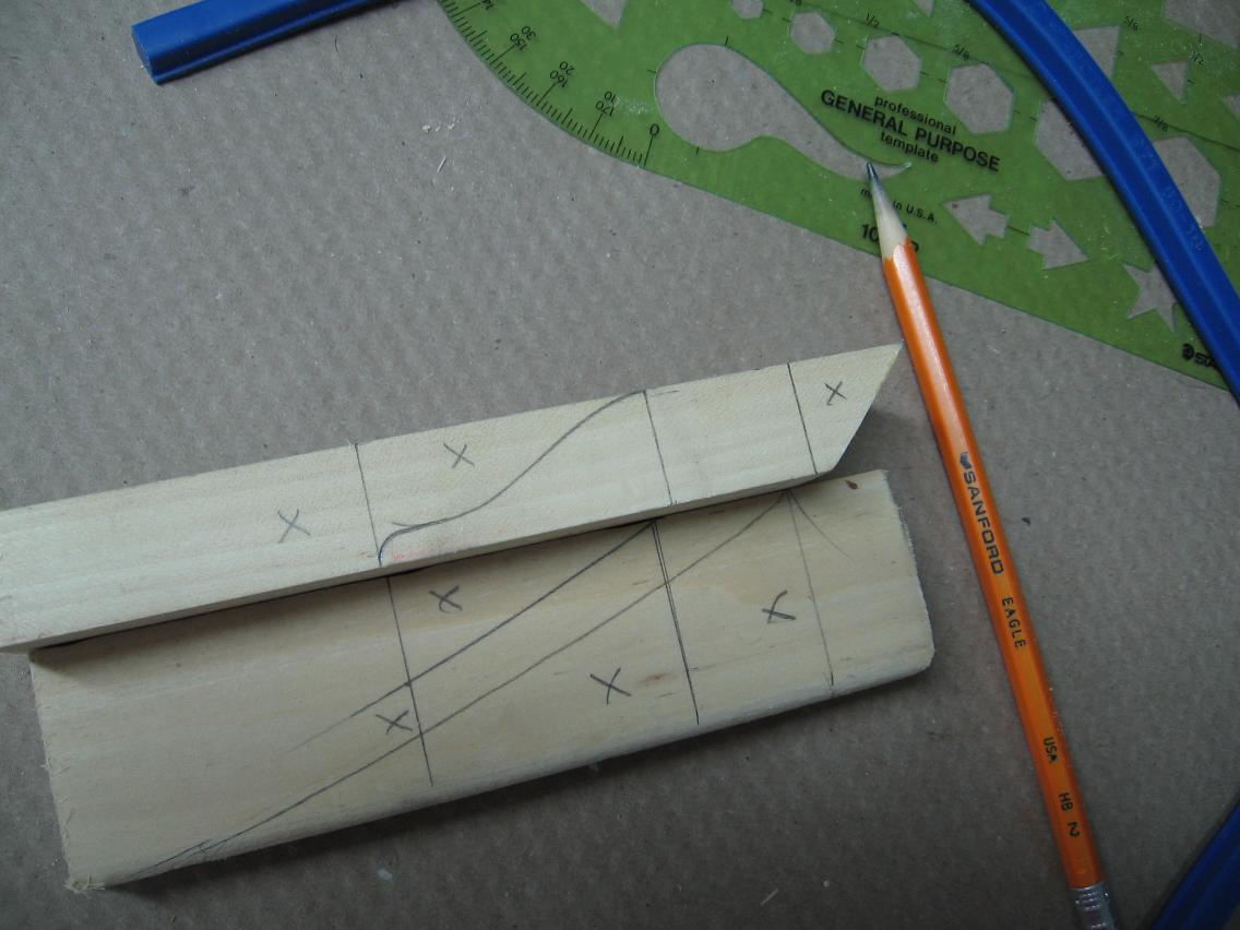
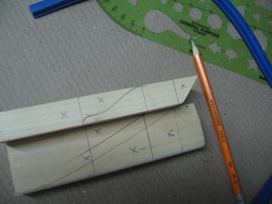
Monday 03 November 2014 Completed drilling all the stanchions Had to scrap five halves as the holes were too close to the edge Flattened new pieces and will drill them tonight. Also started on a bow gunwhale/combing to assist in holding the bowsprit in place Not much to look at/show as yet. Just traced the outline onto scraps of maple. Developing my plan of attack in my minds eye. Also The plaster wall lath my son is tearing out of his home was thought to be ash but in fact it has been found to be eastern hemlock. I passed a short piece through my planer and edger last night and I am left with a beautiful finished piece 0.32" thick (8.1mm) x 1.37" wide (35mm) It has got me as excited as the oak base had. I think I'm in love. I'll be grabbing more of this from his wood pile before he burns it all!
-
Mike If I may make a suggestion .... Think of it as an opportunity not a mistake! You get to solve a puzzle by having to think outside of the box. BTW - I might have done the same thing Alan
- 968 replies
-
- 2
-
-
- hahn
- oliver cromwell
- (and 1 more)
-
I'll be watching also! I know just how disruptive any move can be. I am just getting use to where all my toys... I mean tools are stashed now
-
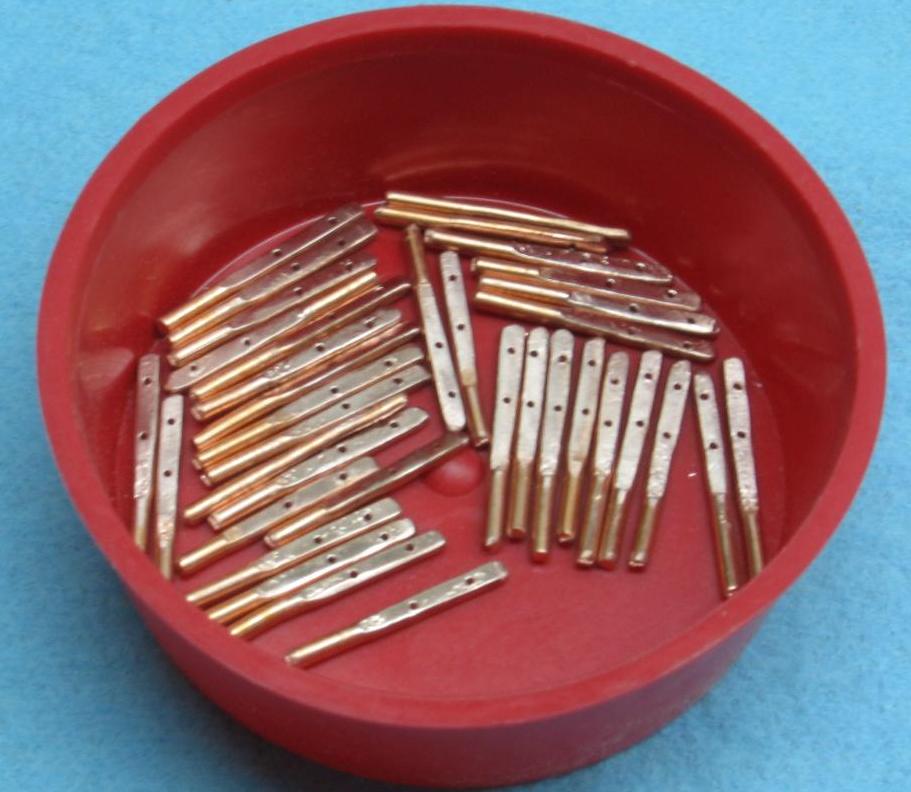
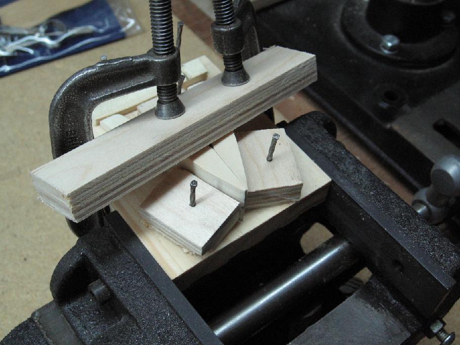
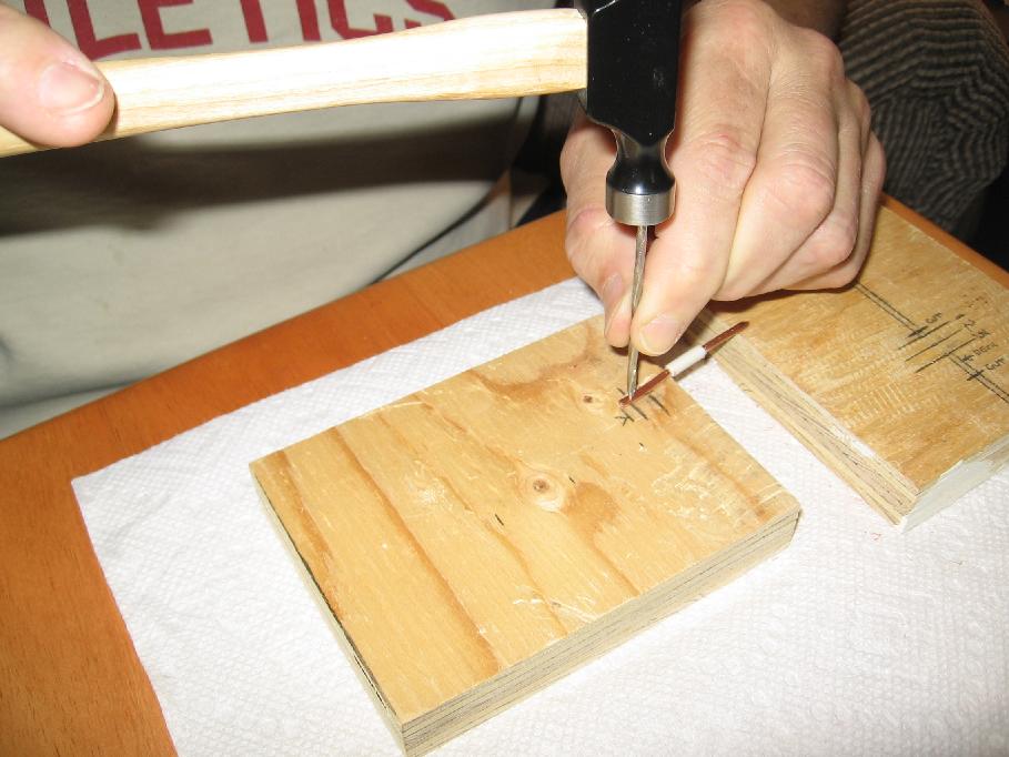
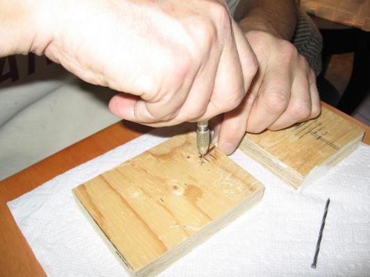
Sunday 02 November 2014 Managed to get all stanchions (and a few spares) ready to be drilled through. First I punch marked the hole location with a nail I ground a sharp point on. Then I drilled a dimple into the stanchion with a #66 bit in a pin vise so that when I go at it with my dremel the bit will not wander. I will start drilling them all through tomorrow night.

-
Thank you! I was very concerned with the possibility of having taken too much off one side when shaping or ending up with a wiggly snake like surface. It is not "perfect" but I believe it is because I know where the "issues" are. I dare not shape it any further or my concerns will come true. Stripped the jackets off the ends of the wires last night for the stanchions. Going to clamp the flats, drill the holes, shape the tops and cut into two pieces today. Thinking ahead to the rest of the deck and bowsprit.
-
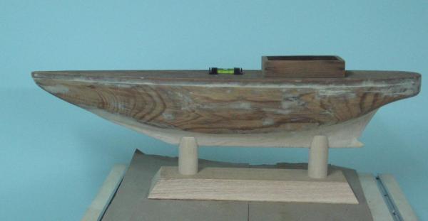
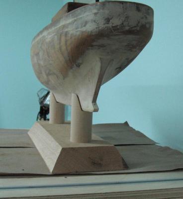
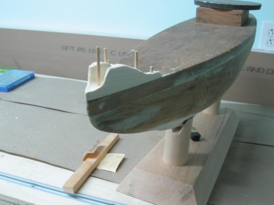
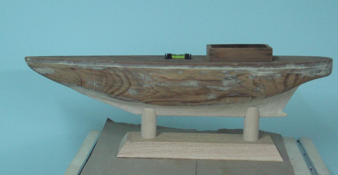
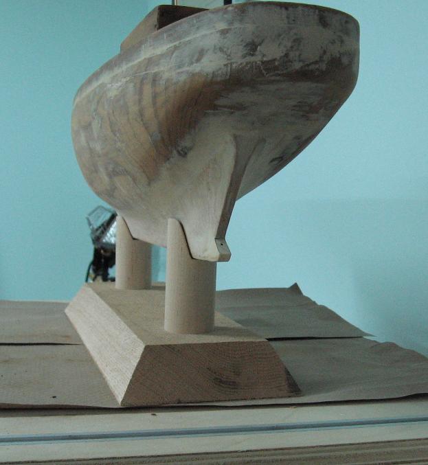
Saturday 01 November 2014 Completed the base also Rough cut the vee notch with my bandsaw then rasped, filed and sanded Had to cut 1/8" off the longer aft post to have her berth level I have planed and sanded the base after these photos nothing is glued as yet The oak looks fantastic... I think I'll stain it and paint the posts white Very sturdy! I am happy with this.