Check out our new MSW Sponsor Innocraftsman
×


AON
-
Posts
2,840 -
Joined
-
Last visited
Content Type
Profiles
Forums
Gallery
Events
Everything posted by AON
-
 Presently busy realigning all previous station frame outlines to intersect with the upper rabbet line. Amazing just how much an error will teach a person
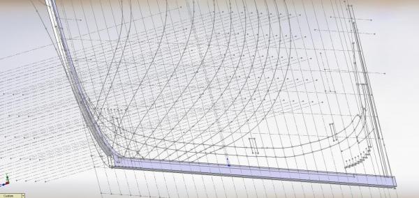
-
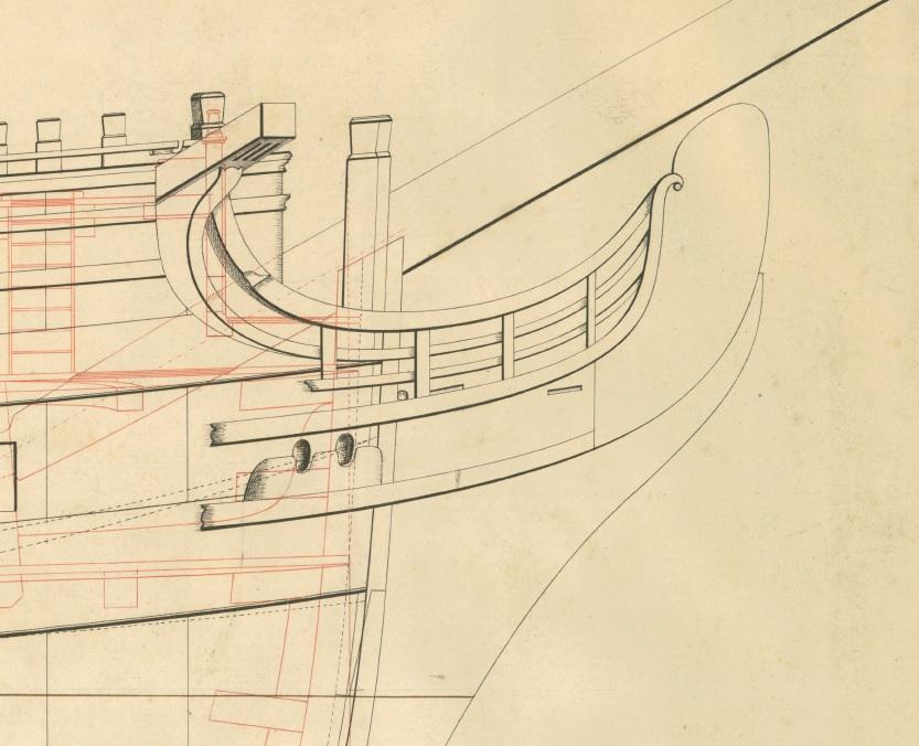
I began sketching in the deck elevations at the bow and stern and noticed the round house deck is slightly elevated (above) the upper deck. Having studied the Vanguard models built and in progress on the forum I note they are at the same elevation on them. I also have thumbnail images of the Edgar and my plans of the Goliath locate them at the same elevation. Ree's plates show it as being on the same elevation. Would anyone have an explanation why the Elephant's as built plans are so different?
-
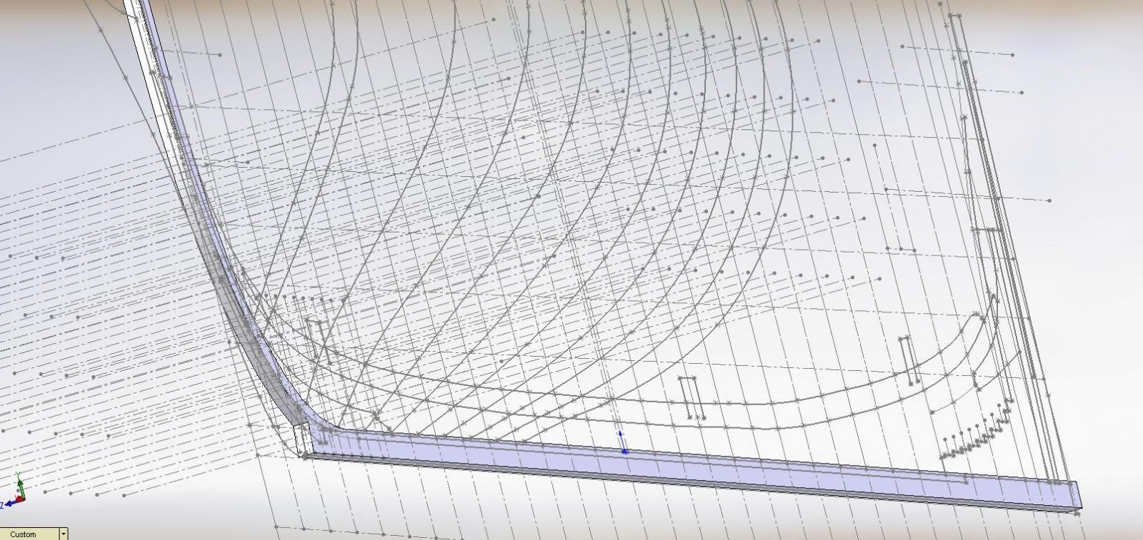
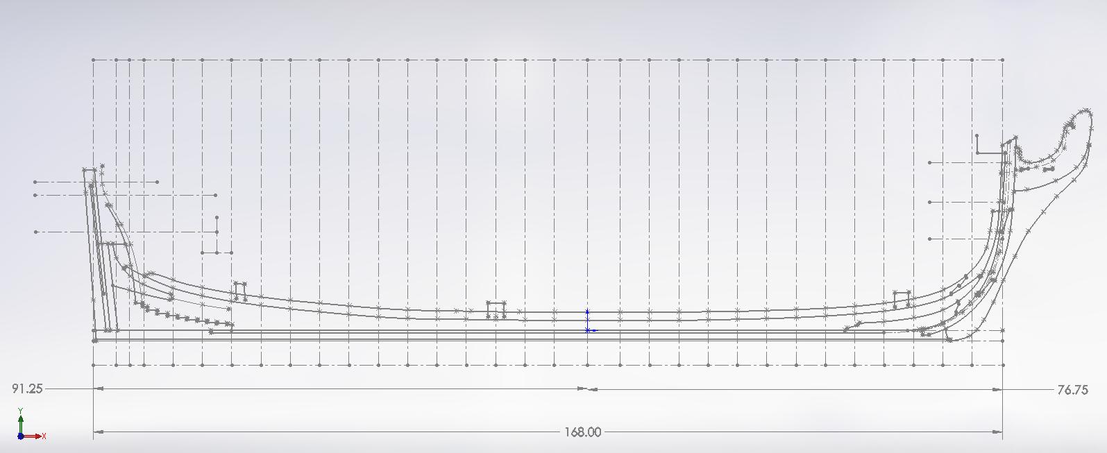
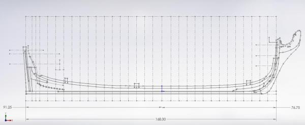
Below is the corrected model results. I've got the hull outline at the bow figured out and need to understand (draw) the same at the stern.
-
While making my corrections I found an error. I had an extra inch in the overall length and it took me days to realize the error. One dimension at the bow perpendicular was off. The node on the dimension leader is not connected to the line I had to zoom in to find it. Once corrected all the stars aligned perfectly
-
Regarding the additional annotations... I post the following with written permission of the author: I have taken a look at the contract in questions (ADT0009) and my conclusions are thus: a) The original contract was written for Bellerophon (1786). The amendments date from 1805 and are irrelevant to the above vessel. c) The amendments relate to building ships of the Fame class (1799) that had been ordered in 1805 - of which there were 4, possibly 5 (date of the latter is uncertain). The additional dimensions match the Fame class. I do not know why the Navy Office decided to reuse the contract as a specification for the Fame class, except that it may imply the Arrogant class and Fame class are more closely related than either David Lyon or Rif Winfield realised: the Arrogant class was designed by Slade and the Fame class by Henslow. For the purposes of the Bellerophon project the 1805 additions can be ignored. I hope that this makes sense. I have updated the Museum catalogue so it should go 'live' sometime. Yours sincerely, Jeremy Michell, MA Historic Photographs and Ships Plans Manager, National Maritime Museum
-
Bob What an invaluable piece of common sense info!!! I've been following this discussion as I have a hankering to pick up a lathe down the road but, like so many, it seems I don't have a clue. Thank you Alan
-
very good looking! (you know I am taking notes, right)
-
On another note my contact at NMM (Julie) just responded to my e-mail about the contract. Seems she was "out of the office" (vacation?) and forwarded my questions to the ships department. It will be interesting to learn what they believe the annotations were all about.
-
Just realized I hadn't posted the template fit on the hull Almost fits like a glove I believe this addition will make a huge difference
-
Close? ...............I can almost smell the wood! For some reason completing the hull has got me a little anxious but, like everything else, I'll eventually plough through it Not sure if I mentioned this before but I've always had to envision the part or assembly in my mind before I could draw it. The exciting part is I can now see all the timbers sitting on the keel and the cant frames curling into the posts. That is what excites me. Thank you and everyone else for following, the helpful comments and the words of encouragement (thank God for this forum, otherwise I'd likely be building a raft... and I'd get part of that wrong ) After having moved my stations I've noticed the sketch points for the stem and stern post and the keel need to be realigned as I had not yet anchored them. As I move them many seem to be falling into a more proper place now. Only half a zillion more to go. Alan
-
Got an extremely quick response from Chris Watton suggesting all the penned annotations may have been a suggestion to lengthen the ship during a refit in 1805 but the idea was not implemented. Considering it all history now. I've moved my stations in my model and presently little seems to have been affected. I will have to take some time to be sure, then clean up my keel, stem and stern post sketch, complete the hull and slice my timbers to make the templates. There is a light at the end of the tunnel
-
Thank you Alan for the suggestion I sent a PM to this gentleman and now get to practice the fine art of patience... something else I struggle with! On another note... I spent yesterday clearing out half the dungeon in preparation of expanding my play (work) room. Going to be more than doubling the size. Lumber, nails, drywall, screws, second door, hardware jamb kit, electrical plugs and boxes to be delivered this coming Saturday
-
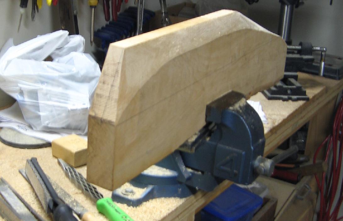
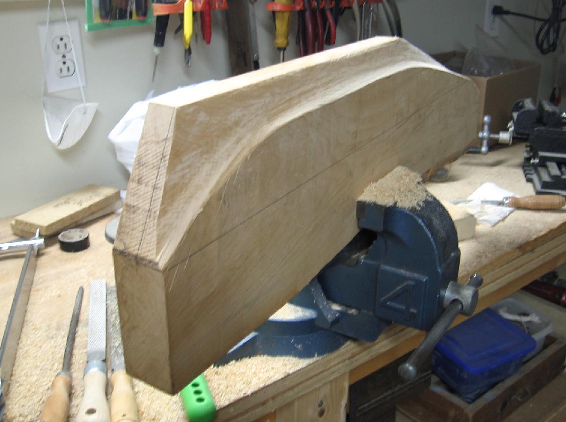
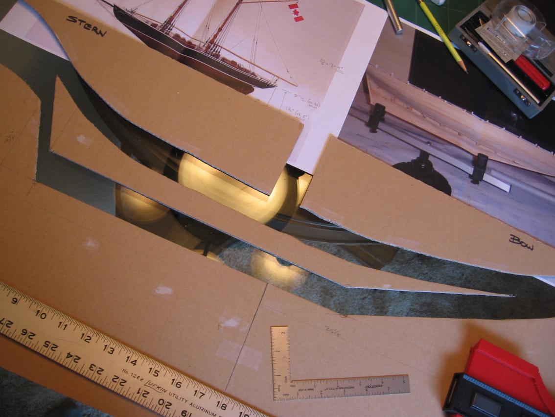
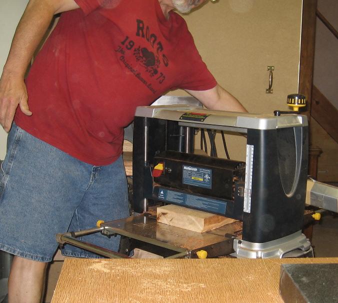
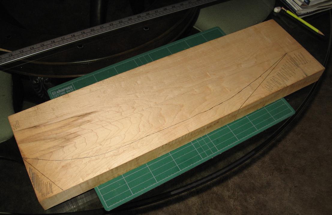
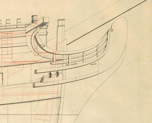
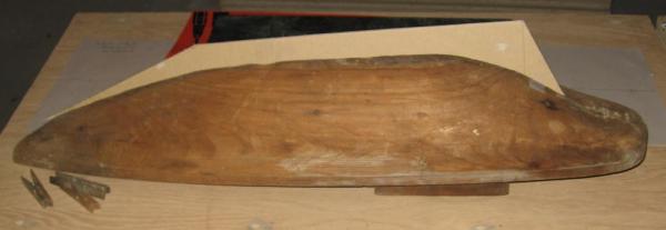
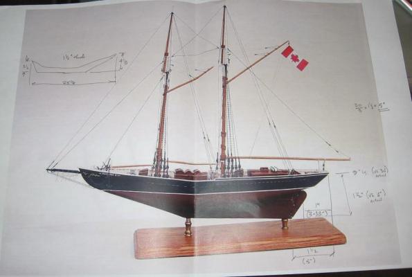
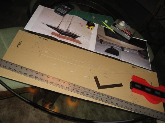
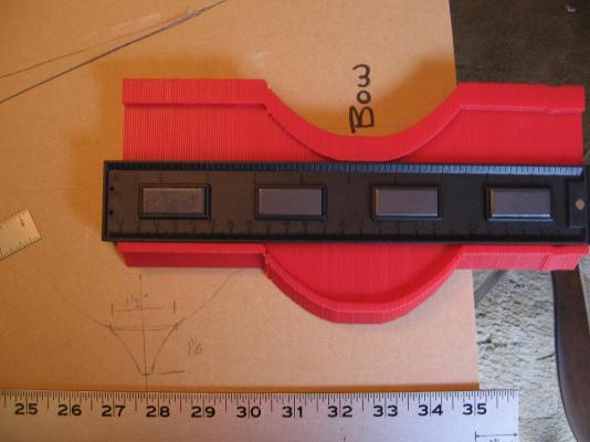
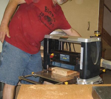
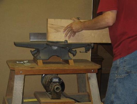
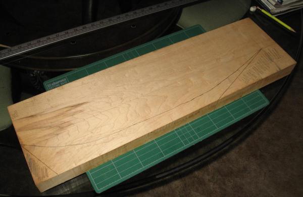
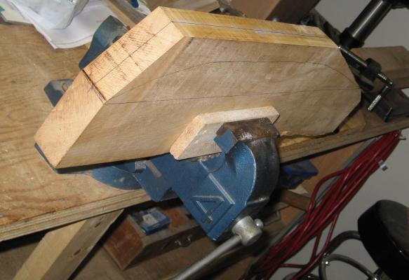
Yesterday was a rather rainy day in Niagara and so far I’m not sure today will be much better.... the flowers, grass and trees love it. Decided I needed to get going on this project as I could not get any yard work done. Earlier (see above) I took my tracing paper hull template and taped it to some stiff cardboard Now I traced the shape onto the cardboard with a soft (HB) pencil. I printed out a picture of the Bluenose from the forum for reference, measured the overall length, compared it to Charlie’s O/All Length and had my ratio to estimate dimensions After working out the dimensions of the skeg to be added to the underside I drew the shape onto the cardboard. Then cut out the template. I transferred the hull cross sectional shape to paper using my new (larger and brighter!) profile gauge and estimated the width of the skeg or piece of wood I would need to use (looks like 1-1/2 so I'll go with 1-3/4”). I went down to the dungeon and scoured through my scraps. Although I was ready to plane and glue and clamp two or three pieces together I found one piece of maple about 1-7/8” thick. I planed this down to 1-3/4” to create a flat surface. I then planed one edge. I then traced the template shape onto the block of wood, cut of the “ends” to shape with my band saw and now I am ready to shape with chisels and rasps I envision drilling two holes to glue and screw this to the hull. I will insert two dowels to hide the screws and use this as the mount similar to the model/ image I borrowed.

-
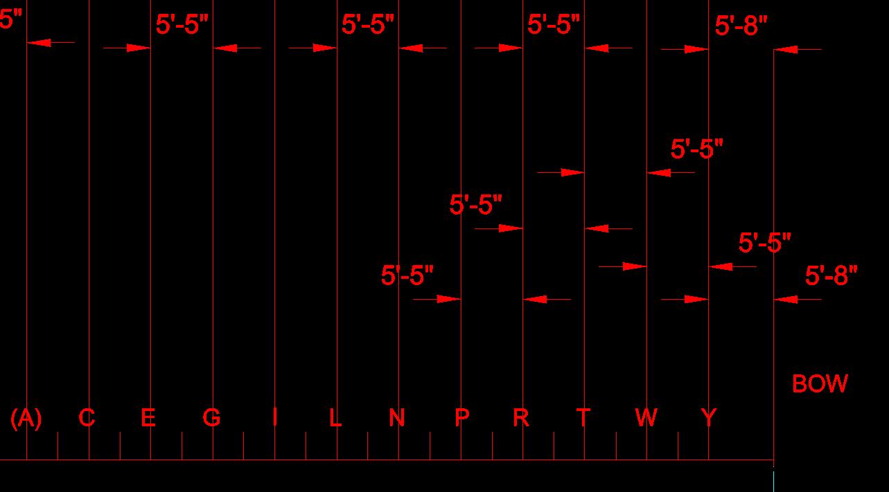
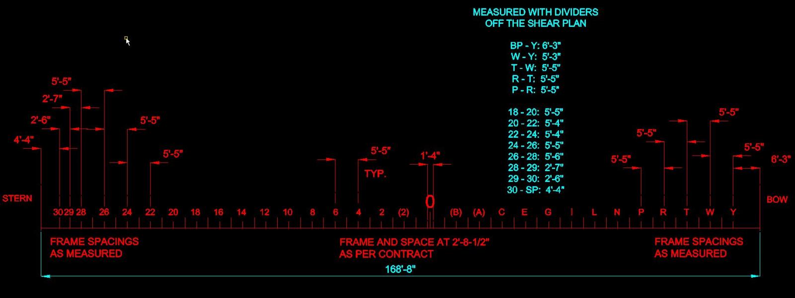
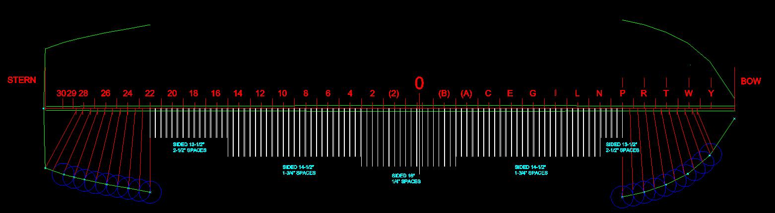
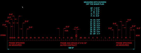
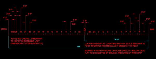
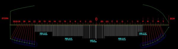
I’ve completed the sketch that nails down my station lines! My first sketch is a combination of double frame and space (2’-8-1/2” x 2 = 5’-5”) plus the spacing I measured to the bow and the stern perpendiculars. This left me with an overall length of 168’-8” which is 8 inches too long. My second sketch was after I noticed the bar scale on the plan read exactly 170 feet under the Bow Perpendicular. Having suddenly realized this I could read the nearest full dimension next to the dead flat position, draw the 1/12th divisions at the dead flat and measure with some degree of confidence the location of the dead flat. This meant whatever was left over at either end was “it”. Now I had my stations (reasonably) properly located. (I must keep reminding myself that I am not building a Swiss time piece!) My final sketch was to help me visualize the timbers, spacing (gaps) and cant frames. Now having a better visual understanding of this part I will be adjusting my model next week, get my hull completed and then, possibly, soon, begin making some templates for an actual build! Thanks goes to my NRG mentor whom I am certain must have been getting annoyed with my stubbornness. (I must keep reminding myself that it will not be full scale!)
-
How to build a wood case ?
AON replied to alexmd's topic in Painting, finishing and weathering products and techniques
you can also purchase extruded aluminium shapes that have the groove in them and use caulking to "glue" the plexiglas in the grooves trying to think outside the box! -
I should expand the explanation The (original TIFF and so) PDF images I was measuring off of are "stretched" (due to the original source) and so inaccurate as would be measuring off a (the) print. The lines on the PDF are a wee bit thick when I zoom in to measure so that probably doesn't help. My Solidworks model reflects these inaccuracies and so lines are manipulated If I were to trace off an imported image I get the same inaccuracies because the original image is stretched If I stretch the CAD tracing I would make from the image the curvature/straightness of the lines are compromised and require manipulation No matter what I do I've got to nudge things over and turn them about to make it look right and since I want to try to salvage what I've done to date .... My NRG mentor suggested measuring off the print with dividers and so I've given it a try It can't be any worse than what I've done so far and actually gives me repeatable dimensions where as the zooming in on the PDF to electronically measure rarely gives me the exact same dimension twice (a program tolerance issue) I am doing it all on a reference sketch in DraftSight because I need a "clean sheet" and my SolidWorks model is too distracting so I keep it closed for now. All will be transferred to the model once I get it straightened out.
-
links don't seem to work for me
-
Don, How so? (yes it is not recommended practice on the shop floor)
-
Good morning Druxey Your words about paper stretch from much earlier were very much on my mind when measuring. I attempted measuring directly below but the 1/12th divisions are not there Then I measured at the end nearest the station where the divisons are located Then I compared a few at the opposite end scale I was thinking I'd re-measure and draw out the bow and stern heights of breadth in 2D Draftsight off the half breadth, draw the cant frames and see how that compares for frame and space... then I can comfortable make a decision Alan
-
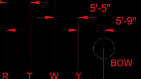
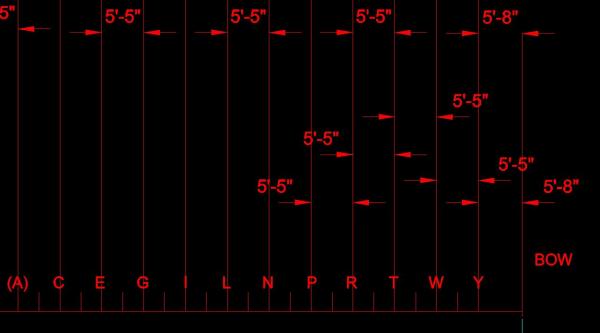
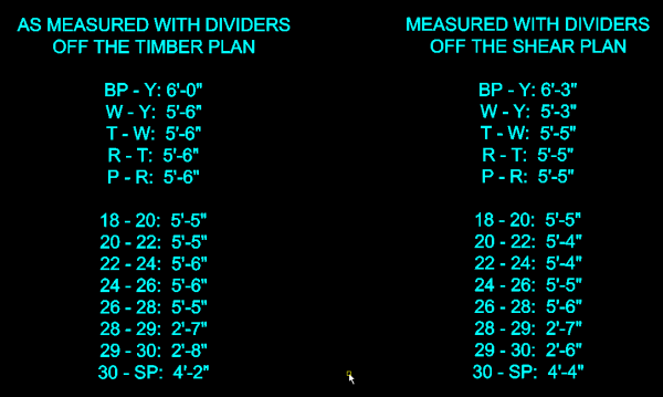
At the moment I am going to try to move forward at 168 feet long I need to make corrections to my station line locations My NRG mentor had mentioned measuring with dividers... so I did... off two different plans for comparison Here are the results It was admittedly easier than measuring off the PDF but could eventually result in a grazillion tiny holes on the plans Next I need to make it all add up to 168 feet. My NRG mentor told me the Room and Space dimension of 2'-8-1/2" is held from bow to stern when measured on the outside of the hull (or is that timbers) at the heights of breadth, not at the centre of the keel.... although okay to measure at the centre of the keel for the straight frames. I'll need to plot from my model this to double check. I am beginning to get more comfortable with accepting being close enough for the reduced scale as opposed to being dead nuts on accurate. This is a good thing ... right?
-
Druxey, That is what I originally thought... some ones thoughts scribbled on the contract. But there are so many other things ... the 1805 date for example. I usually love a puzzle and my darling wife (the super sleuth) has been doing what she does best ... looking for clues and finding additional info on the bankruptcy and the date of death for dear Mr. Edward Greaves. I e-mailed my contact at NMM this morning to ask for help deciphering the contract notations and hope I have better luck with a response then the poor fellow I had provided the contact info to for quotes on plans elsewhere on this site. I also asked my NRG mentor early yesterday and had not heard back from him as yet, I prefer to think he is working on it rather than him "having a life"! I need to learn the virtue of patience!
-
Good morning all. Thank you for the additional info and thoughts Mark. I was looking at the data I had printed out / collected from various source including Wikipedia (which I am told to take that particular info with a grain of salt) and very little agrees with each other. As for the NMM and their plans... it is my understanding that they still have stuff that is waiting to be reviewed, identified and catalogued so with my luck I am positive it will all come to light the day after I am done After one nights sleep on it I had another thought.... I wonder if there may be an "expert" at the NMM that can make sense of it all? Lord knows what strange things they've seen. As for the Billy Ruffian, as a 13 year old she (the sea cadet corps in Welland, Ontario, Canada) saved me. Also... If not for the sea cadet corps I would have never met the young girl that I now share my life with, my wife. I went through the ranks to eventually become Chief of the corps (cox'n) and then as an adult went further to be Officer Commanding the Corps for five years. Although as an old man I had no involvement for the last 20 years of her existence, it broke my heart (along with many other men and women) to see her shut down. This is my attachment to the name Bellerophon and why I am so keen on building this particular ship and not HMS Elephant for which I seem to have easily acquired all the info for.
-
Don (and all) The scribbling in the upper left corner of the first page of the document seems to read "Ships Contracted for 2h Jan 1805". I also see a very small 1805 scribbled above the heading "INTEREST" and below the eighth work payment during seasoning on the second to the last sheet. I am going to sleep on this for a short while and see if any sense of it comes in my dreams. Until then I'll ask again if anyone knows that they might spend 180% of the original cost to make her sea worthy and serviceable again after the Battle of Trafalgar. Would they actually make her 8 feet longer (how???) and about 9 inches wider (thicker boards on the hull???) Thinking back to the seasoning and launch delay... were the sums in the left column late payments due / made with interest? Since there was no war would the government be eager to hand out moneys, hence i wonder the cause of the gentleman's bankruptcy. (this doesn't make sense to me but it was a thought I had) I know there are quite a few forum members that are extremely knowledgeable (and talented) and hope one might shine a brighter light. More than willing to PM some select portions of sheets of the contract to study. Maybe I should post this problem elsewhere on this site so someone not visiting might see it... good idea. Will do that in the morning as might allotted play time is up for this evening. Mark: presently waiting the reprint of HMS Bellerophon (announced in the books section of the site) to arrive and wonder if it might reveal anything with regards to size. G'night world.
-
Thank you Mark According to the contract she did supply an income during the seasoning period. There were payments at regular intervals somewhat equal to the build payments