javajohn Posted December 2, 2022 Share #31 Posted December 2, 2022 Hi Ed, I'm new to the party here - I took a long break from modeling. I'm also building the Rattlesnake. Your build looks great! As you move on to the upper hull planking, my advice is really pay attention to the gun port framing, and the thickness of the bulkheads as you fair the inner portion. I didn't do that and ended up with gaps between the gunport frames and some of the planks. I have to go back and add filler to clean it up. John Keith Black and Dave_E 2 Quote John Current Build: Rattlesnake (Model Shipways 1:64) Link to comment Share on other sites More sharing options...
Ed Ku20 Posted December 2, 2022 Author Share #32 Posted December 2, 2022 Hi John, I've read through your build log a while back and took a lot of good information from it. I made notes from you and JPett about the inboard bulkhead fairing. I might not have picked up on that otherwise. Welcome to the party! Glad to have you aboard. Let me know when any other pearls of wisdom come to mind. I will be following your build as well. Looks like you are getting close to completing planking. Looks great! Thanks, Ed Dave_E and Keith Black 2 Quote Thanks & Best regards, Ed Kutay Current build: Model Shipways "Rattlesnake" Completed build: Model Shipways "Bluenose I" Link to comment Share on other sites More sharing options...
javajohn Posted December 3, 2022 Share #33 Posted December 3, 2022 Thanks Ed! I've only completed the first belt on both sides of the hull, so I've quite a way to go. I'm pretty slow at this. Keith Black and Dave_E 2 Quote John Current Build: Rattlesnake (Model Shipways 1:64) Link to comment Share on other sites More sharing options...
Ed Ku20 Posted December 4, 2022 Author Share #34 Posted December 4, 2022 OK Guys! I have a question for you all. My Transom Carving does not cover the top to bottom length of the laser cut transom. It is too short! With fear and trembling I managed to successfully pull the ends of the carving outward, using my hands, to fit the width of the the transom. I used a sanding stick to trim the edges to fit the carving. But, as I'm looking at the carving laying on the transom it's not tall enough!! Should I fit it at the top?? (Which is what I did when I was stretching it open) Then leave the bottom with just the wood? Or should I position it so it's even with the bottom of the transom and sand off the extra wood that shows at the top? Here are pictures showing these 2 options. I've never heard anyone complain about this fit. Has anyone else run into this? Option 1: Carving postioned at the top with wood showing below Option 2: Carving postioned flush with the bottom and extra wood at the top. Note the window openings are a little cramped like this. I would appreciate any input. Also, my windows are significantly smaller than the holes in the transom. I know this is a common problem. I saw one suggestion that if you are planking the transom, which I plan to do, over lap the hole a bit and set the windows against the planks. I think it would be difficult to get an even overlap of planking around each of these windows! Maybe some 1/32" trim on the outboard edges? What did you guys do? Thanks, Ed Keith Black 1 Quote Thanks & Best regards, Ed Kutay Current build: Model Shipways "Rattlesnake" Completed build: Model Shipways "Bluenose I" Link to comment Share on other sites More sharing options...
Gregory Posted December 4, 2022 Share #35 Posted December 4, 2022 11 minutes ago, Ed Ku20 said: Has anyone else run into this? Several Rattle builders have discussed this. Dave talked about it here: In the following posts, other builders talked about how they dealt with it. Dave_E, javajohn and Keith Black 3 Quote Luck is just another word for good preparation. —MICHAEL ROSE Current builds: Rattlesnake (Scratch From MS Plans On Hold: HMS Resolution ( AKA Ferrett ) In the Gallery: Yacht Mary, Gretel, French Cannon Link to comment Share on other sites More sharing options...
Dave_E Posted December 4, 2022 Share #36 Posted December 4, 2022 Hey Ed, I can show what I ended up with. Look at my log, I don’t want to get my build on your page. 👍 Keith Black 1 Quote Dave Current builds: Rattlesnake Completed builds: Lady Nelson On the shelf: NRG Half Hull Project, Various metal, plastic and paper models Link to comment Share on other sites More sharing options...
Oldsalt1950 Posted December 4, 2022 Share #37 Posted December 4, 2022 Ed, fit it to the top, and then cut a piece of wood to span the distance at the bottom, sort of a trim piece so to speak. Jim javajohn, Keith Black and Dave_E 3 Quote Current Build: Fair American - Model Shipways Awaiting Parts - Rattlesnake On the Shelf - English Pinnace 18Th Century Longboat I stand firmly against piracy! Link to comment Share on other sites More sharing options...
Ed Ku20 Posted December 5, 2022 Author Share #38 Posted December 5, 2022 Thanks Everyone for your replies. Dave, thanks for the additional pics. My transom actually matches the plan drawing pretty closely. I see that your transom carving reaches from the top to the bottom of the laser-cut transom. Mine simply comes up short! There's not enough metal!! Weird. Jim, thanks for your input. I am going to fit it to the top, as you recommended, and deal with the gap at the bottom. Not sure how. I've seen a couple of older builds, like Bill Campbell, where he just left the space blank. If I can carve a decent looking trim piece, I will use it. Otherwise, I may just leave the transom painted at the bottom. Stay tuned! Keith Black and Gregory 2 Quote Thanks & Best regards, Ed Kutay Current build: Model Shipways "Rattlesnake" Completed build: Model Shipways "Bluenose I" Link to comment Share on other sites More sharing options...
Dave_E Posted December 5, 2022 Share #39 Posted December 5, 2022 Hey Ed, Check out my post #93. After completing the bulkheads and making the transom carvings… that stern piece did not fit. I studied the drawings and came to the conclusion if I just put it in position, it would be way to low on the bottom. I goofed something or the drawings aren’t 100%. More than a couple of views on the drawings are “view” only and not to scale and that didn’t help me with the fitting problems. So I downsized the stern piece to fit, that’s why my Britannia seems to “fit”. So… when I get into one of these predicaments (it happened on my lady Nelson also), I do some engineering. When the ship is launched, only a fellow builder of this ship might notice a minute deviation from the drawing. If your stern wood fits per drawing, Jim’s suggestion is good. 👍 Keith Black, javajohn and Gregory 3 Quote Dave Current builds: Rattlesnake Completed builds: Lady Nelson On the shelf: NRG Half Hull Project, Various metal, plastic and paper models Link to comment Share on other sites More sharing options...
Ed Ku20 Posted December 5, 2022 Author Share #40 Posted December 5, 2022 1 hour ago, Dave_E said: More than a couple of views on the drawings are “view” only and not to scale Yes! I learned that with my Bluenose. You have to be really careful when looking at the blueprint plans. Some are to scale, some are "pictorial" only and others are double the scale to show detail better. I highlight those notes on my plans so I don't get them confused!! javajohn, Keith Black and Dave_E 3 Quote Thanks & Best regards, Ed Kutay Current build: Model Shipways "Rattlesnake" Completed build: Model Shipways "Bluenose I" Link to comment Share on other sites More sharing options...
Ed Ku20 Posted December 7, 2022 Author Share #41 Posted December 7, 2022 Stage B: Upper Hull – Planking & Deck Details Step 12: Knightheads & Timberheads I completed a couple of more steps with my Rattlesnake build by installing the Knightheads & Timberheads. From the plans it looks like these are about the size of a hull plank. I see that some builders use heavier pieces of stripwood to provide more support for the hull planks as they curve around the bow. I decided to follow this plan, but I don’t want to go too crazy. I kind of stumbled onto using the center posts leftover on the thick set for the bulkheads. Standing sideways the 3/32” depth is good with the lasercut Foc’sl railings. I cut 4 of these off and installed them. I used the Dremel with a cutting burr to draw the cut down the filler block at the right depth. Finished with files & sanding sticks to square up the hole. I’m going to wait until I’m ready to install the railing before gluing the pieces in place. I foresee some adjustments being required to line everything up. NOTE: I did not consider the fact that a cannon gunport needs to fit between bulkhead A and the knightheads. Fortunately, I unwittingly left enough room for this! I did use the blueprint plan and some dividers to space them out. I may leave these two gunports closed anyway. Step 13: Install Inboard & Outboard Transom Supports Next up is the Inboard & Outboard transom supports. These are provided as lasercut parts. My inboard supports were too short to reach the end of the counter block. I saw in someone’s Rattlesnake log they had the same issue and used a piece of scrap wood to extend the supports so they would fit. I'm not too shy to "borrow" a good idea! Everything got glued in place with Weldbond. I was afraid that the Outboard Supports just hanging from the edge of BHD M would be a bit flimsy. So, I decided to insert a piece of beveled stripwood on the inside to provide additional support. This also helped me to align the supports along the edge of the counter more easily. The bottom edge was sanded to match the angle of bhd M. I also beveled the top edge as indicated on the plans. Additional sanding was performed to get the transom to fit flush against the counter and the four supports. Also, smoothed the transition from the bottom edge of the supports into the sides of the counter block. I have not seen this anywhere, but I beveled under the notches to allow the transom to fit flush up to it. I’ve already started working on the transom and transom carving. It has been a real challenge to get everything to fit properly!! Thanks to my support team out there, I’m making progress now. Pictures to follow! ccoyle, Gregory, Prowler901 and 7 others 10 Quote Thanks & Best regards, Ed Kutay Current build: Model Shipways "Rattlesnake" Completed build: Model Shipways "Bluenose I" Link to comment Share on other sites More sharing options...
Dave_E Posted December 7, 2022 Share #42 Posted December 7, 2022 Looks good Ed! You are now a building resource of knowledge for those of us not as far along as you. Outstanding explanations of your process, thank you! 👍😀 Gregory, Ed Ku20, Keith Black and 2 others 4 1 Quote Dave Current builds: Rattlesnake Completed builds: Lady Nelson On the shelf: NRG Half Hull Project, Various metal, plastic and paper models Link to comment Share on other sites More sharing options...
Kenneth Powell Posted December 9, 2022 Share #43 Posted December 9, 2022 Moving right along and looking great. - Kenneth Dave_E, Ed Ku20 and Keith Black 2 1 Quote Link to comment Share on other sites More sharing options...
Ed Ku20 Posted December 13, 2022 Author Share #44 Posted December 13, 2022 (edited) Step 14: Prepare the Transom Step 15: Prepare the Transom Carving I completed a couple of more steps in my build process with the transom & transom carving. I worked on these simultaneously. First, I sanded the back of the transom to make it thinner before planking with 1/32 x 1/8” stripwood. I got it down to between 9/128 – 5/64”. I didn’t attempt to pre-bend it to wrap around the end of the Counter block. After adding the planks, windows and trim it would no longer bend!! But I used 6 rubber bands to hold it around a large pitcher! After ~24 hours it made a slight bend. The transom seems to be a place where modelers use their creativity. Mine is a blend of multiple ideas I liked from various builders, as well as my own. I used this color scheme: Black Transom; Yellow Ochre for window frames and a nameplate plaque that I made. Carving background & Trim wood is Ultramarine Blue. The scrollwork on the carving is Modelmakers Brass enamel. I use Vallejo acrylic paints everywhere else. After planking the transom, I painted it black. The Transom window frames were removed from Thickset F and the char sanded off. A quick test fit found them to be way too small! So, I cut some 1/32” square stripwood to insert as trim at the front of the window openings. I painted the trim with Yellow Ochre before gluing in place. I also painted the window frames. Cut pieces of plastic packaging to size to fit in the back of the window openings like glass. Used a touch of CA glue to sandwich the undersized window frames between the trim and the “glass”. Painted the back of the windows a Light Gray that I had left over from Bluenose. I decided it was simpler and pleasing, at least to my eye, to make all the windows instead of the dummy in the middle. Meanwhile, I was working on the transom carving. I did a lot of prep work before painting. I washed it in an ultrasonic jewelry bath (I actually do this with all the brittania metal). Then I polished it with the Dremel. I still did not like the overruns of metal all over the piece. So, I used a small carving burr in the Dremel and drilled out most of the excess metal. I think this turned out pretty well. I had planned to do a 2-step with acrylic paint over enamel and a rubbing alcohol wash to expose the scrollwork. I read about others doing it this way. I painted the entire piece with brass enamel. But then I decided to simply paint the blue background with a super fine brush under my magnifying glass/light. This worked quite well. I was able to wipe off any blue that got on the scrollwork with a damp dental swab! For the ship’s name, I really liked the way builder Dziadeczek used a sign board. I cut a 1/8” x 3/32” x 1.5” plank & painted it yellow ochre. I used clear laserjet decal paper w/ black lettering for the ship name. I applied 3 coats of Micro-Sol to help dissolve some of the decal material. I needed to do something with the empty gap below the transom carving. So, I painted a single wider molding strip at the bottom of the transom. Painted it Ultramarine Blue. The name plank was glued between this molding and the windows. This molding covers the space below the carving. Finally, inserted a pair of 1/32” molding strips between the name plank and the transom carving on either side. Used a rubber band to hold the finished piece in place to see what it looks like. I also installed the transom beam across the transom supports. I'm not sure when I’m going to actually attach the transom to the stern. Probably just before planking the bulwarks or when it becomes necessary to continue with the upper hull. Next step is to install the waterway. Edited December 13, 2022 by Ed Ku20 Removed extra picture javajohn, Paul Le Wol, DARIVS ARCHITECTVS and 9 others 11 1 Quote Thanks & Best regards, Ed Kutay Current build: Model Shipways "Rattlesnake" Completed build: Model Shipways "Bluenose I" Link to comment Share on other sites More sharing options...
Dave_E Posted December 14, 2022 Share #45 Posted December 14, 2022 REAL NICE Ed! Your setting the bar pretty high. 👍😀 Keith Black 1 Quote Dave Current builds: Rattlesnake Completed builds: Lady Nelson On the shelf: NRG Half Hull Project, Various metal, plastic and paper models Link to comment Share on other sites More sharing options...
Oldsalt1950 Posted December 14, 2022 Share #46 Posted December 14, 2022 Excellent work on the transom. Jim Dave_E and Keith Black 2 Quote Current Build: Fair American - Model Shipways Awaiting Parts - Rattlesnake On the Shelf - English Pinnace 18Th Century Longboat I stand firmly against piracy! Link to comment Share on other sites More sharing options...
javajohn Posted December 14, 2022 Share #47 Posted December 14, 2022 Very nice work, Ed. I think the addition of the trim was a great idea, and I really like the color scheme. Keith Black and Dave_E 2 Quote John Current Build: Rattlesnake (Model Shipways 1:64) Link to comment Share on other sites More sharing options...
Ed Ku20 Posted December 14, 2022 Author Share #48 Posted December 14, 2022 Thanks a lot guys! Means a lot coming from all of you. I'm just trying to hold my own in this company of outstanding shipwrights! Hey, I've got some questions or perhaps confirmation about which stripwood to use for planking in various locations. I've tried measuring the width off the blueprint plans, but these do not match any of the wood supplied in the kit. When I look at pictures of Rattlesnakes on this forum some of the planks look wider. Based on the large number of wood strips provided for 3 of the bundles (48, 50 & 50) I'm thinking as follows: 1.) Bulwarks - inboard ceiling & outboard above the wale use WP3603 1/32 x 3/32" 2.) Lower Hull - use WP3622 1/16 x 3/16" 3.) Deck Planks - use WP3620 1/16 x 1/8" Has anyone figured this out? I think I'm going to lay the Wale strake early before installing the gunport frames to provide a visual position for the sheer of the deck. Appreciate any feedback others might have. Thanks! Ed Dave_E and Keith Black 2 Quote Thanks & Best regards, Ed Kutay Current build: Model Shipways "Rattlesnake" Completed build: Model Shipways "Bluenose I" Link to comment Share on other sites More sharing options...
Dave_E Posted December 14, 2022 Share #49 Posted December 14, 2022 I’m waiting for this answer as well! 😉 Keith Black 1 Quote Dave Current builds: Rattlesnake Completed builds: Lady Nelson On the shelf: NRG Half Hull Project, Various metal, plastic and paper models Link to comment Share on other sites More sharing options...
Oldsalt1950 Posted December 14, 2022 Share #50 Posted December 14, 2022 Ed, the planking sounds correct. I'd then install the waterway, and take measurements from there, as it is a fixed position aligned with the sheer of the deck. Add the gunport framing and then attach the Wale strakes. Take your time. Jim Keith Black and Dave_E 2 Quote Current Build: Fair American - Model Shipways Awaiting Parts - Rattlesnake On the Shelf - English Pinnace 18Th Century Longboat I stand firmly against piracy! Link to comment Share on other sites More sharing options...
Dave_E Posted December 14, 2022 Share #51 Posted December 14, 2022 Thanks Jim! 😀 Keith Black 1 Quote Dave Current builds: Rattlesnake Completed builds: Lady Nelson On the shelf: NRG Half Hull Project, Various metal, plastic and paper models Link to comment Share on other sites More sharing options...
Oldsalt1950 Posted December 15, 2022 Share #52 Posted December 15, 2022 (edited) No problem guys. You will have to decide how you are handling the waterway where it meets the cabin bulkhead. Jim Edited December 15, 2022 by Oldsalt1950 Keith Black and Dave_E 2 Quote Current Build: Fair American - Model Shipways Awaiting Parts - Rattlesnake On the Shelf - English Pinnace 18Th Century Longboat I stand firmly against piracy! Link to comment Share on other sites More sharing options...
Ed Ku20 Posted December 15, 2022 Author Share #53 Posted December 15, 2022 Thanks Jim! I just put in the waterways yesterday. Per your advice, next up will be the waterways then! Keith Black and Dave_E 2 Quote Thanks & Best regards, Ed Kutay Current build: Model Shipways "Rattlesnake" Completed build: Model Shipways "Bluenose I" Link to comment Share on other sites More sharing options...
Oldsalt1950 Posted December 15, 2022 Share #54 Posted December 15, 2022 If you have the waterways in, I'd be working on the gun ports. after that the Wales and exterior planking above the Wales. Jim Dave_E and Keith Black 2 Quote Current Build: Fair American - Model Shipways Awaiting Parts - Rattlesnake On the Shelf - English Pinnace 18Th Century Longboat I stand firmly against piracy! Link to comment Share on other sites More sharing options...
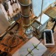
Ed Ku20 Posted December 15, 2022 Author Share #55 Posted December 15, 2022 30 minutes ago, Oldsalt1950 said: If you have the waterways in, I'd be working on the gun ports. after that the Wales and exterior planking above the Wales. Oops! Sorry about that! Yes, I meant to say gun ports. 1 hour ago, Oldsalt1950 said: You will have to decide how you are handling the waterway where it meets the cabin bulkhead. Dave_E, this is for your information. Here's how I handled the waterways, as Jim is talking about. I'm assuming that the deck area will not be visible past the cabin bulkhead wall or at the bow, forward of BHD "A". Here are a few pictures of what I recently completed. Here is the waterway after soaking for a couple of hours in water to soften it up. I clipped it in place overnight and then glued it the next morning. After gluing in place That 1/8" square strip wood was impossible to bend at the point of the bow! I soaked it for 2 hours and could not get that end to budge without possibly breaking. So, I cut it off at A and glued it at the bow so there is someplace to butt deck planks up against. IF I need to plank that far forward. At the cabin wall, I ran the waterway just past BHD "I". I will decide if it looks better to build the cabin wall around the waterway or cut it off flush there. This way I have the option. But, I will not be taking it all the way back through the cabin. Started working on the gun port and oar port frames. I built a jig that I hope helps with this process. I'll let you know how it goes. I still need to build 1 cannon and some temporary deck planking to test the positioning of the portholes. Thanks, Ed Paul Le Wol, Dave_E, Prowler901 and 3 others 6 Quote Thanks & Best regards, Ed Kutay Current build: Model Shipways "Rattlesnake" Completed build: Model Shipways "Bluenose I" Link to comment Share on other sites More sharing options...
Dave_E Posted December 15, 2022 Share #56 Posted December 15, 2022 Did you try heat on that wet wood, it will bend like a pretzel. Gregory and Keith Black 2 Quote Dave Current builds: Rattlesnake Completed builds: Lady Nelson On the shelf: NRG Half Hull Project, Various metal, plastic and paper models Link to comment Share on other sites More sharing options...
javajohn Posted December 15, 2022 Share #57 Posted December 15, 2022 (edited) Jim gives some great advice here about the order of work. I did not follow that order, installing the gun ports before the waterway. So, my measurements were a bit off. Pay close attention to the height of the port framing above the waterway! Edited December 15, 2022 by javajohn Keith Black 1 Quote John Current Build: Rattlesnake (Model Shipways 1:64) Link to comment Share on other sites More sharing options...
Ed Ku20 Posted December 15, 2022 Author Share #58 Posted December 15, 2022 8 hours ago, Dave_E said: Did you try heat on that wet wood, it will bend like a pretzel. Dave, what do you use to heat it? I used hot water to start with. But it had cooled off by the time I used the wood. Keith Black 1 Quote Thanks & Best regards, Ed Kutay Current build: Model Shipways "Rattlesnake" Completed build: Model Shipways "Bluenose I" Link to comment Share on other sites More sharing options...
Oldsalt1950 Posted December 15, 2022 Share #59 Posted December 15, 2022 Ed, are you going to just try bending a piece to fit from the stem to the frame after it? I thought about that waterway long and hard 1/8x1/8 is not easy to bend that sharp. It would be easier to make a laminated waterway out of 1/32 x 1/8 wood, assembling each ply of the laminate after it is bent. You can then sand the profile and glue it in place. Much less frustrating, just takes a little more time. Jim Keith Black 1 Quote Current Build: Fair American - Model Shipways Awaiting Parts - Rattlesnake On the Shelf - English Pinnace 18Th Century Longboat I stand firmly against piracy! Link to comment Share on other sites More sharing options...
Dave_E Posted December 15, 2022 Share #60 Posted December 15, 2022 Hey Ed, I have an old airplane iron, and my wife gave me a couple spare hair curling irons (smooth type). When I’m bending my guitar sides, I soak the wood pretty good and then it goes into a heated bending jig. For the water ways I will be using one of the curling irons… bend and check, bend and check. When it’s time to start any planking… search the forum for instructions on plank bending. Make yourself a jig and get a small travel iron or the like. Don’t even need to wet the wood! I don’t want to hijack your thread and turn it into plank bending, but I know of 4 different ways to do planking. If you search the build logs, you’ll see all of them. Decide on what you like and go for it. However…. I’m here to tell you the dry heat bending does work pretty slick. Look at Glenn Barlows work. Keith Black and Ed Ku20 2 Quote Dave Current builds: Rattlesnake Completed builds: Lady Nelson On the shelf: NRG Half Hull Project, Various metal, plastic and paper models Link to comment Share on other sites More sharing options...

Recommended Posts
Join the conversation
You can post now and register later. If you have an account, sign in now to post with your account.