Ed Ku20 Posted December 15, 2022 Author Share #61 Posted December 15, 2022 Jim, I'm actually planning to just leave it the way it is. I figure the end of the bow will be hidden under the forecastle deck. I was thinking ahead to when I will need to bend the hull planks around that sharp turn at the transom. Might need to use Dave's technique for applying heat to the wet wood. Dave_E and Keith Black 2 Quote Thanks & Best regards, Ed Kutay Current build: Model Shipways "Rattlesnake" Completed build: Model Shipways "Bluenose I" Link to comment Share on other sites More sharing options...
Ed Ku20 Posted January 5, 2023 Author Share #62 Posted January 5, 2023 Step 17: Install Gunport Framing & Oar Sweep Holes The next step in my build process is to install the gunport frames. As with most things on this model, I did a lot of studying before I started this step. Here are some notes I made. Maybe they will be of value to someone else who is building a Rattlesnake! NOTE-1: Use 1/16” square strip wood for the gunport & oar sweep portholes. Make it flush with the outboard edge. After planking the outer gunwales, the inboard BHD wood needs to be reduced in thickness down to 1/16” to be flush with the frames. On the outboard side they must be “faired” to match the vertical curve of the hull. NOTE-2: Per Chuck Passaro, the sides of the portholes should be parallel to the BHD's and the top and bottom should be parallel to the deck! I found this to be very difficult to achieve! Per Russ, gunports must follow the deck line, at a consistent height above the deck in order for the cannons to fit properly. (I did do these 2 things.) The gunports follow the sheer (longitudinal curve) of the deck, which is not the same as the sheer of the hull! NOTE-3: Per JSGerson, even gunports that have closed lids need a frame constructed around the opening. Post #29. I gave up trying to get the frames to fit between the Quarter Deck BHD’s. The vertical curve and deck sheer combined required too much twisting and my little 1/16” square frames fell apart. I do not plan on putting cannons here. I will figure out how to make the lids fit properly after the wale planking is done. Maybe make a lip inside the lid to fit in the hole? Or can I just glue them to the hull without cutting out the hole? I will see what looks best. I plan to build my own gunport lids when the time comes! 1. Preparation work a. Make a Jig – I used Scott Larkins’ Post #45 to make a jig for a consistent size to the frames. Based the jig on measurements taken from the plans. I put some scotch tape down in the space between the jig sides to prevent glue from sticking to the jig. This jig worked great, but restricted the ability to make the sides parallel to the BHD’s because they were perfect squares. I focused on getting the bottom edge to flow with the top of the waterway. b. Build 1 cannon -- used as a test to center the barrel through each gunport frame. I ordered replacement cannons and carriages from Syren Ship Model Co. These are slightly taller than the ones in the kit and pushed the top of the frame a little closer to the main rail. Hope this isn’t a future problem! I spent 10 hours just building that first little cannon! Still need to add rings and rigging later on down the road. c. Make a small section of deck planking to stand the cannon on top of the BHD’s The Gunport Frame making jig Assembling the Syren cannon. BTW, these are really beautifully made. I learned a few things that will help me make the rest of them even better when the time comes. Shaped this tiny "Quoin" handle with Dremel and files 2. Make the frames – I measured the distance between the bulkheads with my caliper. Cut the top & bottom frame pieces to match this width. Insert into the jig. Cut the vertical sides using the jig post to get the right length (see step 3 below). Measure the distance from the right side of the frame to the BHD & mark this distance on the top frame. Use the jig post to position the two vertical frames and apply PVA glue. Be sure to remove the post before the glue sets!! I added vertical posts at the ends for strength and to provide more surface for gluing to the BHD. 3. Cut a pile of vertical posts – these are all the same size, so may as well make a bunch at one time. I taped down a wood strip in my razor saw miter box to match the length needed. Actually, made slightly larger and sanded them to fit. 4. Set-up the Oar port – Take measurements from the plan. Used a 1/8” square piece of stripwood as a jig to make the oar port. Cut scrap wood and glue in place the correct distance from the cannon gunport. Put a small piece of scrap wood above and below the hole. 5. Glue the frames to the BHD’s – Adjust the frames to the sheer of the deck. Do this by lightly sanding the ends so the frame can fit btw bhd’s to match the sheer of the waterway. This was only marginally successful. Use PVA glue once all are fitted. I started on the starboard side and made all the frames first, then glued them in place. By the time I got to the port side, I built them in the jig & immediately glued them as I went down the hull. Making the frames in the jig Starboard side ready to install on the ship Pictures of the completed frames Step 18: Paint frames & waterways red I first installed the “cover boards” on the quarter deck. This took a bit longer than expected. I ended up having to add a few more shims on top of the quarter deck to smooth out some dips along the edges. Then hand brushed using the red hull paint leftover from Bluenose. I looked at some other red colors, but liked this one the best. As I was installing the last frame on the port side, I discovered that the waterway was noticeably higher at the quarter deck (bulkhead I). The port side of the bhd is higher than the starboard, which raised the waterway up. I loosened the glue & cut off the waterway on an angle. Then sanded the wood down until the 2 sides were even. This area will be hidden behind the cabin wall, so it should not be noticeable. Current views of the Rattlesnake Sorry, for the long-winded post. There was a lot going on with these couple of steps! Next step is the wale and bulwark planking. I have a few questions about that, but will use a separate post. Thanks, Ed wool132, CODY, Knocklouder and 10 others 12 1 Quote Thanks & Best regards, Ed Kutay Current build: Model Shipways "Rattlesnake" Completed build: Model Shipways "Bluenose I" Link to comment Share on other sites More sharing options...
Oldsalt1950 Posted January 5, 2023 Share #63 Posted January 5, 2023 Nice work Ed. While thinking about the wale and bulkhead planking, also think about the cabin/quarterdeck bulkhead and how you are going to approach that. Jim Keith Black and Dave_E 2 Quote Current Build: Fair American - Model Shipways Awaiting Parts - Rattlesnake On the Shelf - English Pinnace 18Th Century Longboat I stand firmly against piracy! Link to comment Share on other sites More sharing options...
Ed Ku20 Posted January 7, 2023 Author Share #64 Posted January 7, 2023 Thanks Guys for all the positive feedback! It is much appreciated. Jim, I will start studying that cabin bulkhead. Is there something specific I need to be aware of? Do any of you use a block plane for tapering your planks? I used the Exacto knife and a straight edge with my last ship. That was very tedious. But I did not have to do much tapering for Bluenose. I bought a little 3" Buck Bros block plane at Home Depot and tried some practice cuts with it. I'm not getting acceptable results! I sharpened it on my stone and have the blade edge sticking out as little as possible. But, no matter which direction I plane it just chatters and chews the wood. Occaisionally I get a decent shaving. Either the equipment I'm using is too cheap or the operator is doing it wrong! I know you have to plane with the grain, but it doesn't seem to matter which direction I push. Would appreciate any tips or techniques you guys use. I looked at that video of the guy for Modelers Central. It looks easy as pie when he does it!! Thanks, Ed Dave_E and Keith Black 2 Quote Thanks & Best regards, Ed Kutay Current build: Model Shipways "Rattlesnake" Completed build: Model Shipways "Bluenose I" Link to comment Share on other sites More sharing options...
Oldsalt1950 Posted January 7, 2023 Share #65 Posted January 7, 2023 Ed, it all depends on how you approach constructing it. It looks like you left a little space after the end of the waterways at the bulkhead frame which means you won't have to try and cut the very bottom corners to fit around the waterway. The part you really need to think about is the windows in the panels. Will you actually cut them out, or just paint them in. Jim Keith Black and Dave_E 2 Quote Current Build: Fair American - Model Shipways Awaiting Parts - Rattlesnake On the Shelf - English Pinnace 18Th Century Longboat I stand firmly against piracy! Link to comment Share on other sites More sharing options...
wool132 Posted January 8, 2023 Share #66 Posted January 8, 2023 16 hours ago, Ed Ku20 said: I'm not getting acceptable results! I found a video from five years ago by a guy who had no luck trying to tune his Buck. The good news is that there were a couple of comments from folks who were able to get it to work well: Beavis Christ: "Try flipping the blade so that the bevel is facing down. I set mine up that way, and it works wonderfully. When setting it up, I put it on a piece of glass, or any totally flat surface, and put a piece of paper just under the front of the block, let the blade drop down and sit flat against the glass, and tighten the screw." Robbie Vigil: "(Put) Sand paper between the blade and holder and put the bevel down and it's good to go." Another suggested trying a replacement blade (about $10 bucks) from Lee Valley. I use this miniature block plane ($45) from Lee Valley to taper my planks. No tuning required. Highly recommended. Jonathan Dave_E and Keith Black 2 Quote Current Build: Zulu - Lady Isabella Completed Builds: Lowell GB Dory, Norwegian Pram, Lowell GB Dory Redux, Bounty Launch, Nisha, Lady Eleanor - Fifie On the Shelf: Ranger, Erycina, HMS Alert, etc, etc. Hibernating: Gunboat Philadelphia, Bluenose In a Time Vault Due to Open in 2025: Syren Link to comment Share on other sites More sharing options...
javajohn Posted January 8, 2023 Share #67 Posted January 8, 2023 I second @wool132's recommendation of the Veritas miniature block plane. I just got one a few weeks ago to help with planking and it works flawlessly. I was using a sanding block before that and was not happy with the results. I did spend time sharpening and honing the blade before starting to use it. I hope you can tune the Buck Bros plane to work as well. A plane is a real timesaver. My Rattlesnake kit came with very poor-quality strips with rough edges that really need to be planed. Some were not even usable for their intended purpose, because once smoothed they were too narrow. John Dave_E 1 Quote John Current Build: Rattlesnake (Model Shipways 1:64) Link to comment Share on other sites More sharing options...
Ed Ku20 Posted January 8, 2023 Author Share #68 Posted January 8, 2023 1 hour ago, wool132 said: I use this miniature block plane ($45) from Lee Valley to taper my planks. No tuning required. Highly recommended. Hi Jonathan, thanks for the recommendation. I was just checking out this plane. It looks like it is much better to fine tune than the one I have now, with 1 thumbscrew! I think I will make the investment! 11 minutes ago, javajohn said: I hope you can tune the Buck Bros plane to work as well. John, I don't think I have the patience to make this thing work! I should have purchased a better tool from the start. I like the sound of "works flawlessly". Dave_E, Knocklouder, Keith Black and 1 other 4 Quote Thanks & Best regards, Ed Kutay Current build: Model Shipways "Rattlesnake" Completed build: Model Shipways "Bluenose I" Link to comment Share on other sites More sharing options...
Ed Ku20 Posted January 13, 2023 Author Share #69 Posted January 13, 2023 (edited) Hey John and Jonathan, I wanted to let you know that I received my Veritas miniature block plane from Lee Valley late yesterday. Spent some time working today to get the Wale strake installed on the starboard side. The Veritas plane was amazing! I cut two planks to length and clamped them together in my hobby vise. That little plane cut through the two boards together like a sharp knife through butter! I was surprised how small it was. But it is perfect for tapering planks. Here are a couple of pictures to let you see how I did. I'm going to make a full posting of this entire step once I'm finished with it. Thanks for the recommendation. I'm looking forward to planking now!!! Ed Here's my newest tool in the arsenal. You can see how small it is compared to a penny! Small but mighty! No problem tapering these 2 Wale planks simultaneously Glue is drying on the starboard wale strake. Yes, I did install one continuous plank to help align everything else above and below it more easily. Tomorrow the port side goes in. Edited January 13, 2023 by Ed Ku20 Correct spelling error Keith Black, ccoyle, wool132 and 7 others 10 Quote Thanks & Best regards, Ed Kutay Current build: Model Shipways "Rattlesnake" Completed build: Model Shipways "Bluenose I" Link to comment Share on other sites More sharing options...
Ed Ku20 Posted January 21, 2023 Author Share #70 Posted January 21, 2023 Step 19: Plank the Counter Step 20: Install the Wale Strake Step 21: Install Focsl & Qtr Deck Breast Beams In my previous post I showed the work on the Wale in conjunction with my struggles to taper these planks using the cheap block plane I purchased at a big box store. Finally got that solved with help from Jonathan (wool32) & John (javajohn). I completed a few more steps, so I want to circle back and submit a post on the process for my steps 19, 20 & 21. The Wale is made from a 1/16” x 3/16” stripwood plank (part #3622). The bulwark planks above it are 1/32” x 3/32” stripwood planks (3603). The measurements from the kit blueprint plan matched up to the side of my model to indicate that the top edge of the Wale should fall about even with the bottom edge of the Waterway. I tried to make a “tick strip” with a piece of the stiff card stock to mark on the bulkheads. (This didn’t work very well. It ended up being significantly longer than the available space on my ship!) I finally just eye-balled the position with the waterway and marked the bhd’s with a pencil. I decided to make the wale out of a single piece of stripwood to ensure that it is straight and level along this line. Here are the construction steps I used. Step 19: Plank the Counter – The first thing I did was plank the Counter block at the stern with 1/32” x 3/32” stripwood. I squared off the outer edges with a sanding stick. Planks above the wale run straight across the outside of the counter. Eventually I will sand the 2 edges into a miter-like cut. Counter Planking Step 21: Install Focsl & Qtr Deck Breast Beams While I was waiting for my new block plane, I installed the Focsl & Qtr Deck Breast Beams 1. 3/32” x 3/16” pieces of stripwood are required. The focsl beam is supposed to sit on a pair of support beams between bulkheads C & D. My gunport frames are higher than normal because of the replacement cannons, so I ended up setting the beam right on top of the frames. 2. Sand the open edge of each beam to make a rounded edge 3. The beam needs to be bent to match the curve of the focsl deck camber. I remember reading in other logs that you should keep the laser cutouts from the bhd’s. I’m glad I did! I soaked the beams; rubber banded them to the top of their respective cutouts (C & I) and let them dry out overnight to the correct camber. 4. Glued them in position the next day Focsl Deck Breast Beam behind Bulkhead C Quarter Deck Breast Beam in front of Bulkhead I Step 20: Install the Wale Strake 1. Once I received my new block plane, I tapered both wale planks (see pics in above post #69) 2. Dry fit the wales on the ship. Word of caution on two points: a. I assumed that the full width of the wale plank would match the plans around bhd’s G & H. The plank on the plan is 1/32” narrower than 3/16” full size of the actual kit wood. Either a different size of wood was used back then or they tapered the entire plank. I saw no reason not to use the full width and adjusted the tapers at the bow & stern to be a consistent percentage of the difference. b. I made a bend in the bow end of the wale so that it followed the upward curve of the waterway. After I installed the wales on both sides, I did not like the way this was looking. So, I unglued this area and dropped it down to make a gentler curve. I hope this wasn’t a mistake, but it seemed that’s what the wood was telling me to do! A little less edge bending. 3. Steps for Installing the Wale a. These planks are quite a bit heavier than the planks I used on Bluenose (which were the same as the Snake’s deck planks). I needed to soak them longer (about 15 minutes) to get them pliable enough to bend to the curve at the bow. I use a 2-foot-long PVC pipe that is capped at the bottom for soaking a full-length plank. b. I took Dave_E’s advice and “borrowed” a thick diameter curling iron from my wife to make the curve. Dave, it worked great!! Clamped them in position until they dried to the proper shape. c. Remove the clamps; apply PVA (I use Gorilla Glue); re-clamp in position until dry Wale installed on the port side of the ship 4. Glue in the Timberheads and Knightheads – I made the cutouts in the filler block and the timber pieces earlier. To glue or not to glue them now, that was a question. I test fit the laser-cut covering board. It looks like I will need to edge bend the aft ends of the covering boards into the ship to make them fit on the focsl deck beams correctly. I decided I needed to glue the timberheads & knightheads in position now. I used the covering boards to align them underneath. I am going to wait until I’m done with the upper hull planking before finally gluing in the covering boards. This will make it easier to adjust the 1/32” overhang. I already started planking the bulwark above the wale. I will save that for my next post. Gregory, CODY, ccoyle and 8 others 11 Quote Thanks & Best regards, Ed Kutay Current build: Model Shipways "Rattlesnake" Completed build: Model Shipways "Bluenose I" Link to comment Share on other sites More sharing options...
Ed Ku20 Posted February 6, 2023 Author Share #71 Posted February 6, 2023 (edited) Quick question for the Rattlesnake team. When do you recommend installing the Q-Deck and Gun Deck railings? Before or after completing the lower hull planking? I'm almost done with the upper bulwark planking both outboard & inboard. The Focs'l stanchions and railings are definitely going in after as they are much more fragile! Thanks! Ed Edited February 6, 2023 by Ed Ku20 Add more info Keith Black and Dave_E 2 Quote Thanks & Best regards, Ed Kutay Current build: Model Shipways "Rattlesnake" Completed build: Model Shipways "Bluenose I" Link to comment Share on other sites More sharing options...
javajohn Posted February 7, 2023 Share #72 Posted February 7, 2023 Hi Ed, I planked the bulwarks before adding the cap rails and covering boards. My thought process was that it would be easier to paint the bulwarks without having to mask or repaint the cap rails. I'm waiting to install the railings and knightheads until after the hull planking is complete. I'm pretty rough with the model and knew I'd break those rails off during planking. I've already snapped the beams several times due to my clumsiness! I'm looking forward to seeing your work on the bulwarks! John Dave_E, Keith Black, Gregory and 1 other 4 Quote John Current Build: Rattlesnake (Model Shipways 1:64) Link to comment Share on other sites More sharing options...
Ed Ku20 Posted February 8, 2023 Author Share #73 Posted February 8, 2023 11 hours ago, javajohn said: I planked the bulwarks before adding the cap rails and covering boards. Hi John, Thanks for your answer to my question. So, your order was - plank upper bulwarks, install the railings (except on the Focs'l), then paint, then plank the lower hull. I will post my work on the upper hull planking very soon. I spent some time studying the pictures of your railings. I'm having trouble wrapping my head around the first few planks at the quarter deck. The ones just above the strake that gets the "molding strip". I think I made my beam too wide. It seems like it will be in the way of the short vertical rail that drops down from the Q-Deck to the gundeck. I have a picture of this below. I cut it to fit to the outside of the bulkhead extension. Should I cut the beam back on each side? I think I need to cut it back to where ceiling planks will sit on the red waterway. The vertical piece of railing needs to be at least as wide as the planked bulkhead, correct? Then stop the next outside plank so it's even with the forward edge of that BHD extension and continue planking the same way all the way up. I'm afraid to cut that beam! How did you get that short piece of rail to curve with the BHD extension? Thanks! Ed BTW, your Rattlesnake is looking really awesome! Looks like you will keep the upper bulwarks on the quarter deck yellow ochre. I've seen some guys paint it black and others ochre. Still deciding for mine! Dave_E and Keith Black 2 Quote Thanks & Best regards, Ed Kutay Current build: Model Shipways "Rattlesnake" Completed build: Model Shipways "Bluenose I" Link to comment Share on other sites More sharing options...
javajohn Posted February 11, 2023 Share #74 Posted February 11, 2023 Hi Ed, Thanks for the compliments! Yes, I think you need to cut the beam back. I am not sure I built mine correctly, but I made the beam end at the inner edge of the bulkhead extension. The waterway extends over the beam, but I am not sure that is correct. I've seen models done either way. I found it difficult to make sense of the plans in this area. The vertical cap on the bulkhead extension does indeed need to be wide enough to cover the edges of the inner and outer planks. You don't need to bend it to get a curve; just put on a strip piece that is wide enough to cover the edges of the planks. Then sand or cut it so it is flush with the planks. Cutting away the beam can be intimidating, but it's wood and you can cover up your mistakes with small pieces, filler and paint. I read somewhere on the site that a ship model is just a bunch of mistakes that have been covered up! John Dave_E and Keith Black 2 Quote John Current Build: Rattlesnake (Model Shipways 1:64) Link to comment Share on other sites More sharing options...
Ed Ku20 Posted February 13, 2023 Author Share #75 Posted February 13, 2023 On 2/11/2023 at 9:02 AM, javajohn said: I found it difficult to make sense of the plans in this area. On 2/11/2023 at 9:02 AM, javajohn said: I read somewhere on the site that a ship model is just a bunch of mistakes that have been covered up! Exactly Right! I too had difficulty making sense of the blueprint plans for this area! He does not provide any view of this part of the railing showing the beam, waterway and railing in place, much less the qtr deck planks! I did cut the beam back. I will find out how I did when I get to planking the deck! That's still a ways off. Hopefully we help one another minimize the number of mistakes we need to cover up!! I'm finally ready to post my upper hull & ceiling planking. Should be posted soon Thanks John! Keith Black and Dave_E 2 Quote Thanks & Best regards, Ed Kutay Current build: Model Shipways "Rattlesnake" Completed build: Model Shipways "Bluenose I" Link to comment Share on other sites More sharing options...
Ed Ku20 Posted February 13, 2023 Author Share #76 Posted February 13, 2023 (edited) Step 22: Plank the Outboard Bulwarks above the Wale Step 23: Plank the Inboard Bulwark with “Ceiling Planks” Hello Everyone, It’s taken me some time to get to the point where I’m ready to post some progress. Doing the planking above the Wale has been a slow process. I’ve been moving slowly and spending a lot of time trying to understand the blueprint plans and how everything fits together. Taking my time and trying to do it right! The instruction manual outlines several rules for planking. For the most part I followed these rules. Before starting to plank I made a diagram showing the way I wanted to stagger the butt joints for each strake. I broke the strakes into 3 planks each. Pic of the “Planking Rules” and the bundle of 1/32” x 3/32” stripwood from the kit (WP-3603) I worked on the outboard and inboard planking simultaneously. I started on the hull side, beginning at the wale and working up to the rails. I alternated adding a full strake on the port side and then the same on the starboard. This is recommended to make sure things don’t get out of alignment. For the outboard planks at the bow, I measured the length of plank required for that position and soaked it in a glass jar for about 5 to 8 minutes. Then I used a curling iron I “borrowed” from my wife to bend the plank to fit the curve of the bow. Be sure to apply glue to the top of the entire lower plank below to hold the bottom edge of the new plank above it. Here is my process. Soaking a plank in a jar of water for bending to fit the bow Bending the front end of the plank with the curling iron Clamping the damp plank in place to dry fit it to the shape of the bow Applying glue to the top of the last plank before setting the next one in place Plank clamped while the glue sets The completed plank after glue is set and clamps removed First 3 strakes on starboard side at the quarter deck area 4 strakes completed; view at midship area. Another plank on the starboard side with glue setting After planking halfway up the outboard side, as measured at the midship gundeck area, I switched to the inboard ceiling planks. I thought this would make it easier to get my fingers inside the deck area and allow me to see what I’m doing. Before starting on the ceiling planks, I sanded down the inboard side of the bulkheads to 1/16” as called for on the plans. This was done for the gundeck and focsl. It did not appear to be required on the quarter deck. I just sanded to even them out. I alternated back and forth between inboard and outboard once I got to the gunports & oar ports. I used full length pieces of stripwood on the inside. I planked over the holes both in & outside. I cut the holes out on each side after completing each strake of planks. I used an Exacto knife equipped with a saw blade to do the cutting. When finished, the edges were cleaned up with jewelry files. Ceiling planks on the port side showing the cutout gun & oar port holes The last strake at the top of the gundeck was done in 2 sections instead of 3 I have a number of spots where my clamps pushed the plank too tightly and formed a “sunken” spot. These 1/32” boards are very pliable. I will fix these later with sanding and filler, where needed. I found it helpful to glue some extra 1/16” thick supports between the bulkheads in various spots as I approached the top of the hull. This was especially necessary for the top couple of strakes where the bulkhead extensions were like short nubs! These provided more surface area for gluing. The final (top) strake that runs the full length of the hull will get a molding strip installed over the top of it. This will be done later after sanding and installing the railings. Pic showing extra supports along the bulwarks, between the BHD extensions The next step is the quarter deck planking. The next plank is the first one that stops at the end of the q-deck. Actually, it goes a about an inch farther to form a step to the gundeck rail. Next there is a plank that gets the “Covering Board” strip installed over the top of it. Finally, there are 5 more planks to reach the top of the quarter deck. My plan here is to glue the gunport lids directly to the hull. Therefore, no holes in q-deck area. Pic showing 3 planks installed on the outboard quarter deck & ceiling planks being installed Top strake that gets the molding strip and also the step-down plank from the quarter deck I left some over-lap at the front and back of the quarter deck planks for trimming and sanding later The last step for this subject is the last couple of planks at the focsl. I added a couple of extra supports for gluing. I soaked these planks and used the curling iron for the curve at the bow. Here are some pics of the completed work. I still have to do some sanding and filling before painting anything. Pics of completed planking at the focsl, port & starboard sides Most current pics of completed planking around the ship I’m a little worried about the next step. I am going to install the laser-cut covering boards on the Focsl. Dry fitting shows that they do not fit too well! I have an idea for how to make them fit. I’ll let you know if it works!! Thanks, Ed Edited February 14, 2023 by Ed Ku20 Removed extra pictures javajohn, Prowler901, DARIVS ARCHITECTVS and 4 others 7 Quote Thanks & Best regards, Ed Kutay Current build: Model Shipways "Rattlesnake" Completed build: Model Shipways "Bluenose I" Link to comment Share on other sites More sharing options...
allanyed Posted February 14, 2023 Share #77 Posted February 14, 2023 On 1/5/2023 at 3:58 PM, Ed Ku20 said: Assembling the Syren cannon. BTW, these are really beautifully made. I agree Syren makes beautiful things, including the carriages. It is hard to tell from the photo but the brackets look like they are parallel rather than angled as in the drawing below. From Volume 2 of The History of English Sea Ordnance, by Adrian Caruana, page 373. There are a number of other examples in the book as well. Allan DARIVS ARCHITECTVS, Keith Black and Dave_E 3 Quote PLEASE take 30 SECONDS and sign up for the epic Nelson/Trafalgar project if you would like to see it made into a TV series. Click on http://trafalgar.tv There is no cost other than the 30 seconds of your time. THANK YOU Link to comment Share on other sites More sharing options...
Ed Ku20 Posted February 14, 2023 Author Share #78 Posted February 14, 2023 1 hour ago, allanyed said: It is hard to tell from the photo but the brackets look like they are parallel rather than angled as in the drawing below. Allan, it is hard to see even in this picture, but the carriage is definitely built to be wider in the back. There is an angle created by using a shorter axel in the front. Look at the additional space at the sides of the cannon where you can see the rear axel. The trucks (wheels) in the front are also larger then the back, as in your photo. DARIVS ARCHITECTVS, ccoyle, Dave_E and 2 others 5 Quote Thanks & Best regards, Ed Kutay Current build: Model Shipways "Rattlesnake" Completed build: Model Shipways "Bluenose I" Link to comment Share on other sites More sharing options...
Ed Ku20 Posted February 14, 2023 Author Share #79 Posted February 14, 2023 Hi Guys, I've got one more post to complete the steps on the upper deck, at least for now. I told you I had an idea how to get the laser-cut Focsl Covering Board to fit. Well I'm happy to report this worked! I soaked the 2 pieces for the covering board for a good 10 or 15 minutes. While that was preping, I turned the ship upside down on a piece of thin cardboard and traced the outline of the bow/focsl on the cardboard. I placed the cardboard on a piece of cork board. When the covering boards were pliable, I used pushpins to hold them in place inside of the outline I traced. I let this dry overnight. This afternoon I was able to glue them in place on top of the focsl with only minimal adjusting! I am very pleased with the end result! I still have a few steps left. Sanding and wood fill, install the railings, prime and paint the areas that will be red. I'm going to wait until the lower hull is planked before doing these steps. I don't want to damage anything while working on the ship upside down. I expect progress will slow down a bit while I'm planking. Here are a couple of pics of the focsl covering board. Thanks, Ed Prowler901, Kenneth Powell, DARIVS ARCHITECTVS and 5 others 8 Quote Thanks & Best regards, Ed Kutay Current build: Model Shipways "Rattlesnake" Completed build: Model Shipways "Bluenose I" Link to comment Share on other sites More sharing options...
Ed Ku20 Posted March 25, 2023 Author Share #80 Posted March 25, 2023 (edited) Stage C Lower Hull – Planking Hull Planking & Painting Step 25: Planking the Lower Hull As requested by Dave_E, I am posting my current progress. According to my master plan, I am starting on Stage C. Step 25 is Planking the Lower Hull. I spent a lot of time struggling to wrap my brain around how this step is supposed to go! I studied the pictures posted on every Rattlesnake build log to see how the planks are supposed to lay over the bulkhead frames and especially the bow and stern blocks. I watched You Tube videos on planking. But I have to visualize things on my model. I wasn’t getting the visual I needed from looking at the build log pictures. The videos, were helpful with techniques. I found some useful info from Ken Bascom’s tutorials. My plan was to start with the Garboard Strake. Then move ‘down’ the hull installing Belt C. Then move to Belt A. Lastly, fill the middle space with Belt B. I planned on using 3 planks per strake on each side of the hull. I still wasn’t comfortable, but decided to just start working and see what happens! I decided not to install any battens to start out. Garboard Strakes – I used a 1/16 x ¼” wood strip. This Garboard is not supposed to be tapered or cut. Run it straight along the keel. Only sand it to match the shape at the bow without any upward turn. This installed without any problems. Below: Garboard strake on starboard side Looking down on both Garboard planks Plank 1 (next to garboard) – Like the garboard, this plank is not tapered. Run it straight across on top of the garboard and shape at the bow without turning upward. Use the standard stripwood, 1/16” x 3/16” (part #3622). I sanded the lower edge to get a flush fit with the garboard. No butt joints were used. Below: Plank #1 being added A Pause and New Plan! At this point I took a pause. I needed to figure out how I was going to proceed. From now on the plan was to divide each strake into 3 planks per side. I also needed to figure out how I was going to determine the amount of tapering to do on the rest of the planks. I measured the distance between Plank #1 and the Wale at each bulkhead, plus the bow and stern. I needed to figure out how many full width planks will be needed at BHD G, the widest point. I did not trust that the measurements off the plans would match my model! I had to visualize it on my ship! So, I cut short pieces of planking that would cover 3 bulkheads. Using some rubber bands around the hull, I laid down planks in the empty space between plank #1 and the Wale along either side of BHD G. I came up with 11 full width planks required. I made a spreadsheet and determined the plank width required at each bulkhead, the bow & stern. This revealed that tapering is only required at the bow. Most of the planks will work fine at full width. And the stern might need an extra stealer, because it could be wider than 11 planks. I decided I did not need to use battens. I drew lines on each bulkhead using my test planks to show where each one fits. My new plan is to alternate between the top and bottom of the hull laying down planks. I will check my measurements as I go and adjust the amount of tapering to match the remaining gap. Plank 2 – On the next strake I used 3 planks per side. The bow now had to be tapered. I love the Veritas block plane. It makes tapering a snap. Unfortunately, I made 3 mistakes at this point. a. I did not realize it at the time, but I extended the tapered length for this plank at the bow to be longer on the starboard side versus the port. I only now realized that this messed up my calculations and will leave this side a strake less at the starboard bow! More on the solution to this problem later. b. The butt joint at bhd K had all the edge bending tension and caused a bulge. I thought about how to fix this for a while and considered inserting a stealer. This seemed too scarry to attempt! So before installing strake #3, I drew a straight line connecting the smooth parts at the bottom of the strake on either side of the bulge. I cut the bulge out with an Exacto knife. This also reduced the amount of edge bending occurring at the stern for future strakes. I also decided to use only 2 planks per strake from now on. It’s too difficult to hold the plank flat and bend at a joint. c. But the worst problem I had was this...I was pushing on the plank to force it to stay in position and I snapped the deck side of the keel where the two keel clamps were holding the ship upside down!! I also crushed a couple of the deck supports in the process. I thought I was going to cry! I managed to glue Humpty back together again. But, I’m afraid to attach the keel clamp again for planking. I went back to my old school pre keel clamp. I cut up a wine bottle cardboard shipping insert to fit the Rattlesnake's shape and strapped it down. It’s actually working fine. Below: Installing Strake #2 Strake #12 & 11 – Next, I decided to jump “down” and work on the strake just below the wale. I wanted to see how the planks will run into the transom. OMG, the bend & twist around the stern filler block into the transom is a bear! I’m developing whole new techniques to soak and bend wood at a 90-degree angle with a curling iron!! Every plank must be cut, soaked, bent, soaked and bent some more, wet fit and clamped to the hull until dry. I messed up the first one, but I’ve made some good plank bends since. It takes me about 3 days to complete each strake (port & starboard). That brings you up to date. I’ve completed the Garboard and the 3 strakes next to it and 2 strakes under the wale. I’ll need to do some filling and sanding when done, but I hope you guys think it looks pretty good so far. Here are the last pictures taken today. Below: Dry-fitting strake #3 Current progress as of today: FYI, to solve the issue with the starboard side with plank #2 I decided to increase the tapering at the bow end to fit the missing plank. The planks from bhd D to the stern should not be affected. Hopefully, once everything is sanded and painted no one will know the difference. Thanks, Ed Edited March 25, 2023 by Ed Ku20 Remove smiley face! Prowler901, Dave_E, javajohn and 3 others 6 Quote Thanks & Best regards, Ed Kutay Current build: Model Shipways "Rattlesnake" Completed build: Model Shipways "Bluenose I" Link to comment Share on other sites More sharing options...
javajohn Posted March 26, 2023 Share #81 Posted March 26, 2023 She's looking good Ed! Those twists and bends are indeed a bear! Sanding a painting will make all the difference. In my build log, I posted some before-after pictures of the hull sanding. Ed Ku20 and Dave_E 1 1 Quote John Current Build: Rattlesnake (Model Shipways 1:64) Link to comment Share on other sites More sharing options...
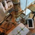
Ed Ku20 Posted April 5, 2023 Author Share #82 Posted April 5, 2023 Well boys, I just had a major problem!! I snapped the stem off the bow while trying to bend a plank in place. I'm not sure how to fix this. I'm afraid just gluing it back on will not provide enough reinforcement. I thought about inserting some dowels (small nails or pegs of wood) in the stem piece and trying to align them up with the keel. Does anyone have any suggestions? I hope I haven't wrecked my entire model!! Here's a picture of the damage. I've had some concerns about how thin that line of wood is along the rabbet. It's hard to be aware of that when you are pressing against the ship trying to hold stuff in place! I would appreciate any ideas on how to repair this. Thanks, Ed Quote Thanks & Best regards, Ed Kutay Current build: Model Shipways "Rattlesnake" Completed build: Model Shipways "Bluenose I" Link to comment Share on other sites More sharing options...
Ed Ku20 Posted April 5, 2023 Author Share #83 Posted April 5, 2023 Hi Gregory, Thanks for the tip. I'm always afraid to click on those delete buttons. I've read you can wipe out your entire log with one wrong click! My one concern about using dowels is lining up the dowel in part A with the hole in part B. The alignment on this piece will need to be very precise. Any suggestions on a technique for doing that would be appreciated. Thank You! Ed Dave_E 1 Quote Thanks & Best regards, Ed Kutay Current build: Model Shipways "Rattlesnake" Completed build: Model Shipways "Bluenose I" Link to comment Share on other sites More sharing options...
Ed Ku20 Posted April 6, 2023 Author Share #84 Posted April 6, 2023 Gregory, I was able to delete the post without any issues! Thanks Your approach on the repair sounds like a good plan. I am going to work on it. I'll let you know how it turns out. Thanks, Ed Gregory 1 Quote Thanks & Best regards, Ed Kutay Current build: Model Shipways "Rattlesnake" Completed build: Model Shipways "Bluenose I" Link to comment Share on other sites More sharing options...
Altduck Posted April 6, 2023 Share #85 Posted April 6, 2023 23 hours ago, Ed Ku20 said: My one concern about using dowels is lining up the dowel in part A with the hole in part B. The alignment on this piece will need to be very precise. Any suggestions on a technique for doing that would be appreciated. Just a thought from someone who's never tried it, but could you use steel pins (cut off brads), drill the holes a tad oversized, and use epoxy to fill the gaps and give you some wiggle time to align the pieces before it sets up? Dave_E and Kenneth Powell 2 Quote Richard Link to comment Share on other sites More sharing options...
Woodshipguy Posted April 7, 2023 Share #86 Posted April 7, 2023 On 10/25/2022 at 12:15 PM, allanyed said: This has been mentioned in other posts so I hope you don't mind it being brought up here as it maybe something to consider for the future. The Fully Framed Model Volume I, page 142 goes into detail on the taper of the knee of the head as the Swan class ships tapered 60% in width, so pretty noticeable, rather than the knee being grooved to accommodate the figure head legs. This tapering practice was common on most, if not all, British ships of war, but maybe ships built in New England did not follow this tapering practice. Allan on the stem taper does it taper all the way down to the keel?? Dave_E 1 Quote Link to comment Share on other sites More sharing options...
Kenneth Powell Posted April 7, 2023 Share #87 Posted April 7, 2023 Ed - The same thing happened to me. I used a finishing nail just long enough to reach and hold the piece in place. I predrilled a very small hole and ground off the head and used liberal amounts of glue. After driving and counter sinking the nail, I clamped and rubber banded everything together and checked alignment. It was a very nervous time. Those deck beams on the bulkheads are also fragile. I think I popped 3 of them. - Kenneth Dave_E and Ed Ku20 2 Quote Link to comment Share on other sites More sharing options...
Ed Ku20 Posted April 7, 2023 Author Share #88 Posted April 7, 2023 Hi All, So, I've managed to put Humpty back together again! I could not find a suitable sized dowel to use for the repair. I ended up doing as Richard suggested. I used a long thin finishing nail (less than 1/16 (7/128) x 1 inch long). I put the stem piece on the drill press and drilled out a hole that was a snug fit for the nail. Due to the width and shape of the stem, I felt I could only safely put no more than one nail through it. I positioned the piece and started driving the nail a very short way into the keel just to start a hole there. Removed the stem piece and applied a coating of Weldbond on both sides. Then I repositioned the stem and drove the nail all the way into the keel. I had widened the hole slightly at the top so I could countersink the nail head. I did not cut off the nail head so it would hold securely without adding any glue into the hole. Below are a couple of pics. I still need to do some filling and sanding, but I think it turned out pretty well. It seems very secure. I just have to be much more careful not to press against the side of the stem. Just 4 more strakes left to finish the hull planking! Time to get back to work! Below you can see the countersunk nail head in the repaired part. Above the repaired section you can see one of the original nails I used. This held secure when I broke it! Guess I should have used 2 from the start? 12 hours ago, Woodshipguy said: on the stem taper does it taper all the way down to the keel?? Answering Woodshipguy...I did do a slight taper on the stem all the way to the keel. I mostly just removed the squared off edges. Thank You Gregory and Richard for your support! It was much appreciated in my time of crisis!! Altduck, Gregory, Dave_E and 3 others 6 Quote Thanks & Best regards, Ed Kutay Current build: Model Shipways "Rattlesnake" Completed build: Model Shipways "Bluenose I" Link to comment Share on other sites More sharing options...
Gregory Posted April 7, 2023 Share #89 Posted April 7, 2023 That really looks good! Dave_E and Ed Ku20 2 Quote Luck is just another word for good preparation. —MICHAEL ROSE Current builds: Rattlesnake (Scratch From MS Plans On Hold: HMS Resolution ( AKA Ferrett ) In the Gallery: Yacht Mary, Gretel, French Cannon Link to comment Share on other sites More sharing options...
allanyed Posted April 7, 2023 Share #90 Posted April 7, 2023 (edited) On 4/6/2023 at 9:32 PM, Woodshipguy said: on the stem taper does it taper all the way down to the keel?? In a word, yes it does get wider as you move downward. Picture and a thousand words, &c. It is based on a drawing in Volume I of TFFM by David Antscherl. The dimensions shown are from Steel's Elements and Practice of Naval Architecture for a British 24. Allan Edited April 8, 2023 by allanyed DARIVS ARCHITECTVS and Dave_E 1 1 Quote PLEASE take 30 SECONDS and sign up for the epic Nelson/Trafalgar project if you would like to see it made into a TV series. Click on http://trafalgar.tv There is no cost other than the 30 seconds of your time. THANK YOU Link to comment Share on other sites More sharing options...

Recommended Posts
Join the conversation
You can post now and register later. If you have an account, sign in now to post with your account.