Woodshipguy Posted April 8, 2023 Share #91 Posted April 8, 2023 1 hour ago, allanyed said: In a word, yes it does get wider as you move downward. Picture and a thousand words, &c. The dimensions shown are for a British 24 circa 1800. Allan thank you for that i understand now i appreciate it Dave_E 1 Quote Link to comment Share on other sites More sharing options...
javajohn Posted April 8, 2023 Share #92 Posted April 8, 2023 That's an excellent repair job, Ed! Mine broke too, but I was more fortunate in that it only cracked at the rabbet line, so I was able to glue it without using pins. Breaking keels and beams seems to be the norm for the rattlesnake! Dave_E 1 Quote John Current Build: Rattlesnake (Model Shipways 1:64) Link to comment Share on other sites More sharing options...
Ed Ku20 Posted April 15, 2023 Author Share #93 Posted April 15, 2023 On 4/8/2023 at 8:14 AM, javajohn said: Breaking keels and beams seems to be the norm for the rattlesnake! You are absolutely correct! I just broke another deck beam yesterday! I tell myself to be more careful, but you don't even realize you are putting pressure on a sensitive spot when the ship is upside down for planking. I even reinforced my beams early on. Oh well, I'm getting good at repairing the damage I cause! Dave_E 1 Quote Thanks & Best regards, Ed Kutay Current build: Model Shipways "Rattlesnake" Completed build: Model Shipways "Bluenose I" Link to comment Share on other sites More sharing options...
Ed Ku20 Posted May 1, 2023 Author Share #94 Posted May 1, 2023 Hello Fellow Shipwrights, I've reached a major milestone on my build... planking on the lower hull has been completed. This step took me 100 hours and 72 calendar days. I found this hull to be difficult to plank! But, I learned a couple of things along the journey. I've already documented some of my difficulties! Here are a couple more lessons learned. Lesson #1. In my infinite wisdom (NOT!) I decided I didn't need to use battens to separate the hull into 3 sections, as per the instructions. In retrospect, I think that battens would have helped me avoid the issue I had with laying the planks in straighter lines and getting the same number of planks on both the port and starboard sides. I ended up with not enough space for the plank width at the bow and too much space at the stern. I solved this by custom carving and installing a jigsaw shaped piece to fill the leftover space on each side. And then inserting some narrow pointed planks at the bow, to have enough strakes to cover the stern. I think when the hull is painted and finished it will look fine. But, I took a shortcut that I will avoid on my next build. Someday I would love to build a ship without using paint. Just natural wood and varnish! Lesson #2. I think I should not have installed the extra filler block between bulkheads A & B. Or, at least they were not shaped properly. This caused me problems getting an even flow around that curve at the bow. I ended up with some "stairsteps" going on with my planking at the bow, because I could not get the planks to touch the entire surface of the block. That and I also had some severe edge bending due to the lack of a straight line caused by issue #1. This made it difficult to get the plank to lay flat against the hull on the "shorter" side (the edge facing the keel). At this point I've done some initial sanding to clean up the rough spots. I still need to do some filling and more sanding. I like to use Tamiya white putty to fill holes and smooth out the hull surface. It give a smoother surface than wood putty. After that, I need to repair damage I caused to two deck supports and the port side of the focsl covering board. Totally crushed that!! Here are some pics of the completed planking. Far from perfect, but I think I can work with this! Dave_E, Oldsalt1950, Kenneth Powell and 4 others 7 Quote Thanks & Best regards, Ed Kutay Current build: Model Shipways "Rattlesnake" Completed build: Model Shipways "Bluenose I" Link to comment Share on other sites More sharing options...
Kenneth Powell Posted May 1, 2023 Share #95 Posted May 1, 2023 Ed - Excellent milestone. Your planking really looks good. Sanding too smooth with remove all the beauty marks from a planked wooden ship. Just an opinion. - Kenneth Dave_E 1 Quote Link to comment Share on other sites More sharing options...
Ed Ku20 Posted May 1, 2023 Author Share #96 Posted May 1, 2023 So Kenneth, is your point that those beauty marks don't need to be sanded away completely. Leave some marks for character? Thanks, Ed Gregory and Dave_E 2 Quote Thanks & Best regards, Ed Kutay Current build: Model Shipways "Rattlesnake" Completed build: Model Shipways "Bluenose I" Link to comment Share on other sites More sharing options...
Kenneth Powell Posted May 1, 2023 Share #97 Posted May 1, 2023 Ed - Yes, that's my point. That's the way I did it, but no one has to follow along. Please see page 1 of my Rattlesnake build log to see how it turned out. I did use a very small amount of filler and sanded, but not to the point of being really slick. I kind of like the wooden ship character. Of course, it's your model and please finish it to your own liking. Hobbies allow us to express ourselves. One person's humble opinion - Kenneth Ed Ku20 and Dave_E 1 1 Quote Link to comment Share on other sites More sharing options...
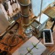
Ed Ku20 Posted June 11, 2023 Author Share #98 Posted June 11, 2023 (edited) Stage C Hull – Miscellaneous Pieces & Painting Step 31: Add Anchor rope holes & anchor bumper pads, Chesstree, Kevels & Sheaves to hull I gave some thought to the order of the steps for the various tasks and pieces that need to be added to the hull at this time. I ended up changing things around from my original spreadsheet. When I took into consideration how some of these pieces needed to fit in between the molding & covering strips, I made adjustments. The Chesstree will be installed after the railings and moldings are finished. The Kevels will be dropped down to when the deck is finished. These are on the inboard side of the bulwarks. Step 26: Drill holes for Mounting the ship – it is important to drill the holes for the brass mounting posts now. It is much more difficult to turn the ship over once other parts are installed. I drilled holes using the pin vise gradually increasing in size until I got the proper diameter hole. The hole size needs to be small enough to allow the threads on the screws to bite into the wood for a strong fit. Step 31a: Anchor Pad – use ¼” x 1/16” piece of stripwood. This piece fits between the focsl covering board & the wale. I had to soak and bend the bottom half of the board with the big curling iron to fit the curvature of the hull. I clamped it in place and allowed it to dry fit to the hull before gluing. After the dry fit, I was able to glue the board in position with just my fingers holding it in place for a short time. Step 31b: Anchor Rope holes – these are made from 2 overlapping pieces of stripwood 1/32” x 3/16”. This assembly sits above the Wale and butts against the stem. The longer/bottom board, by my measurement is about 9/16” long. The shorter/top board is 15/32” long. First, I shaped the rounded edges on the outboard side before gluing the 2 pieces on top of one another. Then I beveled the inboard side for a close fit up to the stem. In order to pre-fit the pieces to the bow curvature, I soaked the assembled wood pieces and rubber banded them to a glass jar that matched the curve of the bow. I let this dry overnight. The pieces were glued to the hull. The holes for the anchor rope were drilled with the pine vise parallel to the center line of the ship. The rope holes go thru both boards and the upper bulwark of the hull. NOTE: This hole needs to be outboard of the head rail that will attach just inboard from it. Step 31c: Sheaves – there are 8 sheaves positioned around the upper hull. They fit in holes drilled through the bulwarks. Rigging ropes pass through the wooden sheave and over a pulley inside the sheave. They are tied off on a cleat or belaying pin on the inboard side of the bulwark. I could not find any build log that showed how to make these. Dimitry Markov had some good pictures in his Snake log. But, no “how-to”. Therefore, I am going to post a “How-to” on how I made my sheaves. Hopefully someone will find it useful! I do not have any special knowledge and limited skill. But, I’m willing to share my experience with a first-time attempt at something new! FYI, this required a lot of trial, error and scrap generated! The tricky thing with the sheaves is they can have a lot of detail in a very tiny piece. It looks like most builders just drill a hole through a rectangular piece of wood. But I remember something Dave (CPDDET) told me. “In my opinion, I would sacrifice a bit on exact dimensions in order to produce better detail on the workpiece.” So, I made mine somewhat larger than the blueprints showed. I used a 1/8” x 1/8” square piece of stripwood and made them ¼” long. In hindsight, I could have used something a little wider to cover the width of the bulwark. Materials Used: 1/8” x 1/8” stripwood, 1/16” diameter brass tube, 1/32” brass rod I marked off the ¼” length on the end of the wood and 2 guide lines where I will drill out the center To make the sheave hole, I attached an old jig to the X-Y table on my drill press to hold the piece securely. This jig has a 1/8” space where I laid the strip into the gap. I drilled a couple of 1/16” holes side-by-side between the marks on the strip. The hole was cleaned up using the mini-files shown below Pencil marks were centered on the top and bottom and a pin vise was used to drill a hole for the rod. I found that I got a straighter, better aligned pair of holes if I flipped the piece over and drill at the mark on the other side, rather than drill straight through from the first side. The sheave is made using a short length of tubing. For accuracy, I cut the tube with a razor saw and miter box. This tube is tiny. Some filing was required to get the piece to fit into the sheave hole. The tube is slipped into the sheave opening and a piece of brass rod is used to hold it in place. I will cut off the ends later when I install the assembly into the bulwark. The assembled piece is cut off the strip when done The batch of 8 sheaves are ready to install on the ship’s bulwarks I photocopied the plans and cutout the part showing the location of the sheaves on the gundeck and quarter deck. I cut a hole in the paper to fit my sheave. I positioned the cutout on the bulwark and penciled in the location on the side of the ship. I started out by using a carving bit in the Dremel to make the initial cut through the bulwark. Next, mini-files were used to slowly expand the hole until the sheave fit snugly in place. Here is one of the holes after filing and sanding. Completed installation for the starboard side sheaves at the gun deck. Also, a close-up of the first sheave. Pics showing the sheaves on the starboard and port sides. I’m not happy with the forward port-side Q-Deck sheave. The space between the inboard and outboard bulwarks is hollow in the spot. The planks were wobbling as I was cutting and the hole ended up off size. I should have inserted a piece of wood filler to make it more solid. I’m hoping that a little filler around the edges will make it look less conspicuous! The starboard side turned out better, as I was cognizant of the problem by then. So, that's how I made the sheaves for my Rattlesnake! I welcome your feedback on the sheaves! The next step is installing the railings on the quarter & gun decks. I already carved the fancy scrollwork for the transitions to the gundeck. I purchased a couple of the Artesania-Latina Micro-Shapers for the molding strips. I’m also thinking about using them to put a curved edge on the railings. I’m going to do some experimenting with that. Thanks, Ed Edited June 11, 2023 by Ed Ku20 Remove smiley face! DARIVS ARCHITECTVS, Gregory, Dave_E and 3 others 5 1 Quote Thanks & Best regards, Ed Kutay Current build: Model Shipways "Rattlesnake" Completed build: Model Shipways "Bluenose I" Link to comment Share on other sites More sharing options...
Kenneth Powell Posted June 11, 2023 Share #99 Posted June 11, 2023 Fantastic job! And a tutorial to boot. - Kenneth Ed Ku20, DARIVS ARCHITECTVS and Dave_E 2 1 Quote Link to comment Share on other sites More sharing options...
javajohn Posted June 12, 2023 Share #100 Posted June 12, 2023 She's looking good, Ed! You are well on your way to a beautiful model. Ed Ku20, Kenneth Powell and Dave_E 2 1 Quote John Current Build: Rattlesnake (Model Shipways 1:64) Link to comment Share on other sites More sharing options...
Ed Ku20 Posted June 13, 2023 Author Share #101 Posted June 13, 2023 Hello Fellow Snake Builders! I have a question. I'm getting ready to do the quarter deck & gundeck railings. I want to make sure I'm reading the plans correctly. It looks like the railing overhangs the outboard side, but is mostly flush with the bulwarks on the inboard side. I can see the outboard overhang on everyones pics, but on the inboard side it's hard to see. What did you all do? Thanks, Ed Dave_E 1 Quote Thanks & Best regards, Ed Kutay Current build: Model Shipways "Rattlesnake" Completed build: Model Shipways "Bluenose I" Link to comment Share on other sites More sharing options...
Kenneth Powell Posted June 13, 2023 Share #102 Posted June 13, 2023 If I'm understanding the question, the cap rail of the gundeck and quarterdeck overhangs the same on the inboard side as the outboard side. Refer to the sheet of plans with the planking bets and use the section drawings. They are very modest overhangs. At least that's the way I did it. Hope this helps - Kenneth Dave_E 1 Quote Link to comment Share on other sites More sharing options...
Dave_E Posted June 13, 2023 Share #103 Posted June 13, 2023 2 hours ago, Kenneth Powell said: If I'm understanding the question, the cap rail of the gundeck and quarterdeck overhangs the same on the inboard side as the outboard side. Refer to the sheet of plans with the planking bets and use the section drawings. They are very modest overhangs. At least that's the way I did it. Hope this helps - Kenneth I concur with KP. 👍 Kenneth Powell 1 Quote Dave Current builds: Rattlesnake Completed builds: Lady Nelson On the shelf: NRG Half Hull Project, Various metal, plastic and paper models Link to comment Share on other sites More sharing options...
Ed Ku20 Posted June 13, 2023 Author Share #104 Posted June 13, 2023 Kenneth & Dave, thanks for your feedback. I will shoot for the middle! Dave_E and Kenneth Powell 2 Quote Thanks & Best regards, Ed Kutay Current build: Model Shipways "Rattlesnake" Completed build: Model Shipways "Bluenose I" Link to comment Share on other sites More sharing options...
javajohn Posted June 14, 2023 Share #105 Posted June 14, 2023 (edited) I also concur with Kenneth and Dave. I made the fatal mistake of not thinning the bulwark frames enough, so on the gun deck of my model the cap rail doesn't extend over the inboard side. That of course is not correct, but I will chalk that up to learning experience. There is one section of the plan sheet that clearly shows the cap rail centered on the bulwark. Edited June 14, 2023 by javajohn misspelling Dave_E 1 Quote John Current Build: Rattlesnake (Model Shipways 1:64) Link to comment Share on other sites More sharing options...
Gregory Posted June 14, 2023 Share #106 Posted June 14, 2023 A little late to the party, but doesn't this indicate there is a little overhang outboard but not inboard? I still would not consider this the final word since this part of the plans is conjecture and not shown in the NMM drawings. CODY and DARIVS ARCHITECTVS 2 Quote Luck is just another word for good preparation. —MICHAEL ROSE Current builds: Rattlesnake (Scratch From MS Plans On Hold: HMS Resolution ( AKA Ferrett ) In the Gallery: Yacht Mary, Gretel, French Cannon Link to comment Share on other sites More sharing options...
javajohn Posted June 15, 2023 Share #107 Posted June 15, 2023 @Gregory Hmmm... the Campbell plans show no overhang inboard, but the MSW Lankford plan does. Dave_E 1 Quote John Current Build: Rattlesnake (Model Shipways 1:64) Link to comment Share on other sites More sharing options...
Gregory Posted June 15, 2023 Share #108 Posted June 15, 2023 Indeed. I think it's really trivial, and a matter of what suits the builder. I'm thinking I will build with no overhang inboard on the quarterdeck, While allowing some on the gun deck. javajohn, Kenneth Powell and Dave_E 3 Quote Luck is just another word for good preparation. —MICHAEL ROSE Current builds: Rattlesnake (Scratch From MS Plans On Hold: HMS Resolution ( AKA Ferrett ) In the Gallery: Yacht Mary, Gretel, French Cannon Link to comment Share on other sites More sharing options...
Kenneth Powell Posted June 15, 2023 Share #109 Posted June 15, 2023 I agree with Gregory; it's what suits the builder. While we want to be as accurate as possible, our hobbies are for fun and accomplishment and no one will measure it with calipers. Just my 2 cents, and maybe not worth it - Kenneth 😋 RossR, Dave_E, javajohn and 1 other 4 Quote Link to comment Share on other sites More sharing options...
Ed Ku20 Posted July 2, 2023 Author Share #110 Posted July 2, 2023 (edited) Stage: Hull – Miscellaneous Pieces & Painting Step 28: Carve Scrollwork & Install Gundeck & Quarter Deck Railings I keep changing the order and renumbering my steps! Sorry to confuse anyone who is paying attention! I am adjusting my process according to what makes sense to me at the time! I’m showing the installation of the railings on the Gun & Quarter Decks with this post. Also the Chesstrees. So, let me pick up on everyone’s posts on my question about the overhang of the railings. As Gregory & Kenneth point out, I’m sure that I am one who obsesses too much about minor details! Initially, I installed the railings centered on the bulwarks. This seems to work fine for the gundeck. The molding strip is positioned right below this railing. The 1/16” depth of the molding strip covers the underside of the overhang of the railing. I little sanding might be needed to even it up after the molding strip is installed. But, I did not like the way the centered railing looked on the Q-Deck. It seemed to crowd the space on the Q-Deck. So, I ripped them out and repositioned them to be flush on the inboard side. At least to my eye, this looks neater and cleaner. Below are some pics of my progress. I traced the curvature of the railings and then soaked and pinned the 1/16 x 3/16” stripwood on corkboard to get the proper edge bend. These are the same stripwood as the lower hull planks. They are then laid flat over the bulwarks. Port Side showing the scrollwork carving. I used a fine pointed burr in my Dremel to carve the shape into both sides of the wood. Various mini files were used to clean it up. This is my first attempt at doing this kind of carving. It was a slow, tedious process that involved more than a few additions to my scrap pile! I tried to extend the carved line into the board adjacent to the scroll piece to create a little personal character! Port Side showing the scroll coming off the Focsl cover board. Starboard side at Q-Deck Step 27: Making/Installing the Chesstrees There were two sub-steps left in Step 27. The Chesstrees overlap onto the sides of the railing, therefore these needed to be completed after the railings were installed. The other step is the Kevels. These are on the inboard side of the bulwark, so they need to be done after the decks are installed. I moved the Kevels down past that step. The Chesstree is similar to the Sheaves. However, it is built into a piece of stripwood that is attached to the outside of the hull. Based on my measurements, I selected a piece of stripwood 3/32” x 3/32” square. It is long enough to fit between the main rail and the wale. It must be shaped to match the curvature of the hull between these two points. Near the top it contains a sheave that is used for the mainsail tack line. The sheave hole must accommodate a 0.03” rigging line. The top of the Chesstree is rounded and notched on the inside so it can overlap the gundeck rail. The bottom is tapered into the wale. I started out by sketching the dimensions of the Chesstree and all it’s elements as shown below Starboard side Chesstree. I used 3 pieces of brass rod to simulate the bolts that hold it in place The hole for the sheave was drilled into the stripwood similar to the bulwark sheaves. Due to the smaller size, for these, I decided to just use the brass rod alone to simulate the sheave. I soaked and bent the wood to match the curvature of the hull. Chesstree, Port Side My next steps include installing the molding strips & covering boards, preparing the quarter badges and fashion pieces. This will require more carving and using the new Artesania scrappers that I just purchased to carve the shape of the 4 strips. As always, I appreciate your feedback. Thanks, Ed Edited July 2, 2023 by Ed Ku20 Remove smiley face? CiscoH, Gregory, javajohn and 5 others 8 Quote Thanks & Best regards, Ed Kutay Current build: Model Shipways "Rattlesnake" Completed build: Model Shipways "Bluenose I" Link to comment Share on other sites More sharing options...
javajohn Posted July 3, 2023 Share #111 Posted July 3, 2023 Ed, Thanks for the very informative explanation of your process for making the chesstrees! Your covering boards look great! I think it is natural for us as modelers to obsess over details . Choose your battles based on skill and don't fret over things beyond them! It's all about learning and improving. I get much satisfaction over accomplishing something I've never done before, even though my work won't make it into the ship model hall of fame 🙂 Dave_E 1 Quote John Current Build: Rattlesnake (Model Shipways 1:64) Link to comment Share on other sites More sharing options...
Kenneth Powell Posted July 3, 2023 Share #112 Posted July 3, 2023 Great work, Ed! And another tutorial. All your detail work is really looking good. Adding to the scrap pile is just a part of the process. - Kenneth Dave_E 1 Quote Link to comment Share on other sites More sharing options...
Ed Ku20 Posted July 3, 2023 Author Share #113 Posted July 3, 2023 4 hours ago, javajohn said: even though my work won't make it into the ship model hall of fame Hi John! Yea, yours and mine too! I'm just trying to do the best work that I'm able to do. Aren't we our own worst critics? Happy to provide a bit of insight into how I do things. I'm no expert, and there are probably better ways to do things. But, I always appreciate when builders share their techniques. That's how we all learn and improve! 1 hour ago, Kenneth Powell said: Adding to the scrap pile is just a part of the process. Hi Kenneth! Yes indeed! I'm glad Model Shipways will provide additional materials if you request it. And, I have used that service in the past with my first ship! Thanks everyone for the Likes & encouragement! Kenneth Powell and Dave_E 2 Quote Thanks & Best regards, Ed Kutay Current build: Model Shipways "Rattlesnake" Completed build: Model Shipways "Bluenose I" Link to comment Share on other sites More sharing options...
javajohn Posted July 4, 2023 Share #114 Posted July 4, 2023 Ed, After seeing your chesstree, I took another look at the plans. There is a sheave in the bulwark just forward of the chesstree. I missed it and will have to add it to my build. The line goes through the chesstree sheave, then passes through the bulwark via another sheave and is belayed to a cleat on the inner bulwark. What I don't understand is why that sheave is so much smaller than the others. Dave_E 1 Quote John Current Build: Rattlesnake (Model Shipways 1:64) Link to comment Share on other sites More sharing options...
Ed Ku20 Posted July 4, 2023 Author Share #115 Posted July 4, 2023 25 minutes ago, javajohn said: What I don't understand is why that sheave is so much smaller than the others I agree, that bulwark sheave is really tiny on the plan. I just made my bulwark sheaves all the same size. They are all larger than the plans. I couldn't make them that small and include the detail I was trying for. I'm not planning to add sails to my Rattlesnake. Since this line is a "tack" it would be attached to the corner of a sail. So, I don't think there will be a line running through the chesstree or that bulwark sheave! Dave_E 1 Quote Thanks & Best regards, Ed Kutay Current build: Model Shipways "Rattlesnake" Completed build: Model Shipways "Bluenose I" Link to comment Share on other sites More sharing options...
DARIVS ARCHITECTVS Posted July 4, 2023 Share #116 Posted July 4, 2023 Hello Ed, I just started following your Rattlesnake build and will be starting my own in a few years after my current model is complete. Congrats on a successful build so far. The discussions on the fitting details are fascinating! Dave_E 1 Quote Link to comment Share on other sites More sharing options...
Ed Ku20 Posted July 4, 2023 Author Share #117 Posted July 4, 2023 Hi Darivs, thanks for looking in! Yes, the shipwrights who are building Rattlesnake right now are really good. Lot's of interesting discussions that can be applied to any ship. What model are you building now? Dave_E 1 Quote Thanks & Best regards, Ed Kutay Current build: Model Shipways "Rattlesnake" Completed build: Model Shipways "Bluenose I" Link to comment Share on other sites More sharing options...
DARIVS ARCHITECTVS Posted July 7, 2023 Share #118 Posted July 7, 2023 On 7/4/2023 at 3:10 PM, Ed Ku20 said: Hi Darivs, thanks for looking in! Yes, the shipwrights who are building Rattlesnake right now are really good. Lot's of interesting discussions that can be applied to any ship. What model are you building now? I'm about halfway though a mostly scratch built HMS Sovereign of the Seas, and it's a huge challenge. After it's done in about 6 years (wild guess), privateer Rattlesnake is next. I'm collecting info on the details of Rattlesnake from other Rattlesnake builders to prepare. Rattlesnake is a fine and unique ship, so different from other vessels in the fledgling US Navy. CODY 1 Quote Link to comment Share on other sites More sharing options...
Ed Ku20 Posted July 7, 2023 Author Share #119 Posted July 7, 2023 18 minutes ago, DARIVS ARCHITECTVS said: I'm about halfway though a mostly scratch built HMS Sovereign of the Seas Darivs, simply WOW! Now your craftsmanship could qualify for the "ship model hall of fame". Someday, I would love to be able to build a ship with minimal use of paint. Your SoS is beautiful. What is the scale? Thanks for sharing, Ed Quote Thanks & Best regards, Ed Kutay Current build: Model Shipways "Rattlesnake" Completed build: Model Shipways "Bluenose I" Link to comment Share on other sites More sharing options...
DARIVS ARCHITECTVS Posted July 7, 2023 Share #120 Posted July 7, 2023 (edited) 42 minutes ago, Ed Ku20 said: Darivs, simply WOW! Now your craftsmanship could qualify for the "ship model hall of fame". Someday, I would love to be able to build a ship with minimal use of paint. Your SoS is beautiful. What is the scale? Thanks for sharing, Ed Thanks Ed, but this is only my second ship model. Experience in other craft hobbies translates over very well. It's 1:78 scale, unlike what DeAgostini claims as 1:84 scale. The hull got started as the DeAgostini model, then went totally wild with scratch built bashing. What's really neat is that all three interior gun decks are fully modeled and rigged! Many say it's a shame to hide all these details, but I know they're there, and I have a borescope. Each deck is fully structured like the main deck shown below. Look inside! A 1" long gun looks almost real even at this magnification when properly rigged. The gun tackles use 1.5mm boxwood blocks. Edited July 7, 2023 by DARIVS ARCHITECTVS RossR, CODY, Ed Ku20 and 1 other 1 3 Quote Link to comment Share on other sites More sharing options...

Recommended Posts
Join the conversation
You can post now and register later. If you have an account, sign in now to post with your account.