Search the Community
Showing results for tags 'tugboat'.
Found 16 results
-
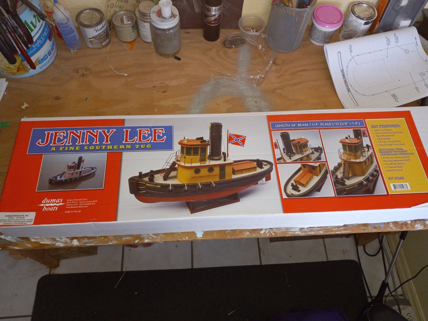
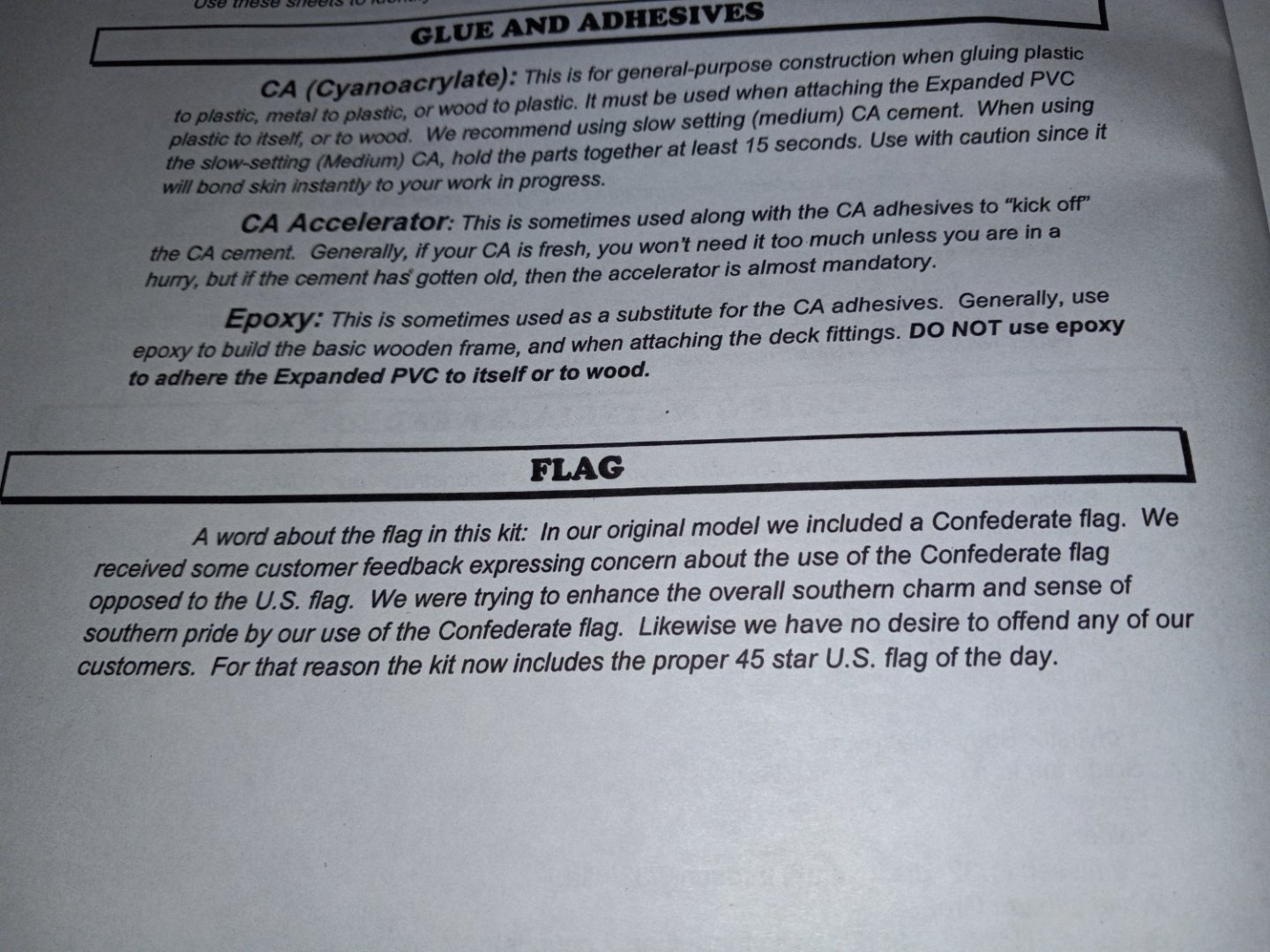
 I picked this orphaned kit up a couple of years ago intending to build it for my youngest grandson. So it has found its way to the building table. It's an r/c model. It will measure about 24 inches when finished. I will not be adding a stars and bars flag and will opt for an American flag.
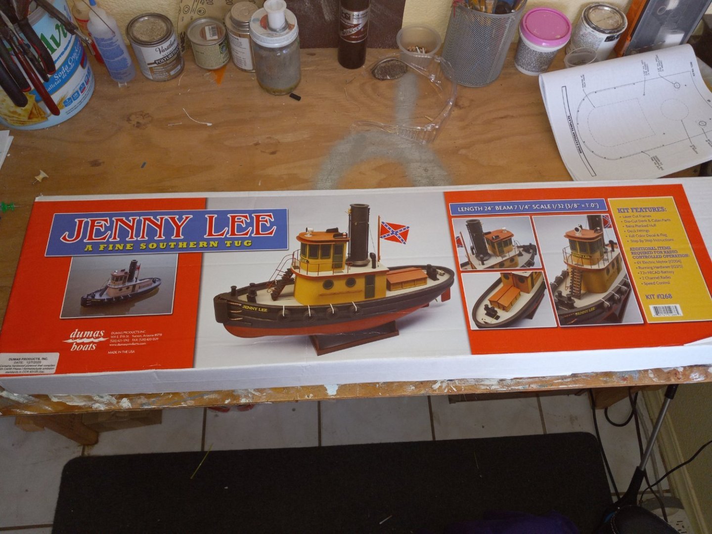
-
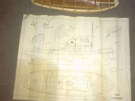
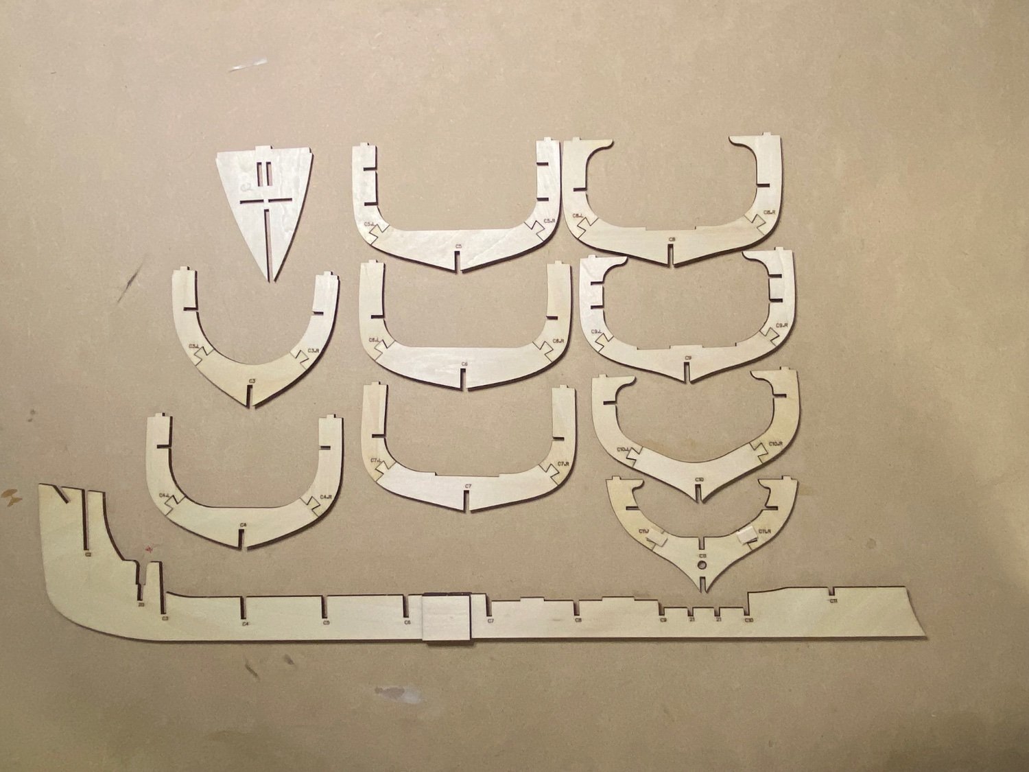
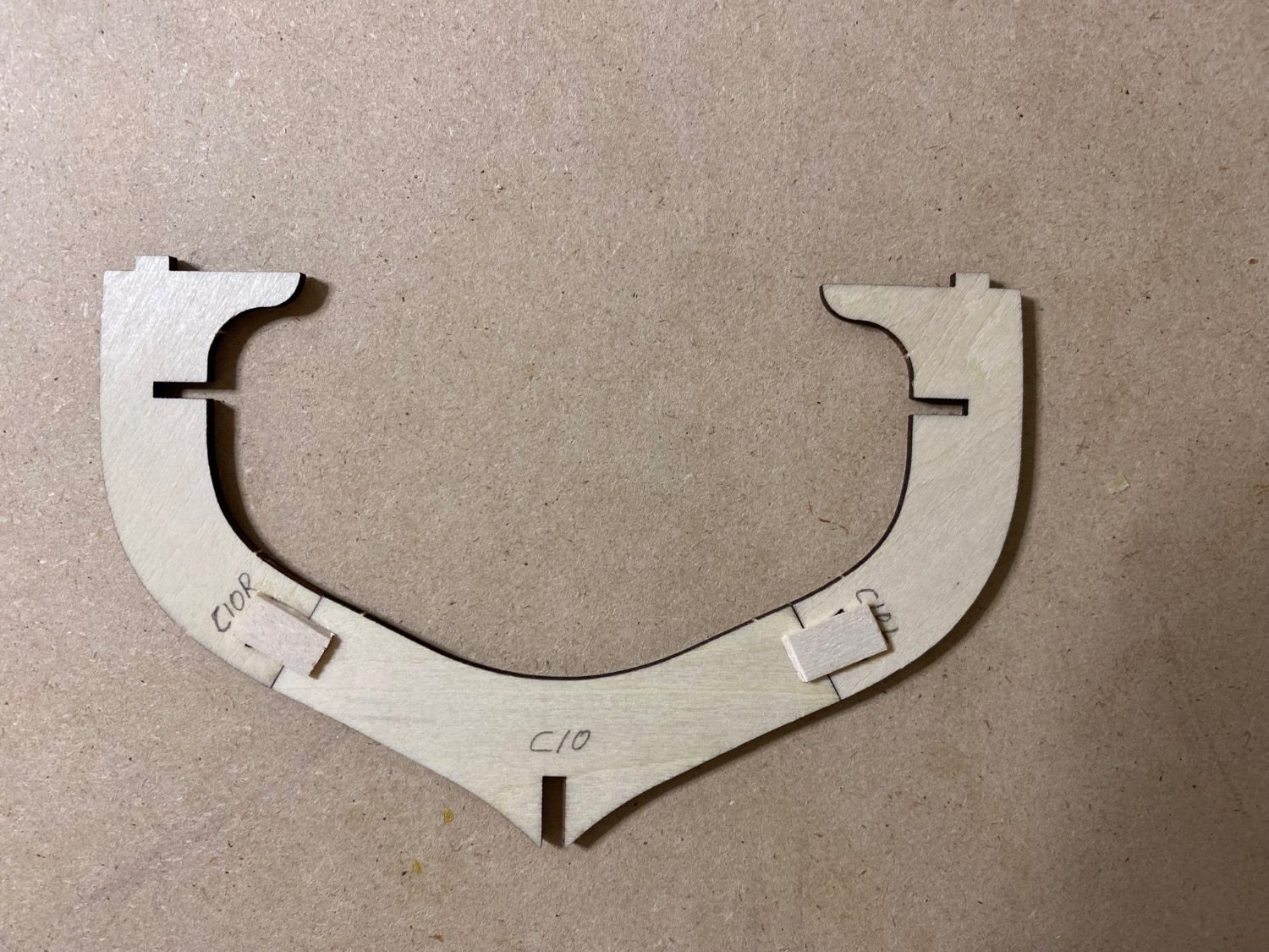
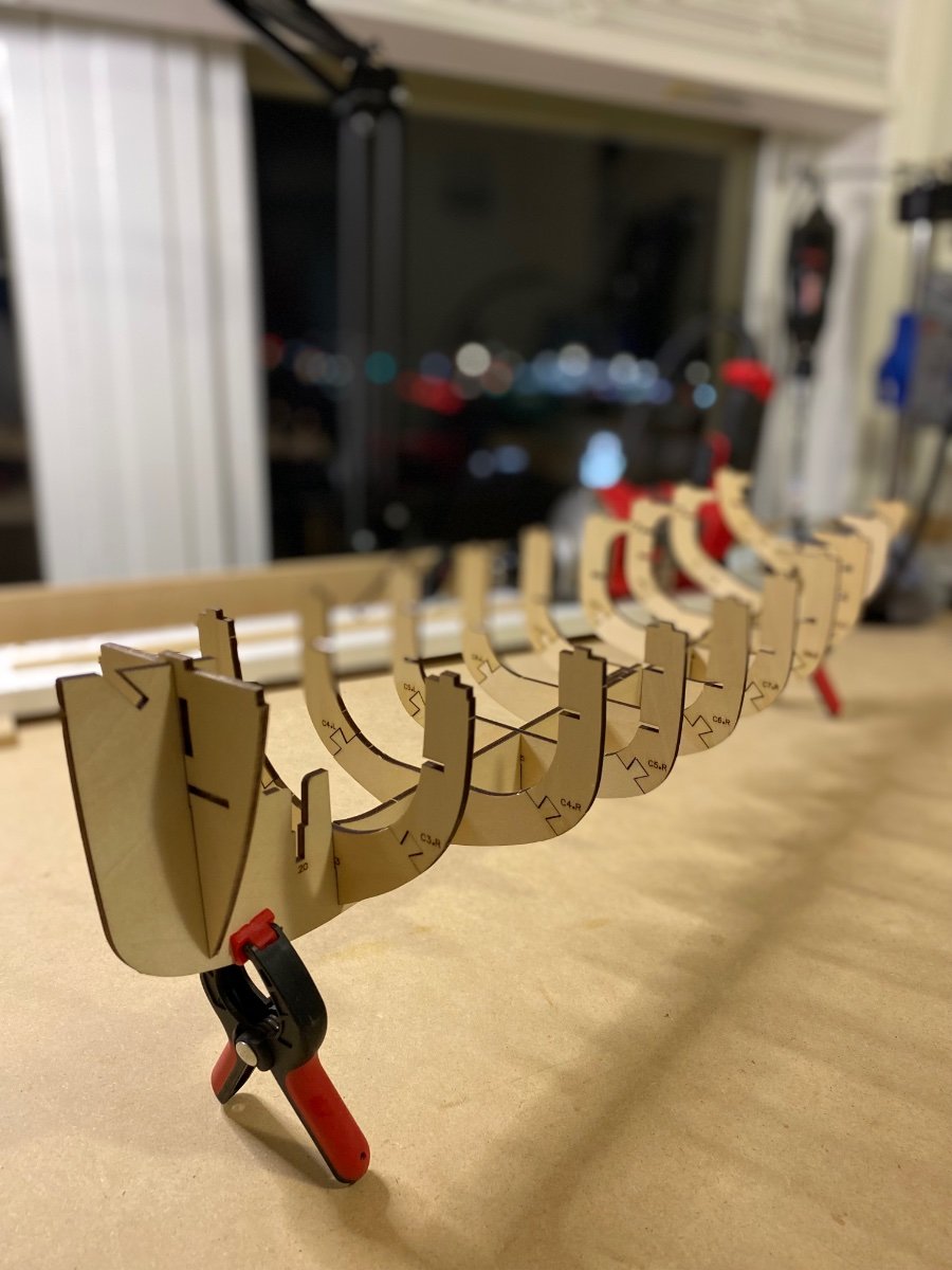
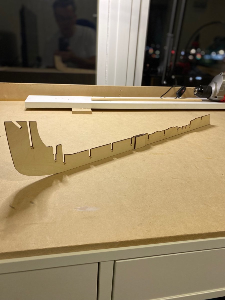
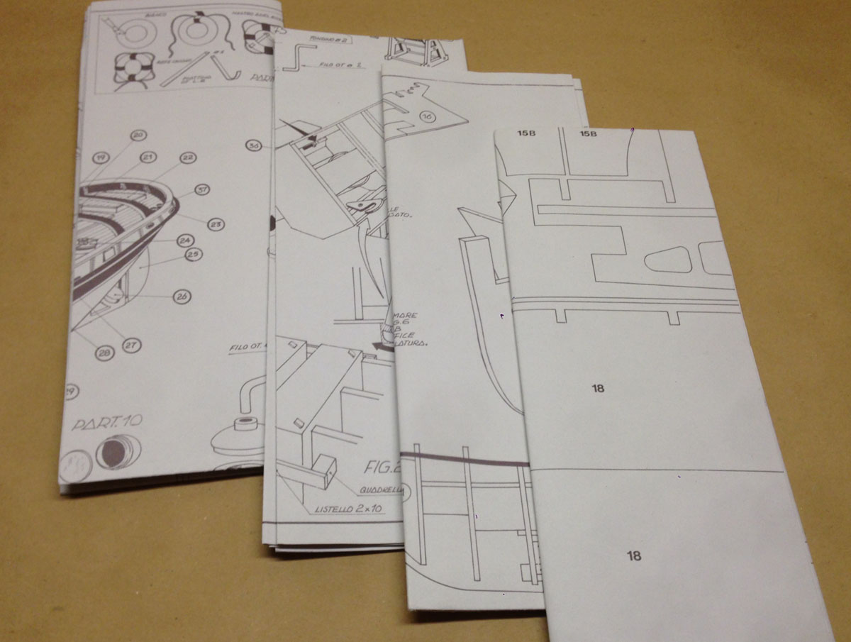
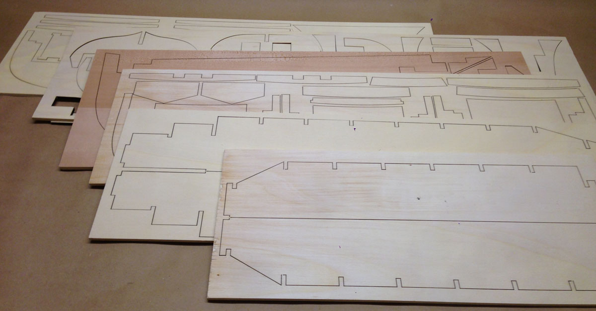
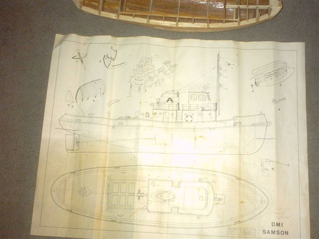
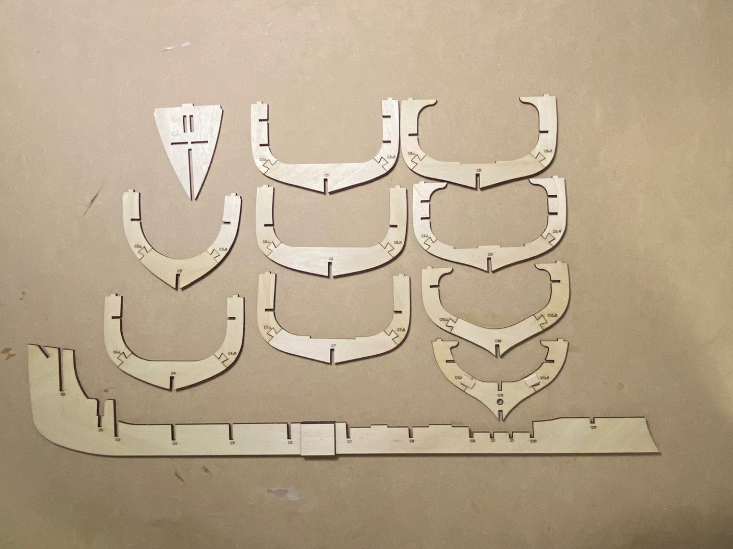
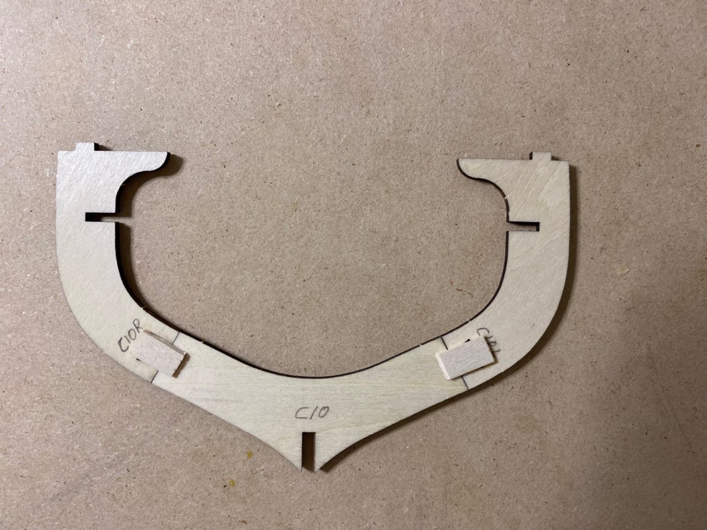
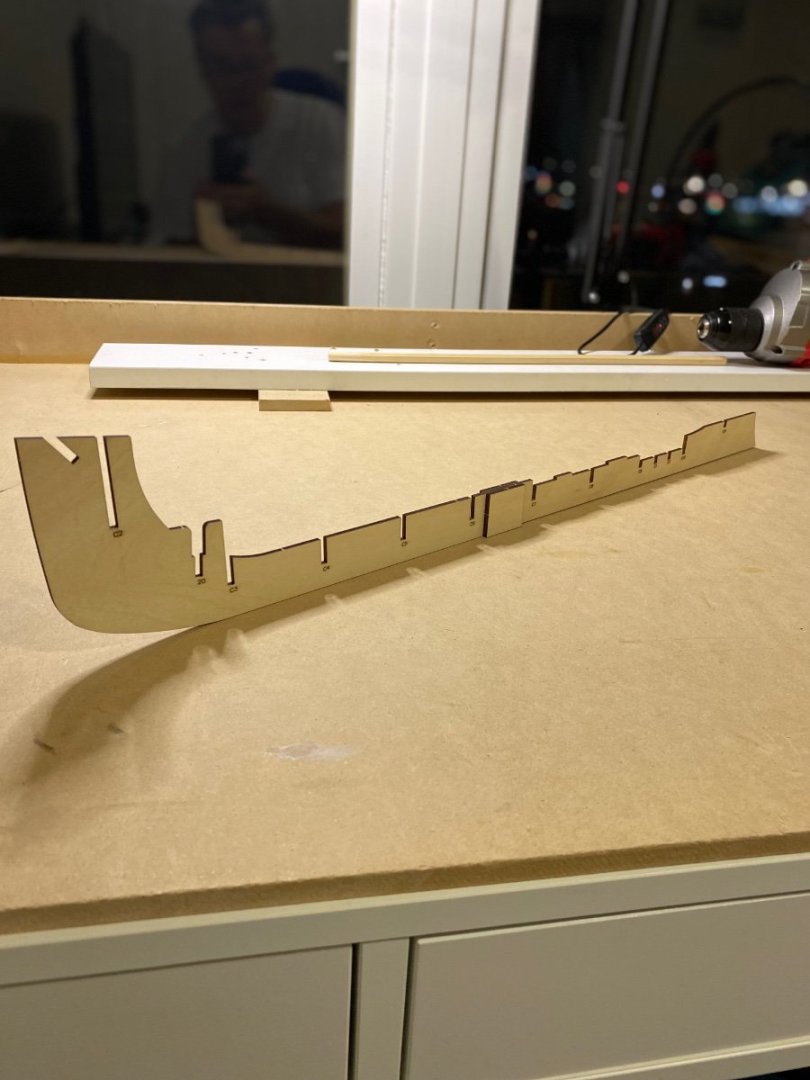
 I have started my second build, the Sanson Tug. There are no instruction included with this kit, it is done through You Tube videos, 18 in total. The 3 piece frames and keel are all glued up. The dove tail joints are all a bit sloppy so reinforcement was added to one side. I will add the frames to the keel next and add the longitudinal braces. #11 frame is very loose so special care will be taken.
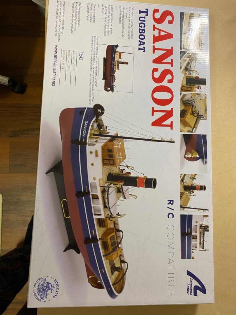

- 42 replies
-
- 8
-

-
- Sanson
- Artesania Latina
- (and 1 more)
-
 Hi all, well this is my first post for my first ever scratchbuild for my first boat. The plan is to build a 1:24 model of the steamtug Wattle. I have just received three sheets of plans and there is a comprehensive article in the winter 2013 Model Boats special edition, so I am ready to go. My background is that I am a lifetime railway modeller (https://www.rmweb.co.uk/forums/topic/157222-charlton-bridge-4mm-brs/#comment-4078299) and i have scratchbuilt much of that. So although this is my first boat build, I am fairly confident about what I am doing. I am based in Somerset, UK. The article suggests 3mm ply for the frames overlaid with 3mm balsa planks that are then sheathed with fibreglass sheet. i have a 3d printer and i think that i should be able to 3d print various fittings etc - eg the rudder looks ideal for 3d printing as do portholes and deck fittings. My first step is to copy the drawings, print out the frame plans, stick them to the ply so that they can be cut out. I need to get over to the local model shop to buy ply and basswood (for the keel). Then I need to source some 3mm balsa so that i can cut planks. So my first basic question is about sticking the printouts to the ply. Its got to be stuck down well enough so that the frames can be shaped, but i guess loose enough so that the paper can be removed afterwards...and soaking in water to release glue doesnt seem a good idea! Whats the best approach for this? All other comments are welcome! Ian
 -
 I have been very remiss in not posting this log. So let me make up for my omission. and please stay with me while I share my complicated story. In late July of 2018 a friend came to me and said "you build model boats don't you?" And when I said yes he handed me a piece of paper with a name and phone number on it. He said "Call this guy. he has money". And with that my adventure began. When I called the guy (his name is Mike) it turned out he is an instructor for a school that trains students for careers in the maritime industry. The school has a harbor tug that is approx. 70 years old and needs to be retired. They don't have a lot of money and came up with the idea of building a model of a tug as an inexpensive way to teach about a modern tug until they can raise the money for the real thing. So they offered me several $1000 to build this model and a fueling barge to go with it. They wanted a tug model that was approx. 4 feet long. As mentioned elsewhere in this site I have been learning Fusion 360 and experimenting with 3D printing. So I thought what a great opportunity to use these skills. Never in my wildest dreams could I have imagined what happened from here. Both good and bad. Thanks to this wonderful web site I already knew about someone who had used Fusion to make 6' long 3D printed Battleships. So my first contact was to get an estimate of what it would take and how long. I also knew that my good friend Dr. Per had much more experience in CAD than I have and reached out to him. So I won't go into all the details. but as it turned out This school is part of the federal government and it took several weeks to just get approval on how not to spend any US tax dollars to do this project. It took many more weeks to get connected to the company that designed the Tug. And finally with the help of an attorney and an NDA. We got to spend a day on board the tug here in Seattle and received partial plans. So the non modeling part of this project took 4 1/2 months. Neal was given 6 weeks to develop the CAD drawings and then we had a design review with the customer. All of this was completed 12/21/2018. And now we could start actually modeling. I should also mention that the project was being funded by donations from a 3rd party and it took a while but we got set up as a vendor to them and got paid an initial $500.00 to cover materials.
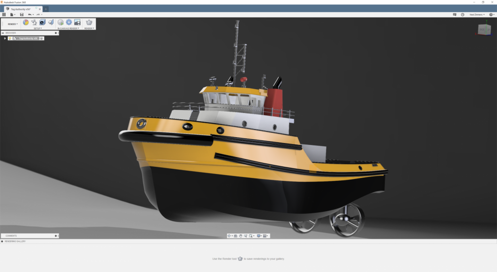
- 133 replies
-
- 13
-
-
- alert class
- tugboat
- (and 1 more)
-
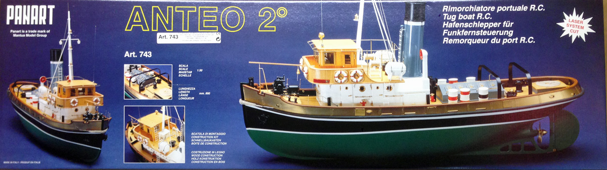
 I've made several ship models in the last 10 years. My best work was on the HM Bark Endeavour by Caldercraft, but the model that gets the most compliments is my Anteo Harbour tug. I've been wanting to build another tug for a while and settled on the Marie Felling by Caldercraft. They offer a couple of other tug kits but they are nearly impossible to find at the moment, so I settled on the Marie Felling. This is a BIG model, 43.5" long. It has a Glass Reinforced Plastic (GRP) hull and superstructure and is clearly made for RC. I just build for the fun of building, and will build this as a static model. Here's a photo of the GRP hull next to my Anteo. MSW has no build logs for Caldercraft tugs or the like, so I hope that this will give the readers some information about this. There are three good build logs on https://www.rcgroups.com, all of RC equipped models of course. Here are links if you're interested. Marie Felling by Longbike Marie Felling by Rmay Marie Felling by Kaskazi
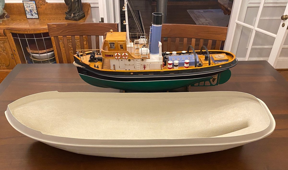
- 50 replies
-
- 8
-
-
- Marie Felling
- tug
- (and 3 more)
-
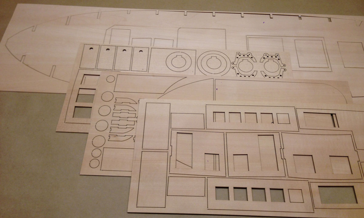
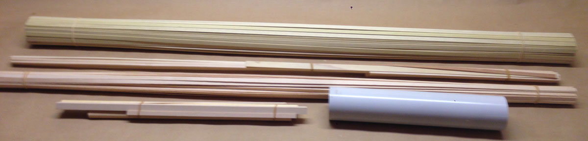
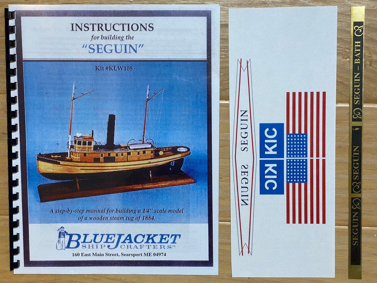
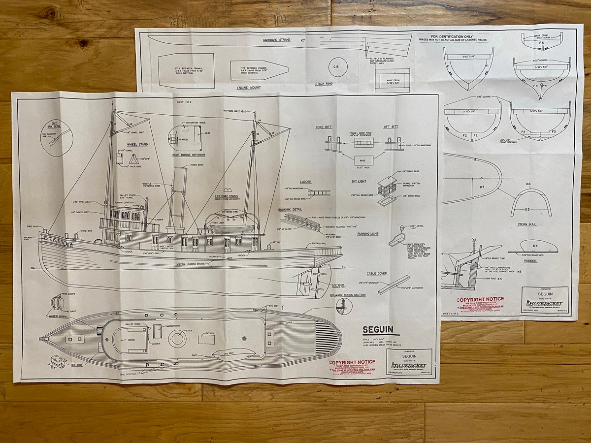
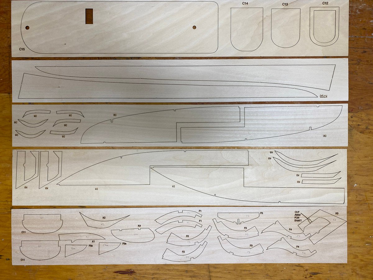
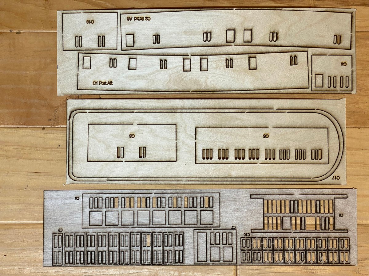
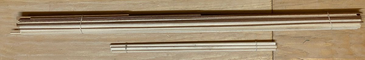
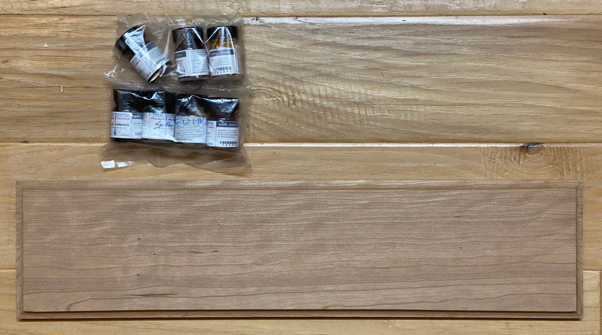
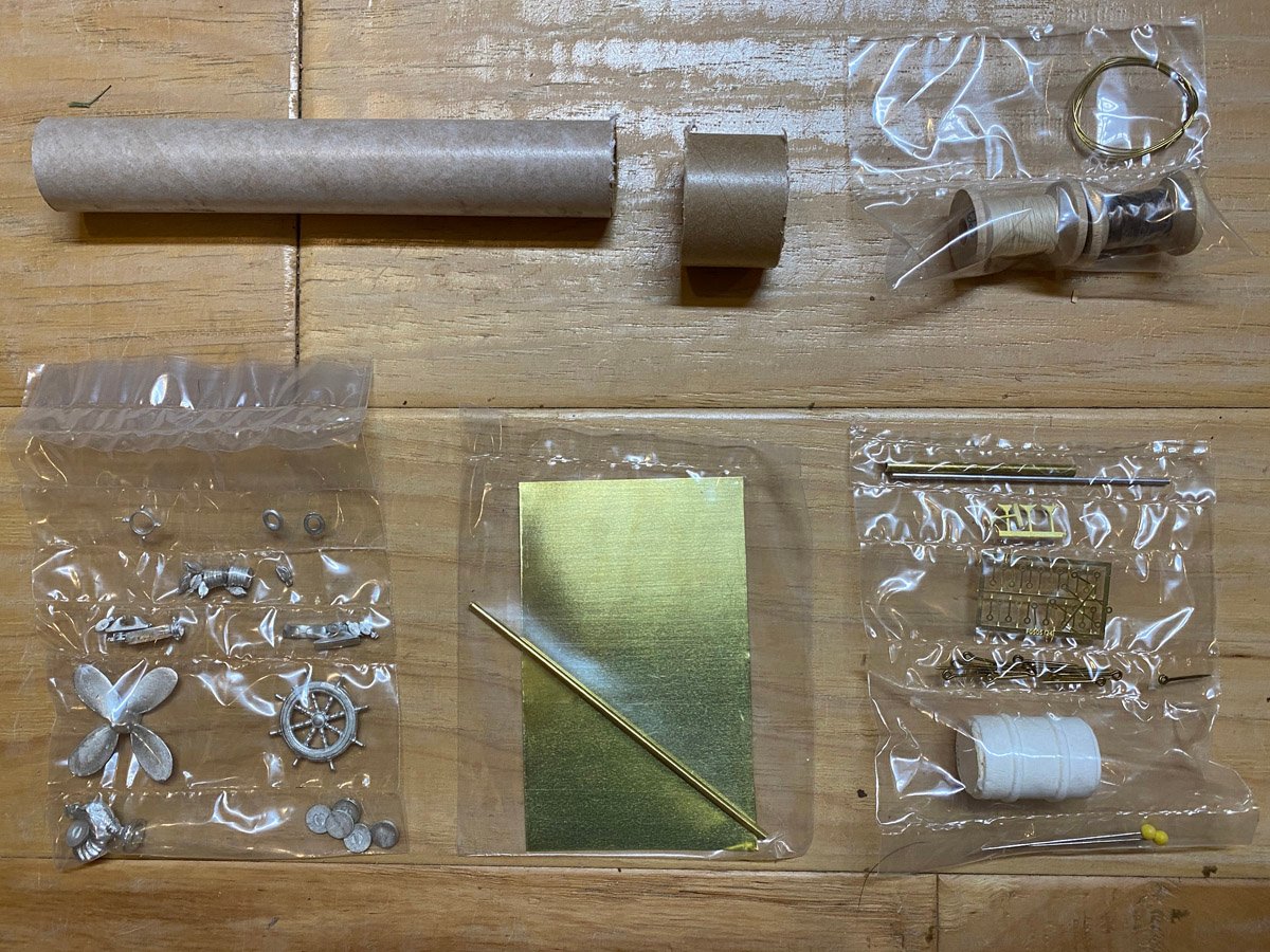
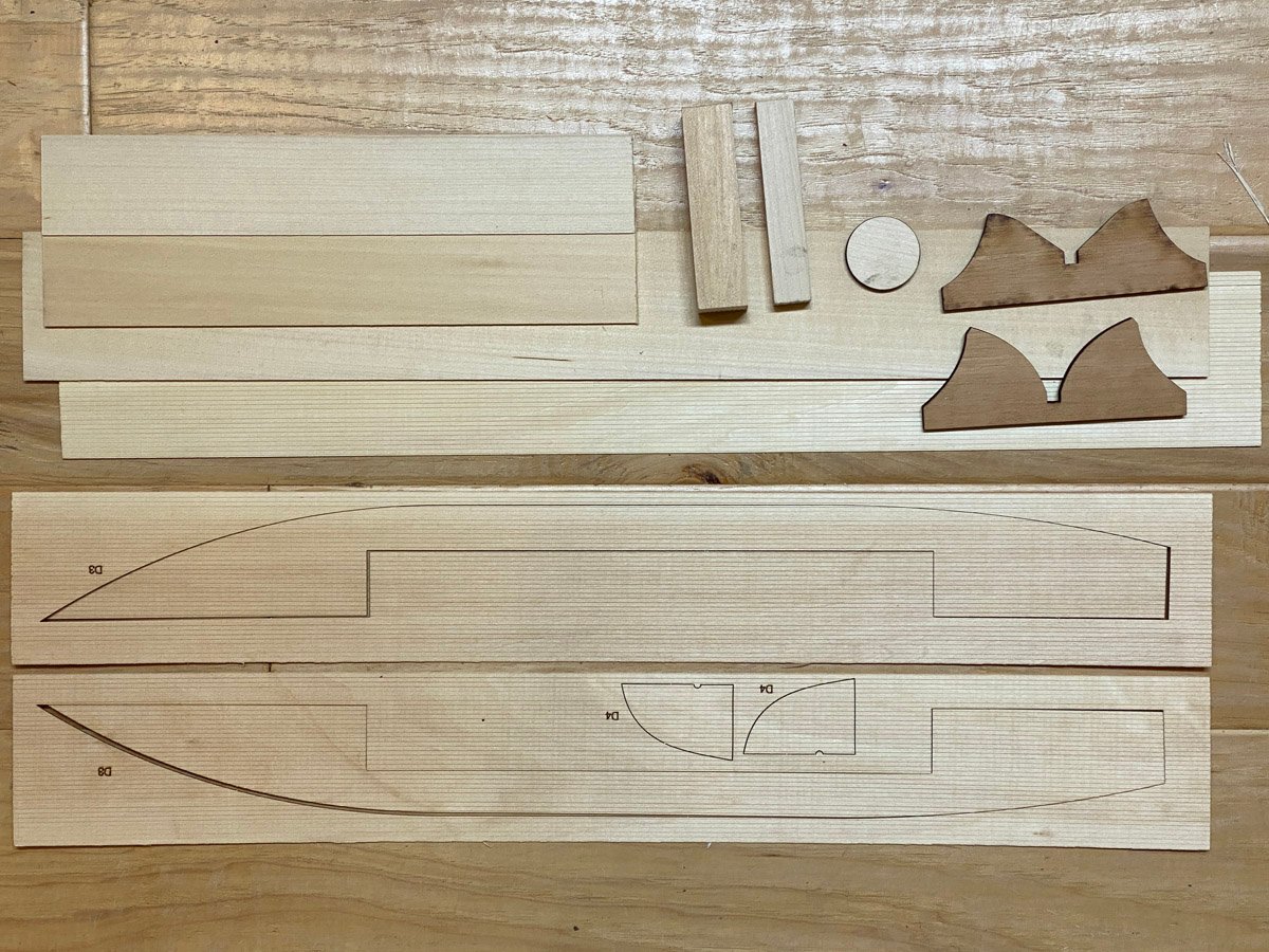
Introduction Back in May I was working to complete my Amati Bismarck model when my wife asked me what I wanted for my birthday. I thought that something smaller, with plenty of wood to cut, and no plastic or photo-etched parts, would be a nice change. I had actually had my eye on Bluejacket's Seguin kit for a while and asked for that. I built Bluejacket's Arleigh Burke destroyer in 2016 so I know that they make quality products, and I have bought lots of miscellaneous parts from them in the past and know that they provide good service. There are only two other build logs of the Seguin on MSW, and neither of them got very far. I hope to show some completed photos eventually. What's in the Box Instruction manual, flags, and nice gold-printed labels. There are lots of photos of cheap, souvenir models of the Seguin on line, but almost no nice photos of a completed model. The photo on the cover of the instruction manual is one of the best. The inside of the manual has been photocopied so many times that many of the photos are hard to make out. This really needs to be reprinted. Two sets of (almost) full-size plans for details and framing. Note that the plans say "For identification only, images may not be actual size of lasered pieces." They are very close, but I always prefer to trust the plans over the laser-cut pieces. Five sheets of laser-cut pieces, perfectly cut with minimal charring. Nicely scored decking and paneling, miscellaneous wood stock, and (cherry?) cradles for a stand. The instructions say to take the large solid block and remove anything that is not a lifeboat. I may look for an alternative. Laser cut pieces for the cabins. Basswood and mahogany sticks, and dowels. Cast prop and wheel, brass pieces, rigging thread, and poorly-cut model rocket body tubes for the stack. Oh no! There are some photo-etched eyelets in that bag! My wife bought the optional paint set and cherry base. I usually rout my own base but this one is very nice.
-
 After a long break I'm back in the boat building business. This time there will be no tiny knot detailed rigging. Fingers don't work anymore.
- 94 replies
-
- 3
-
-
- tugboat
- BlueJacket Shipcrafters
- (and 1 more)
-
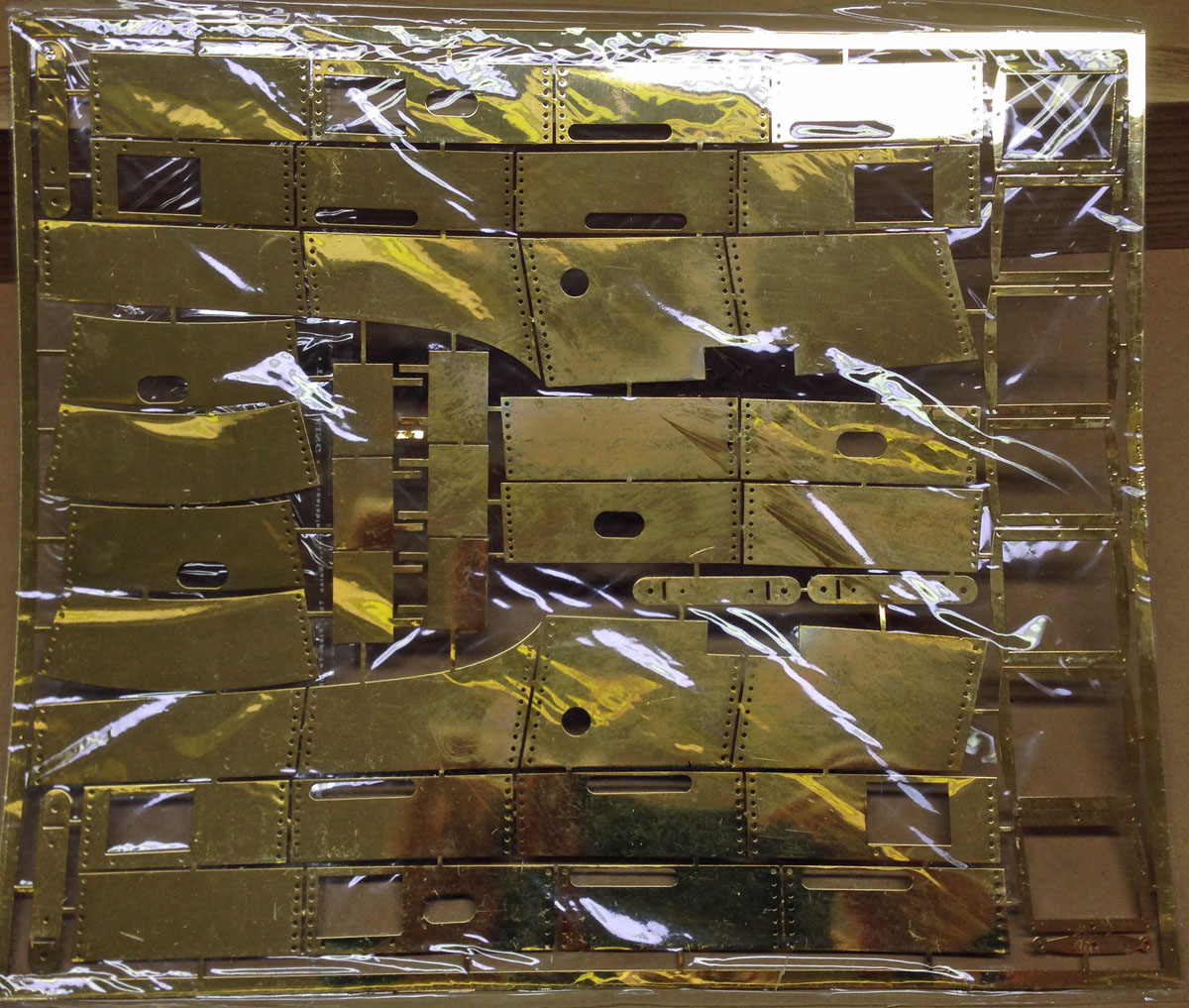
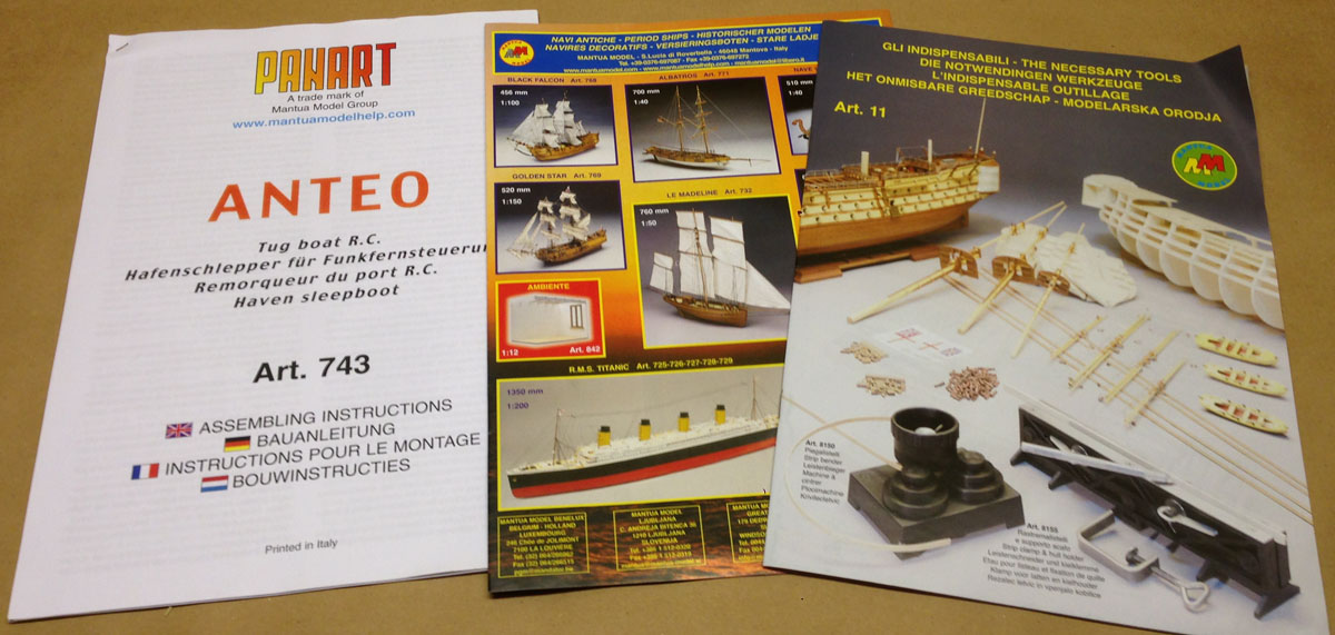
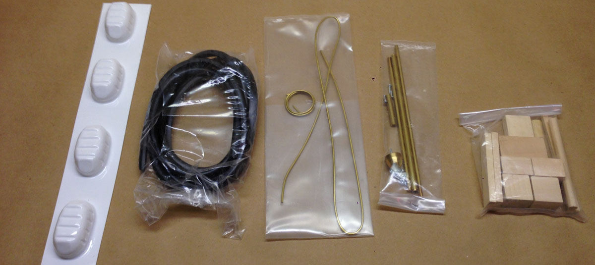
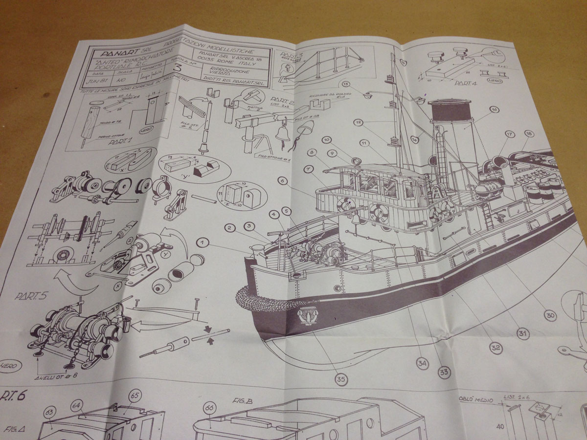
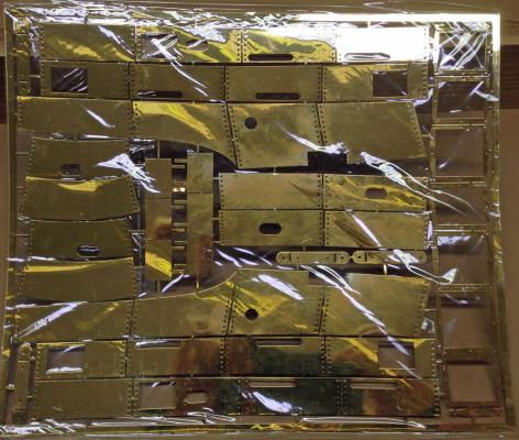
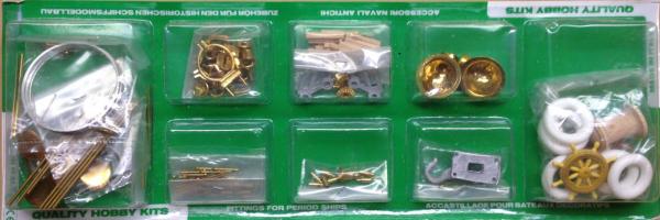
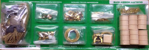
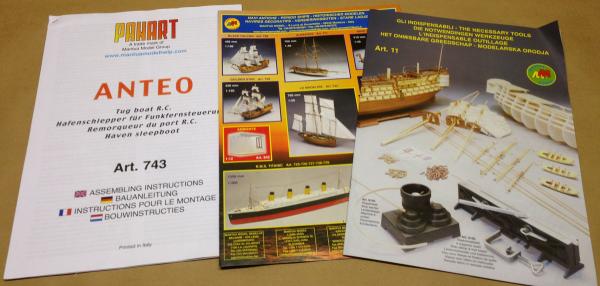
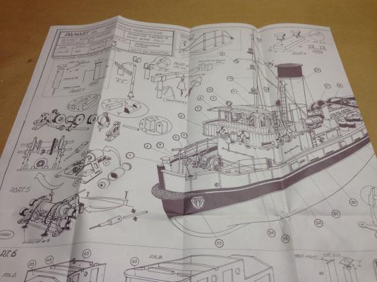
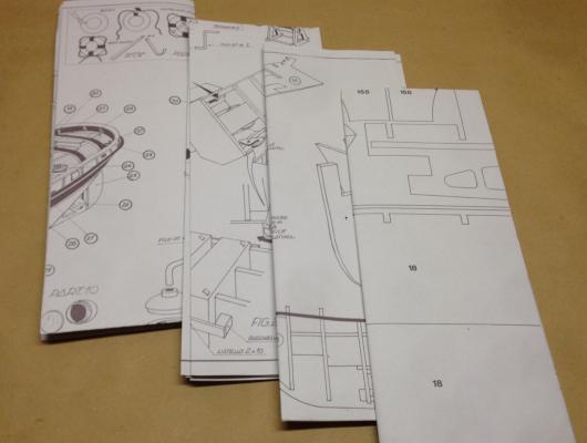
Another Very Different Model (for me, anyway) My wife gave me another ship model this Christmas. Of course I gave her strong hints what I wanted. What I wanted was a working vessel with clean lines, a planked hull, and no rigging. After a long search I found the Anteo harbour tug by Panart, which seems to be a part of Mantua models in Italy. Please let me know if I am wrong about this. I ordered the kit from Cornwall Model Boats in the UK. Even with shipping to the US their price was significantly cheaper than anyone else. I ordered the kit on a Sunday and had it in my hands the following Thursday. Amazing service. I gave the box to my wife and opened it on Christmas morning. What's In The Box. First of all, the box measures 37x11x4 inches and weighs a whopping 12.5 pounds! It is packed with quality parts. There are two packages of fittings including funnels, the wheel, tires, the prop, line, portholes, lights, and the anchor. Planking for a double-planked hull , heavy PVC stack. Vacuformed lifeboat shells, rubber bumper material, brass prop shaft. 6 sheets of 1/4" laser-cut ply. 4 sheets of thin veneer ply. A large sheet of photo-etched brass. Instructions in 4 languages plus 2 catalogues. The English instructions are short and pretty rough. 4 pages of plans, 2-sided, 27x39 inches.


-
 Hello all, I am going to step away from sails for this build and build a boat I’ve wanted to build for a long time. When I started modeling boats I was in an RC boat club in Indianapolis. We sailed One Meters in the summer and in the winter we ran scale RC boats in indoor swimming pools. That’s when I saw a picture of a fire boat called “The City of Oakland”. I wanted to build it 25” long (1:48 scale) with working water pump and monitors. That was about ten years ago. Since then I have been searching the web for all I could find. And what I found changed my mind as to the build. City of Oakland The City of Oakland was originally the yard tug HOGA YT-146. The keel was laid down 7/25/1940, Launch date was 12/1/1940 and it was delivered to Pearl Harbor 5/1/1941. (This is from the web) City of Oakland, ex-Hoga, is of exceptional significance in American history as the only known surviving yard craft present at Pearl Harbor during the Japanese attack on the U.S. Pacific Fleet on December 7, 1941. Hoga fought fires on Battleship Row for 72 hours. The actions of the tug's skipper and crew did not go unrecognized. On February 1942, ADM. Chester A. Nimitz, CINCPAC, commended McManus, his men, and their tug for a job well done: “For distinguished service in line of your profession as Commanding Officer of the Navy Yard Tug HOGA, and efficient action and disregard of your own personal safety during the attack.... When another ship was disabled and appeared to be out of control, with serious fires on the fore part of that ship, you moored your tug to her bow and assisted materially in extinguishing the fires. When it was determined that the damaged ship should be beached, as there was serious danger of her sinking in the channel, you assisted in the beaching operations in an outstanding manner. Furthermore, each member of the crew of the HOGA functioned in a most efficient manner and exhibited commendable disregard of personal danger throughout the operations.” Placed on loan to the Port of Oakland, California, in 1948, it was returned to the navy after 40 years of service. Recently it was awarded to the City of North Littlerock, AR. to be in their museum. At present it is in a boat yard near San Francisco being prepared for transport to North Littlerock Hoga is one of about 30 of the Woban YT-138 class. The problem in this build is that there are no line drawings of this boat. I have many, many pictures and internal equipment drawings but no lines. I hope to build the Hoga as it was at Pearl Harbor prior to the attack. I got the build plans for the Billing’s kit and I will scale the bulkheads and keel to 1:96 and see where to go from there. So wish me luck and follow along with me. Bob Hoga at sea trials Hoga at Paerl Harbor


-
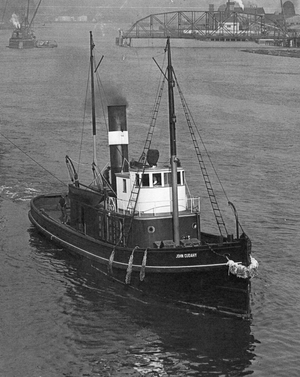
 I know this is not a stick and string type build, but I enjoy building vessels of local interest. The John Cudahy was built in Ballard Washington in 1900 for the fisheries trade. In 1904 she was sold to a tug firm in Grays Harbor and was rebuild for tug work. Her duties included ship assist and log raft towing. She was sold several times during her stay on Grays Harbor and went thur several changes. She went to work on the Columbia River for a number of years before being sold again. Foss tug bought her and rebuild her completely. Added length, changed to diesel power and renamed her Henry Foss. She was lost in Alaska in 1952. The period I chose to model is sometime after her conversion in 1905 to about 1915.
- 208 replies
-
- 8
-
-
- john cudahy
- finished
- (and 1 more)
-
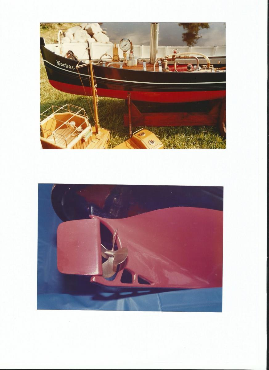
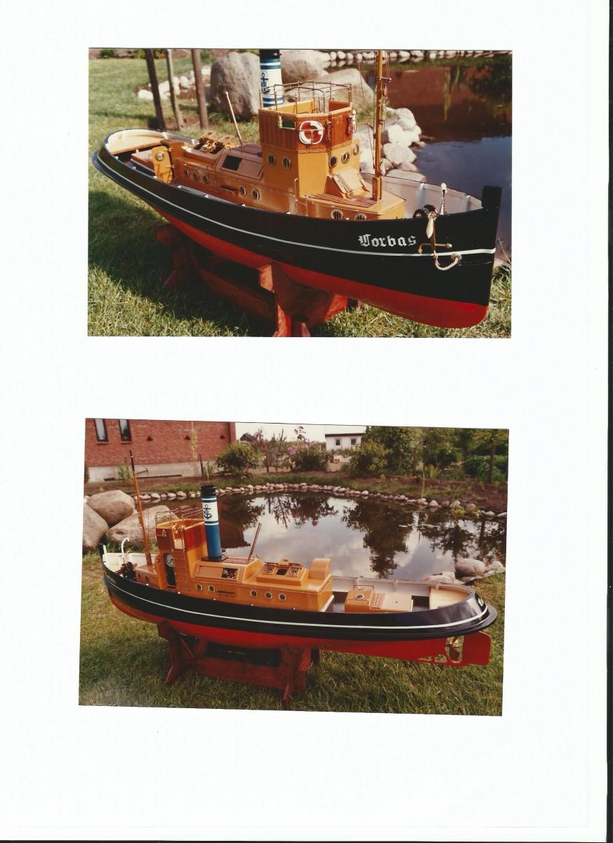
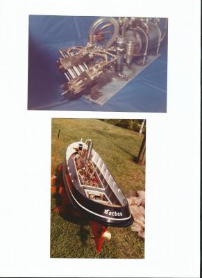
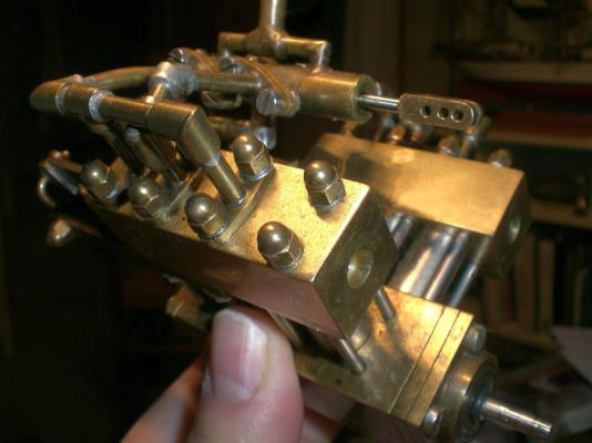
 Introduction : This project has been completed already in the years 1984 / 1985, when I was still a young man. I had the intension of building my own designed steam engine for a model ship. A regular steam engine with crosshead-guides and Stephenson reversing control device, was too complicated to build, in lack of neighther lathe nor milling machine (still do`nt have….). So I decided to design a steam-motor with a minimum on moving parts, and yet powerful enough to propell an appr. 1100 mm long RC controlled ship model. And the driving challenge was also to see if I could do it anyway…… Current status : After some years of perfect performance, the boiler became a hair crack leakage in one or two of the inner heating tubes solderings, that unfortunately could not be mended without destroying the boiler. So neighther ship nor motor had been moved since. I wanted to rotate the motor the other day by trying to rotate the crankshaft but all was blocked somewhere, probably the pistons are sticking to the cylinder walls. Shall have to dismantle everything completely for overhaul, and build a new boiler if I want to have fun on that behalf again. Fortunately the was a raghther short little super 8 Kodak film made of the model travelling on the lake at full steam in those wayback years, the film in miserable quality, but at least a document of a successfully completed project. I`ll try to put that film in a little video here on MSW in this log later on. Some of the pictures I found fortunately in my photo-archive and scaned them in, and was myself surprised that I even had pics of motor complete, and boiler in the building stage. I thought this may be of interest for the one or other fellow builder here at MSW. The ship itself is still ready to be launched at any time, only the prop has a bit patina on it The ship Model-length 1090 mm Steam powered, gas fired, RC controlled, fictional version river tug “Lorbas” in nostalgic look Model Build year : 1984 / 1985 Ship is POB scratch design, self drawn lines, ply frames and diagonal planked with balsa stripes, Hull coated with glass-fibre rowing cloth and epoxy resin Removable deck housings and many maintenance opening hatches and doors, and ventillation openings for the boiler- and machine room large self made 80 mm 4-blade brass propeller RC control Simple oldtimer 2-channel radio-controller, Make “Robbe” and on the ship two-channel receiver and two servos (one for steam reverse valve, stop, foreward, aft) one for rudder port / stb. One power pack comprising 4 x 1,5 V mignon Batteries. I`m not allowed to use this RC equipment any more due to national postal radio frequency regulations The Engine Self designed Six cylinder Steam motor in Vee-6 design, for superheated steamflow, with direct piston rods to crankshaft, ball bearing crankrod head-bearings, each cylinderhead with common, horizontal working slide cam control bars, manifolds for steam inlet and steam outlet (reversible) Steam reverse valve (for swapping inlet / outlet channels with RC servo function. Motor designed for 2 bar constant steam backpressure when running at 200 RPM in direct (quick disconnectable) coupling to propshaft Idle unbreaked motor runs up to 3000 RPM, if control cam positions are set correct Model speed like modest walking pedestrian Lubrication by means of oiler-device in live steam line (high viscosity steam engine oil) Piston rings made of Teflon in circumferential pistenring grooves Manifold gaskets made from Viton O-rings (heat resistant) Elbow- and t-fittings and flanges silver soldered, tubes soft soldered in Materials: brass and stainless steel and commercial available bearings Six Cylinders 10 mm diam. X 10 mm strokelength Due to the six cylinder arrangement the motor is capable of starting rotation at any crank position The boiler It was my aim to create a powerful lightweight design for firing with butan gas burner and gas from commercial, exchangeable cylindrical cartridges that fit into the boat (like used for refueling cigarette lighters). Function: The boiler has one central flame-tube cross-spicked through with 6 smaller instant steam tubes that mount into the area of the upper steam collector dome. The hot gas of the flametube then reverses direction in the outer end-camber, that also contains the superheater tube coil and from there 13 heating air tubes lead back through the boiler, into the opposite chamber that takes up the chimney tube (inner liner of the ships funnel) The waste steam tube is connected to the inner chimney liner in order to burn out the micro-oil-fume of the exhaust steam in the upstreaming hot air together with the firing exhaust. (avoid lakewater pollution !) The safe running time with one distilled boiler-water filling is 20 minutes The boiler is capable of providing constantly 2 bar backpressure at ships full speed The boiler is equipped with a stand, wooden plank cladding, a blow off safety valve, a pressure gauge, a main steam valve, an oiling device, a water level indicator, a draining point, and a heat exchanger for pre-heating the expanding butan gas from the gas cartridge The boiler is mounted to a common aluminium baseplate that also takes up the motor mounting bracket and the burner mounting bracket. To fire up the boiler, the flame tube is heated with a external (more powerful) gas tourch outside the ship. When reaching 2 bar steam pressure the complete baseplate is set into the ship from above Materials: Boiler complete from stainless steel, silver soldered, pressure tested with 4 bar Enjoy...... Nils
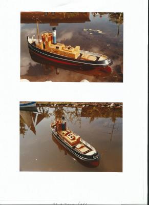


- 32 replies
-
- 16
-
-
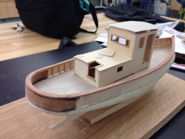
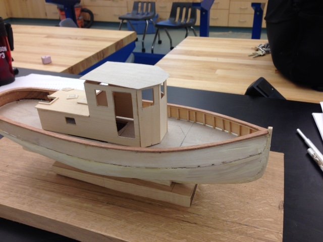
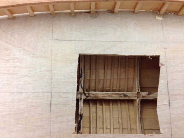
 Akbar was designed by Sam Crocker as the harbor work boat for the boatyard in Manchester MA. Designed in 1951, the boat was used until the early 2000's when it was replaced by her sister ship Masconomo II. I chose to build this boat as it was great to see such a small tug moving about the harbor. I also really liked the look of the mast and gaff tackle. I have built a number of plank on bulkhead models and wanted the challenge of building the curved stern transom. ( I had looked at doing a draketail, but figured I would try this first) I am sorry I joined this group after I began the build, and hope that I can catch you all up on what has gone on so far. The keel is birch plywood as were the bulkheads. I steam bent a number of rib frames into the hull because I want them to be visible through the companionway and windows. I am in the process of carving a model of a Gray Marine 6-330 to fit into the engine room so that it too may be seen through the windows and the companionway. Today I turned the winch barrel and the display mounts from aluminum. ( It's what I had around ) My next step will be to make the interior dashboard and seat for the wheelhouse as well as complete the mahogany trim for the windows.
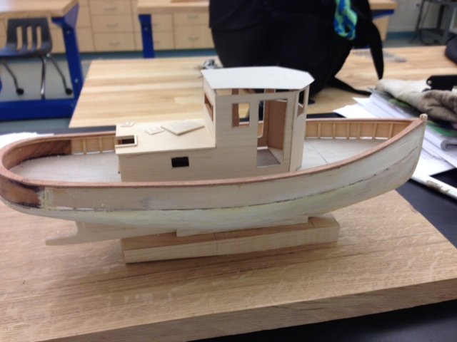
-
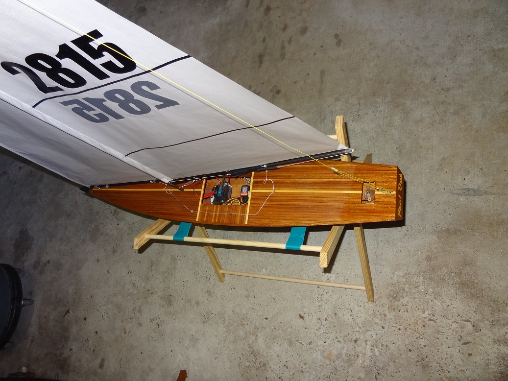
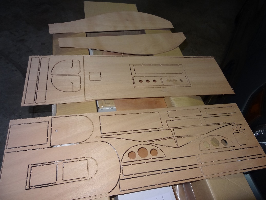
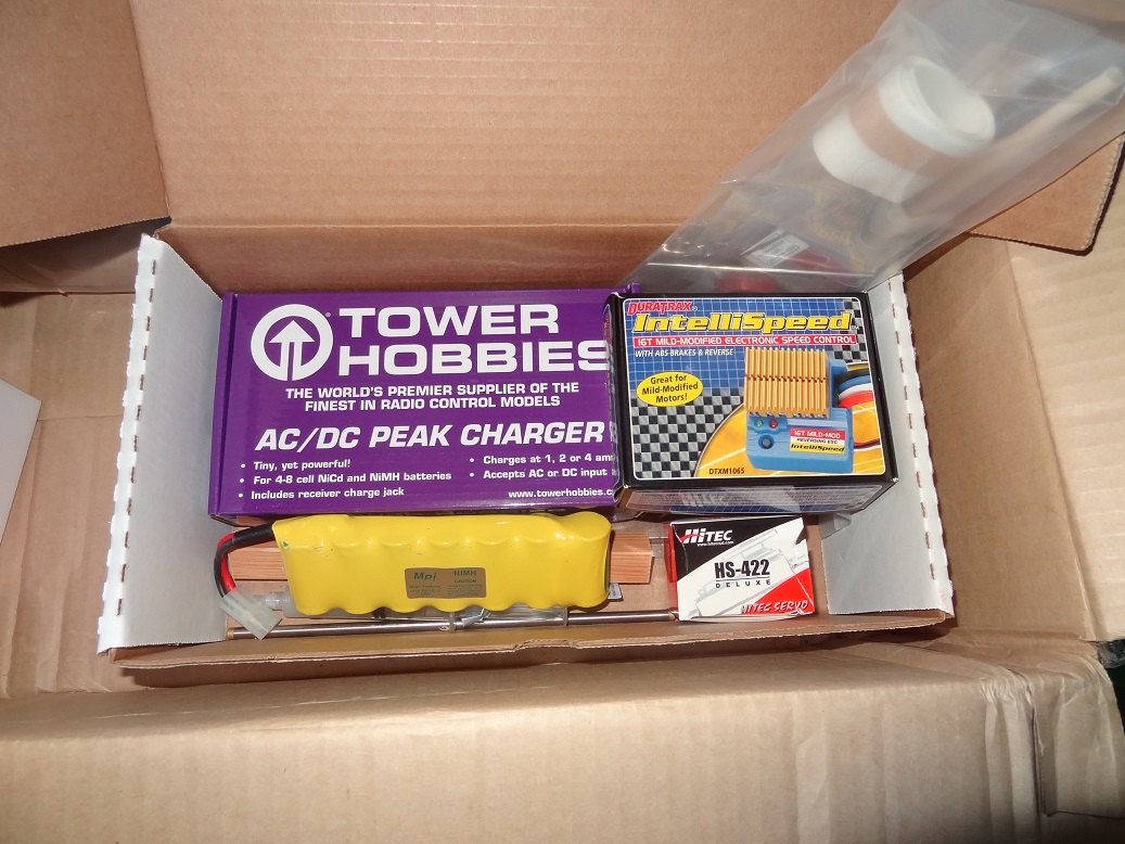
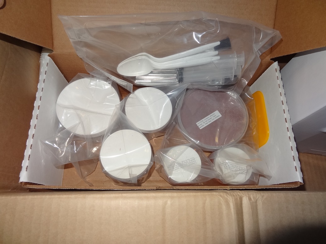
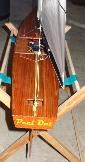
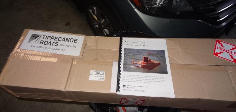
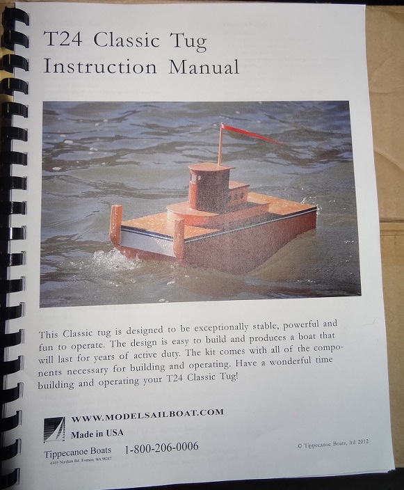
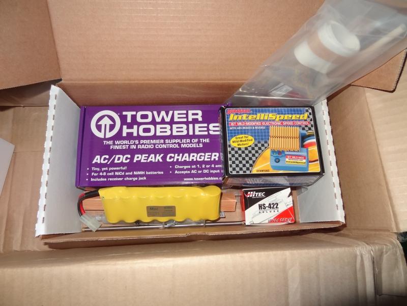
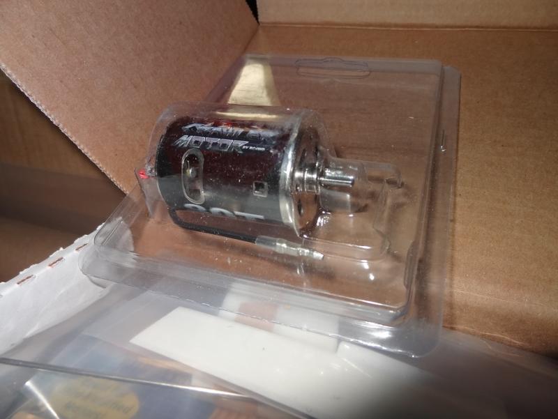
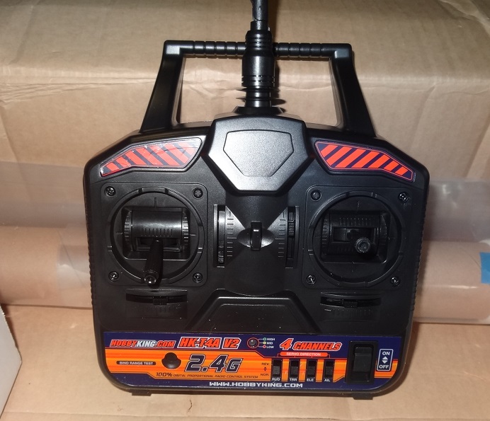
 I posted a question on the Questions forum and everyone seemed OK with me doing a log for an RC tugboat. So here goes. The kit is made by Tippiecanoe Boats out of Washington state. The owner, Will Lesh, designed all the models for sale there. They focus primarily on RC sailboats. Will is a good guy and almost always available by phone for questions. You can't beat that. I have already built one of their RC sailboat kits. I had the itch for one and it seems like you can either buy one RTR (ready to run) or build one. Given what we do here, building one seemed the natural choice. I did not do a log for the sailboat but here are a few quick pix. Yes it's really that big - 37" in length and a little over 5' tall. Does the decking look vaguely familiar? Both the sailboat and tug kits are made from top quality materials. Deck & hull parts are marine grade ply with a mahogany veneer. Marine epoxy is used to fasten all parts. Instructions are extremely detailed. It comes with everything needed to complete the model except paint & varnish. That includes the electronics, epoxy and additives. The tug is not a rendition of an actual boat, rather just a generic model. The looks are pretty basic. So why in the world would I want to build this kit after building highly detailed models? Mostly because I need it. I live on a big lake. Several places where I sail the RC are open water. If something were to go wrong with the sailboat, it would be a long swim to get it back. The water is pretty cold right now - even in Texas. The tug has a rescue arm - a big hook that can snag a disabled boat and haul it back to shore. Also, people race the sailboats. That's usually several floating markers out on the water that the boats sail around. The tug can be used to drop the markers. Lastly, I'm sure it will be fun just motoring around Normally I wouldn't post pix of the kit - we've all seen them right? I'm guessing not too many have seen this one so here are a few. Very detailed instructions including 3 pages on how to use the epoxy. More on that in a sec. Some of the plywood parts The electronics. This kit even included a battery pack & charger in addition to the servos. The epoxy kit. This stuff is way different than the 15 minute stuff we use. Mixing the resin & hardener produces something about the viscosity of molasses - it's self leveling. In fact it is used to "clear coat" the wood in some areas. If you want it thicker (and you will for some applications) you add a thickening powder to the mixture. Needless to say I learned a heck of a lot about the correct way to use epoxy while building the sailboat. The motor RC controller. So there it is. I plan to begin the hull this evening. If I'm lucky this will take about 6 weeks to build. The epoxy slows down the process somewhat. It's not CA - it takes overnight to dry so there is some wait time involved. Thanks for reading!
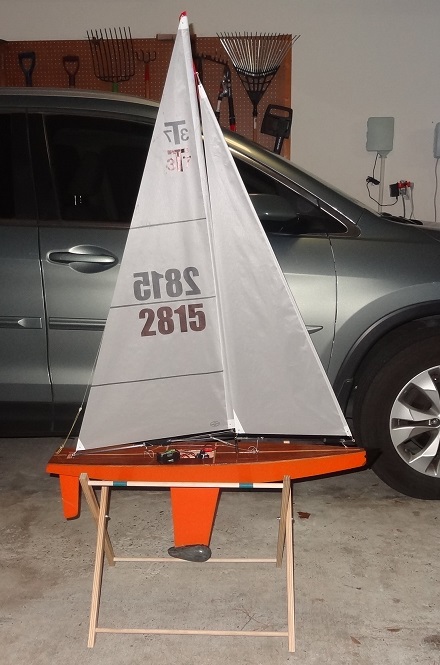


- 96 replies
-
- 9
-
-
- tugboat
- Tippecanoe Boats
- (and 2 more)
-
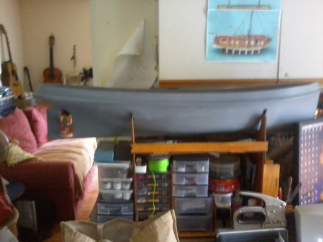
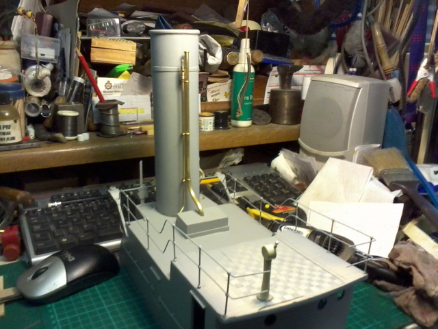
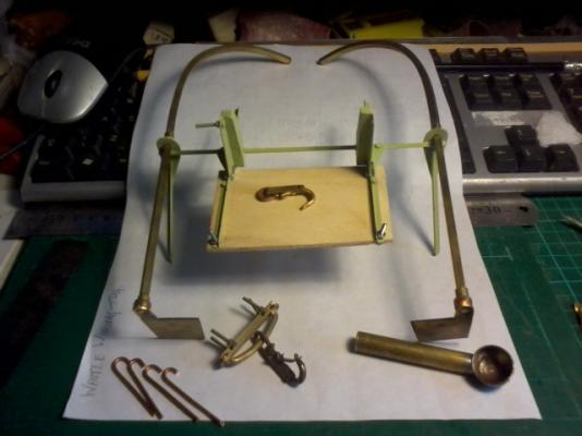
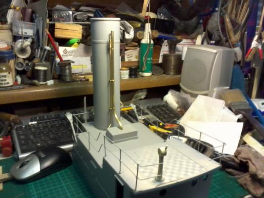
 The Wattle was built in Australia 1933 I didnt start taking pictures of the initial start of building as it had not crossed my mind at the time to do a build log its the first time and I am a bit shaky as to how to go on, so here are some of the first pictures, after final layer of glass tissue and propeller tube and shaft fitted sorry about the poor picture, this was quite a big jump to fitting the rudder and the sponson another leap in time whilst the resin was curing I built other parts wheelhouse, winch, lifeboat part of davits and l/boat cradle latest updates are brass-work on funnel more to come as I progress mick


-
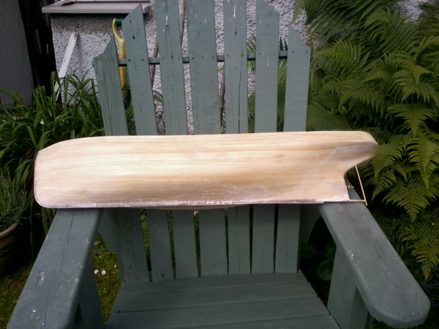
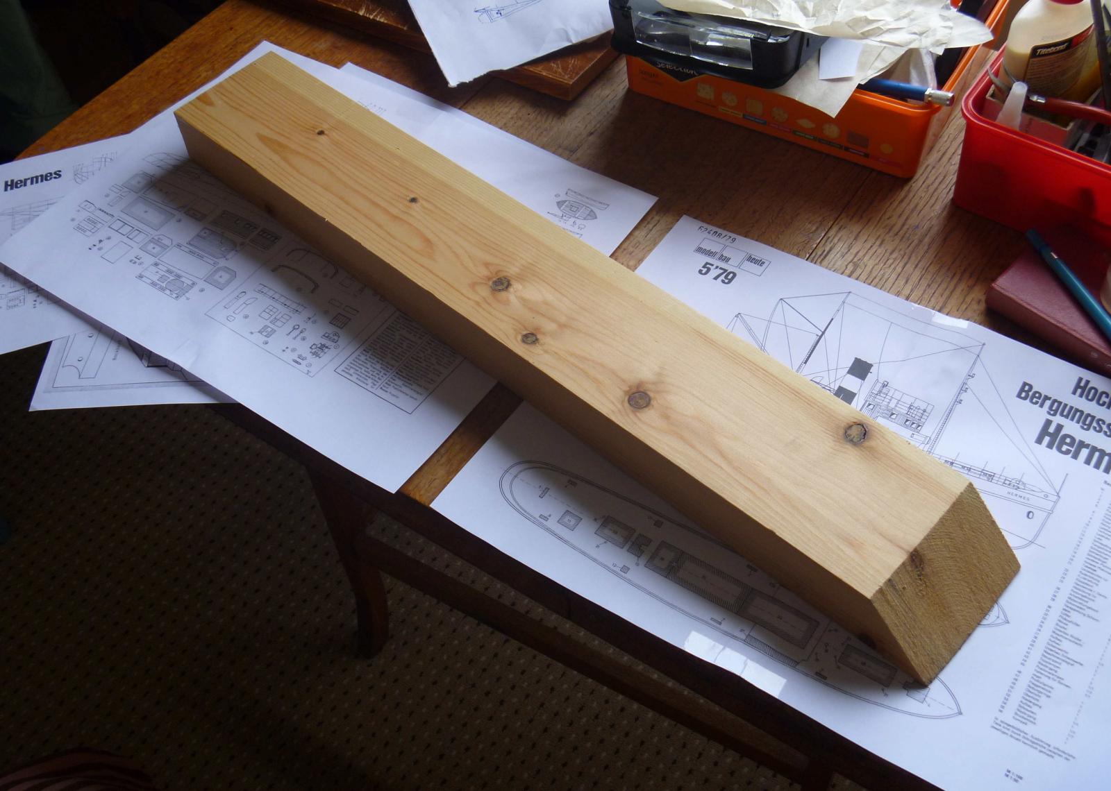
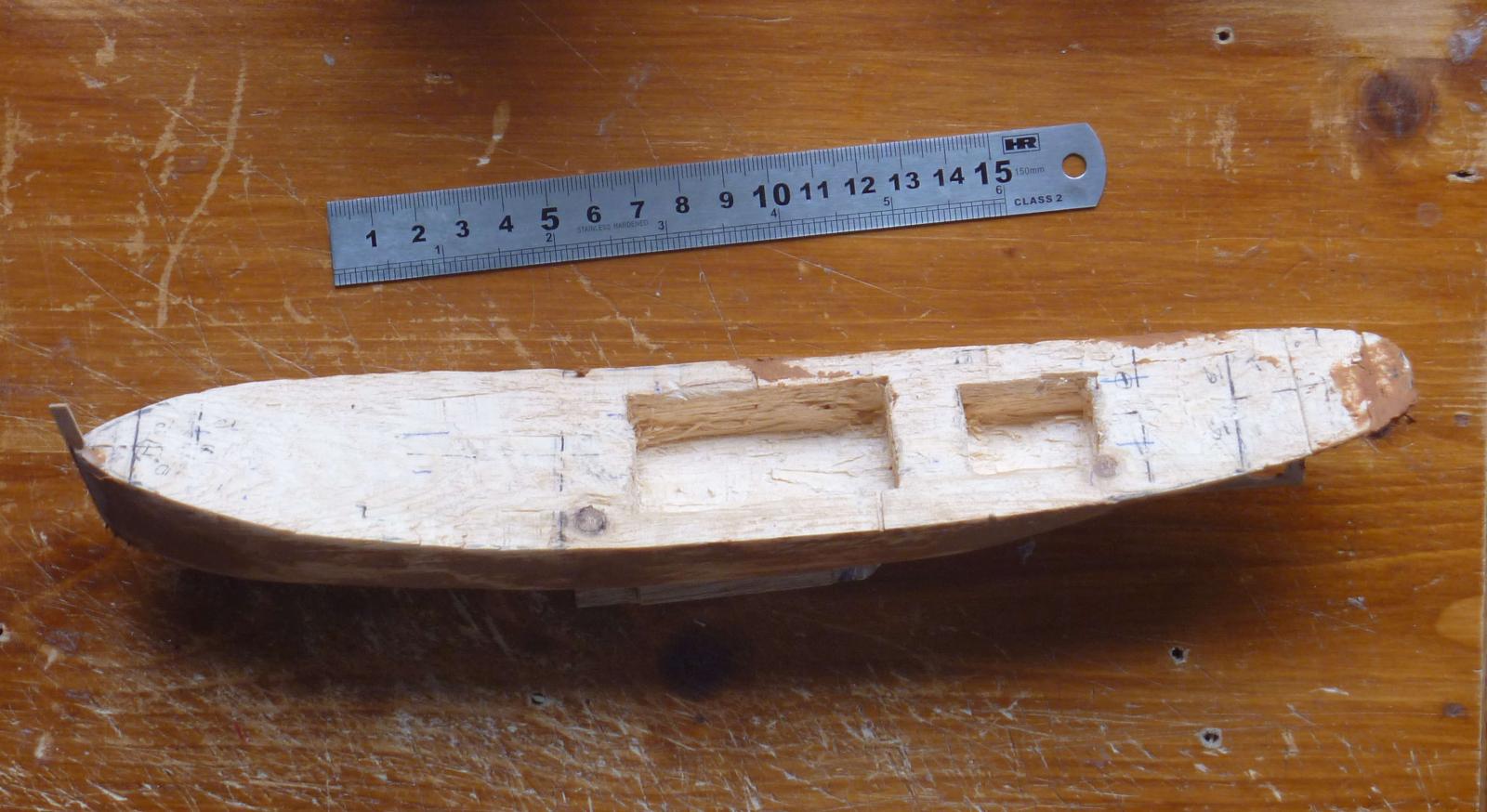
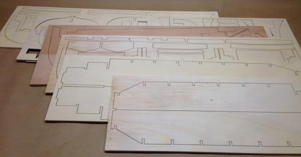
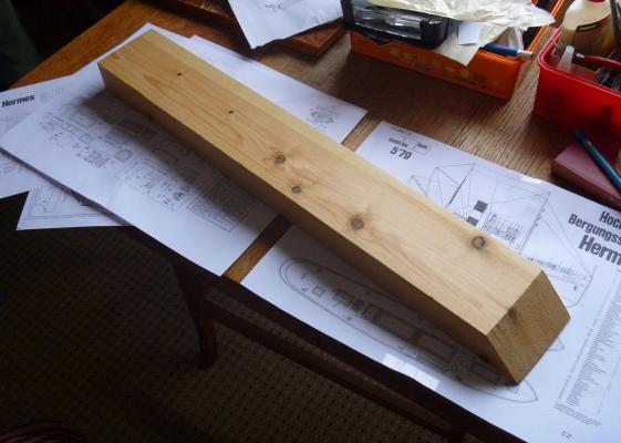
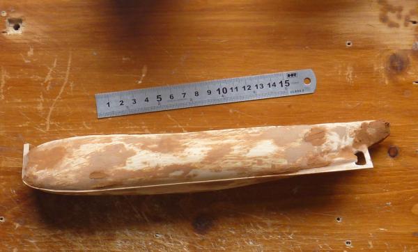
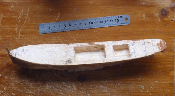
 I wanted to try a tug, but smaller than the 800mm or so of the kits I could find - I like the look of the Occre Ulises, but not the size! I found some plans for the Hermes, a German tug of 1923. I've reduced them to 1/150 approx, which gives a length of 285mm. There will be some modifications: She'll be single-screw not twin, for a couple of reasons: I just think it looks better, and for the machinery space. Which leads to the second mod: she has two cutouts on deck as you can see, and she'll have lift-off deckhouses to show interior detail. The aft space is for a single reciprocating engine (hence single-screw) and the fore space for boilers; I think the original was diesel, but steam will give more scope for details. Also, the compass platform is to be removable, to show the bridge interior. Also, I may build more in timber rather than steel plate, which I think may be more in keeping, but this is open to revision. The attached pictures show the plans; the raw material (a piece of left-over building timber); and the hull as at present, part-way through filling/sanding. The deck openings will be lined, probably in card, so the unfinished interior sides aren't very important although I will tidy them up; the openings are about 5mm larger than the opening in the deck planking will be, to give the impression of depth. Note the German dictionary in the first two pics: I need help identifying the Pilzkopflufter (9 of them) and the single Verspannung Schornstein.
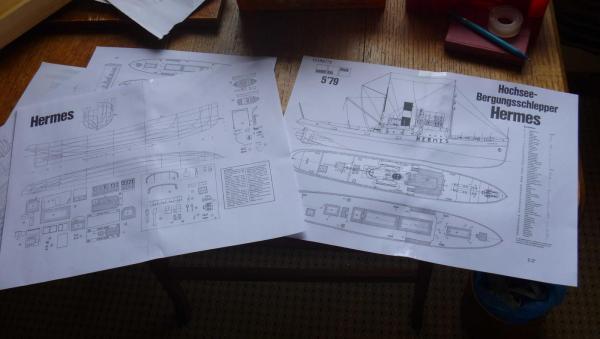
-
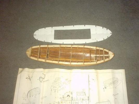
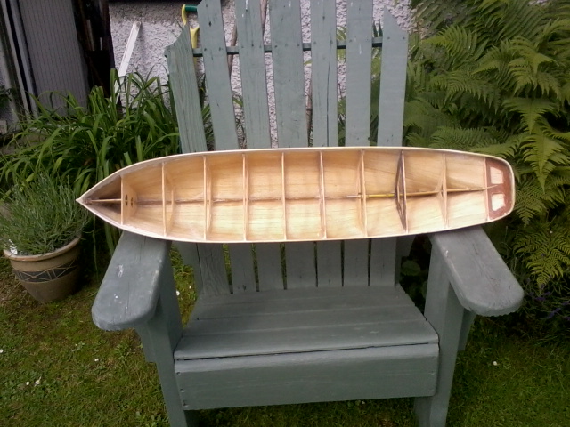
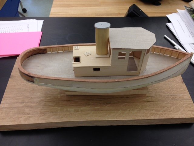
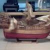 This Tugboat hull was given to me with a two-view sheet plan, started but never finished. I wanted to have a recovery vessel in case my RC sailboat capsized or got hung up in a lake or pond. A friend suggested it might be of use for that purpose. It will be a working RC boat, and specially re-designed for it's purpose. Pictures of hull and plan to follow when ready. The deck was badly deteriorated and poorly supported. I have torn all of it off down to a planked hull framework. I have started evening up and reinforcing the deck framework. This is its current condition. It has a slot through the keel for a prop shaft, and a place where a rudder would go behind the prop although it it will need to be framed for installation. The opening for the deck house should be okay now that it has been re-assembled and reinforced. Subdeck pattern Hull PLAN (All I have) Walter Biles