JohnE
-
Posts
309 -
Joined
-
Last visited
Recent Profile Visitors


-
 Scottish Guy reacted to a post in a topic:
For Beginners -- A Cautionary Tale
Scottish Guy reacted to a post in a topic:
For Beginners -- A Cautionary Tale
-
Rob S reacted to a post in a topic:
For Beginners -- A Cautionary Tale
-
jchbeiner reacted to a post in a topic:
French Frigate Things
-
druxey reacted to a post in a topic:
Seeking information on determining load waterline
-
PeteB reacted to a post in a topic:
74-gun ship by Gaetan Bordeleau - 1:24
-
Canute reacted to a post in a topic:
Swan class 3D model in progress
-
JohnE reacted to a post in a topic:
Ship paintings
-
JohnE reacted to a post in a topic:
Ship paintings
-
CaptainSteve reacted to a post in a topic:
Ship paintings
-
JohnE reacted to a post in a topic:
Licorne 1755 by mtaylor - 3/16" scale - French Frigate - from Hahn plans - Version 2.0 - TERMINATED
-
JohnE reacted to a post in a topic:
La Renommee 1744 by ChrisLBren - 1/48 Scale
-
Oh, yes Sir, you have been to sea and obviously love her as much as the ships. Your paintings are evocative and profoundly moving in many ways. Thank you for sharing them. You have created a new admirer and customer. I very like your appreciation of service craft and the oft neglected, lonesome and forlorn, patrol boats. My heart has a warm place for Castle class trawlers. John
-

Frégate la Cornélie 1795
JohnE replied to JohnE's topic in CAD and 3D Modelling/Drafting Plans with Software
Thanks all. Have to admit that I had some frustrating periods, but once the lights came on the journey became a lot of fun. Only wish I had known this sooner when poor Mark was having such problems with the stern of his Licorne. Herask and Bava are both encouraging me to get up to speed in Blender so I can do visualizations in 3D. They are really helping me focus the learning curve. The ability to see a complex piece of wood and how it fits with the other pieces, before I pull out the saw, will be I think invaluable. Ciao. John -
Hi Gaetan, I live on the Gulf coast in Alabama, so humidity changes are very large. It really messes with the guitars. I use a humidifier and a dehumidifier to keep things on a relatively even keel (ha, ha). I don't try to climate control, just keep the changes from being too radical. Might help le vaisseau. Love the work on the rablure. John
-
Frégate la Cornélie 1795
JohnE replied to JohnE's topic in CAD and 3D Modelling/Drafting Plans with Software
Something else that happened is I was able to import quarter-beam and mid-beam lines into the MATLAB hydro program and evaluate the curves for performance. Turns out that Jacques-Noël knew exactly what he was doing. They fall within acceptable modern parameters. Howard Chapelle and Merritt Edson would approve. It also becomes apparent why French ships (although can only speak to Sané types) were so sensitive to trim in order to get most out of their performance regime. The lines purty near say outright that if they have a bit too much load drag, or sailed with a squat, they will suffer and become sluggish, like a lovely lady on the arm of a boor. The kicker comes from Sané's famous 6 inch stretch after Villemaurin's sail trials in the historical Cornélie. Villemaurin noted stern trim sensitivity in great detail, load trimming both up and down, altering mast rake, and the sail suite. It told a lot to Sané. All of the stretch was put from Frame VII aft. Frame VII stayed where it was in the Venus (Hébé) and Virginie series. Frame VIII moved 3 inches farther aft from Frame VII and the aft perpendicular moved 3 inches farther back from Frame VIII. This centers the majority of the stretch smack dab in the region where the quarter buttock crosses the load waterline and stretches out the buttock lines in this area so they are considerably straighter. I was amazed at what a simple 6 inches could do, until I realized that the difference between the "right" design curves and my "wrong" ones were the matter one inch or less, back and forth, up or down. Whoda thunk? Wonder what Jacques-Noël would have done with access to a CAD program. I shiver to think. Ciao. John -
Frégate la Cornélie 1795
JohnE replied to JohnE's topic in CAD and 3D Modelling/Drafting Plans with Software
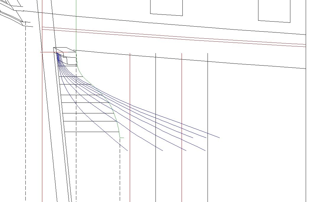
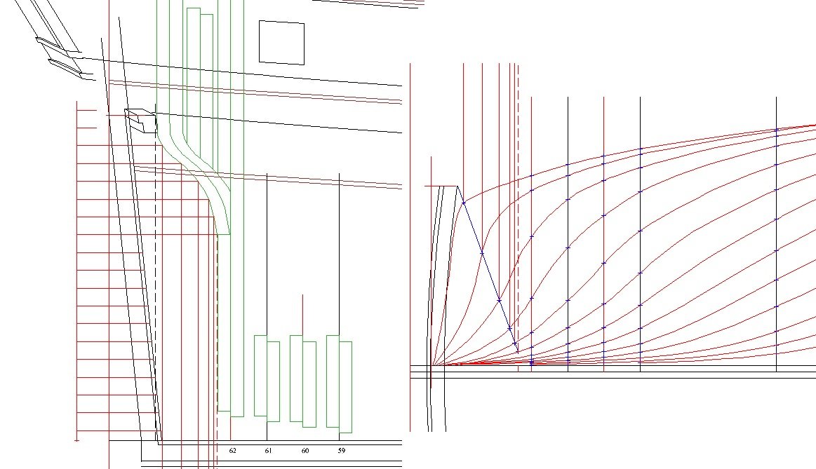
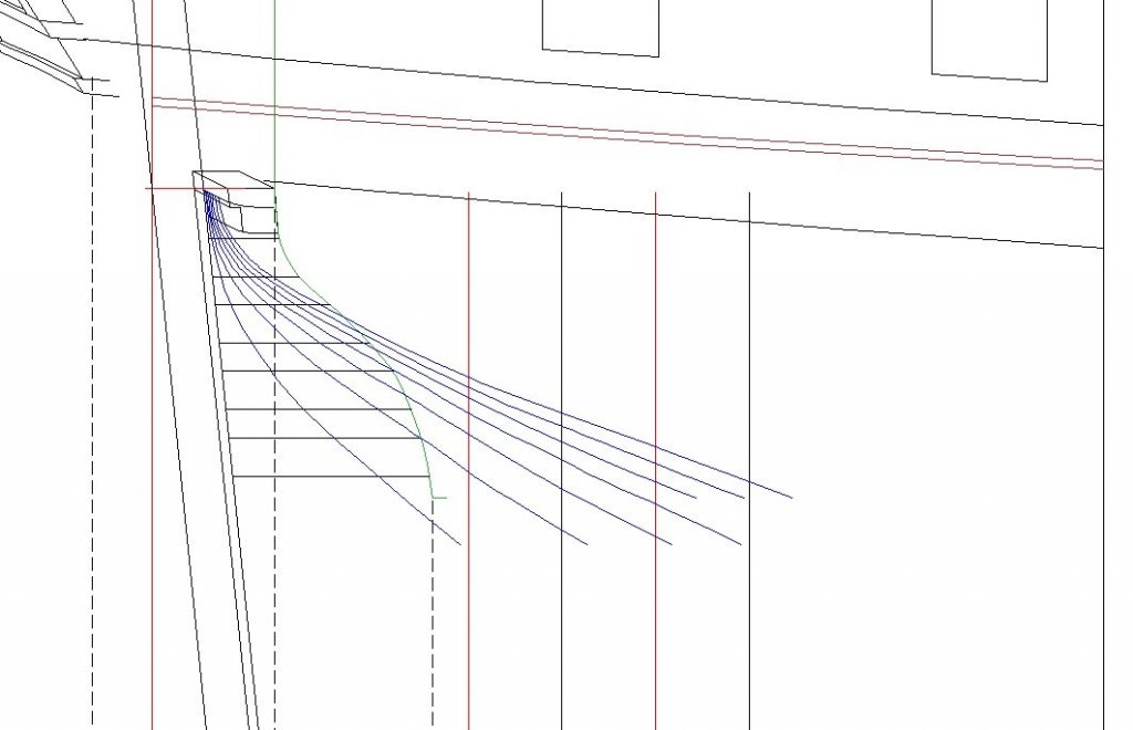
Thanks Druxey, that's nice to know. Speaking of translations ... had to do quite a bit of Vial du Clairbois for the lovely Cornélie. The compound curvatures of the fashion frame (estain) and the filling transoms have always been quite painful to get right. The main reason is no one has done those for a Sané design before, so there is nothing to use as a guide or make intelligent judgments from. The British didn't take off enough lines in the right places to provide a suitable guide, and even the lines in the Chaumont Papers are way too few and far-between, besides being completely unidentified. Woof! Everything was a guestimate, and wrong, as it turns out. I had to go back to the well. Vial has a section on this. Very informative, but superficial, and lacking in the very details that I needed for a proper understanding. Then I just happened to open Vol II. I had previously assumed Tome II was simply an 1805 retitling and reprint of Tome I with some additions. Wrogn again! I was fooled by the totally similar table of contents. Turns out that Tome II begins where Tome I leaves off. Seems that Tome I is the undergrad book having all the basics and sufficient gloss to get one started. Tome II, however, is the graduate level "design and construction theory" course book. Every section begins with the assumption you have Tome I open to the appropriate place and the Tome I drawings are at hand. Then it launches into detail ... thought I would have a heart attack! Woof! All right! Design the darn things from scratch! This is better than buttermilk pancakes! So I did. And it worked. And it didn't just work, the lines flowed directly into those of the well documented sections from Sané's devis. My estain was a bit off in body plan and profile views, and the waterlines and buttock/bow lines behind the estain needed considerable adjustment. Before, they were smooth, but arbitrary. Always subject to tweaking back-and-forth depending on which curve I started with - body, waterline, diagonal, ... Finally, after much sturm, drang und todesangst, I really think I have an understanding of French stern construction. Some pics. Waterlines (level lines) just flat look good. Not just that, but they grid out such that each level-line point projects right smack dab where it is supposed to on the profile buttocks and body plan, and arsey-versey. All this was the basis of the loft of the filling transoms. Easy peasy once the surface was completely defined.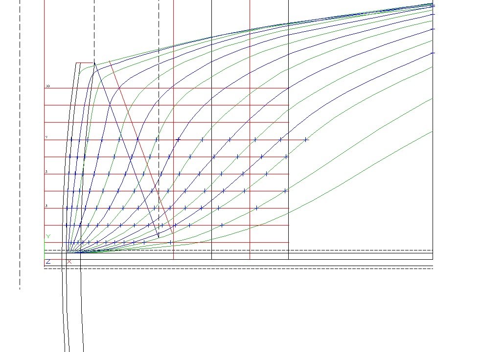
-
Swan class 3D model in progress
JohnE replied to dvm27's topic in CAD and 3D Modelling/Drafting Plans with Software
Wonderful pictures and outstanding work. Prekrasan !! ciao John- 104 replies
-
- 3
-
-
- pof swan series
- swan
- (and 1 more)
-
Frégate la Cornélie 1795
JohnE replied to JohnE's topic in CAD and 3D Modelling/Drafting Plans with Software
Unfortunately, no. The Mungo Murray treatise includes an abridgement of parts of Elemens de l'architectue navale by Duhamel du Monceau, but I think that's about it. So far as I know, Olivier, Ozanne, Morineau, Monceau, Forfait, Clairbois, Lescallier, even de Freminville, have not been translated except privately. John -
Frégate la Cornélie 1795
JohnE replied to JohnE's topic in CAD and 3D Modelling/Drafting Plans with Software
Hello Dan, French gammoning hole positions are often different from British practice. Boudriot mostly places his in the fill piece (garniture) between the cheek curves (courbes de jottereau) as you note. There is no 'rule' per se, and I have seen different designers position them in different places. Vial du Clairbois just says "make sure there is good purchase". It's no surprise that the French rig out different since their bowsprit steeve is 30 some degrees rather than the British 22 or so degrees, at least for frigates. Hope this helps. John -
Salut Gaetan I am doing exactly that for my Cornélie. I have the quille and contre-quille in 3D and am lofting each frame with special attention to the rabbet angles. It is interactive - I place a frame/couple and then tweak the keel assembly underneath it to reflect a proper shape to receive the garboard strake. It is fun and interesting to watch the rabbet shape evolve as I move farther and farther aft. When the process is finished, I will have a set of suitable plans for the keel pieces, as well as lofted frames/couples that fit. 3D is a bit of a challenge, but a great deal of fun. If you enjoy drafting plans and figuring out fiddly-bit details, 3D is a rewarding exercise. John
-
Frégate la Cornélie 1795
JohnE replied to JohnE's topic in CAD and 3D Modelling/Drafting Plans with Software
Thanks for the likes. I was a bit remiss and forgot to put up some pics. Here's some of the guidelines for the lofting. This part makes sure that the lines are ok in all three views and everything checks against the Devis. There are a (very) few places where the Devis is inconsistent by a (very) small amount, but they are all in the fiddly-bits category. All things considered, she's coming along beautifully; everything is falling right into place. That means it's time to be extra careful so I don't get bit in the Coulomb.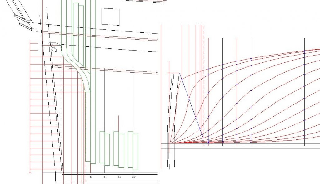
-
Frégate la Cornélie 1795
JohnE replied to JohnE's topic in CAD and 3D Modelling/Drafting Plans with Software
The stern lofting of Cornélie is pretty well finished and golly, does she have lovely looking buttocks. Fashion frame(s) and filling transoms fair in nicely and the surface differentials, for defining the wood’s shape and curve, are complete. The remaining step is to position it all on the massif and define the pieces of the deadwood, and their curvatures. Whew! That was hard! Well, not so much hard as incredibly painstaking. I got inspired by the 3D work done for the Swan Group by their European mystery guest. I am trying some of the same techniques to get rabbets looking right and get good plots of cutting-down lines, etc.. The goal is to have the plan set that includes a synthesis of benchmark lines representing both French and British practice. Much of what people are used to seeing on British plans seems to be missing somehow from the French equivalent. However, it is probably better to say that certain information is not necessarily missing, but is rather presented in a completely different manner. So why not combine the two? CAD is so cool! -
The idea of French frigates, and ships in general, being ‘better’ than others was true to a large extent at a certain period in time. The development of French warship technology and construction dates back to the mercantilist policies initiated by Richelieu and mastered by Colbert, with much of the increased state revenues going into development of the Navy, including development of the dockyards, schools, manpower base, and other infrastructure. Colbert’s bureaucratic system allowed France to pursue technological advances in ship construction and maritime science, helped along no doubt by the burgeoning influence of the Academie Royale des Sciences and the dramatic revolutions in the sciences engendered by the Enlightenment. This institutionalization of French shipbuilding, and subsequent professionalism of the shipbuilding industry, promoted uniform understanding and dissemination of technical improvements throughout the Naval establishment. In short, the immersion into the scientific principles of vessel motion and hull form led to led to the development of a new ‘model’ for French warships (Paul Hoste, Théorie de la Construction des Vaisseaux, 1697). They were considerably longer and broader than contemporary British or Dutch ships, but even with increased beam, they had a larger length/beam ratio. Modern naval architecture recognizes the importance of Lwl and L/B in determining vessel performance, especially speed. Indeed, the development of the science of metastability, and its calculation, resulted in the desire to find the optimum L/B ratio for vessels of various sizes and functions; too narrow a beam resulted in poor initial stability, a very tender sailing vessel, and inability to carry armament. Too wide a beam resulted in the increase of drag resistance and very poor performance with the breeze far forward or far aft (beating and running). In short, they “wallowed like pigs’. For the most part, the French Navy, under the Naval Ordinance of 1689, was the envy and touchstone of Naval establishments the world over. This obtained until about 1765, when the neglect imposed by the Seven Years War, and the consequent exhaustion of finances took hold with a vengeance. There was a brief interlude under Gabriel de Choiseul, and a second under Gabriel de la Croix de Castries, but in the later third of the eighteenth century, the French naval establishment suffered, perhaps most of all, from the pervasive bureaucratic retrenchment into irresolution, conservatism, and self perpetuation, affecting the State in general. Although many incremental advances were made, the state of revolutionary (and evolutionary) innovation languished. By this time, Britain, the Netherlands, Denmark, Spain, etc.. had caught up. Britain established its own scientific, academic, and bureaucratic infrastructure, learning from the experience and success of the French. They were certainly not above deconstructing notable captured vessels, right down to counting the bolts, and learning as much as possible about how ‘the other guy does it’, but by the last decade of the century she had grasped and internalized all the essentials of design and construction for performance. France still had the vestigial reputation, and her ships were admittedly fast and elegant. However, given the divergence of French and British naval doctrine, and British adherence to scientific principles of design and construction, French vessels were no longer the ‘best’, or even ‘better’, for British imperitives. This is a very thin and superficial gloss on the subject, and I apologize to those already familiar with its intricacies, for the amount of abstraction. There is room for several books, on several individual subjects, in this brief. Hopefully someone will find their muse and be moved to write one. John
-
Frégate la Cornélie 1795
JohnE replied to JohnE's topic in CAD and 3D Modelling/Drafting Plans with Software
More progress. The spine is pretty well settled in; keel, bow, stern, deadwood. To finalize things, I had to make an executive decision on the sided dimensions of frames/couples. Room and space is a simple calculation; station spacing is 101 pouces, there are three filling couples per station (except extreme forward and aft), so room and space is 25 pouces, 3 lignes. All I had to do was determine the frame siding. The kinda, sorta, "rule" from the echantillon is 9 pouce 6 lignes. However, this does not correspond with measurements taken by the British off captured Sané frigates. The majority of frames measured out at 9 1/2" which converts to 9 pouces. At least one vessel, albeit built in Venice, had frames sided 9" which is a skoosh less than 8 pouces 6 lignes. Everyone agreed that the Venetian vessel was lightly built and notably departed from the French standard. So is typical frame siding 9 pouces, or 9 pouces 6 lignes? Well, I split the difference. Frame siding is 9 pouces 3 lignes, giving a couple siding of 18 pouces 6 lignes, and a spacing of 6 pouces 9 lignes. It is basically a 13.5mm departure from the "rule" at full scale. Anyway, that's the story. Next on the do list is loft the hawse and bollard timbers. That will finish l'Etrave. Last is loft the stern assembly. I am marshaling all the curses I can find in every language I have ever heard of, since I know that the infamous compound curvatures of the fashion frame and filling transoms are waiting to bite me in the butt, again, and I need to be prepared. Ciao. John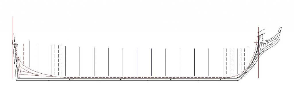
-
Hello Gaetan, I think the drain notch should go all the way forward and aft. Connect all the frames/couples that have space between them, including crotches on deadwood and apron. Ship has a pitching motion, and if there is water above the floorboards amidships, it will slosh forward when the ship pitches down, and slosh aft when the ship pitches up. It seems a good idea to drain away water from the space between crotches if (or when) it collects there from sloshing. This may not be necessary in normal cases, but sometimes leaks can be rather large and let in a bunch of water. Ciao. John
-
Me too, Mark. Have some catching up to do. It's a bee-you-tee-ful summer day here on the gulf coast, 90+ degrees with 90+ % humidity. Can't wait to see the interior planking. Stay well. John