
jpalmer1970
-
Posts
318 -
Joined
-
Last visited
1 Follower

About jpalmer1970

Recent Profile Visitors
1,251 profile views


-
 Scottish Guy reacted to a post in a topic:
Helping hands vice
Scottish Guy reacted to a post in a topic:
Helping hands vice
-
jpalmer1970 reacted to a post in a topic:
HMS Mercury 1779 by Mr Pleasant - 1:64 - based on Shipyard paper model
-
Frank Burroughs reacted to a post in a topic:
Helping hands vice
-
jpalmer1970 reacted to a post in a topic:
1:80 Endeavour – America’s Cup 1934 - Amati
-
 jpalmer1970 reacted to a post in a topic:
Helping hands vice
jpalmer1970 reacted to a post in a topic:
Helping hands vice
-
That's a good tactic! I might have to try that out myself. 😀
-
 jpalmer1970 reacted to a post in a topic:
The Hayling Hoy by jpalmer1970 - 1:48 scale - First POF build
jpalmer1970 reacted to a post in a topic:
The Hayling Hoy by jpalmer1970 - 1:48 scale - First POF build
-
 Many thanks Druxey! That is very helpful. It is a much simple solution than I had imagined. I was obviously over complicating it due to not understanding the various lines representing the shape of the transom, so thanks also for pointing out how they represent the curved nature of that piece.
 -
mtaylor reacted to a post in a topic:
The Hayling Hoy by jpalmer1970 - 1:48 scale - First POF build
-
mtaylor reacted to a post in a topic:
The Hayling Hoy by jpalmer1970 - 1:48 scale - First POF build
-
Thanks for this Brian. The exploded view is very helpful in understanding how all of these pieces connect. I'm puzzled as to the actual shape of the top of the inner post on my plans but I'll look at them again and see if this helps.
-
Thukydides reacted to a post in a topic:
The Hayling Hoy by jpalmer1970 - 1:48 scale - First POF build
-
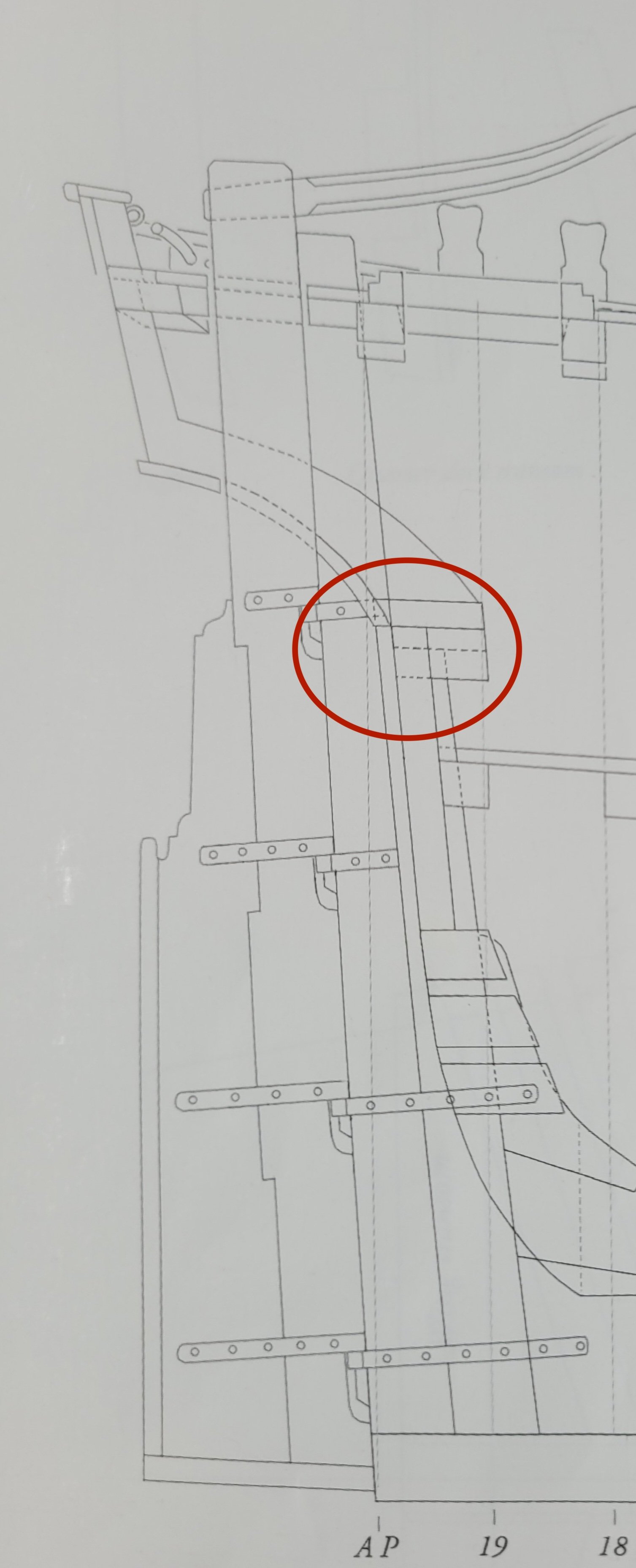
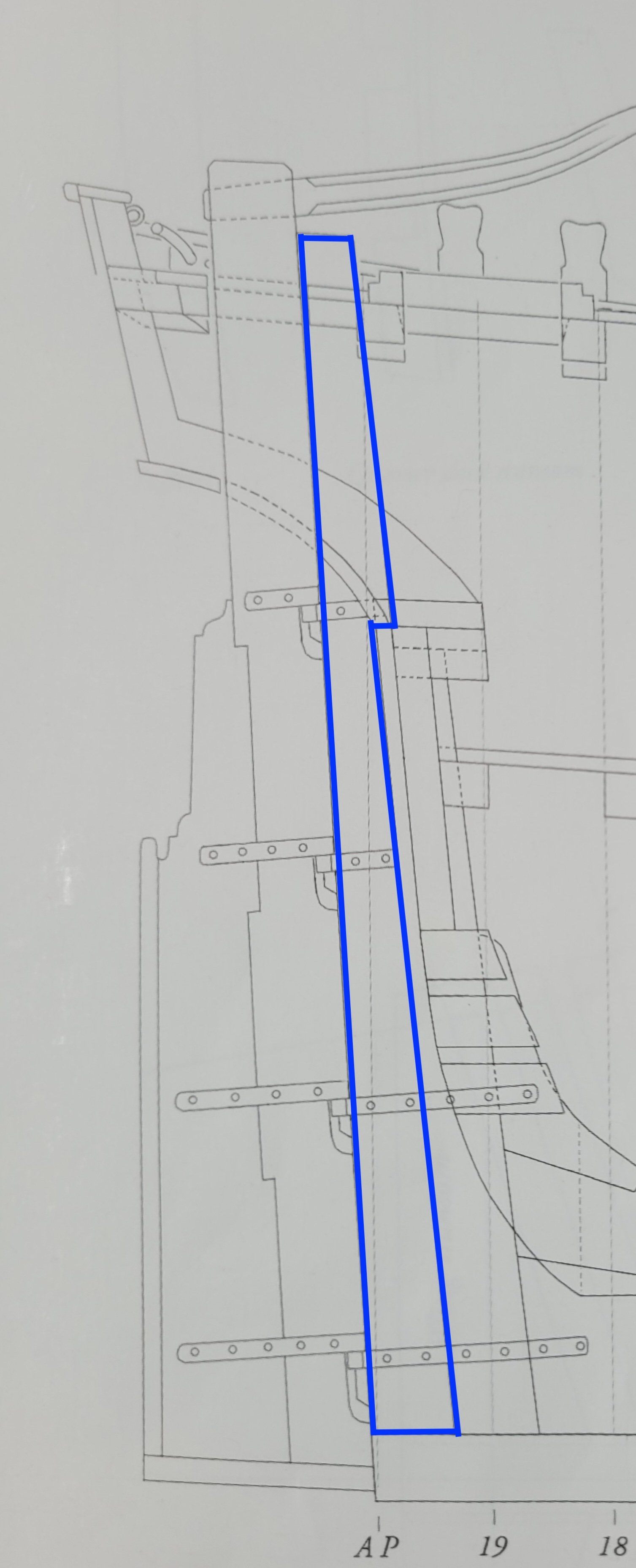
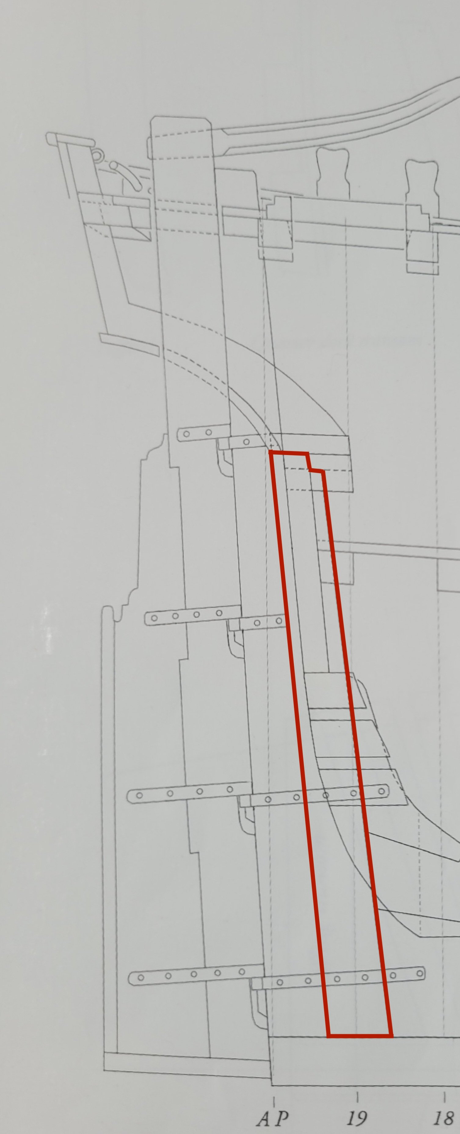
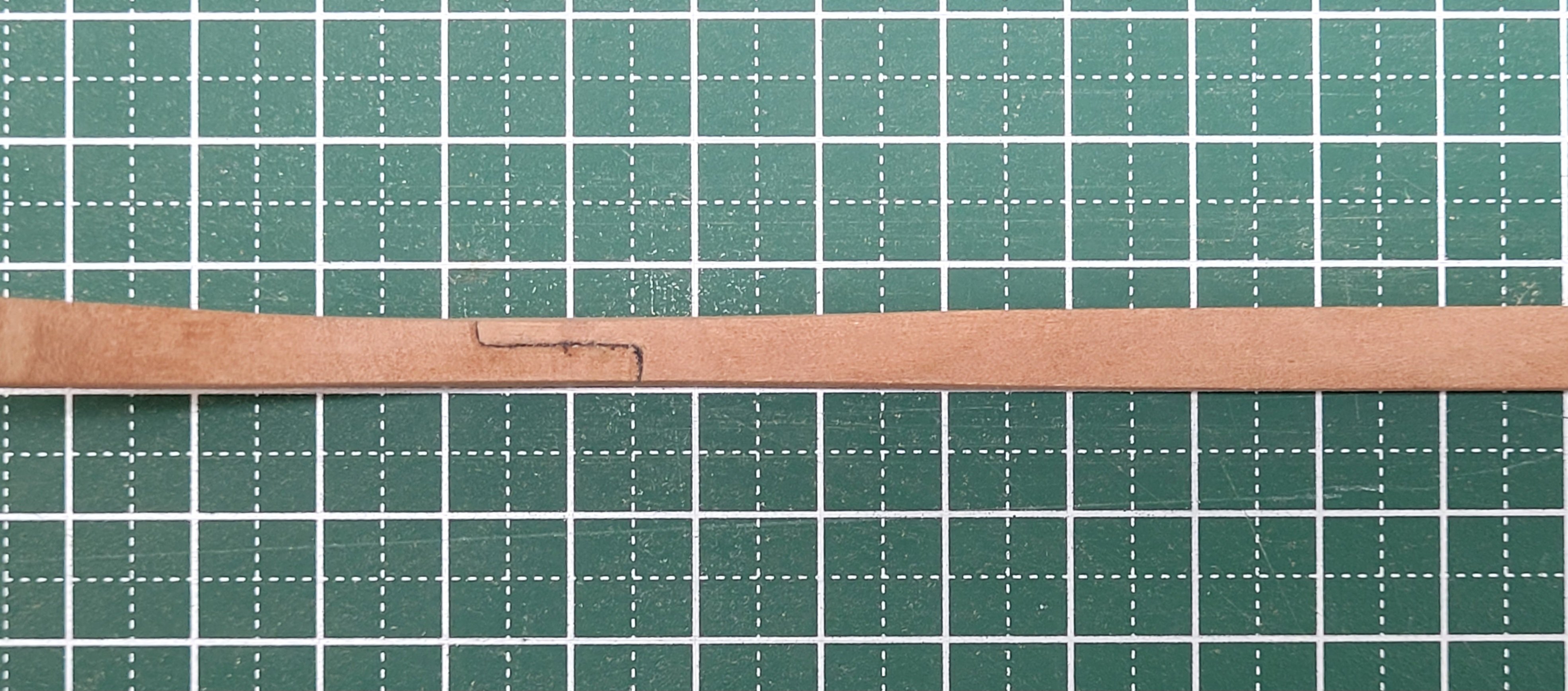
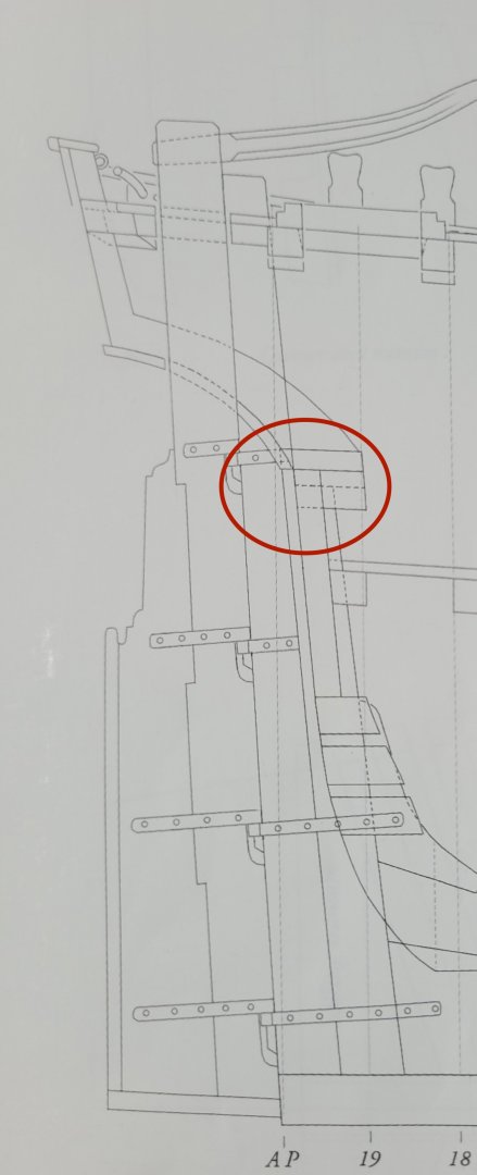
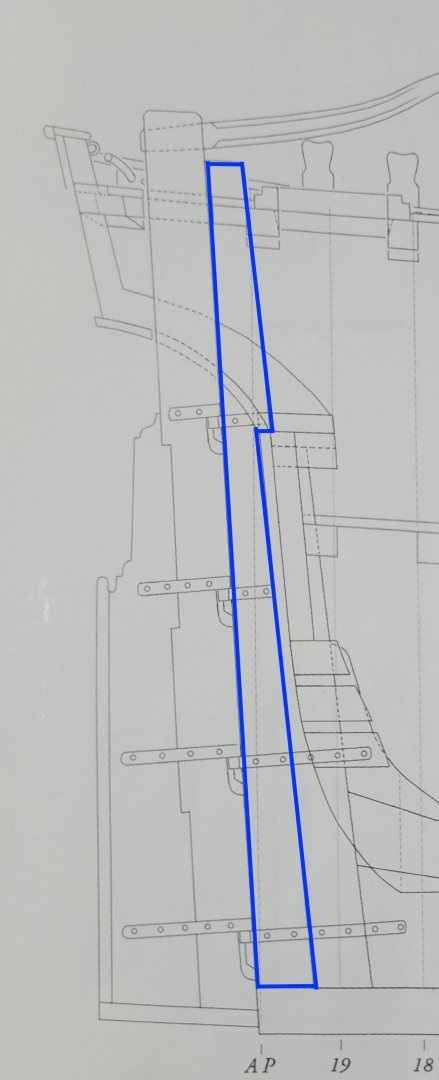
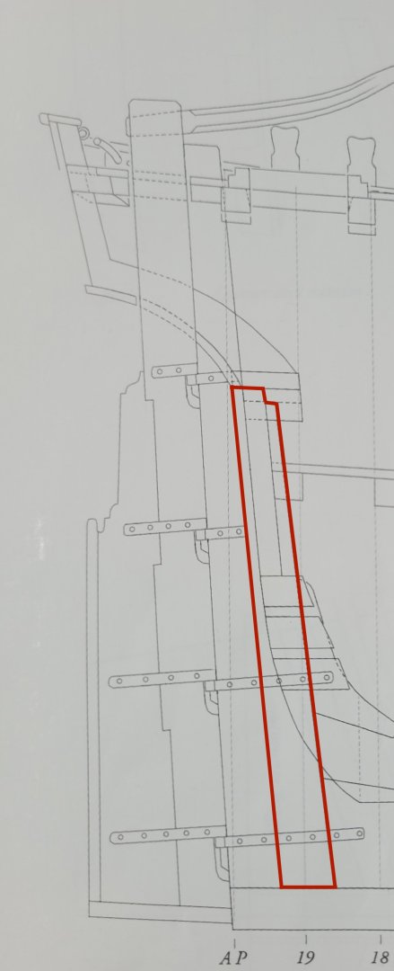
Hi folks, I have been puzzling over the plans looking at the sternpost and the inner post and I'm having a bit if difficulty understanding how they are shaped where they meet up with the wing transom. This part of the plan has lots of lines for all of these various parts and I'm not sure sure which one is which! Here is a scan of part of the plan and it is this area in the red oval that I am struggling with. The sternpost shape is, I hope fairly obvious, and I have marked it in blue in the scan below. It appears to me to have a little 'hook' where it sits on top of the top of the inner post which is where the rabbet ends I believe. Is that correct, do you think? It is the shape of the top of the inner post that is confusing me the most as it appears that this is where the wing transom sits. I have marked out what I think is the correct shape in red below but looking at the illustrations in David's book the top of his sternpost seems to be complete flat, rather than having that little step? I fear I am missing something here and hopefully that may be obvious to more of you than it is to me! Any advice and guidance would be most welcome as I would like to get theses pieces cut out of the stock. I thought I had it all sussed out originally but the more I look at them now the more confused I get - so some fresh perspectives from you all will certainly help. Many thanks in advance 🙏
-
JpR62 reacted to a post in a topic:
The Hayling Hoy by jpalmer1970 - 1:48 scale - First POF build
-
brunnels reacted to a post in a topic:
HM Cutter Alert by Thukydides - Vanguard Models - 1:64 - first build
-
Glen McGuire reacted to a post in a topic:
HM Cutter Alert by Thukydides - Vanguard Models - 1:64 - first build
-
AON reacted to a post in a topic:
HM Cutter Alert by Thukydides - Vanguard Models - 1:64 - first build
-
CiscoH reacted to a post in a topic:
HM Cutter Alert by Thukydides - Vanguard Models - 1:64 - first build
-
Excellent work! Your attention to detail is certainly paying off here.
- 479 replies
-
- 5
-
-
-
-
- vanguard models
- alert
- (and 1 more)
-
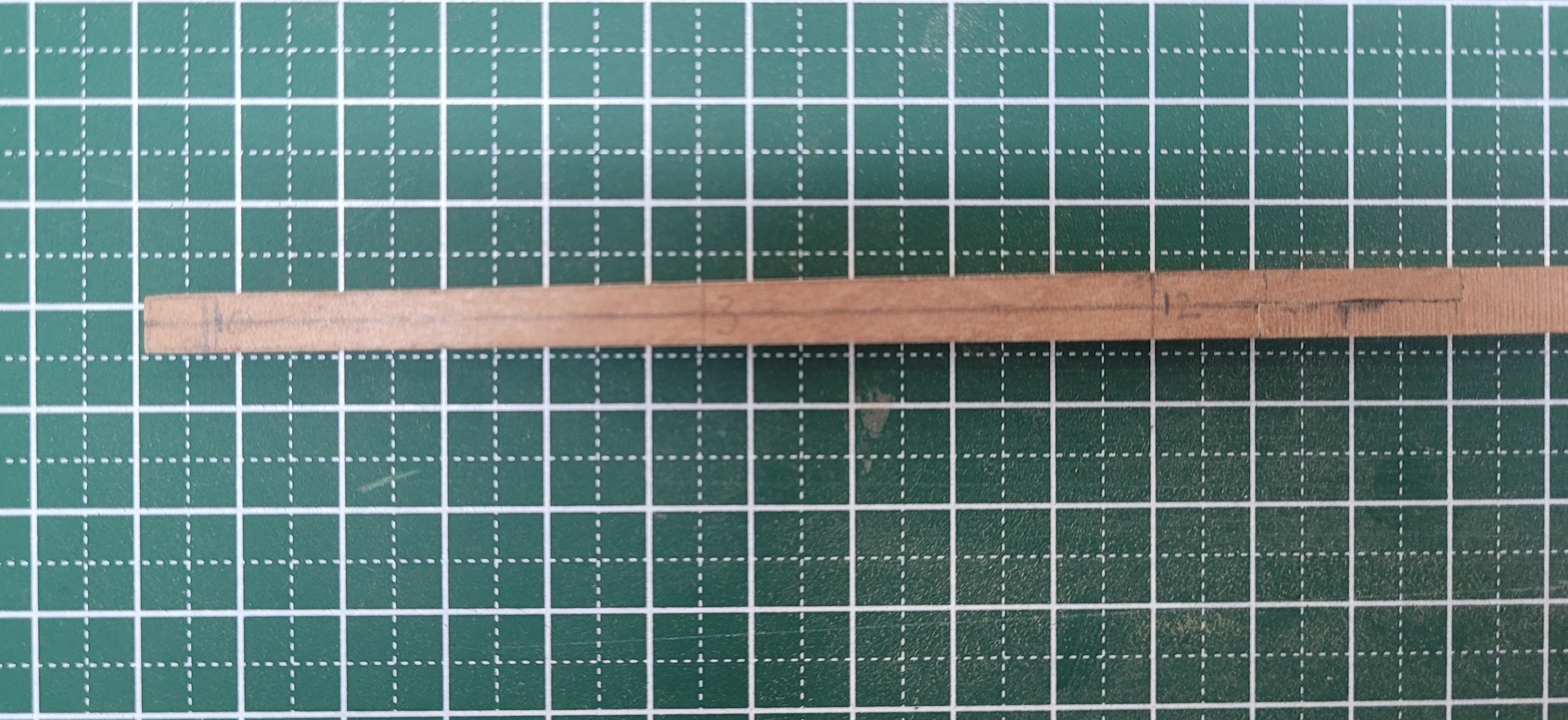
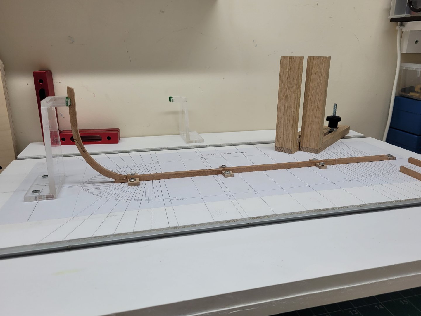
Just a brief update on the latest work on the keel and stem. The rear of the keel tapers in width from 12" to 10" and so this was sanded to size. I also drilled the scarph joint with a #75 drill and used 24 gauge copper wire as bolts. The stem was glued to the front section of the keel at the boxing joint. The front of the keel and the lower part of the stem also taper in width from 12" to 10" and so this was also sanded to size before the boxing joint bolts were added. At present I haven't glued the forward section of the keel to the rear two pieces as I feel it might be easier to have the keel in two parts whilst I am shaping and fitting the other pieces which fit to it, such as the stepson and the deadwood etc. I am less likely to knock it and damage it if it is in two smaller parts rather than one longer piece. Finally at this stage I fixed the acrylic stem mount to the board.

-
Many thanks, Greg. I must admit I hadn't given any consideration to either of those points about the tissue paper so I am glad you raised those questions! I did some further tests today and I'm pleased to say that the tissue paper I have seems to be colourfast - I didn't have any problems with it either in debonding a join with isotropy alcohol or with adding a coating of wipe on poly, so it looks as though I was lucky 😀
-
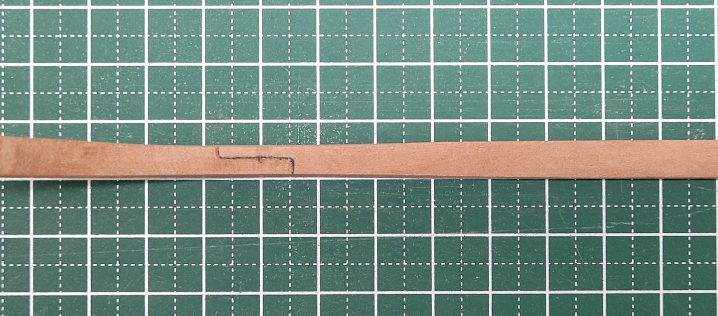
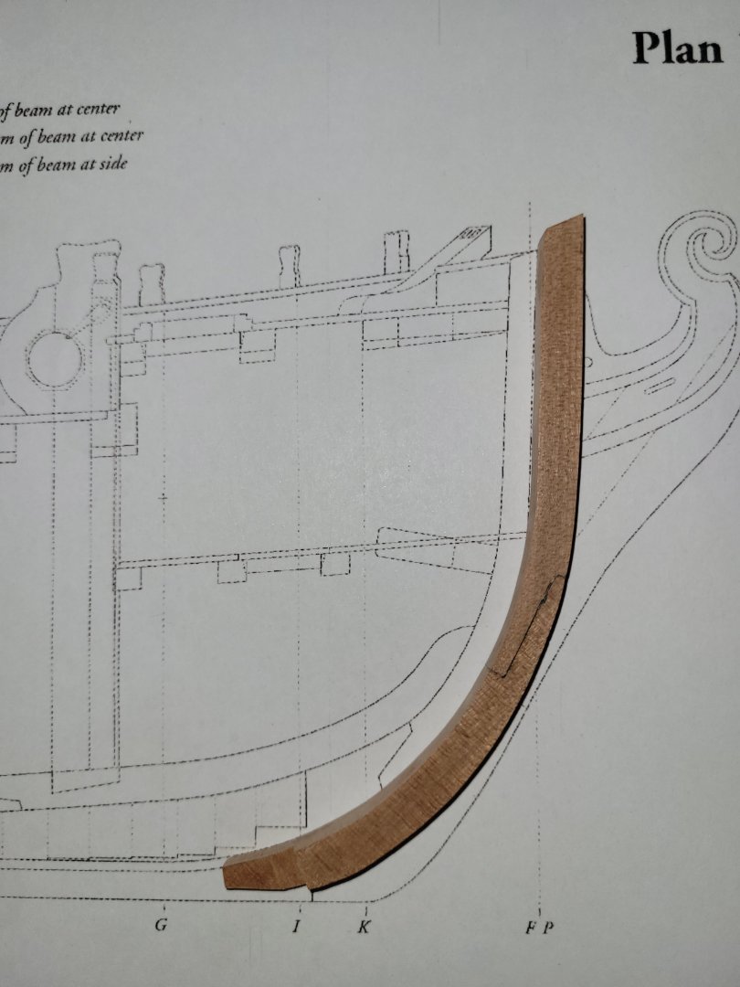
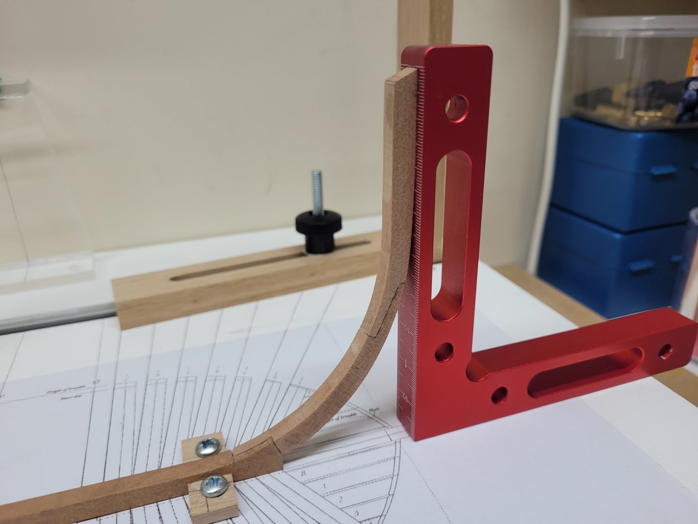
I spent a little time this week experimenting with different ways to represent the tarred joints in the keel. I made up some test scarph joint pieces and tried out some of the alternate ways mentioned recently in Pirate Adam's log - black tissue paper, #2B pencil, #5B pencil and dark paint either mixed in the glue or just added to the edges of the joint. The #5B pencil seemed to smudge very easily and I also struggled with the paint option - perhaps I used too much but it just seemed to stain the sides of the join very easily, though I am sure it could easily be cleaned up. The #2B pencil and the black tissue paper both worked well and I felt that given the reddish hue of the myrtle, the tissue paper option seemed to present a cleaner and more defined joint, so that is what I have decided to proceed with. I continued working on the lower stem piece gradually refining the shape so that it matched the plan on both the inside and the outside curve. The upper stem was them mostly shaped to size and then glued to the lower stem with a tissue paper lining to the join. The upper stem was then shaped to blend in with the curve of the lower stem. It seems like a really small achievement but I was very pleased to get these two pieces together and have them both match the shape on the plan - I can at least say now I am building the model, rather than just cutting wood into small pieces! 😀 Here is the joined stem - I still need to add some copper bolts to the joint and then taper the lower section to shape once it has been attached to the keel at the boxing joint. Both the forward and aft ends of the keel taper from 12" to 10". And here it is just sitting against the boxing joint in the keel to see if I have all the angles correct.
- 32 replies
-
- 16
-
-
Welcome to MSW !! 👍
-
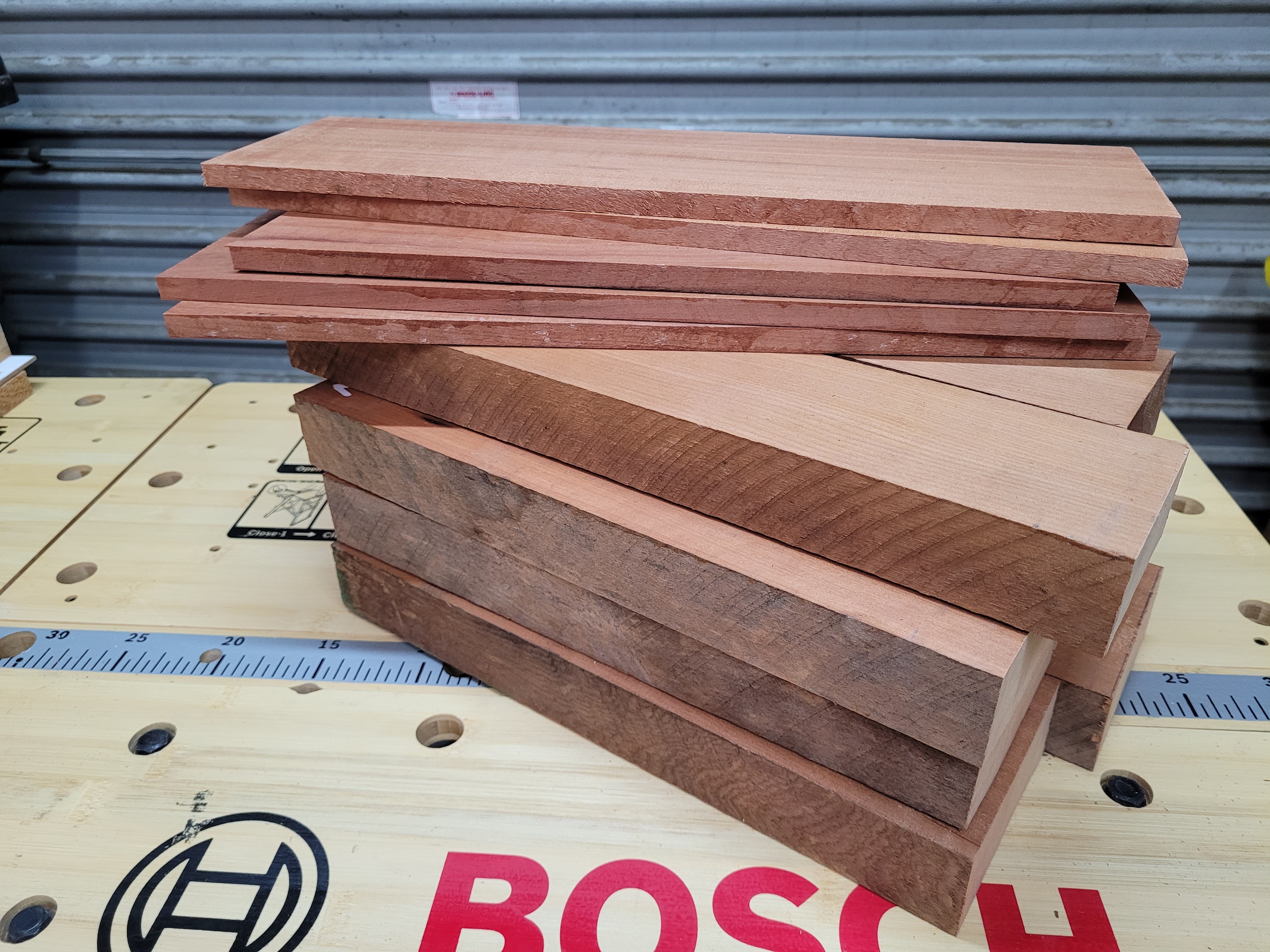
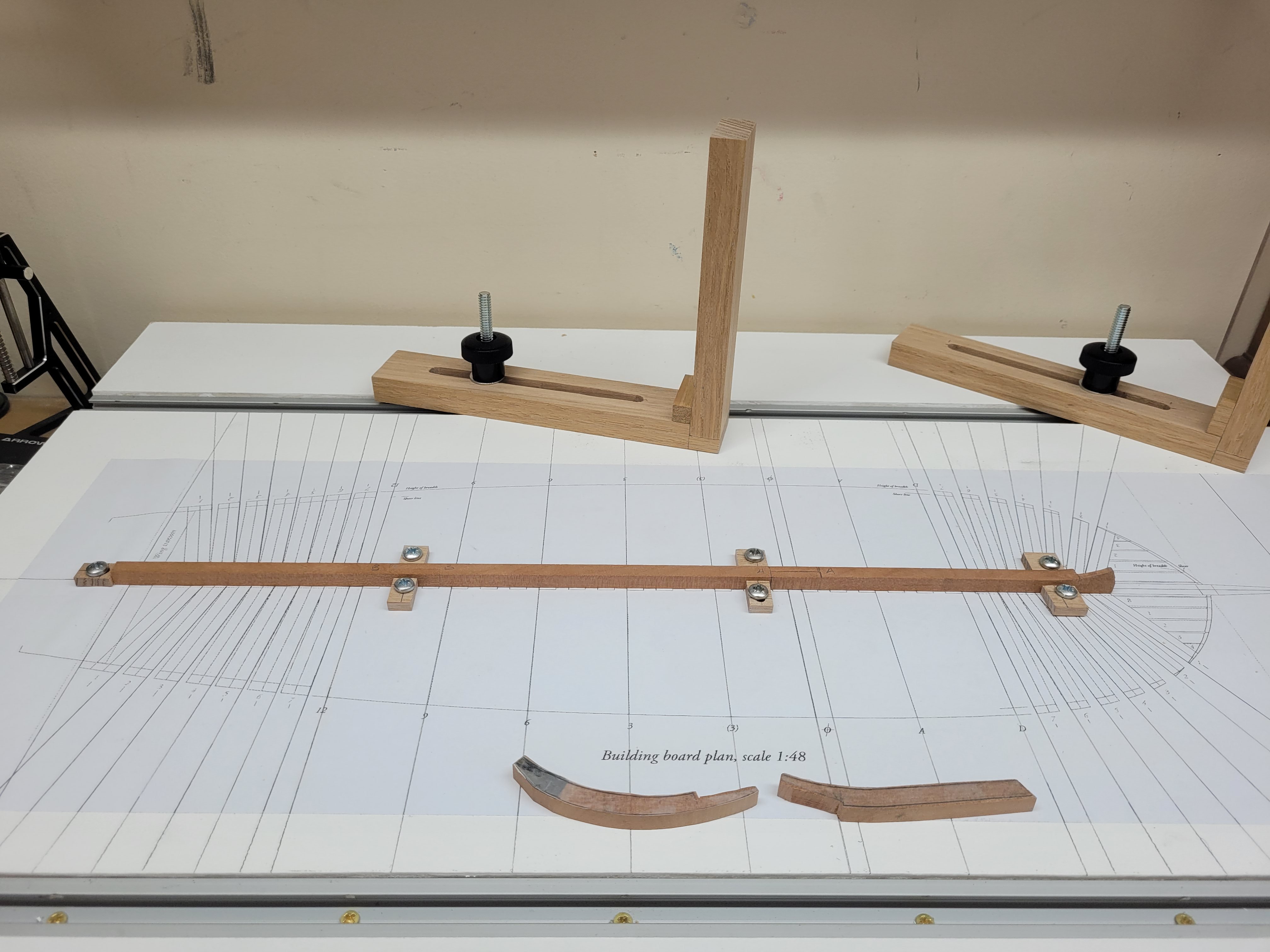
Just a small update on the latest work. I firstly purchased some more Australian myrtle from my local supplier - some thinner 10mm sheets and some 45mm deep pieces. Hopefully this stash will keep me going for quite some time. I haven't yet worked out exactly how much wood I need for the frames etc but I plan to have a look at that at some point in the coming weeks. I also continued working on the keel and stem pieces. The lower and upper stem pieces were cut out of the 12" stock. I actually had to make another lower stem after some wayward sanding of the first attempt but I have now managed to get the two stem pieces to fit together nicely. I shaped the lower stem boxing joint and so far everything seems to be lining up well but I do need to cut out the recess on it for it to fit against the keel. I realised after the fact that it would probably have been easier to make the joint on the lower stem first and use that as a template with which to cut out the boxing joint on the keel, rather than the other way around - but that is one of the learning experiences. I also cut the three keel sections to length and made the forward scarph joint. I cut this scarph with the table saw and may have gone a hair too deep with my cut but I will need to wait until I decide on how I am going to line the joints to see if it was too much. Tissue paper or thin paper may be enough to 'pad' out the joint perhaps. it won't be noticeable from the side of the keel but I do need to ensure that the joint is strongly glued. I have been reading the discussion on how to simulate the effect of the tarred joints in @Pirate adam's build log of the Crocodile and so i will experiment with the various methods suggested there. As the myrtle has a reddish hue I think a black joint may provide more contrast than a brown one but we will see. Finally it was good to actually put the keel pieces onto the building board so that it looks like I have made som progress 😀. Nothing is glued or fixed at all so far as there is still much more to do to the keel in the coming weeks.


- 32 replies
-
- 12
-
-
It is interesting to see how Occre want you to progress with this planking and shaping of the bow. Most kits have some sort of central false keel and bulkheads going all the way to the bow into which you might add filler blocks, but I have never seen this before where the first planking terminates well before the bow and the bow section is instead carved from blocks. Endeavour is a very bluff bowed ship and so perhaps that is the reason for this? Good luck and I'm interested to see how it turns out. 👍
-
OUTSTANDING Mini Drill
jpalmer1970 replied to Bill Jackson's topic in Modeling tools and Workshop Equipment
I have one of these and find it much more useful than a dremel for drilling small holes for eyebolts etc. The slower speed compared to the usual rotary tools (500rpm versus 5000+ rpm) and the small size of the unit allows for more accuracy I think. The drill press is also useful on occasion depending upon what you need to do - I seem to be terrible at drilling straight by hand.... It is basically a motorised pin vise, and not a cheap one at that, but still useful for me.