James H
-
Posts
6,139 -
Joined
-
Last visited
Content Type
Profiles
Forums
Gallery
Events
Everything posted by James H
-
 It’s looking to be a Level 3 ‘Experienced’ but that is mostly due to rig. The hull itself would be a level lower, but we have to factor in the rig.
- 76 replies
-
- 9
-

-
- Harpy
- Vanguard Models
- (and 1 more)
-
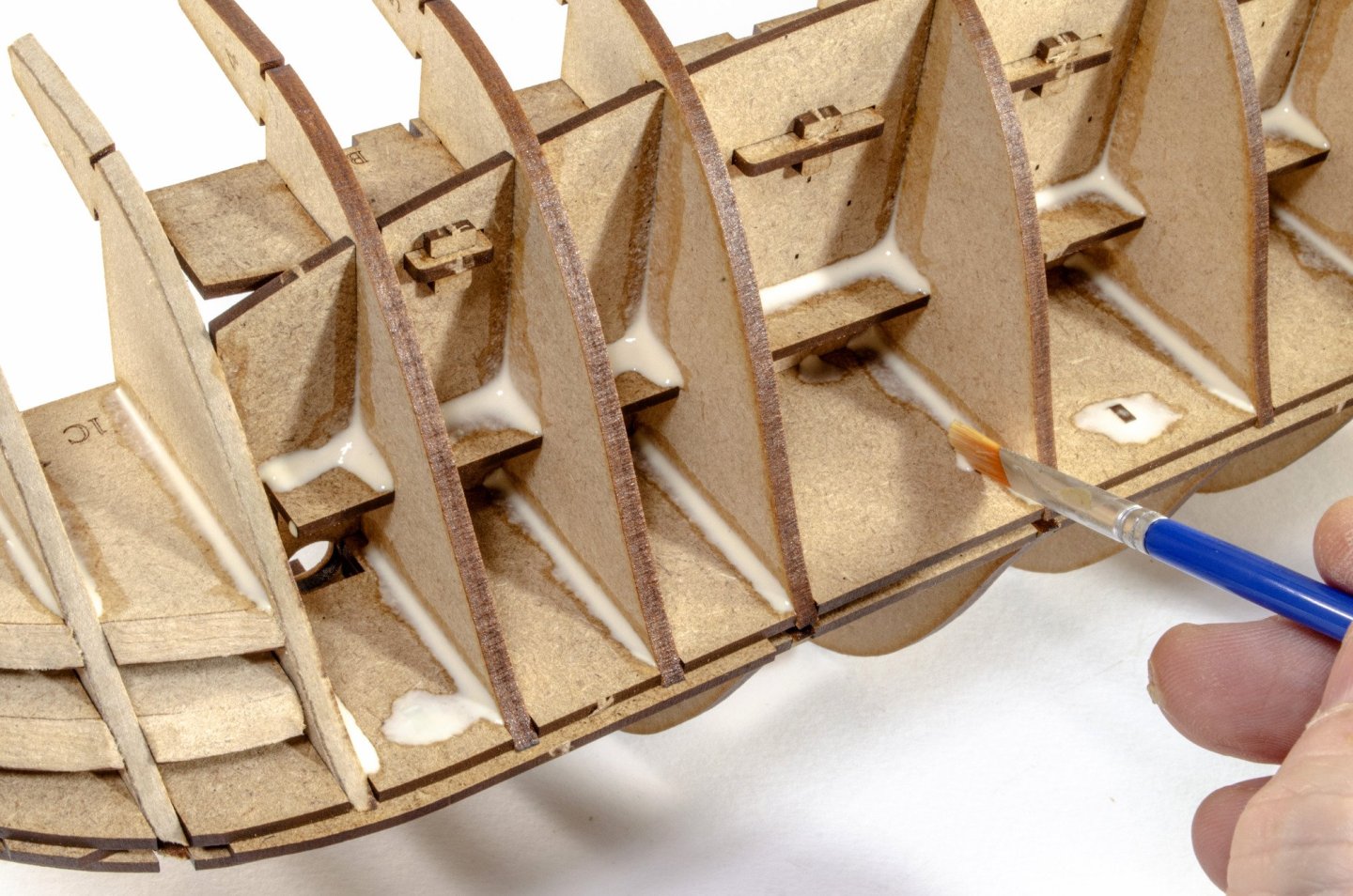
Don't apply glue to the bulkhead ears. It will be a nightmare to remove those ears later and will make an unholy mess...as well as pull chunks from the bulwarks. Only apply glue along the deck height (lowest deck line) and to where the lower bulkheads are. Alternatively, you can dry clamp everything and then brush the glue in carefully and sparingly along deck height (keeping away from the bulkhead ears) and also from underneath into where the bulwark and bulkheads meet.
- 177 replies
-
- 6
-
-
- Sherbourne
- vanguard models
- (and 3 more)
-
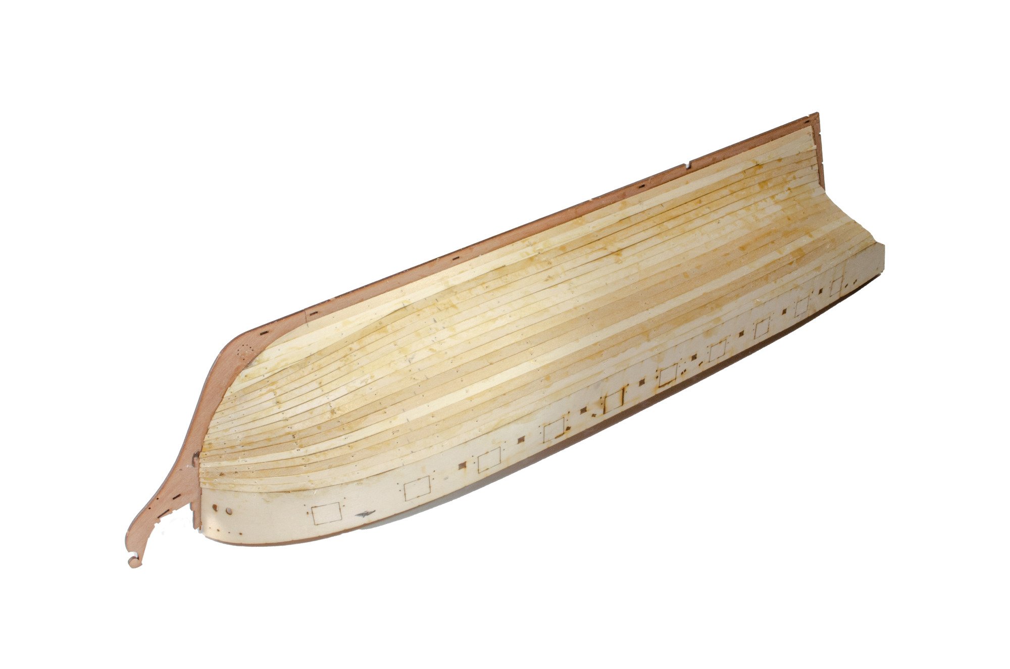
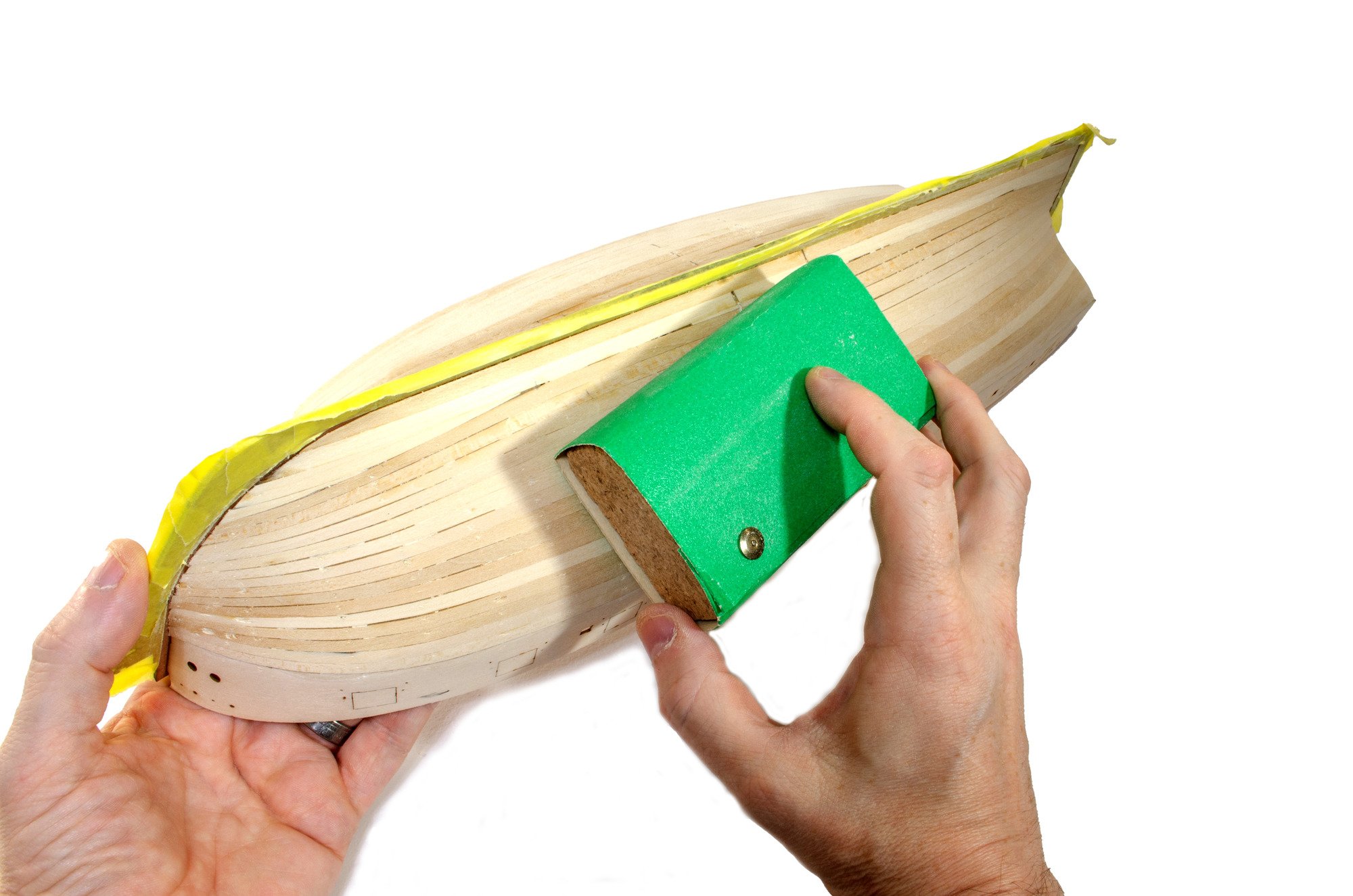
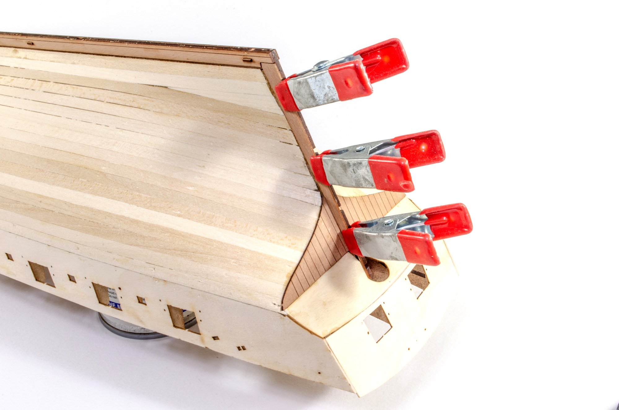
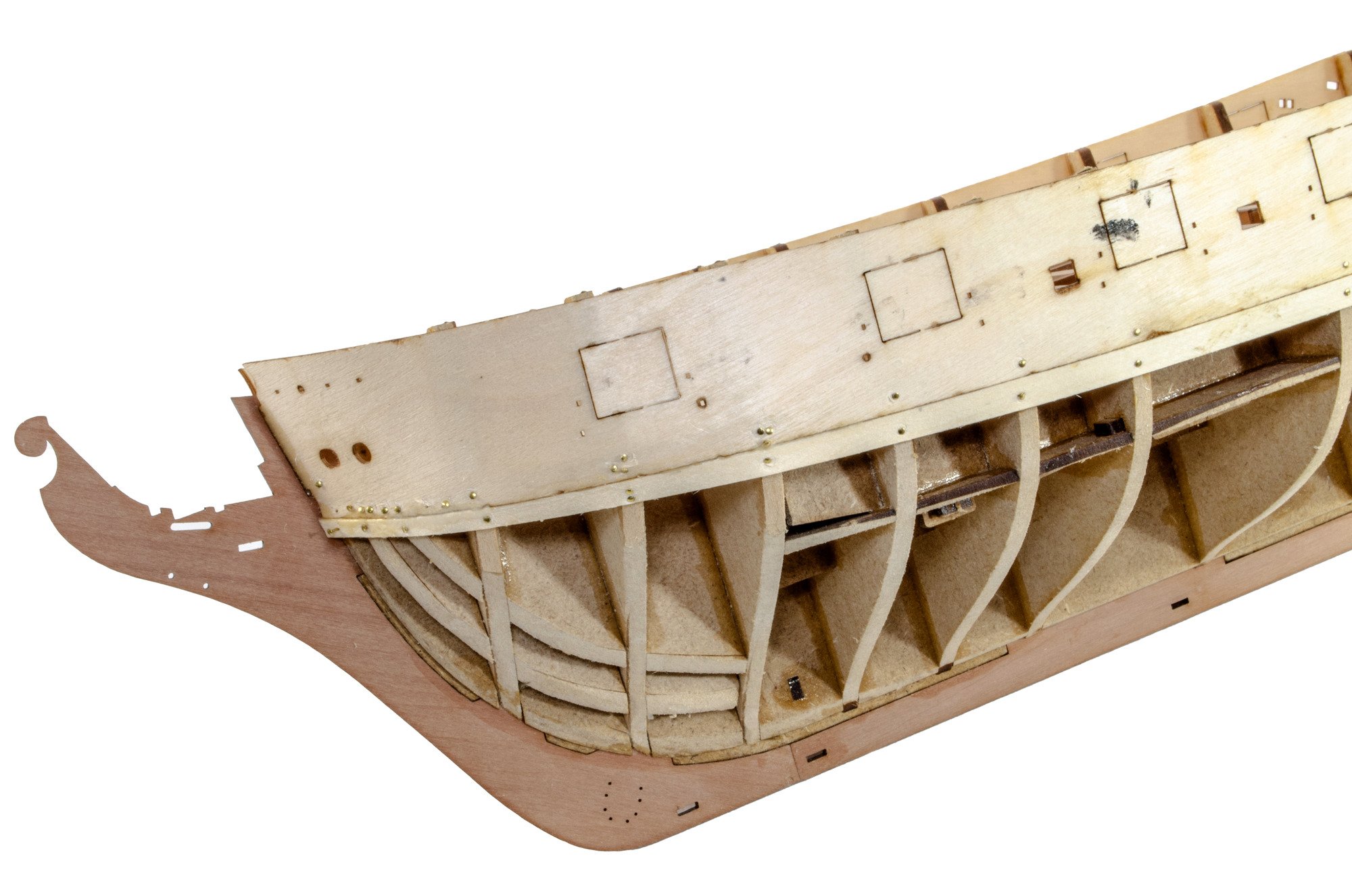
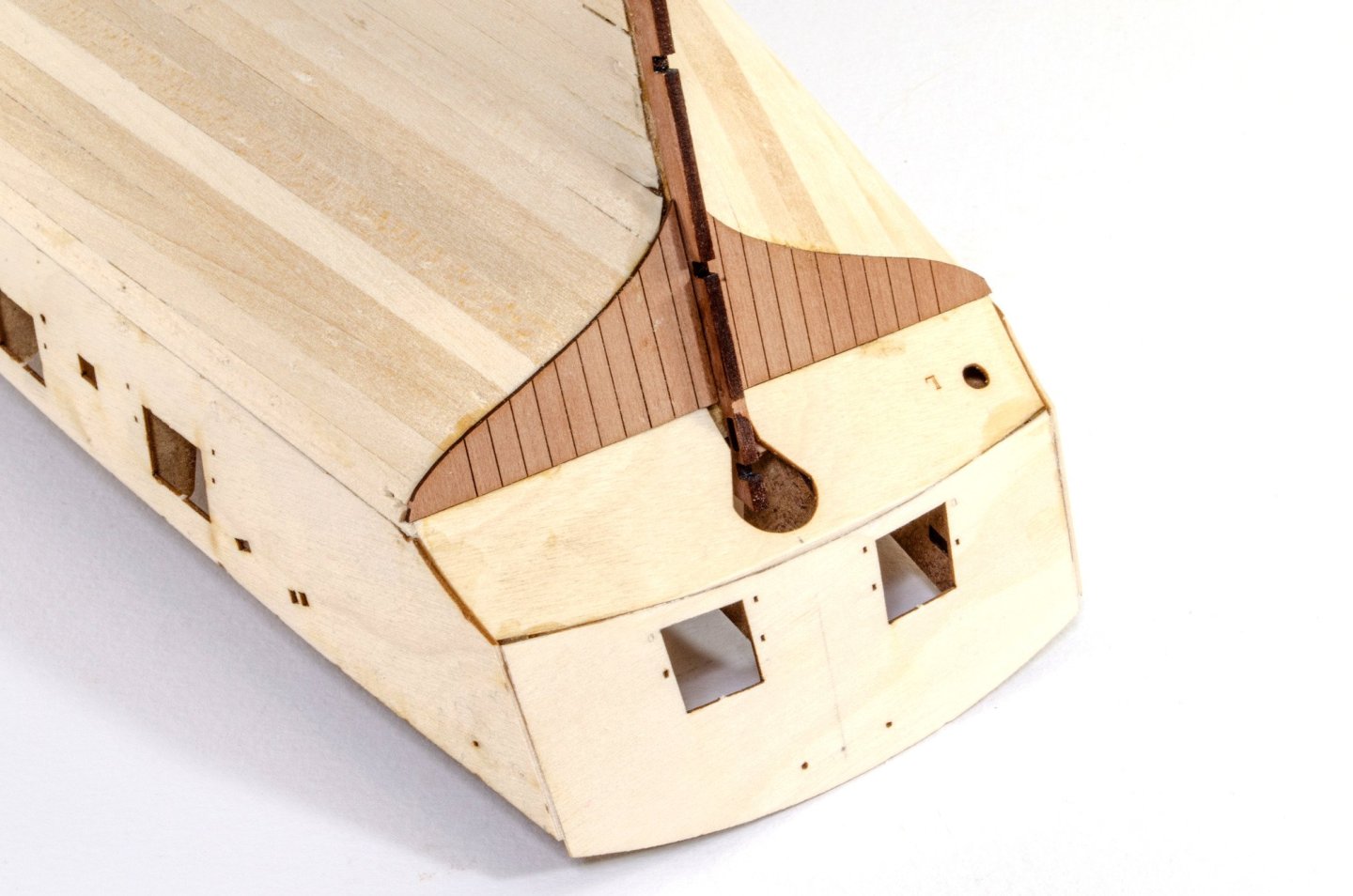
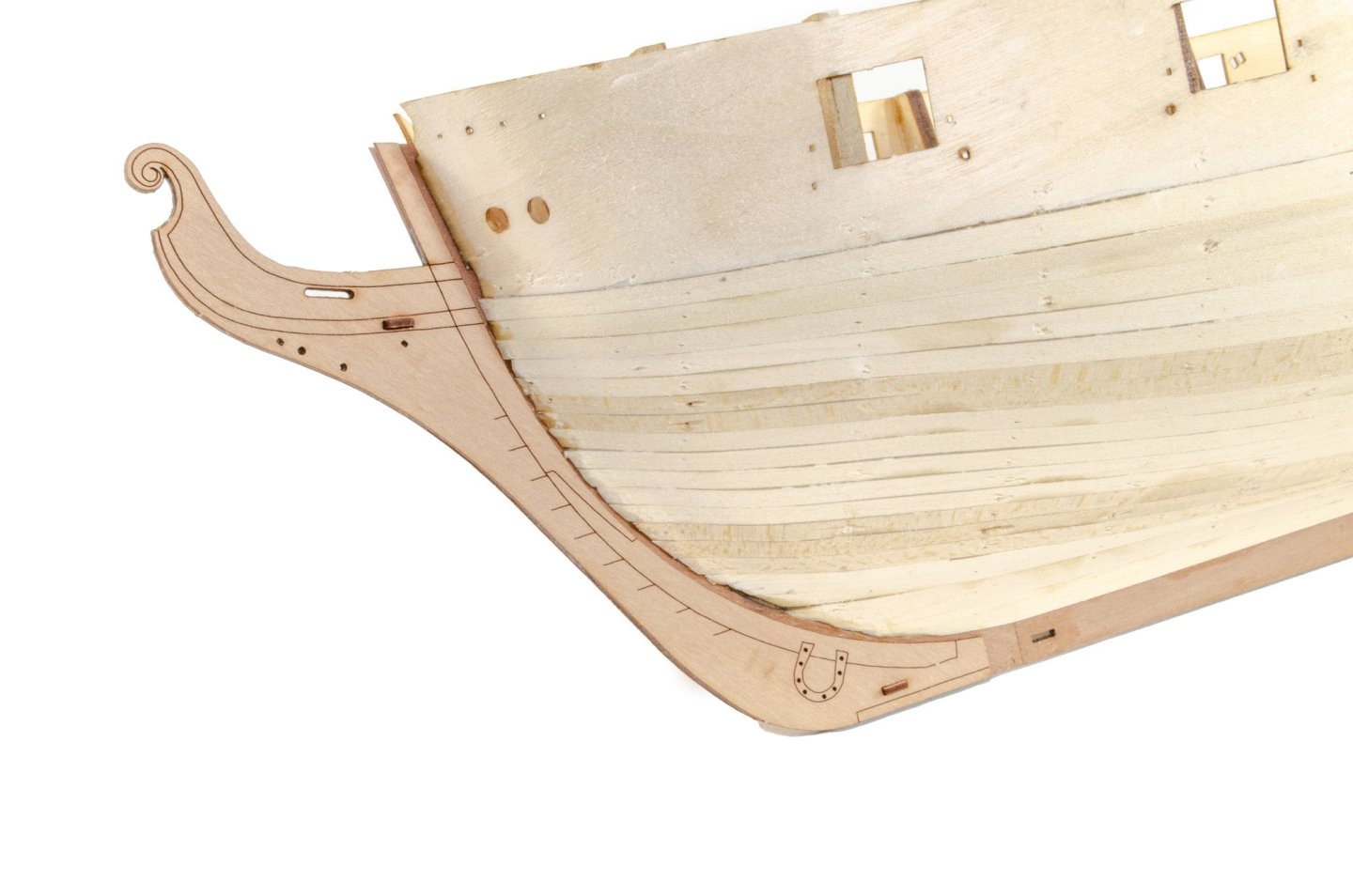
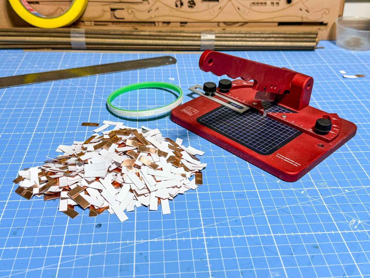
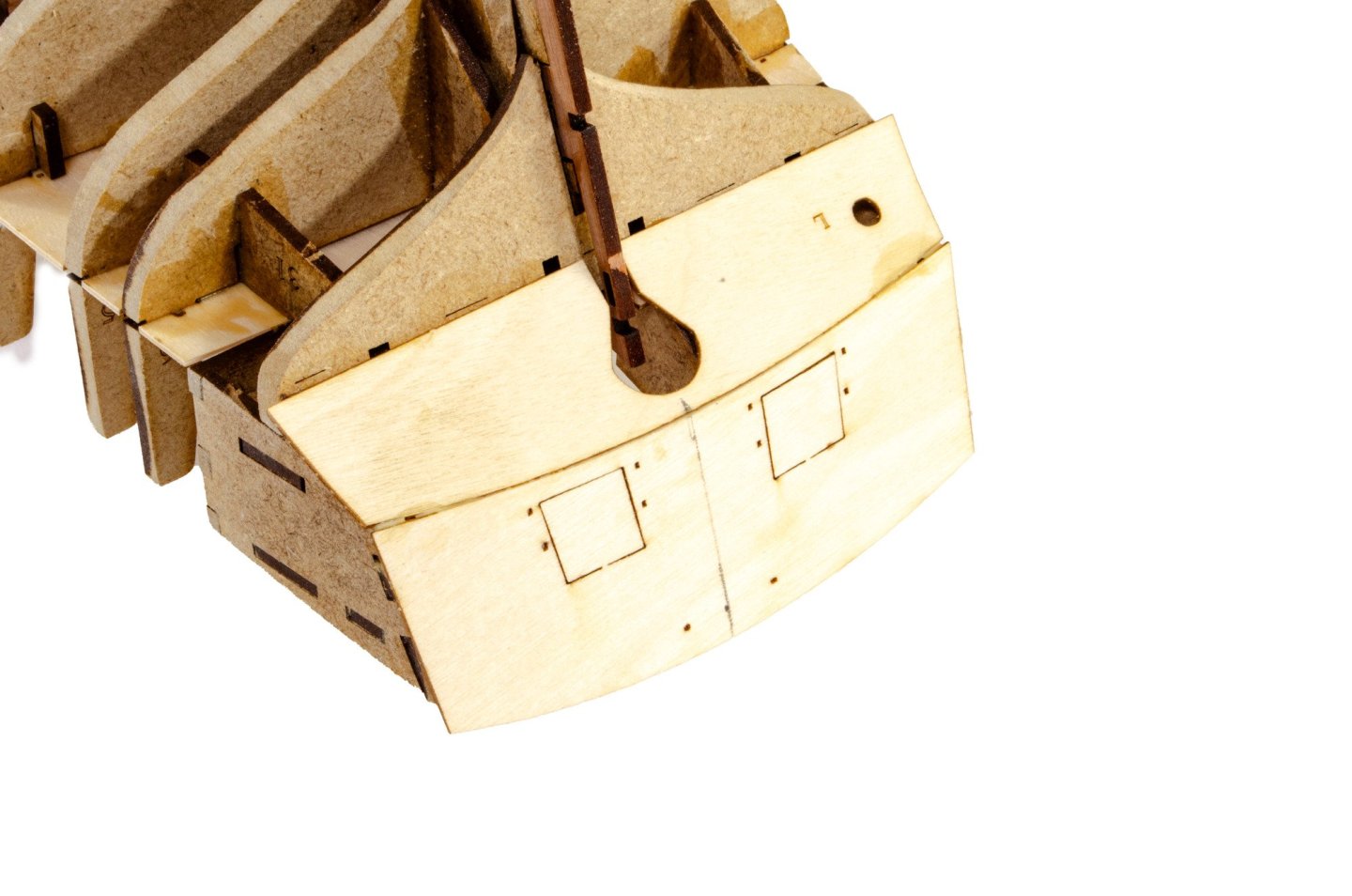
Continued. The hull is now fully planked, and using my usual protective tape on the inner keel areas, the whole lot was sanded smooth. I show a block, but most of the work was done with a sanding mouse, now that I feel confident enough to use it without making gaping holes. The lower stern planking sections are added. These are made up from two engraved parts. Pear prow, keel and rudder post are fitted and wooden alignment pegs used to get the job right. At the moment, I'm waiting for the outer bulwarks to shrink back after soaking. I thought I'd do something useful and got this pile of copper tile made from the roll of self-adhesive copper tape supplied in the kit. Me done for today!


- 76 replies
-
- 34
-
-

-
- Harpy
- Vanguard Models
- (and 1 more)
-
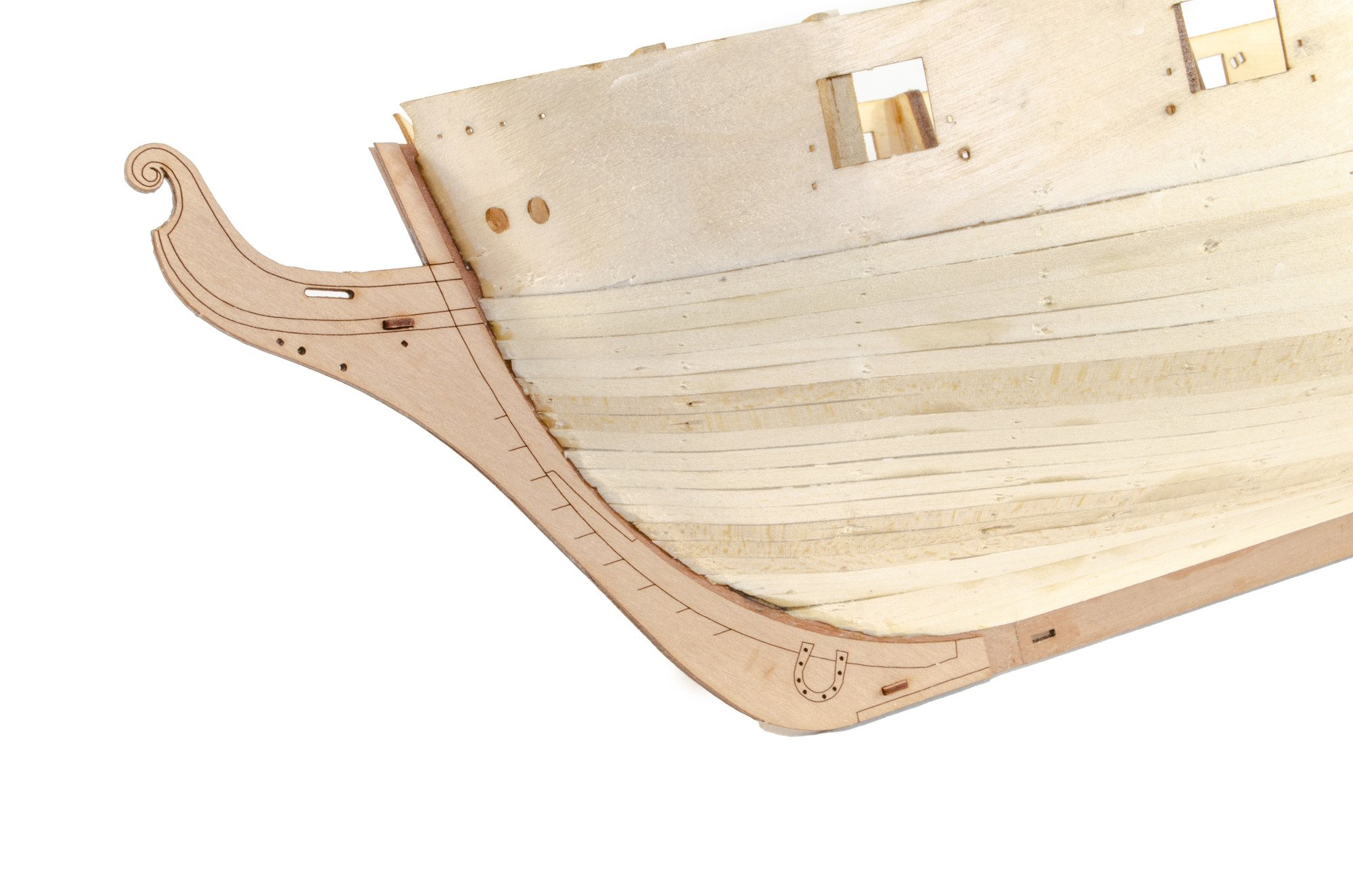
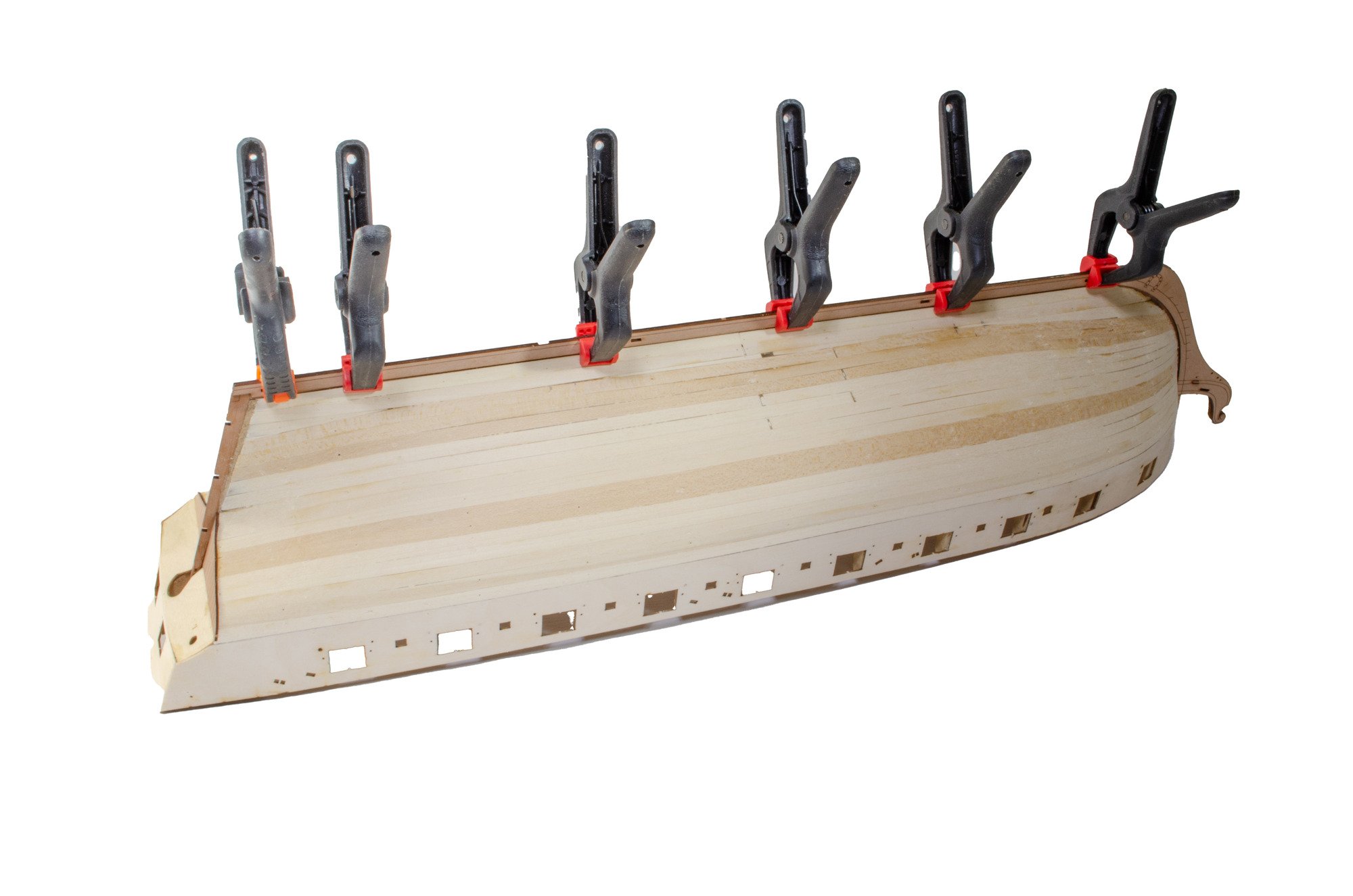
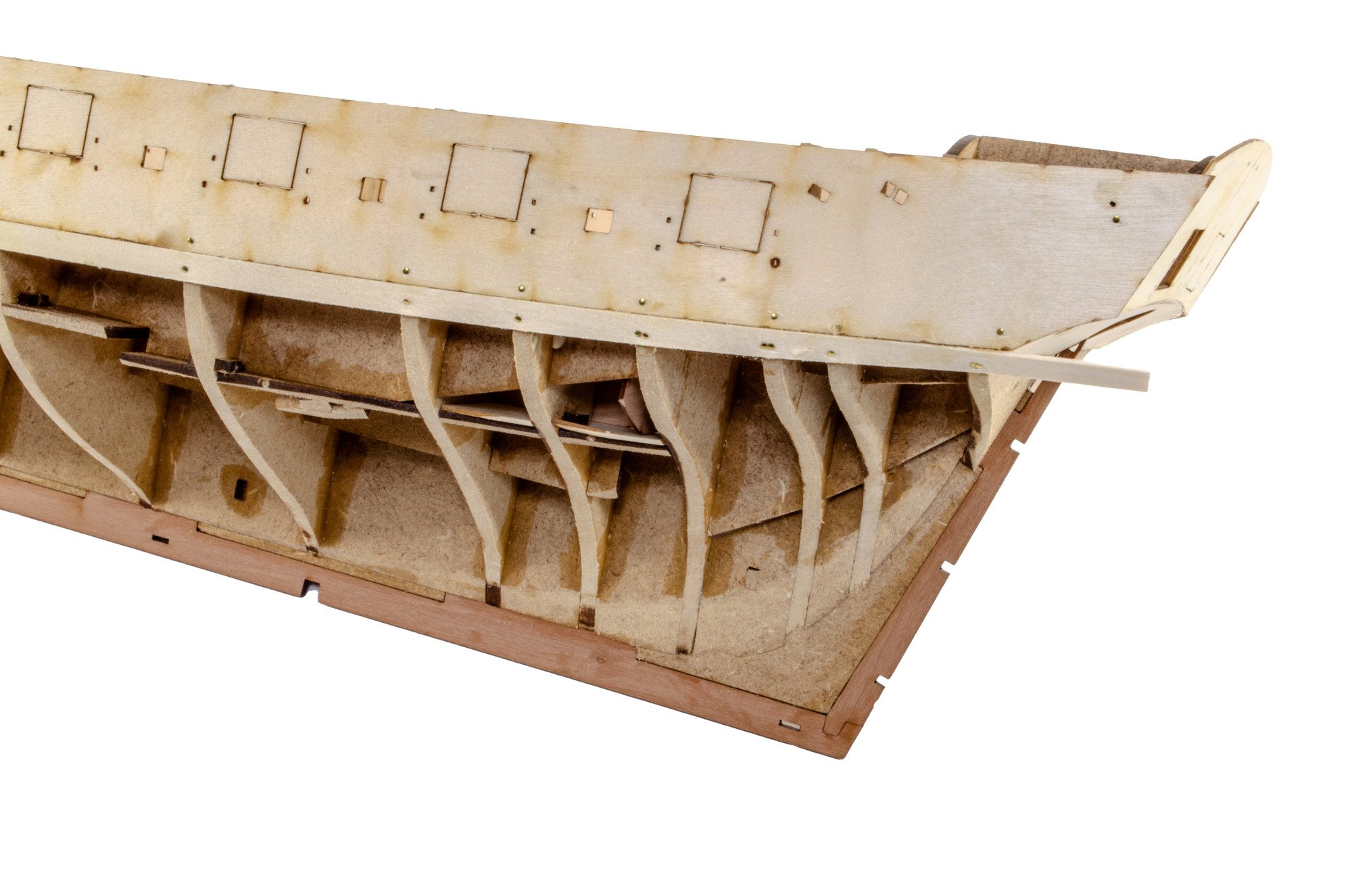
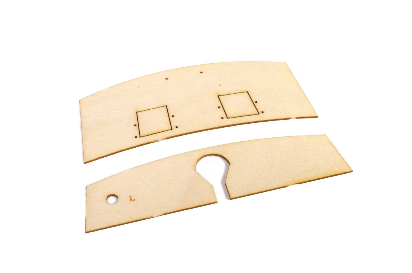
Update time, and possibly my last before I go on holiday. As the weather here had got better, I could finally get the hull faired. With that task done, I went about fitting the inner pear prow, keel and rudder post. I desperately wanted to get onto the stern, to give it more rigidity in that area. These two 0.8mm ply parts were then fitted. I drew some pencil lines to help with fitting these centrally. To curve the lower counter, and save time, I added a series of score lines on the reverse. Any overhang on these parts was now sanded flush with the sides of the hull. To avoid any kinks in the forward area of the ply bulwark (where the gun ports lay), I soaked the parts and then used an iron and curved block to shape them. These were then fitted/pinned dry. When happy with the positions, they had glue brushed into the joint areas. Planking is done in my usual cack-handed way. With this hull, the lines are very easy to plank and hardly any stealers needed to used. A first for me±


- 76 replies
-
- 23
-
-
-
- Harpy
- Vanguard Models
- (and 1 more)
-
Absolutely blown away! Will the furniture, lamps etc. be included with the kit?
-
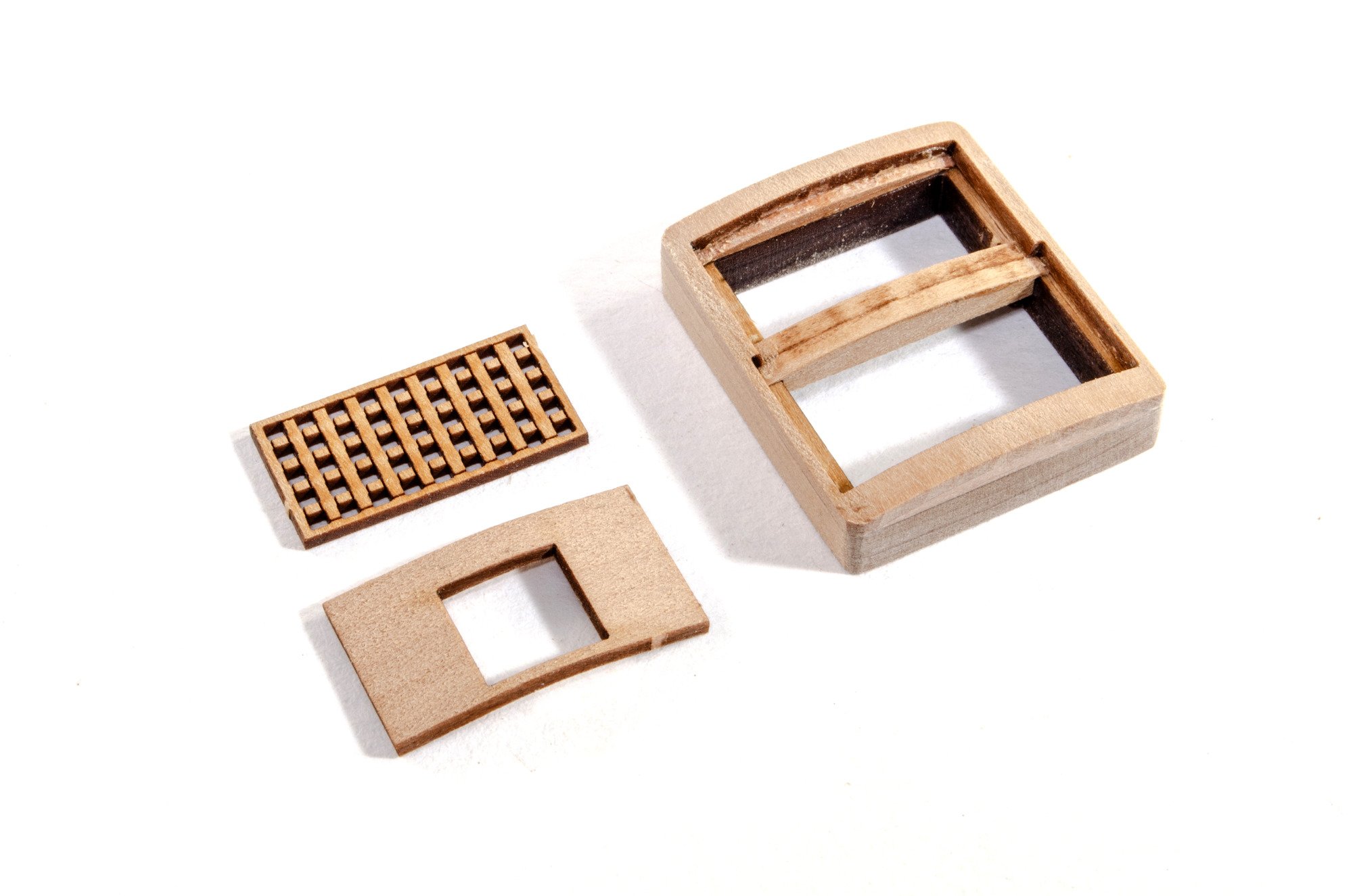
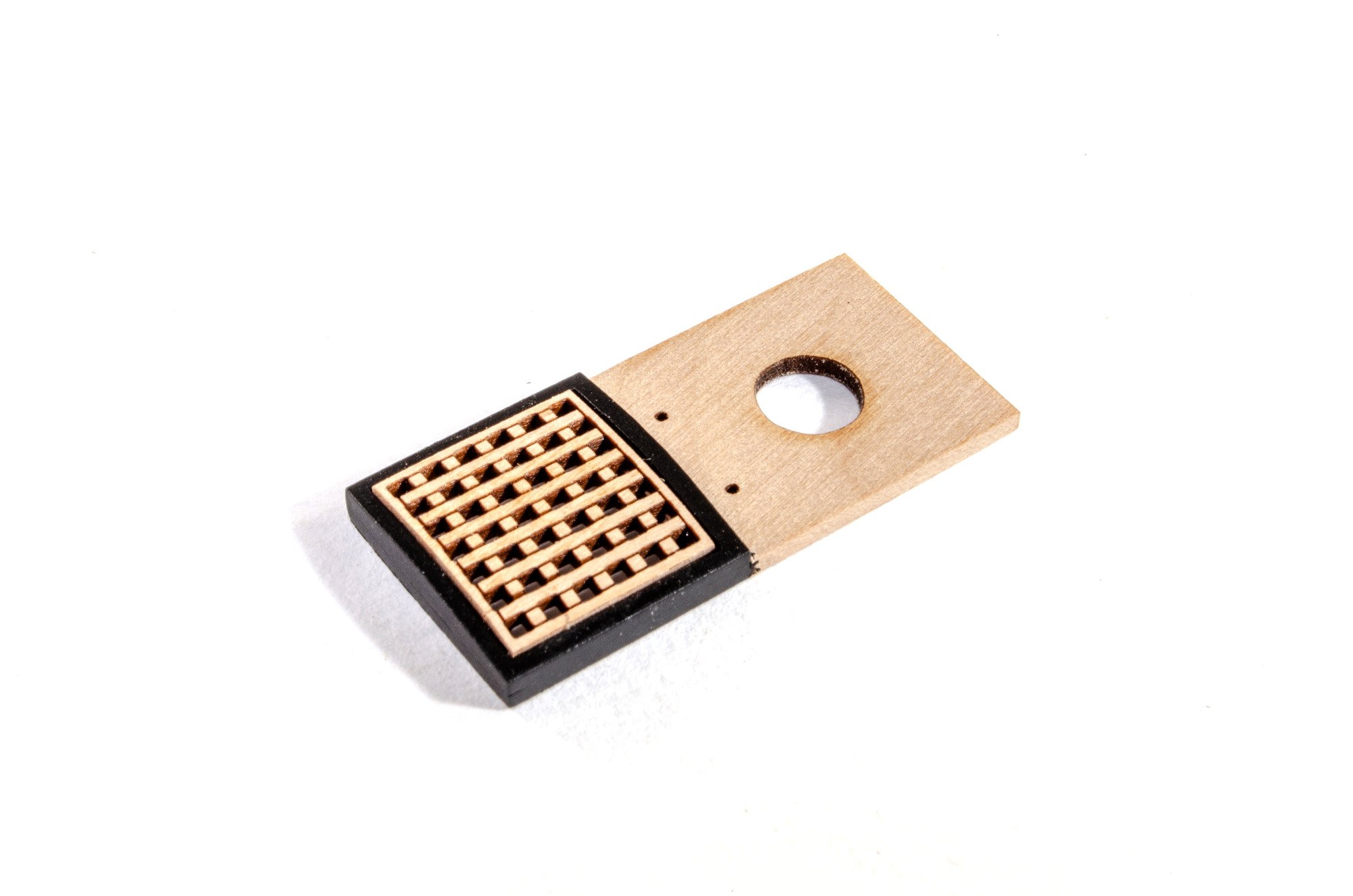
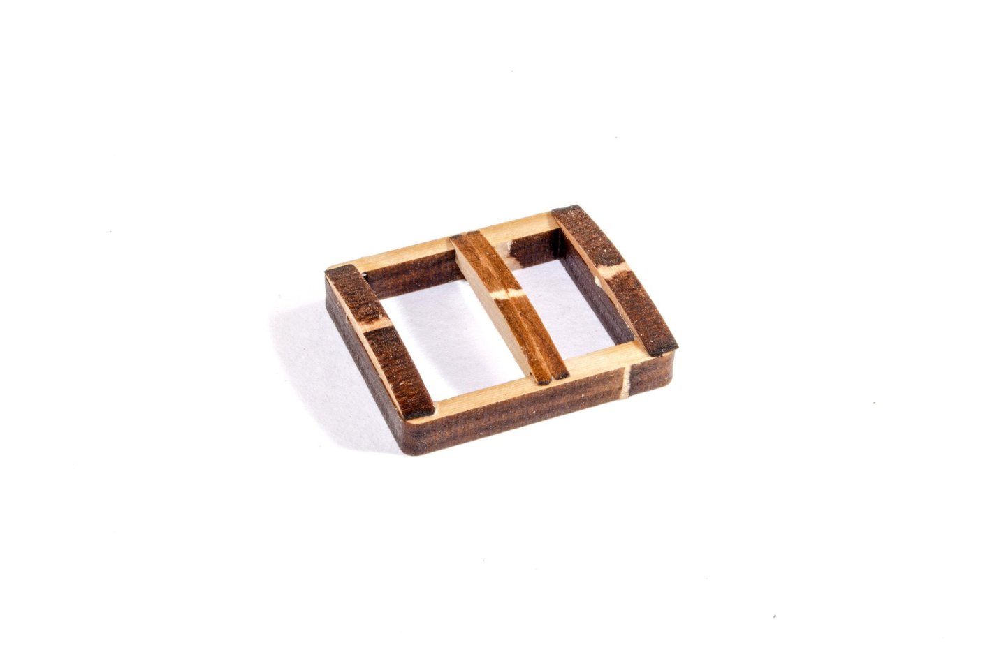
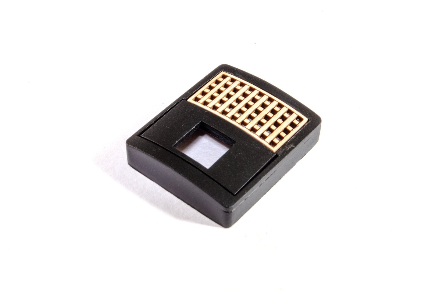
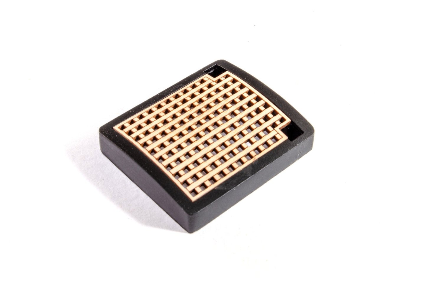
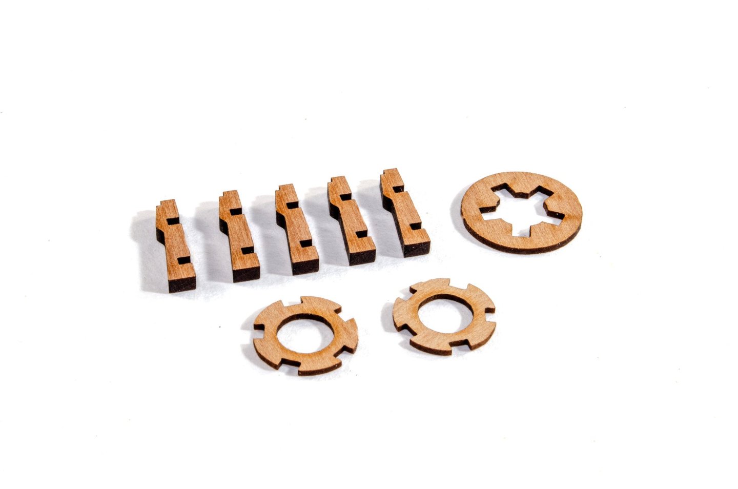
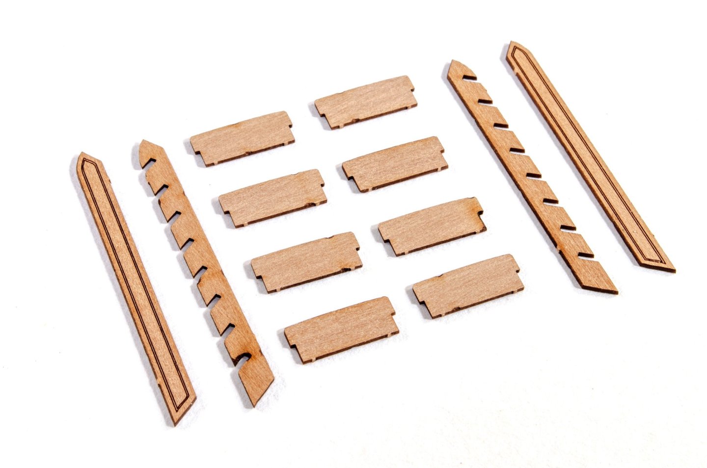
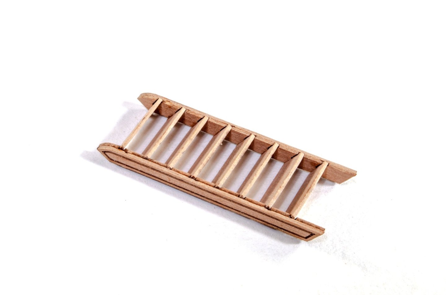
Last one for today. Bitts These need no explanation. They'll also be painted red before fitting to the hull. Grates I'm only showing one unit being built here as they all follow the same pattern, including the coaming that accepts the ladder to access the lower deck. These coamings have curved tops, and are identical in shape to those on the shipyard plans. First, we have to glue the curved top parts into place on the body. I now soak all the tops and wrap around a tin until thoroughly dry. The centres are also temporarily left in place to add strength and make it easier to neatly and evenly sand the tops of the assemblies. After sanding the units so they are smooth, the coamings can be painted black. Note that this unit has another curved part. This is where the stove chimney will protrude. Until next time...


- 76 replies
-
- 29
-
-
-
- Harpy
- Vanguard Models
- (and 1 more)
-
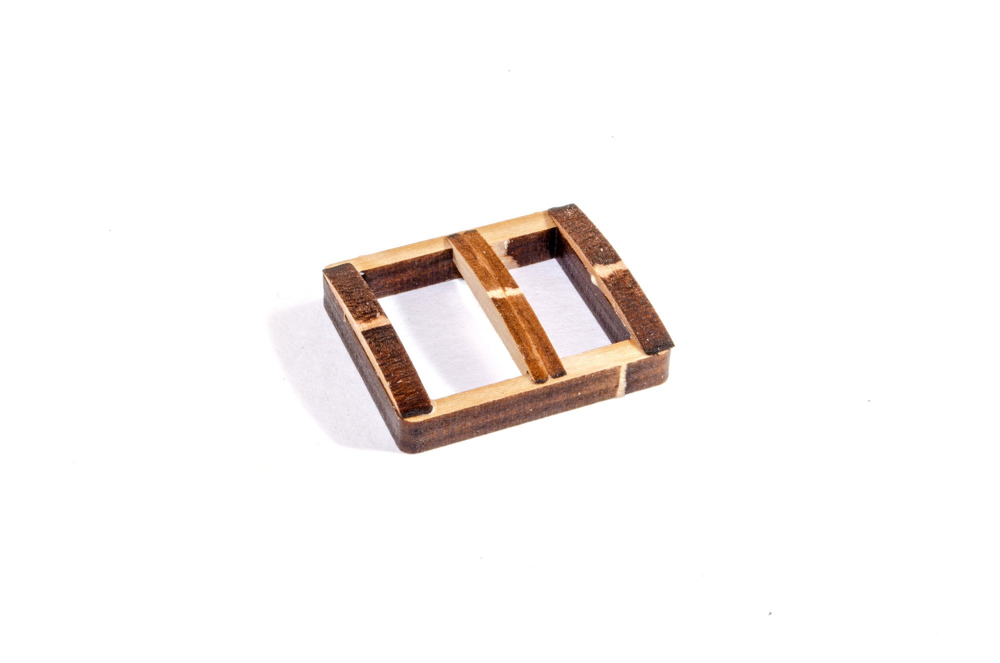
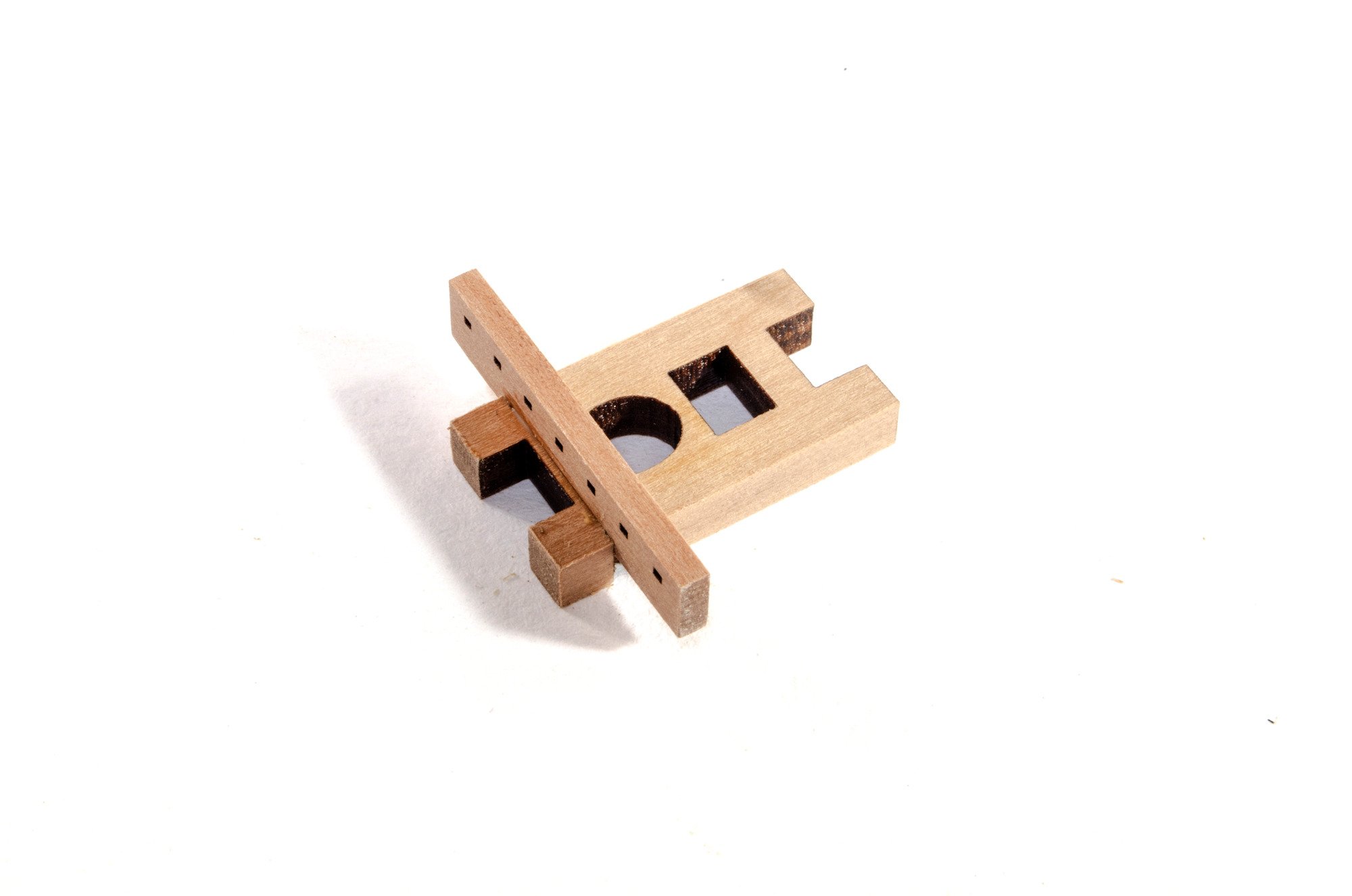
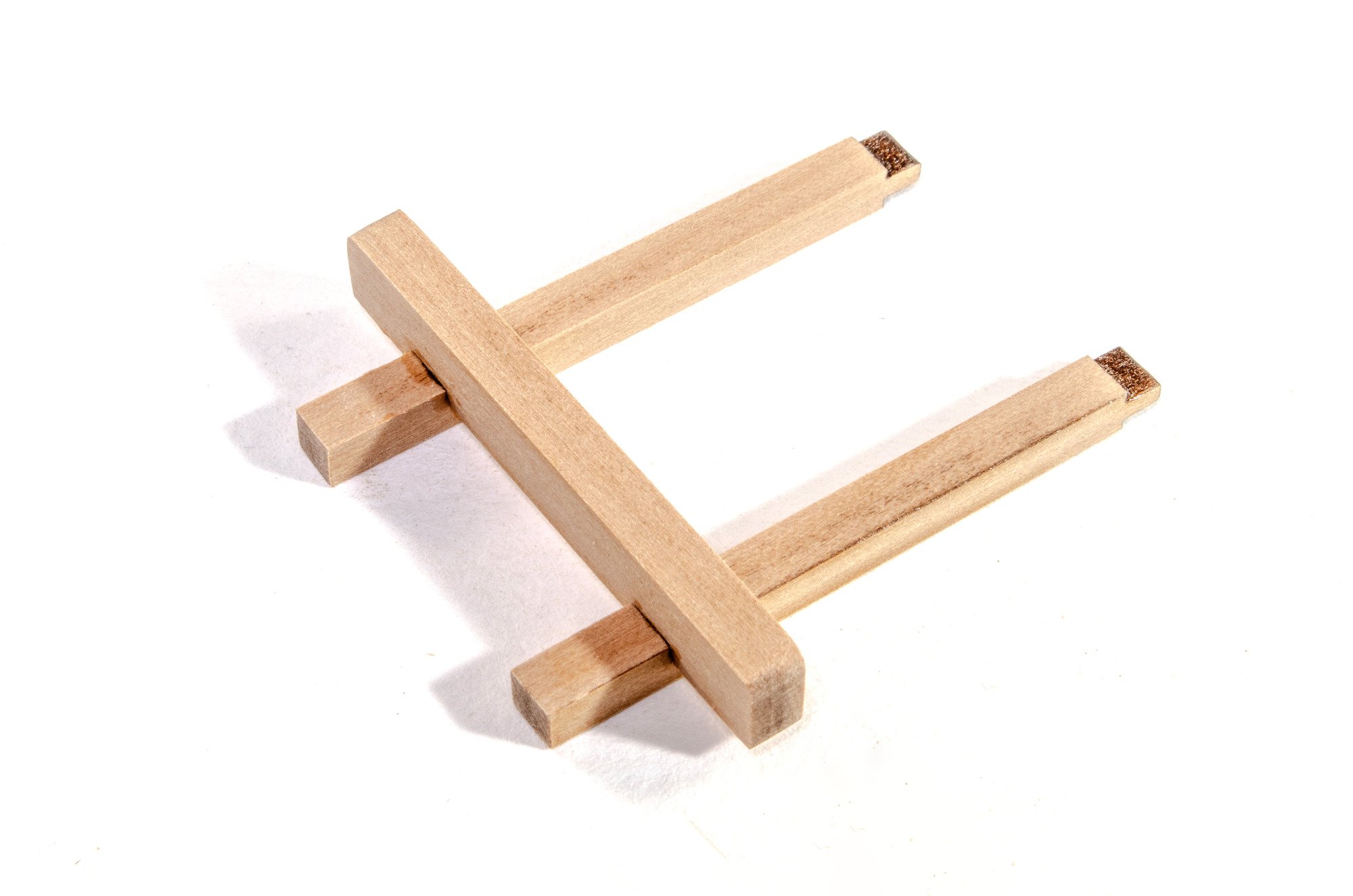
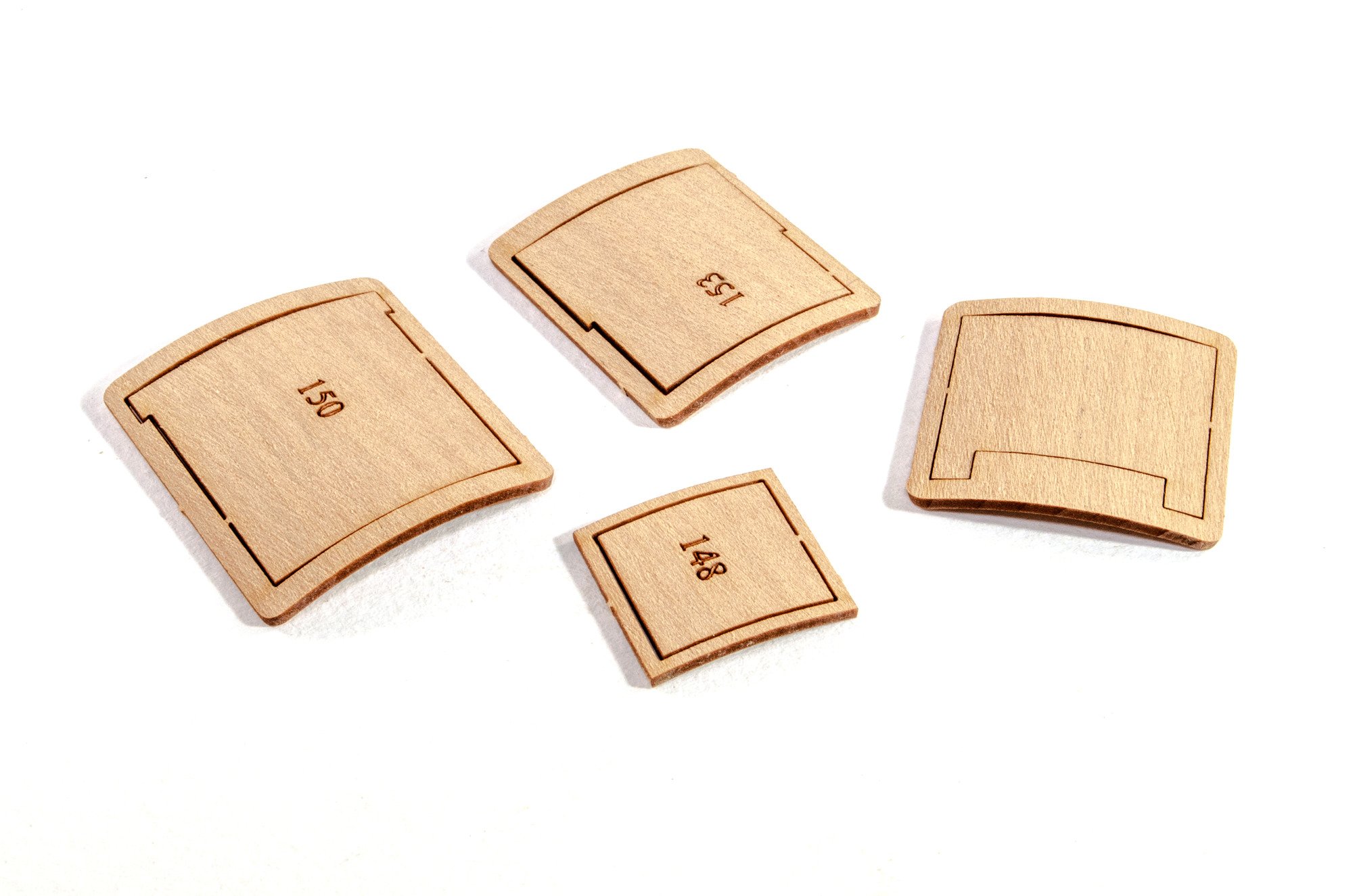
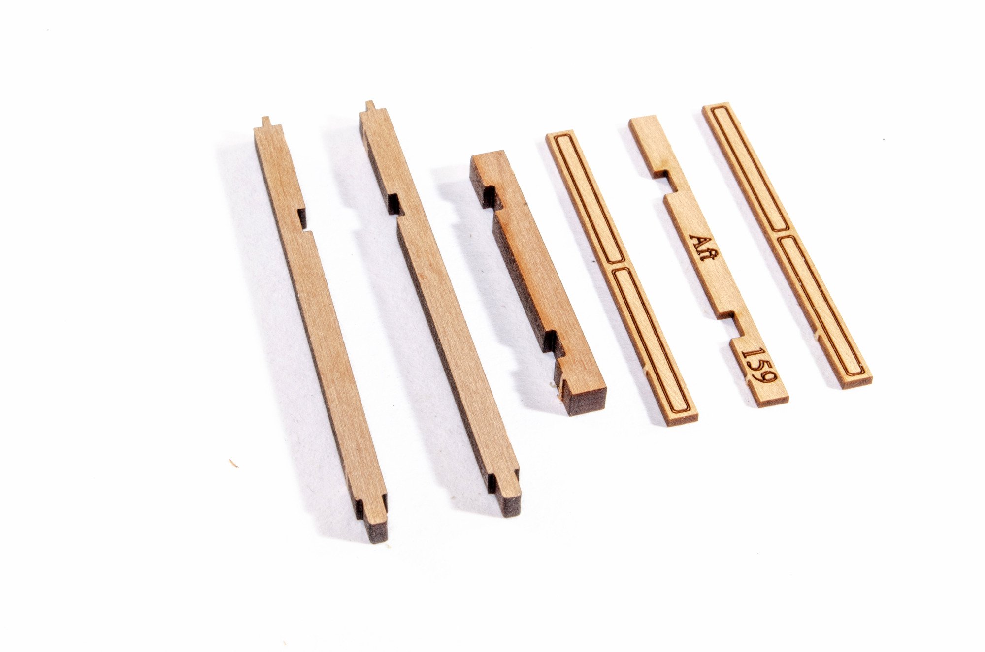
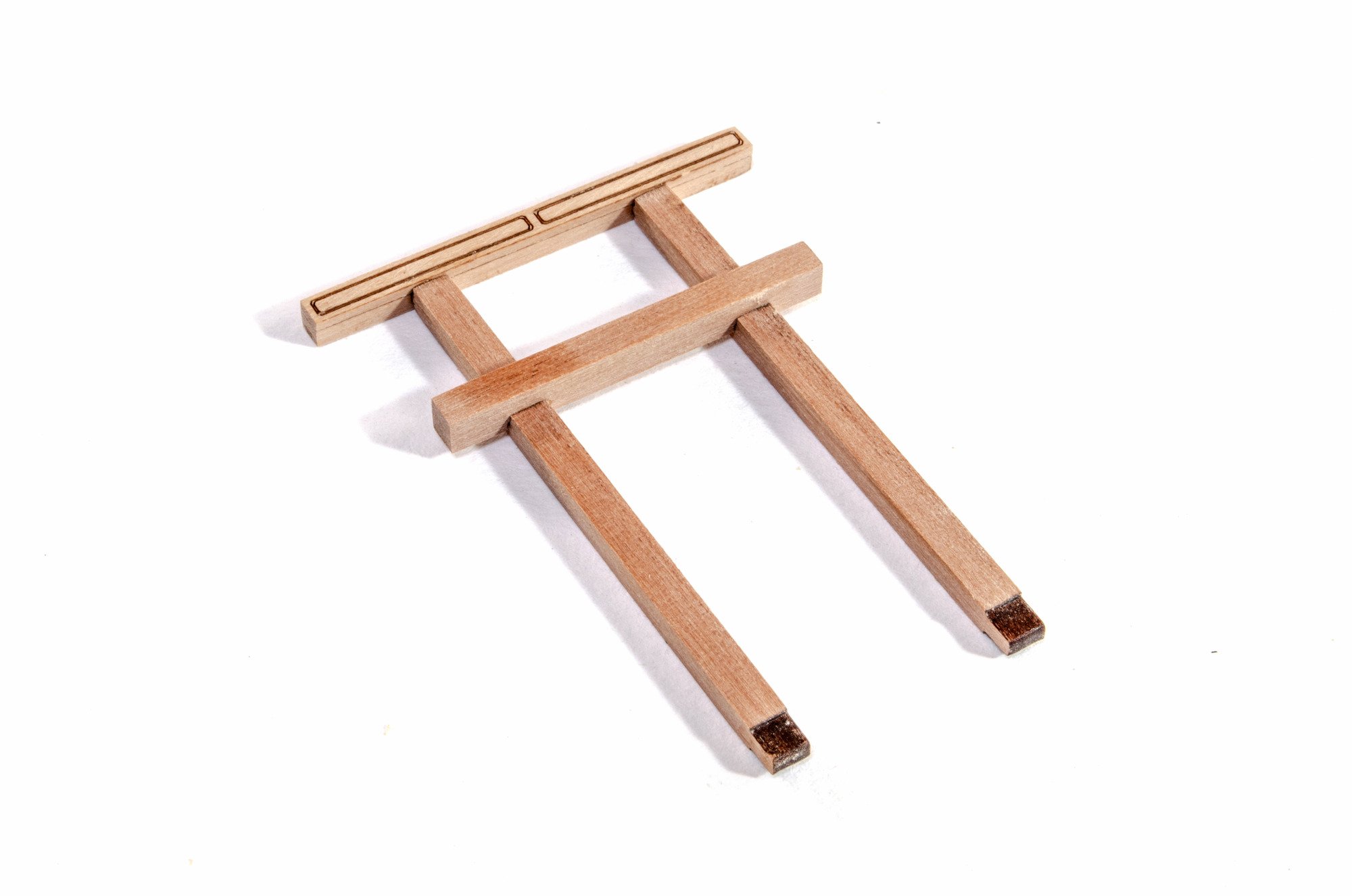
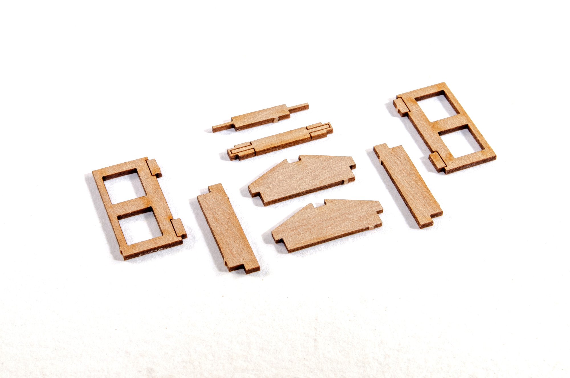
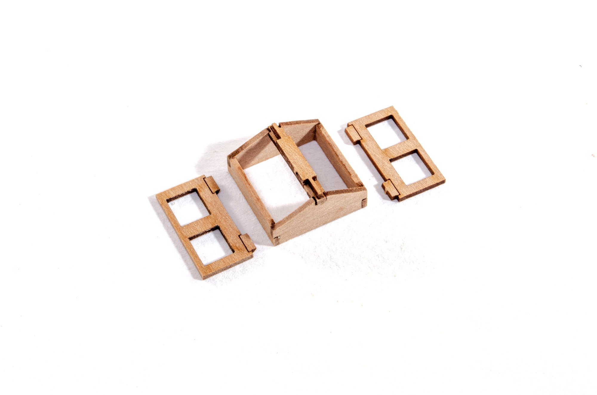
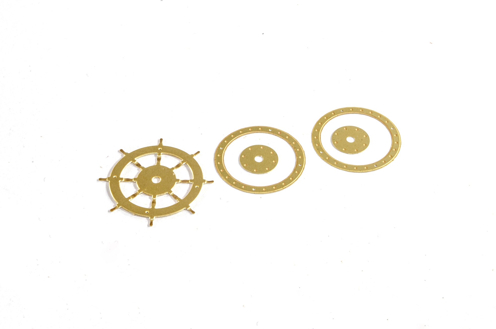
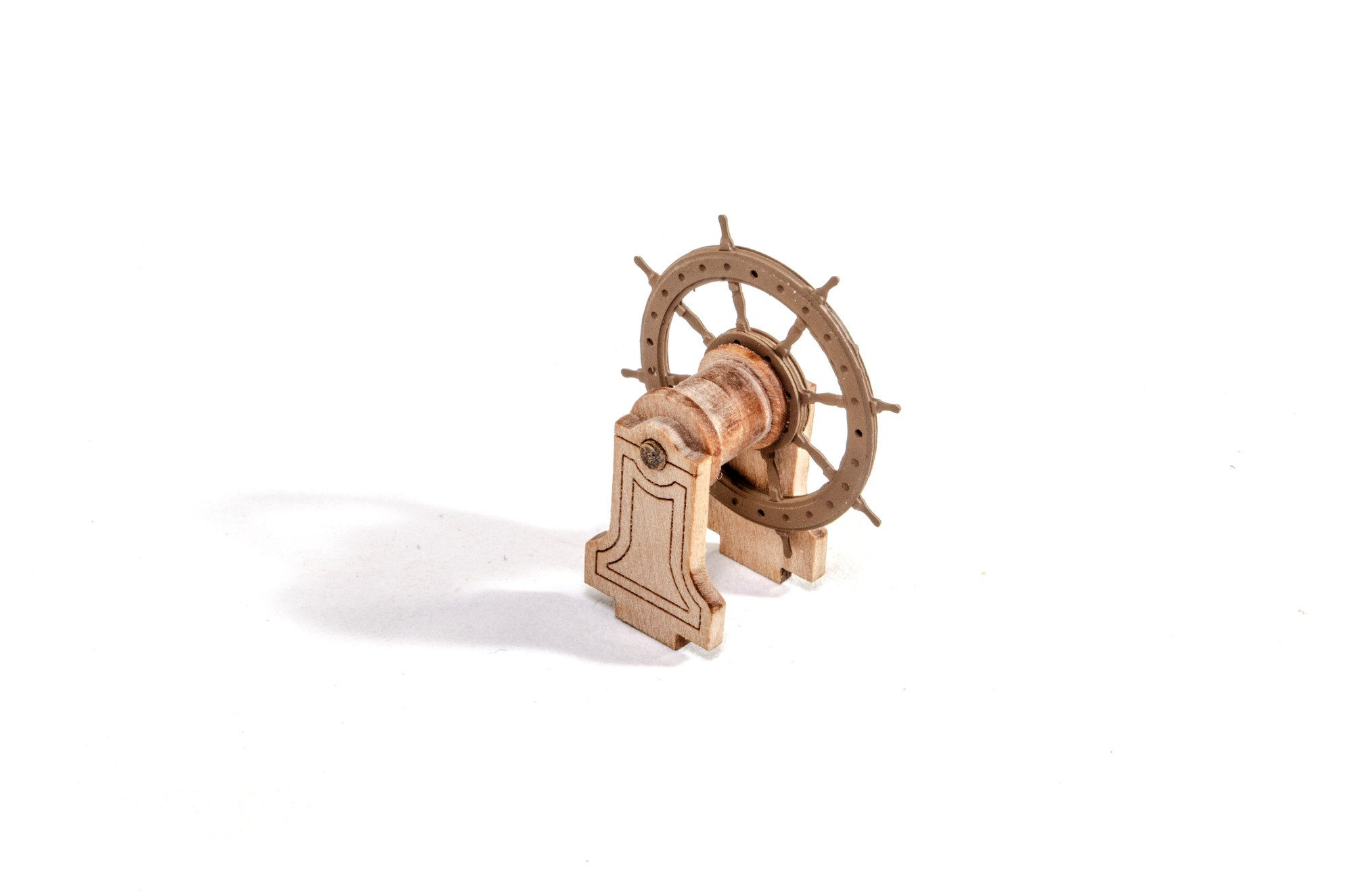
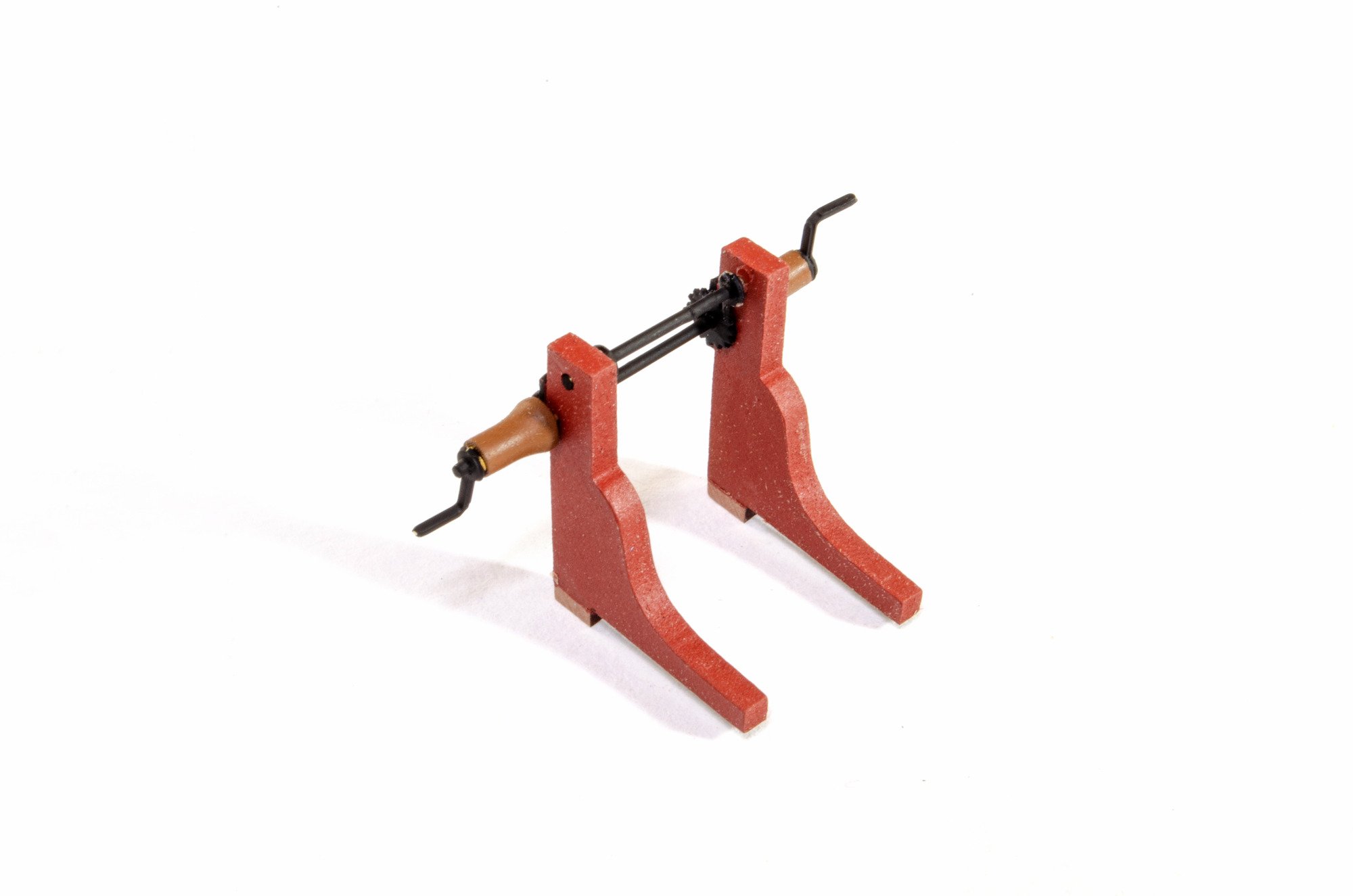
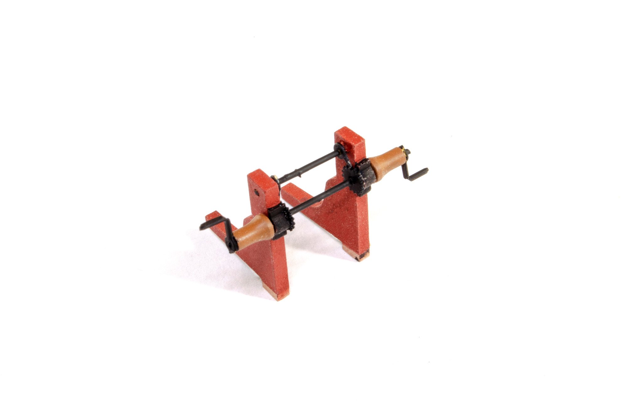
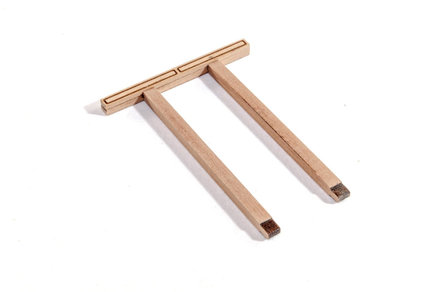
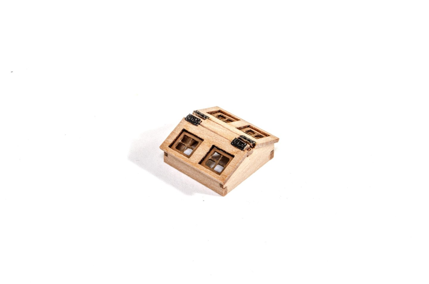
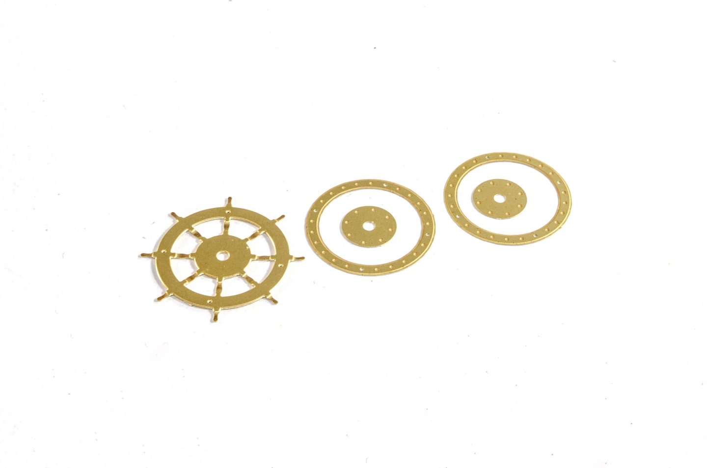
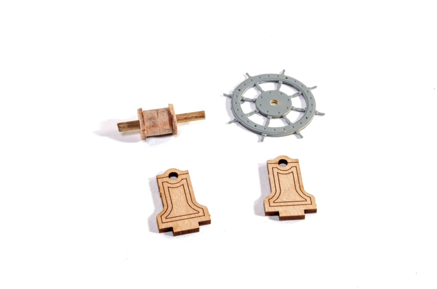
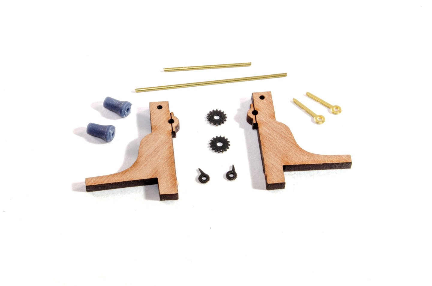
Gallows There are two of these, slightly different. The head bar is composed of three parts which build up to make a unit which is recessed centrally to accept the vertical posts. Skylight This is very similar to skylights on some other VM kits. The photos are self-explanatory. Wheel And again, the construction of the wheel unit is identical to some other VM kits. This is centred on a drum unit which is sandwiched between the main posts, along with a photo etch wheel which is built from six parts before priming and painting in a brown colour. Winch As with the bitts and gallows, this is painted red before assembly, and the 3D printed drums are painted brown. The side parts need to sit in the deck slots so the unit is properly spaced when assembled. More in a very short while.


- 76 replies
-
- 18
-
-
-
- Harpy
- Vanguard Models
- (and 1 more)
-
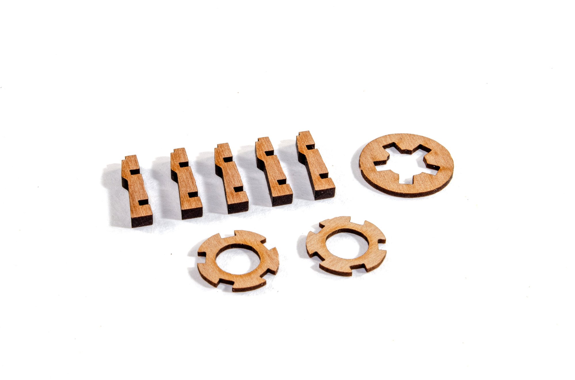
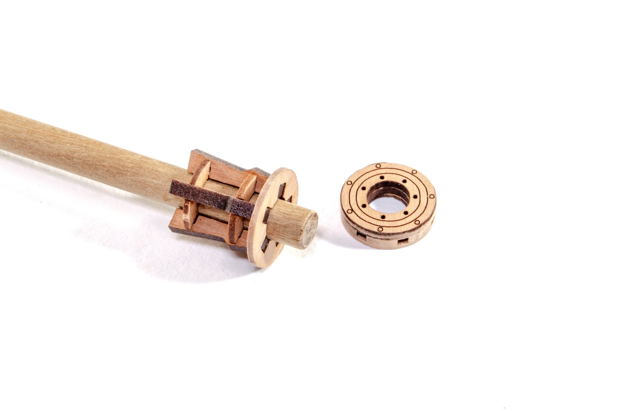
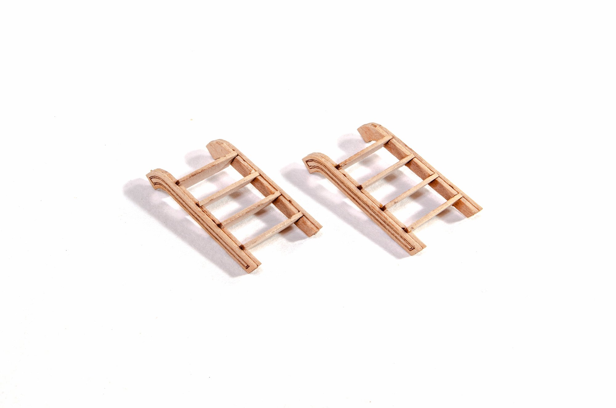
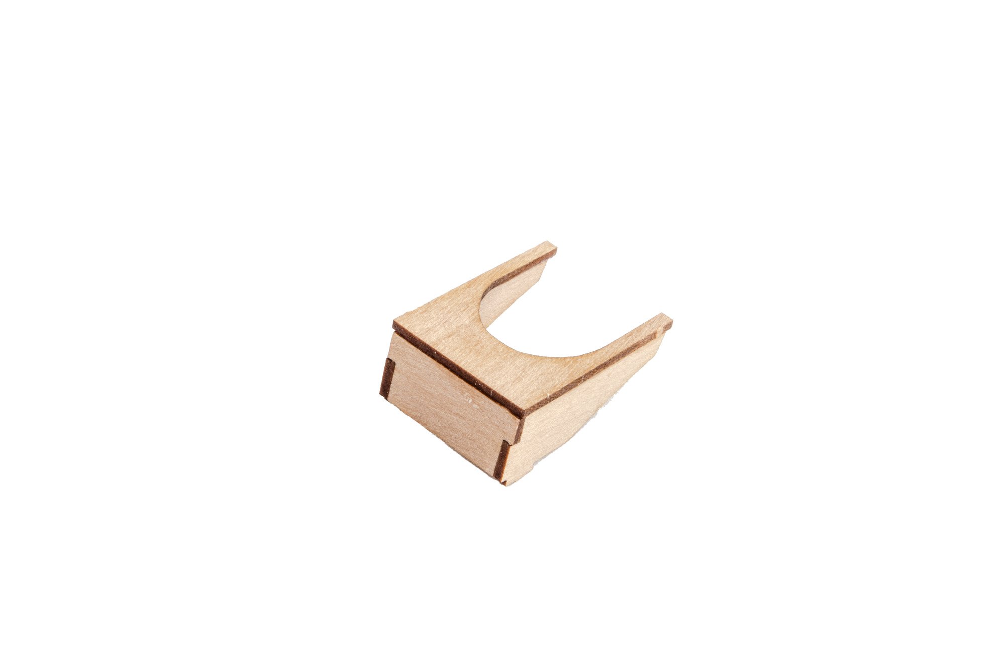
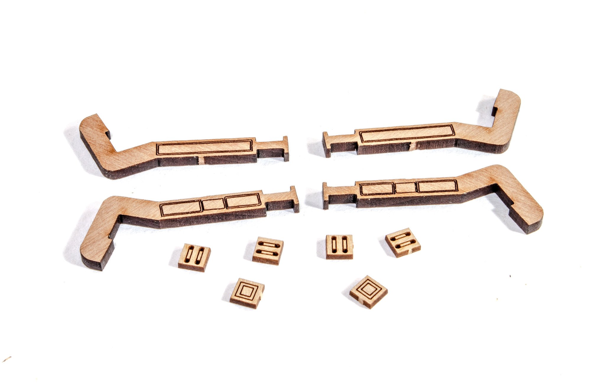
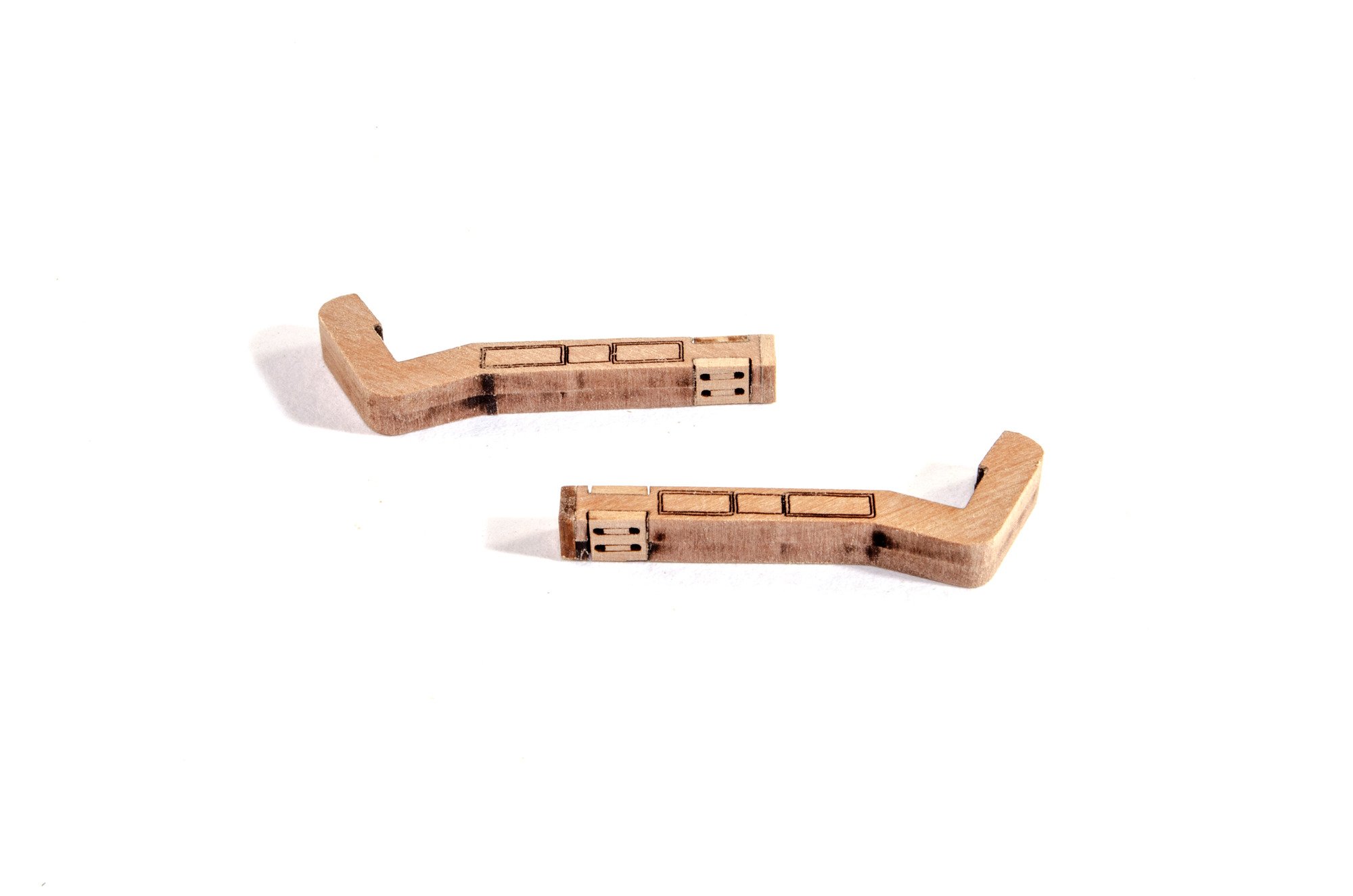
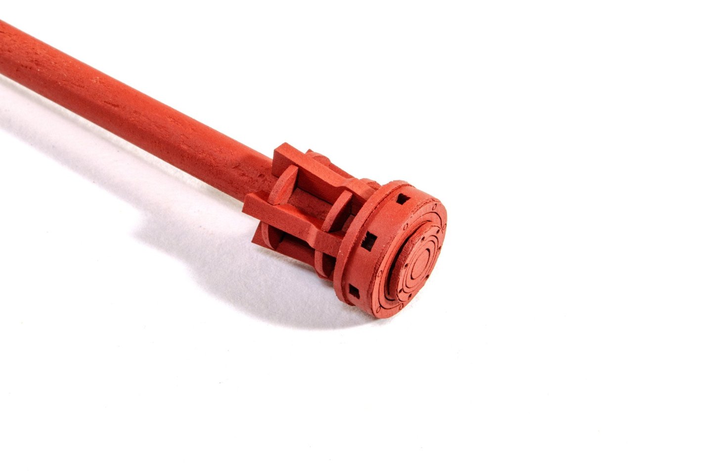
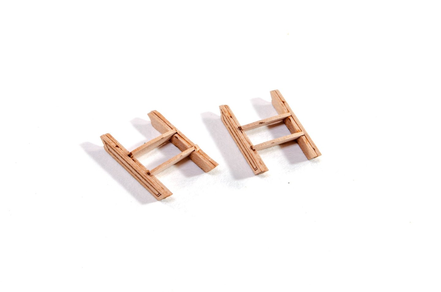
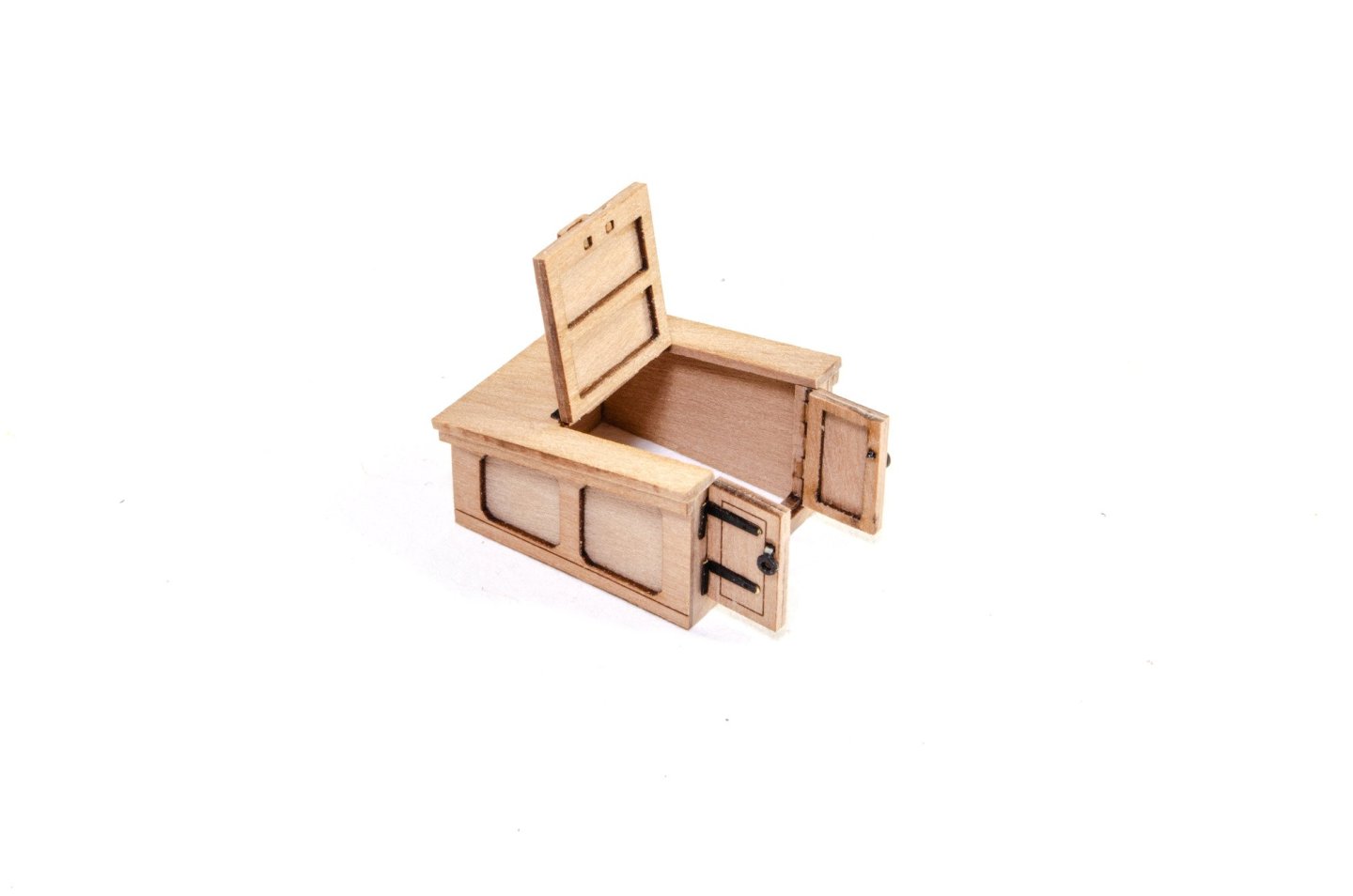
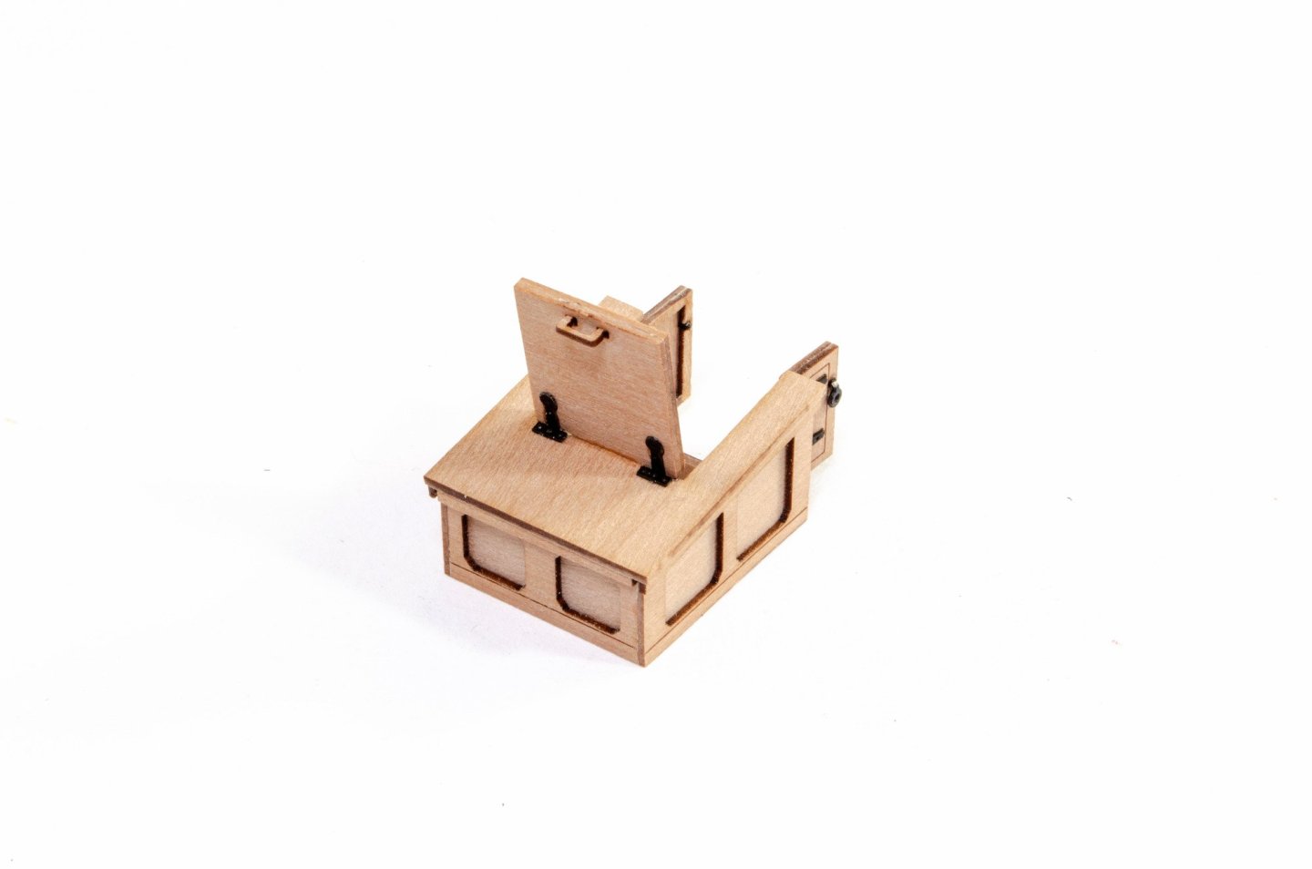
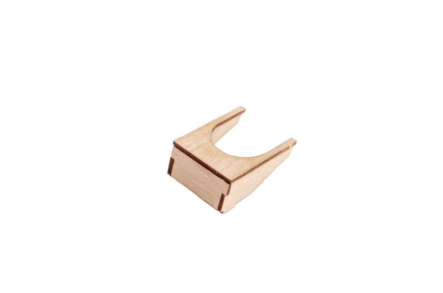
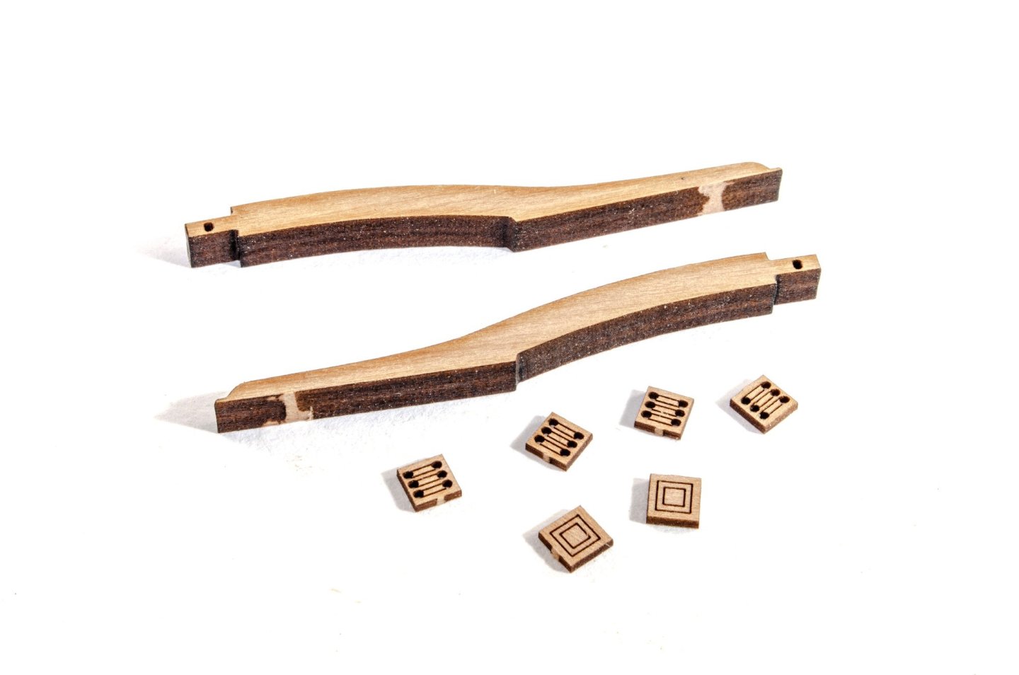
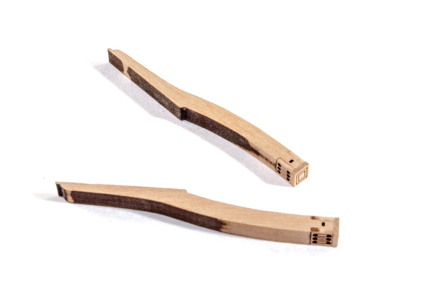
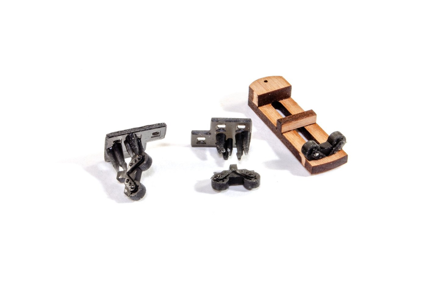
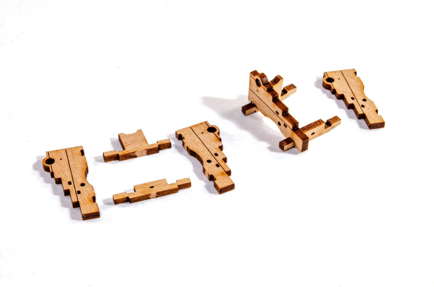
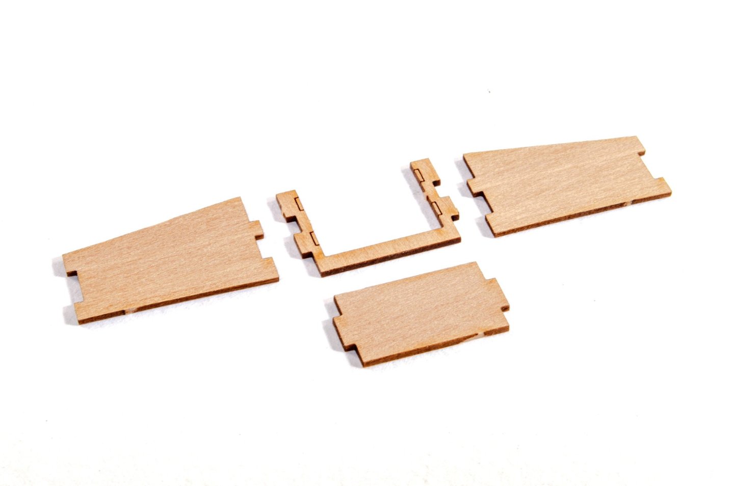
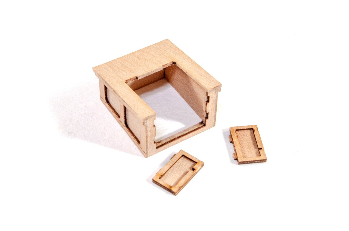
At this point, the hull still isn't faired, but that should happen tomorrow. No time lost though as all of the various fittings and fixtures are now complete, and these next few posts will show you a little of what I have done. There is a degree of work that I'm also not showing here as it's irrelevant at the moment.....such as gallows, bitts etc. painted in red. Ok, here we go. Capstan If you've build any VM kits, then this capstan's construction will be very familiar, so here are just a few images showing it up until the painting sequence. Ladders It's the same with the ladders. These are a tried and tested formula. Harpy has six ladders of various sizes and shapes, including the ones fitted for boarding. Final photos for companionway As you can seem these now have the PE parts fitted. The companionway will simply be varnished, as will the skylight and wheel unit, so extra effort has been made to make this look pretty. Rudder box The original plans show something that looked like boxing around the rudder protrusion above deck. This was determined to be something that would likely have looked like this. At this stage, this just needed a nice sanding to even it up and clear up the charred ends. Davits These hang over the stern and provide an option for hanging the ship's boat. These are simple to build and involve adding the winch holes and end caps to the main parts. I've only cleaned these up enough to blend those parts to the main body, as the whole lot will eventually be painted black. Catheads These consist of two engraved parts which are glued together and then fitted with the winch holes and end caps. These will also be painted black before being fitted to the hull. More in a moment...


- 76 replies
-
- 16
-
-
-
- Harpy
- Vanguard Models
- (and 1 more)
-
I'm doing the grate coamings in black. Stern 'cabins' in natural, companionway in natural and the skylight painted. Not sure whether red or black yet....or even the colour of the wheel stuff yet. Open to suggestions!
- 76 replies
-
- 6
-
-
- Harpy
- Vanguard Models
- (and 1 more)
-
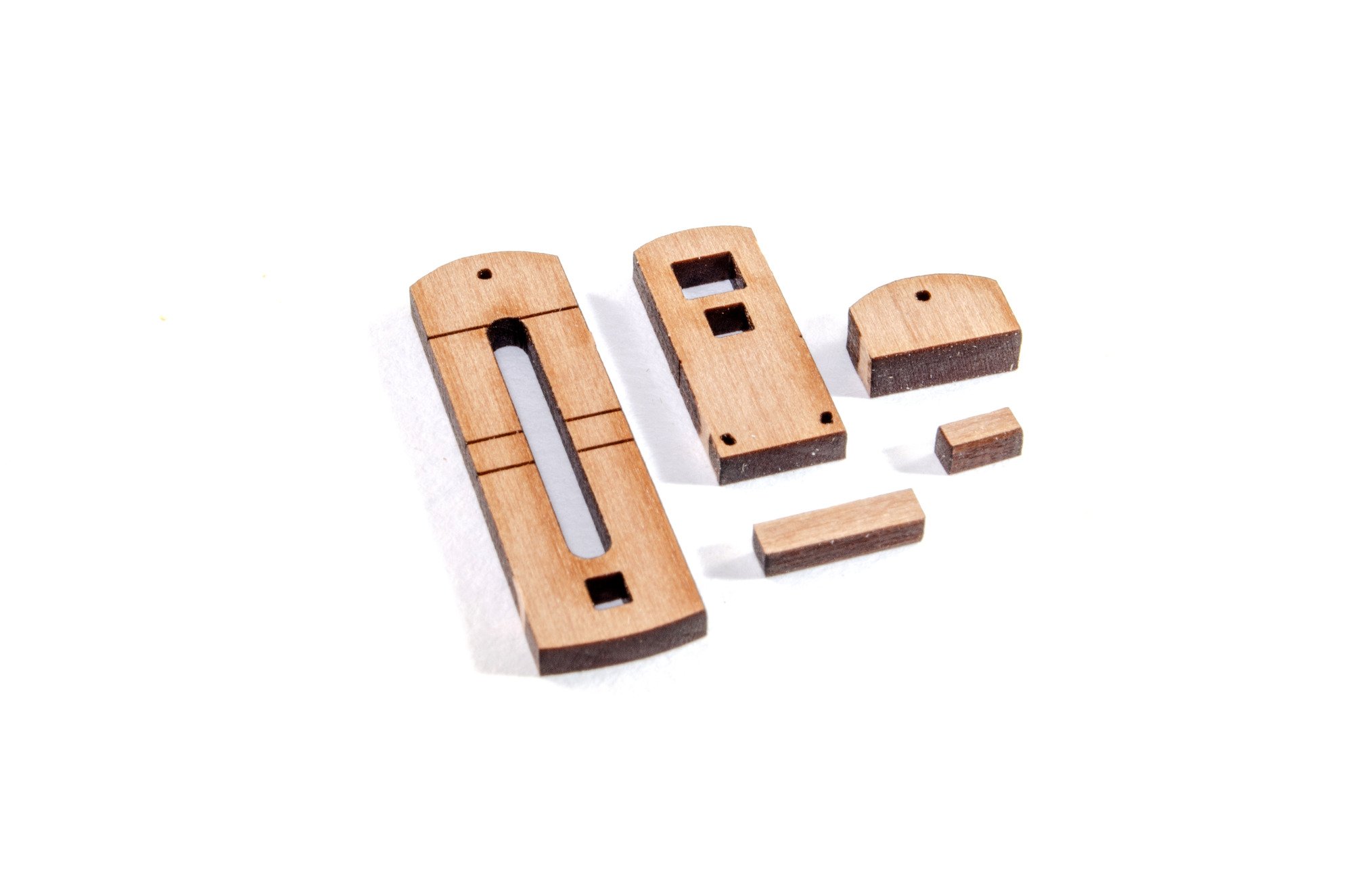
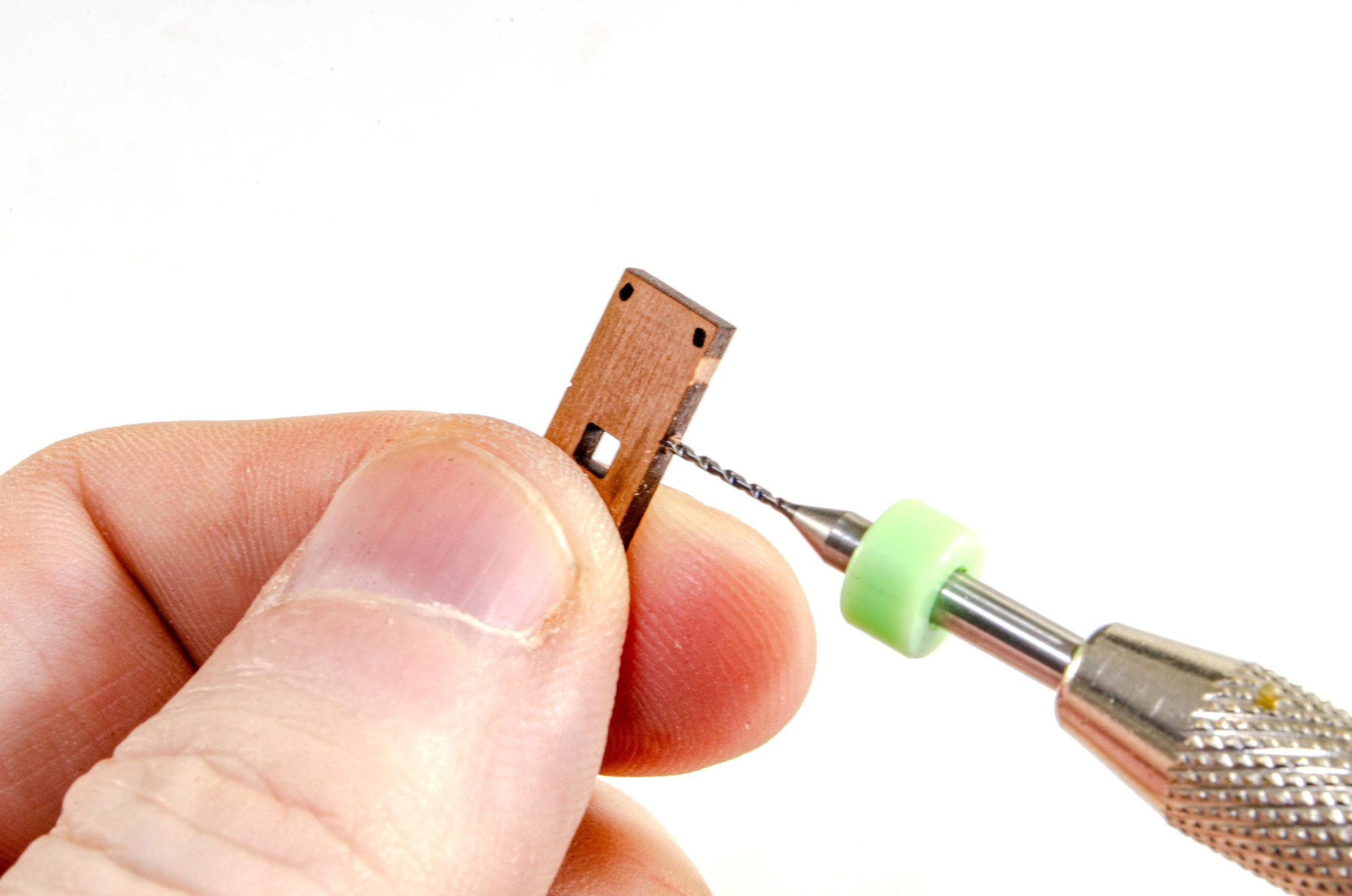
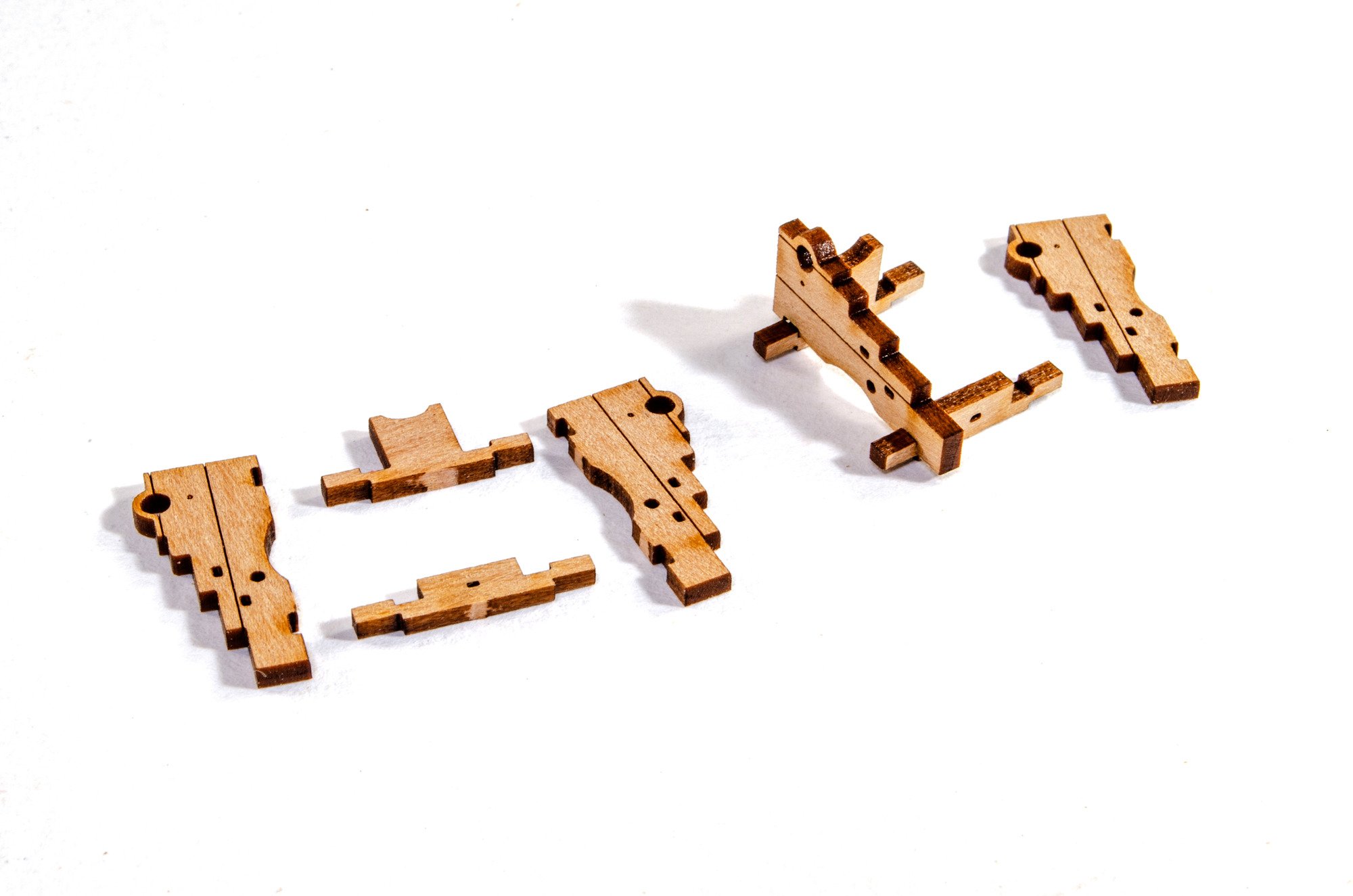
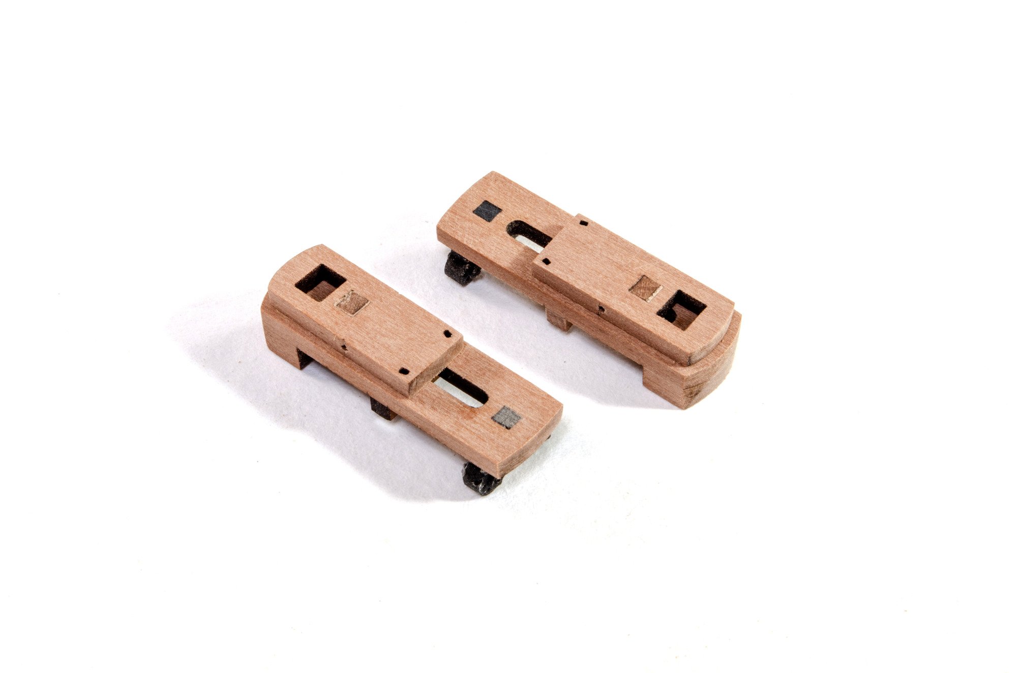
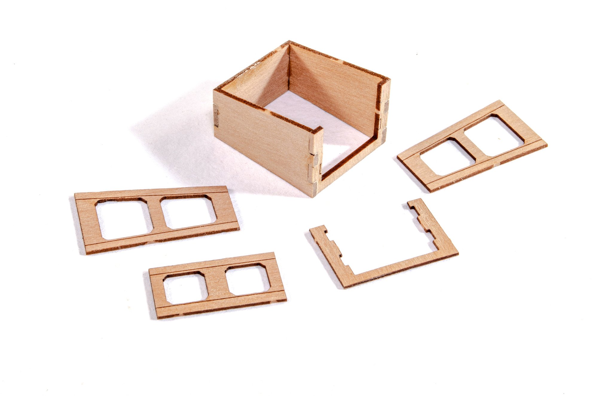
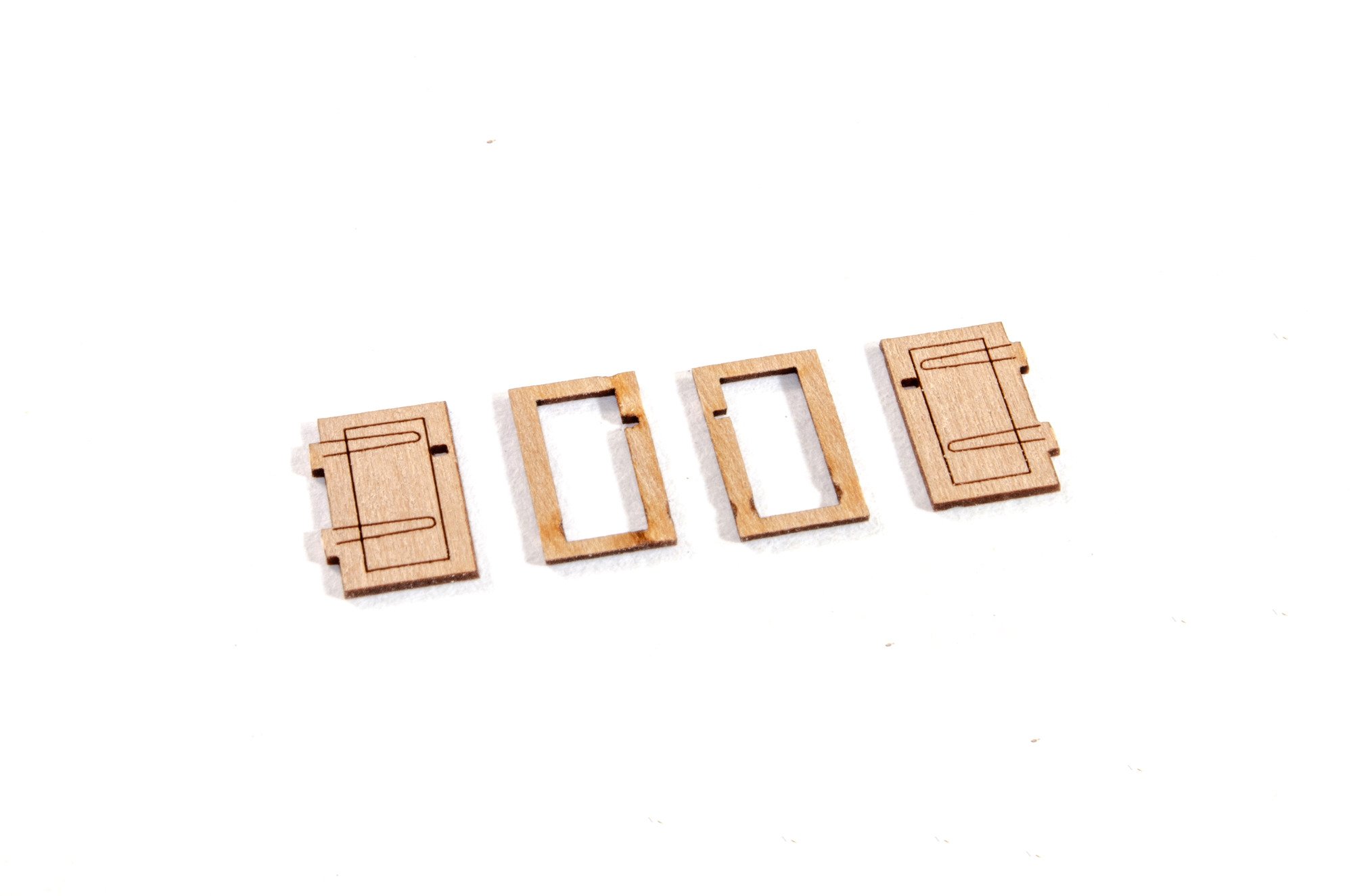
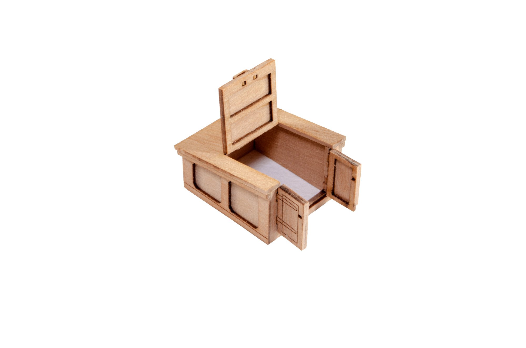
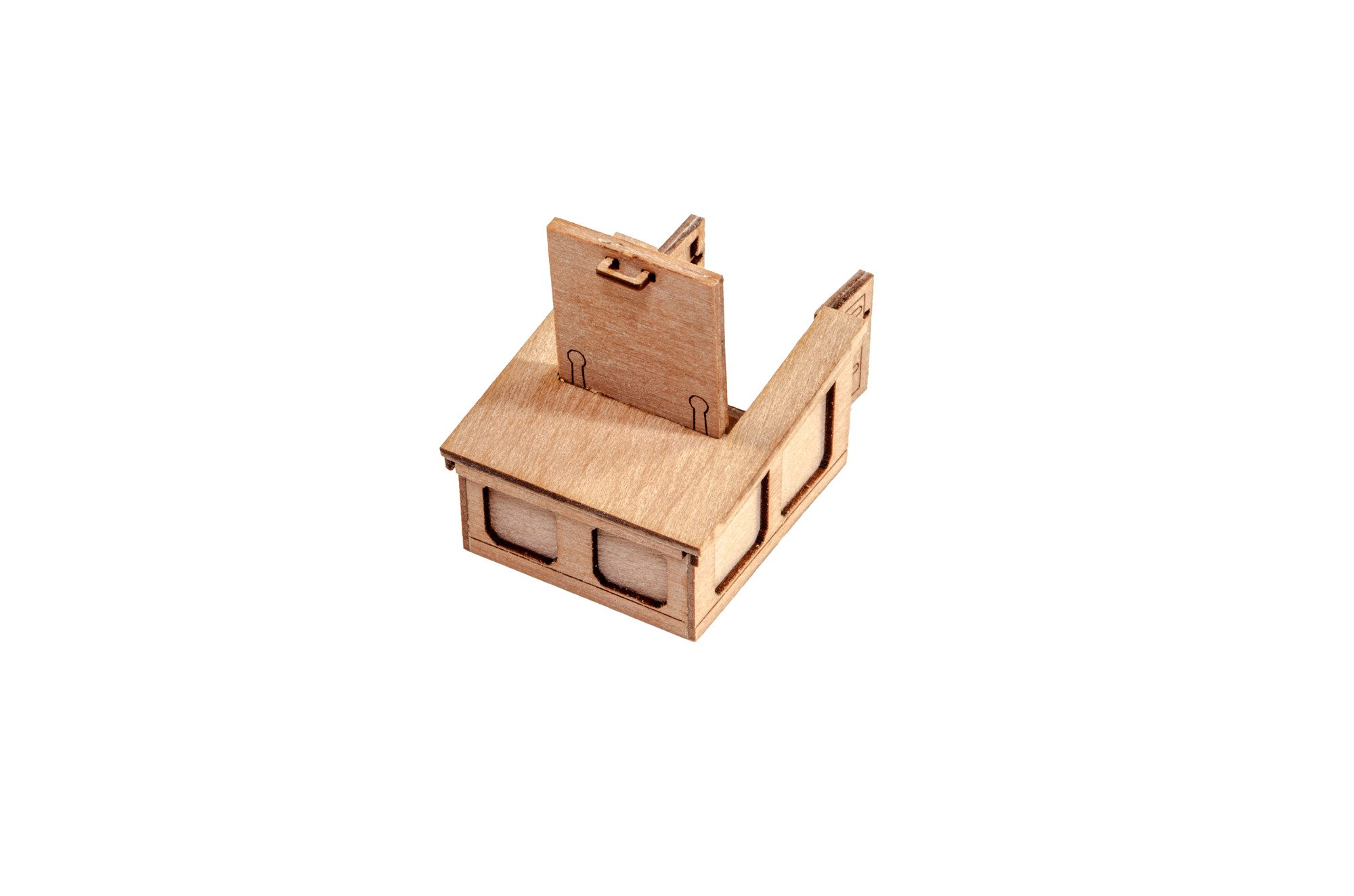
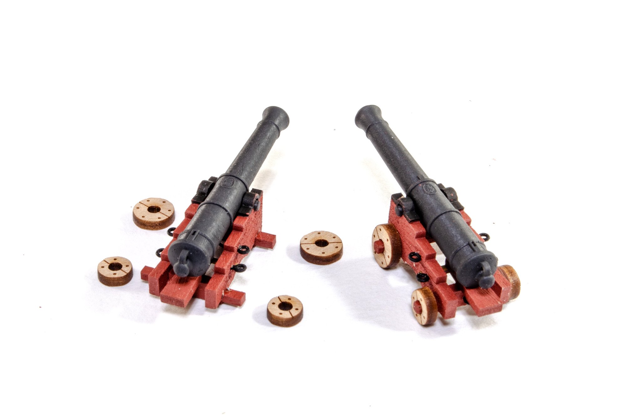
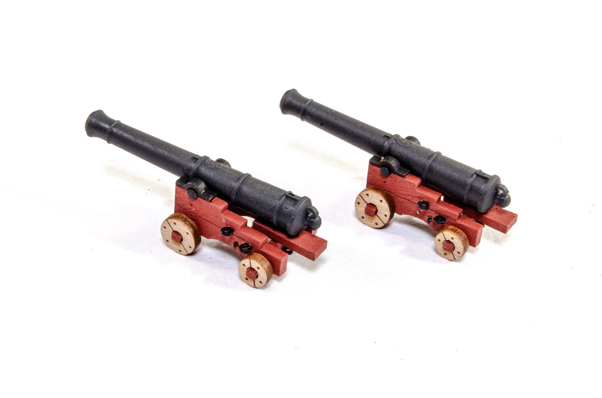
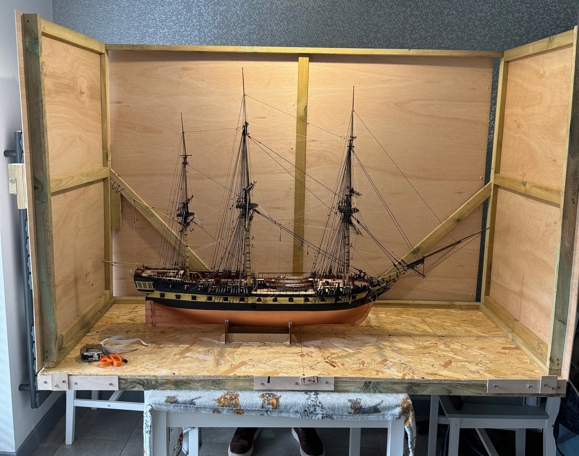
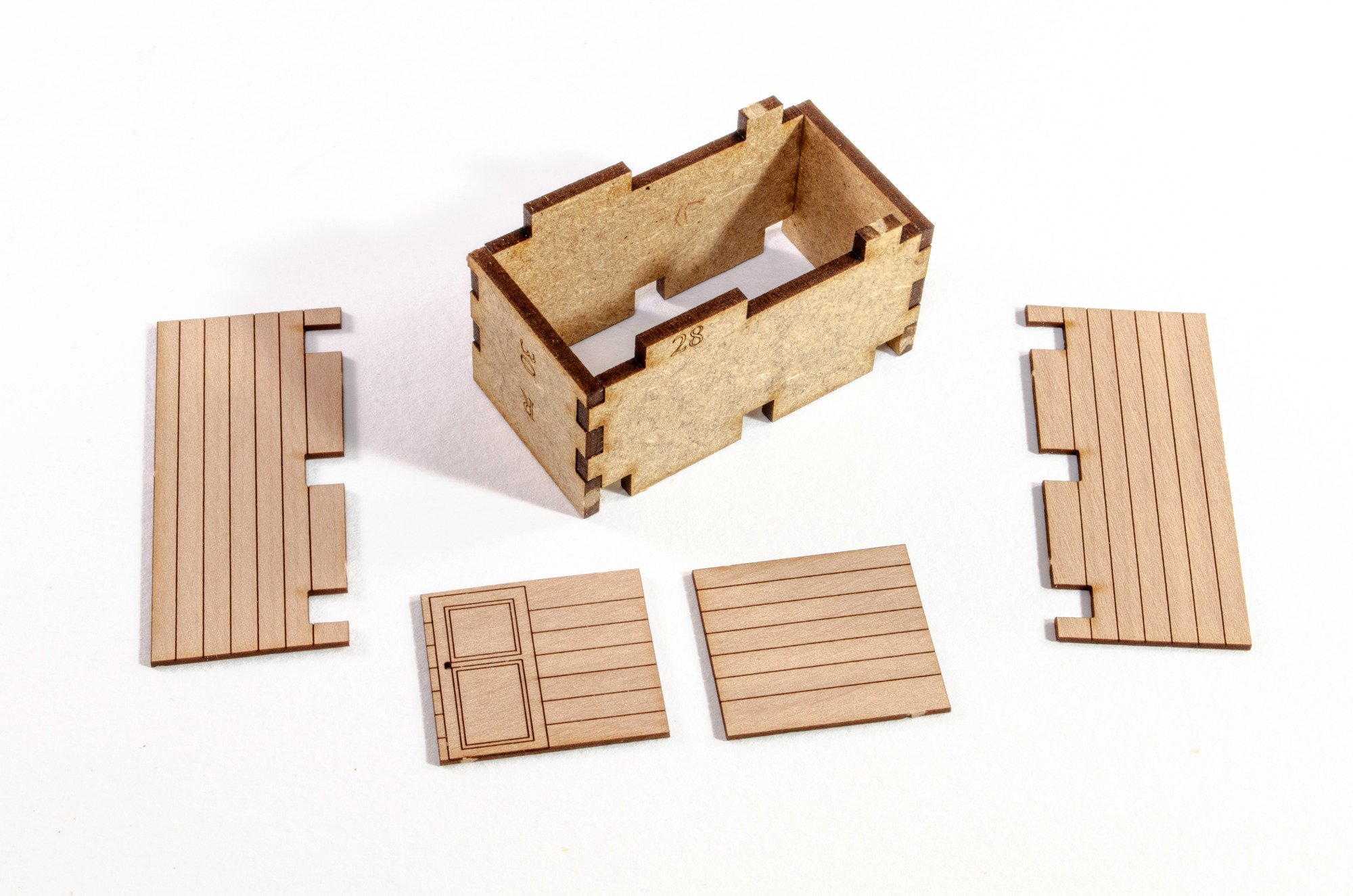
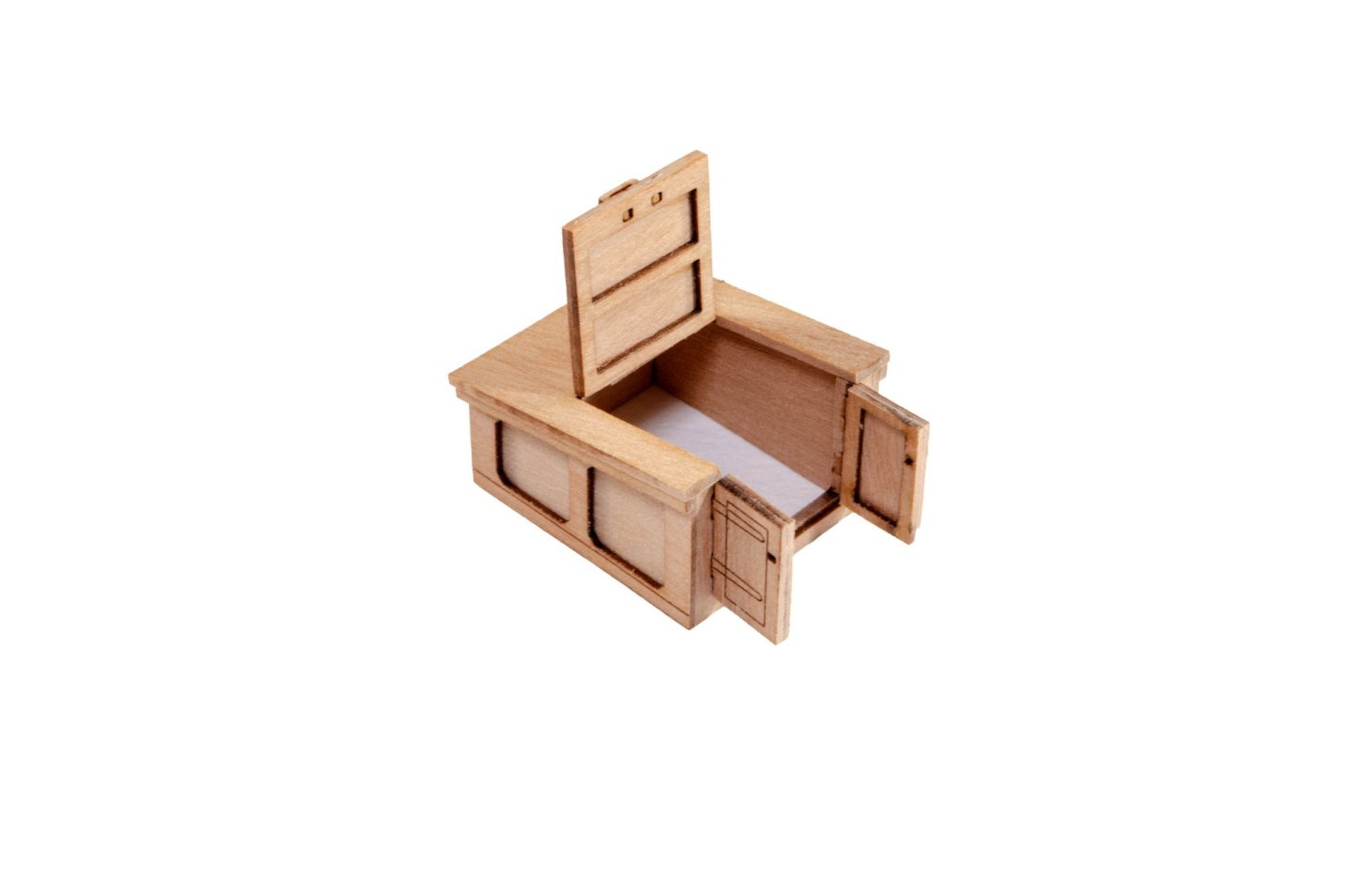
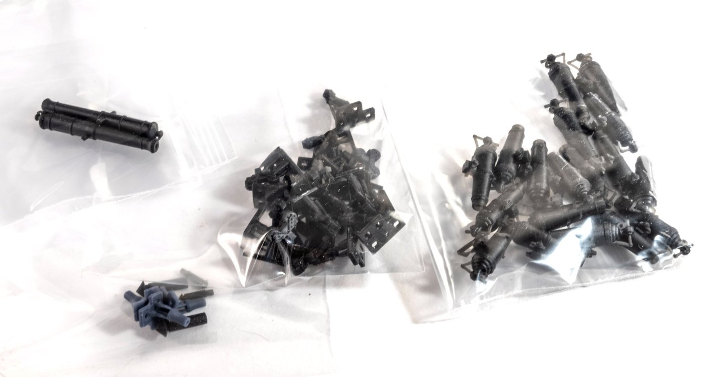
Building these models rarely means that anything is built in chronological order. I need to best use my time to do other tasks while I'm doing some of the much earlier work. This has been the case for Harpy. Since the last work, I was unable to do anything with any significant sanding work due to HMS Indefatigable still occupying most of my workspace. Thankfully, this weekend, Indy has been moved to her shipping crate, pending her journey to her new home in Scotland. So while Indy was still outstaying her welcome in my workshop, I've started to build a multitude of other things. Here are just three of the items I've been working on in that time.....the carronades, cannon, and companionway. These guns build in exactly the same way as those on previous models. The companionway is a little different and looks very nice with her inlaid panels. The lid is just tacked on while the PE is primed and painted. Not sure if I should paint the companionway yet, or leave in varnish. Ok, time for TV...


- 76 replies
-
- 29
-
-
-
- Harpy
- Vanguard Models
- (and 1 more)
-
Outstanding! Your best yet! Certainly imposing once the rig is done.
- 587 replies
-
- 3
-
-

-
- Indefatigable
- Vanguard Models
- (and 1 more)
-
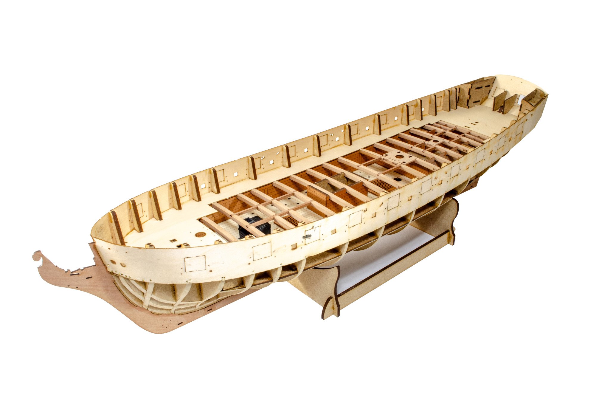
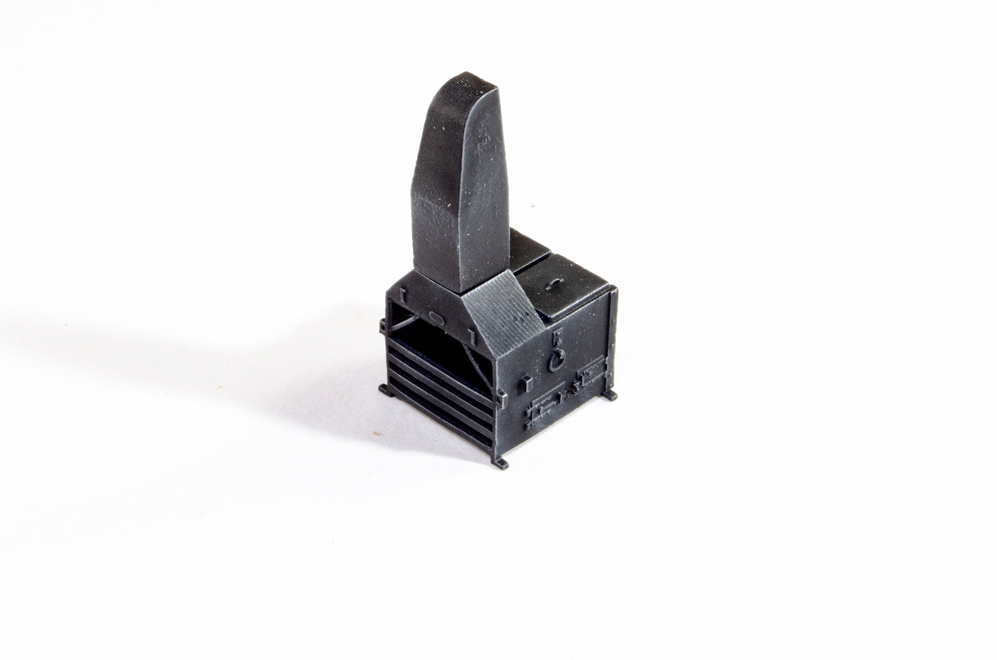
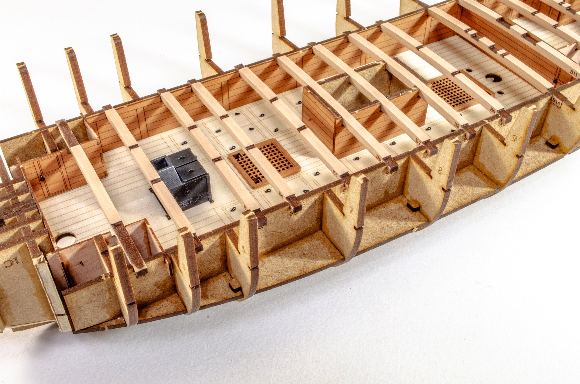
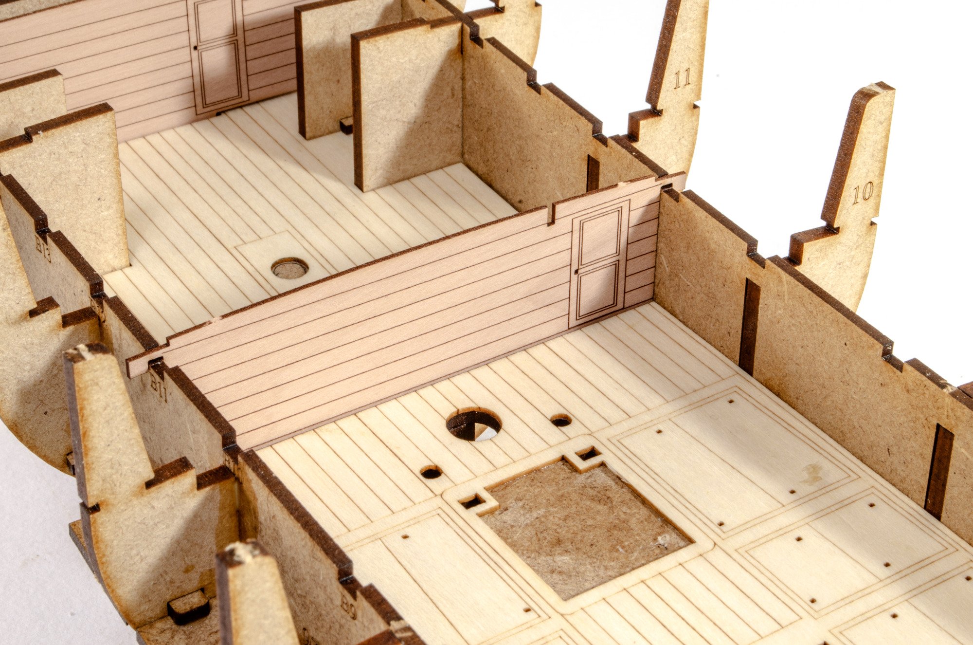
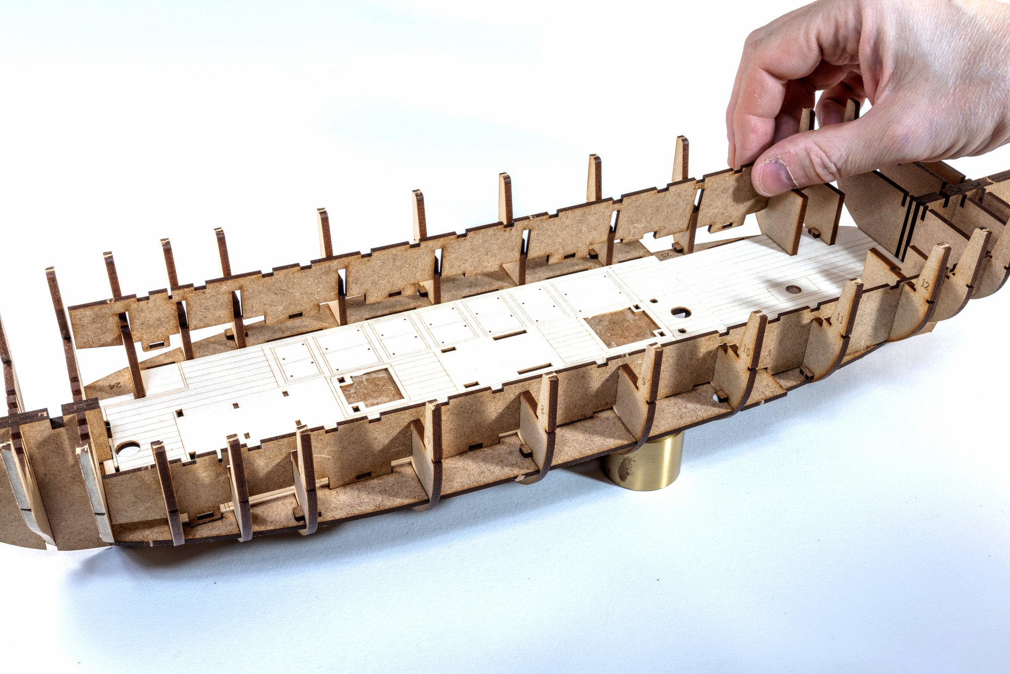
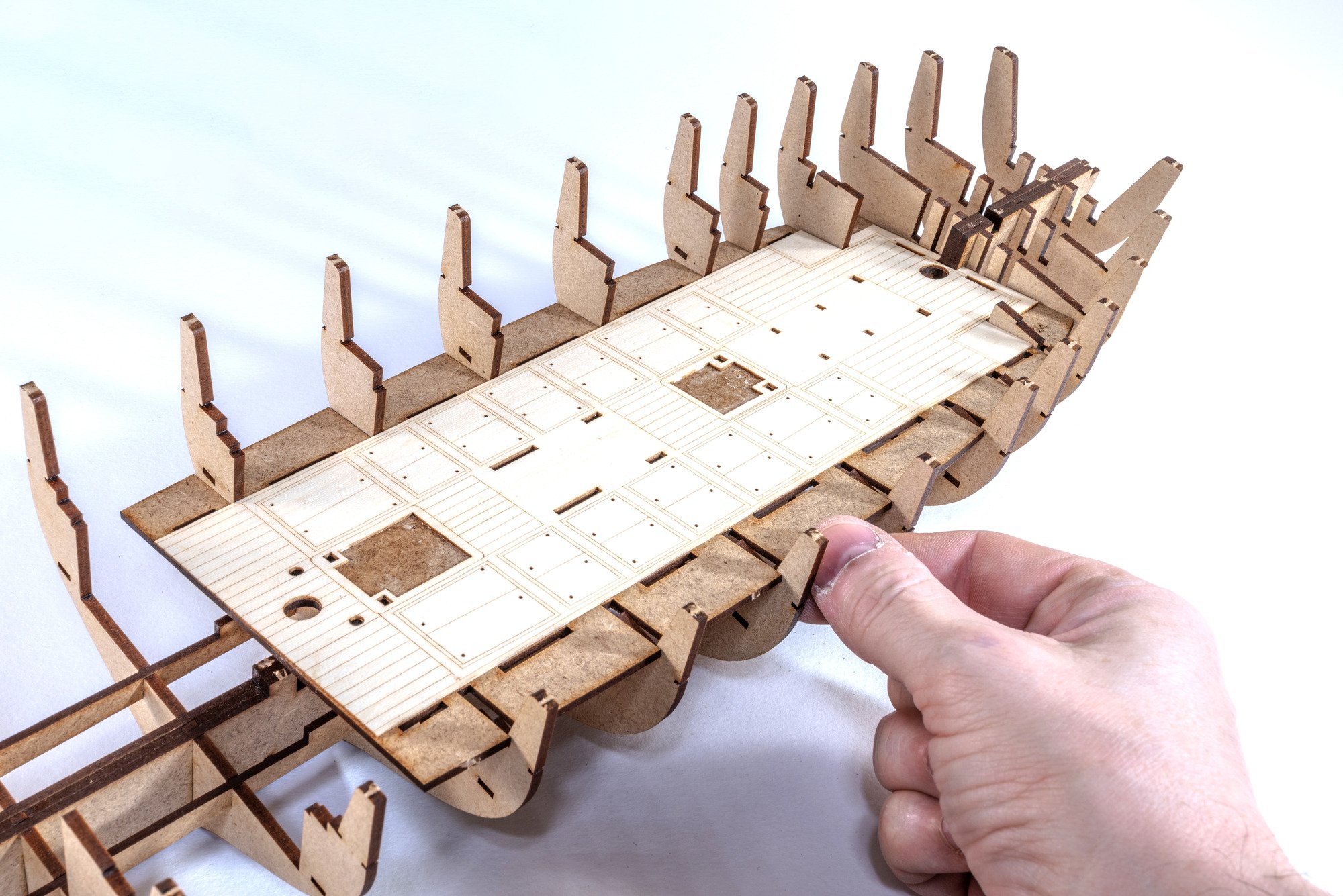
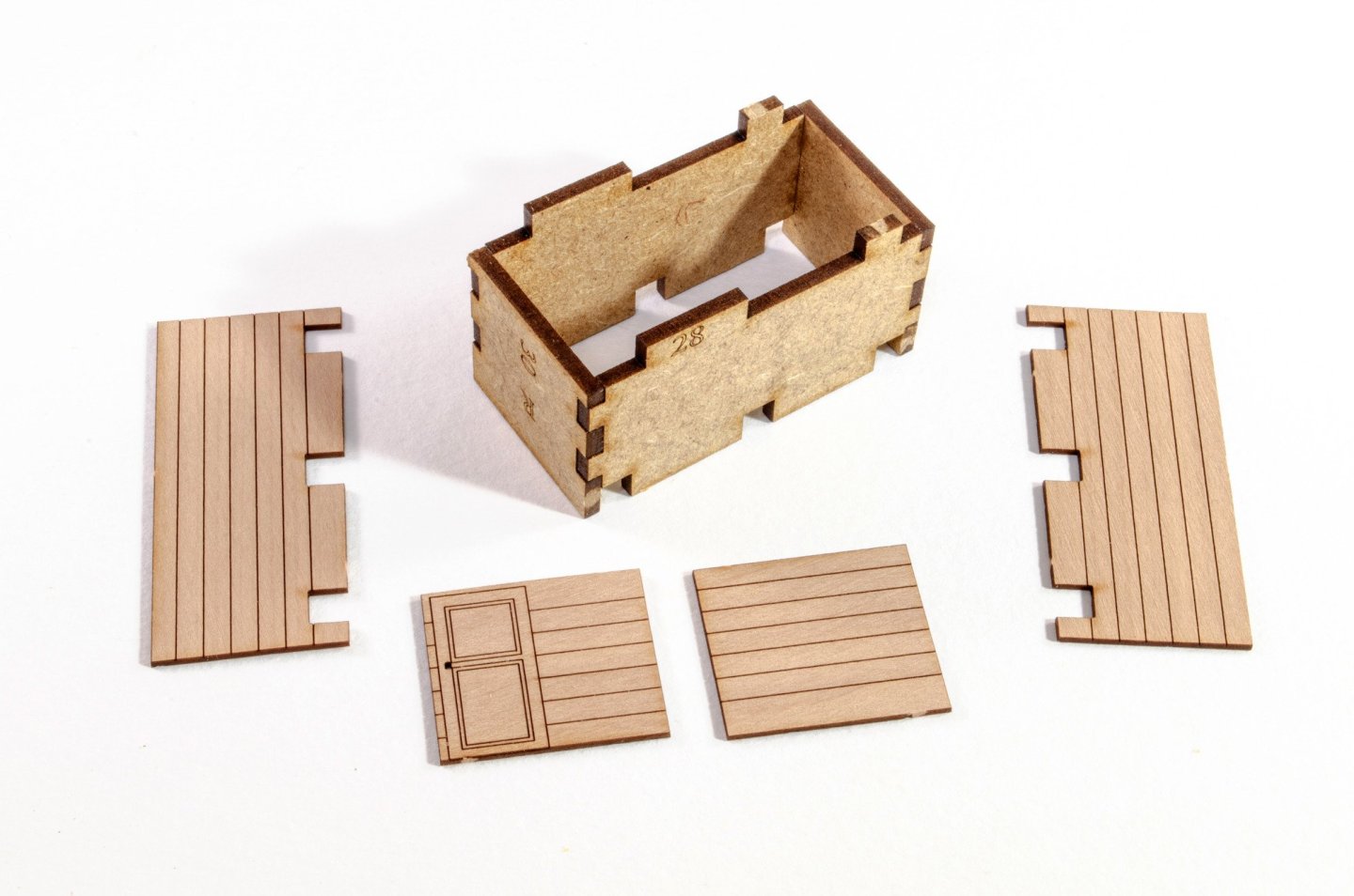
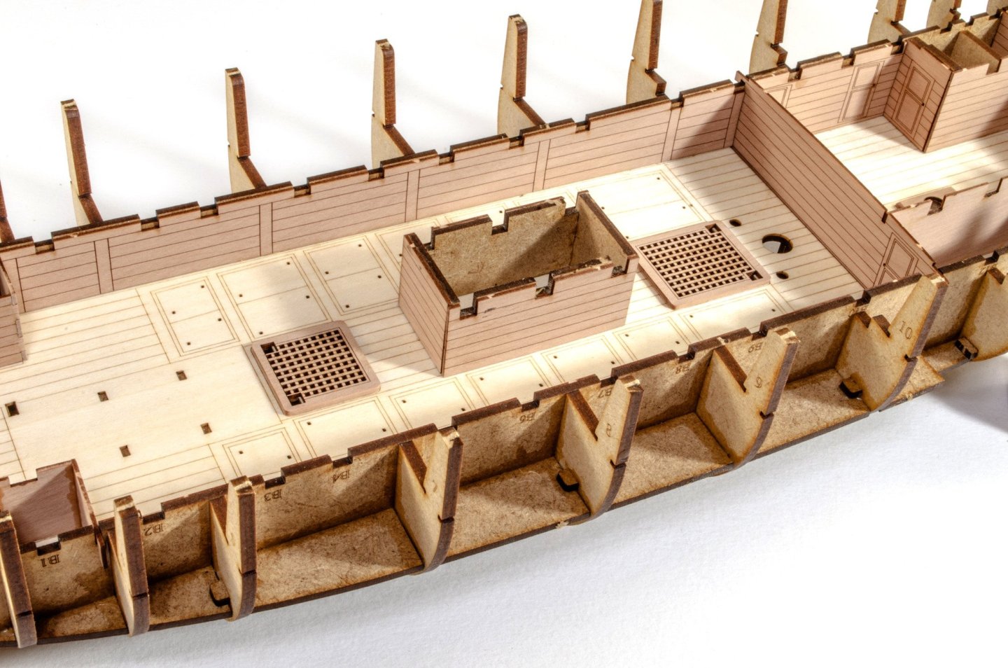
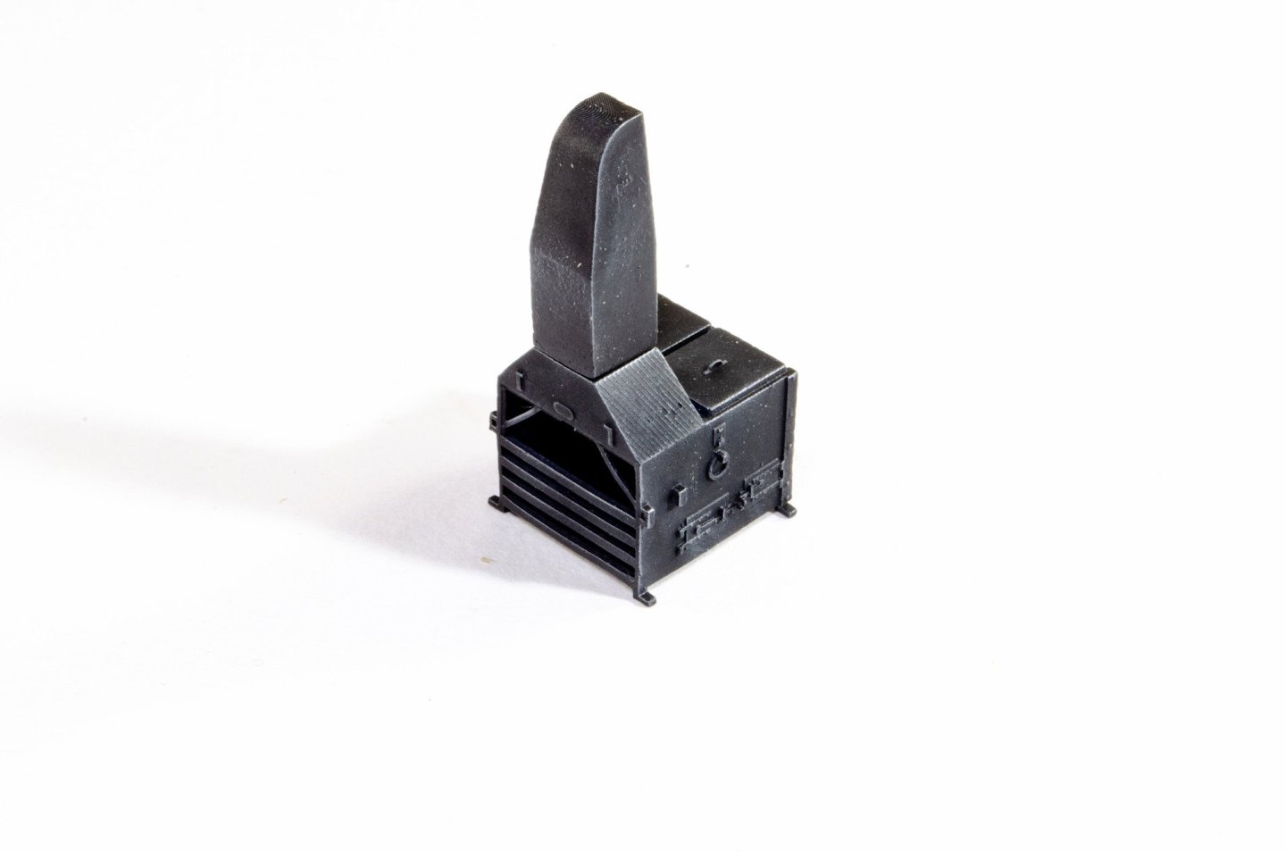
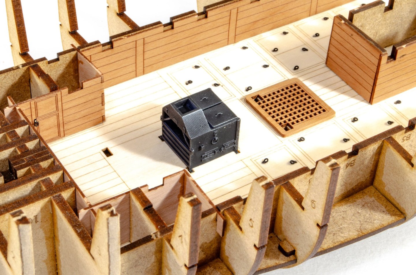
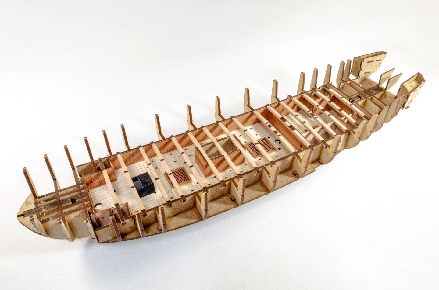
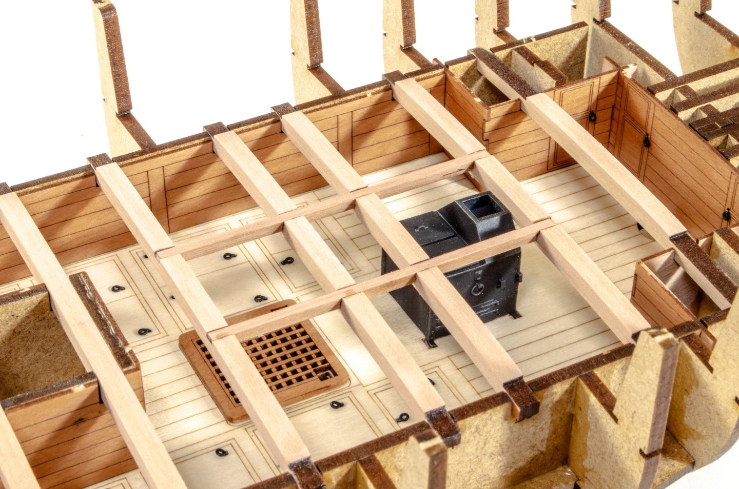
And the last for tonight... More deck details. Here is the sail room. I did make a slight mistake and added the door side to the wrong end. I'll note that in the manual. A brand new design stove is supplied as two parts in 3D print. No PE needed for this. I painted it black, added flat varnish, and then some steel pigment. The chimney is only on for display. It won't be glued yet. The stove body is now glued into place. Eyelets are also added for the door handles and hatches. All deck beams are now fitted. These are numbered and simply plug into the numbered slots on the lower deck side walls. Various support beams etc. are now also glued into place. Lastly, the 0.8mm ply deck is flexed and slipped into position. Zero effort to do this. Very easy. The deck and beam assembly has been changed from other designs in that it is now totally flush with the top of the beams. This means that when the engraved deck is fitted, it's all you'll see through the deck cutouts.....no ply underlying. Time for wine...


- 76 replies
-
- 32
-
-
-
- Harpy
- Vanguard Models
- (and 1 more)
-
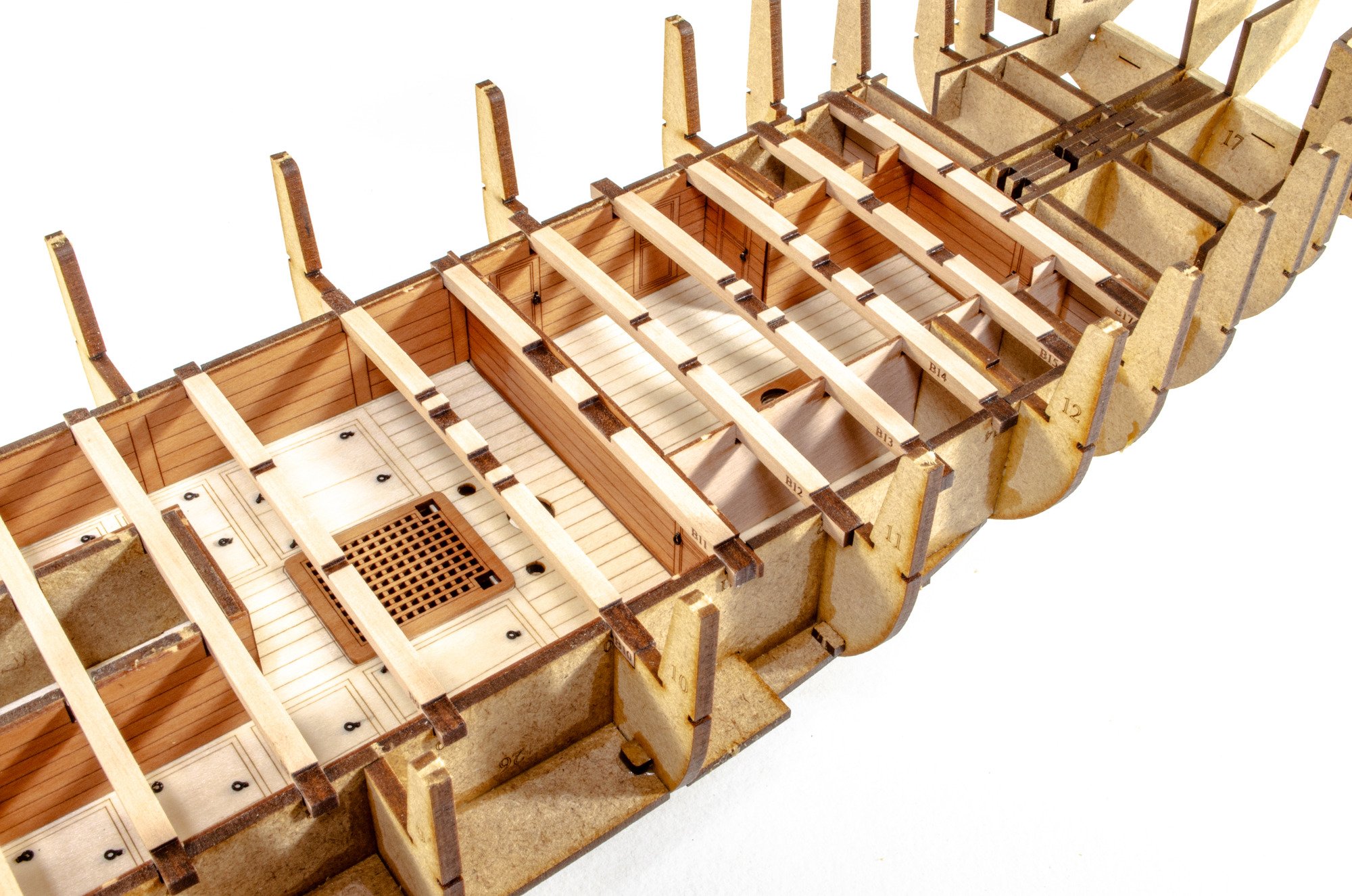
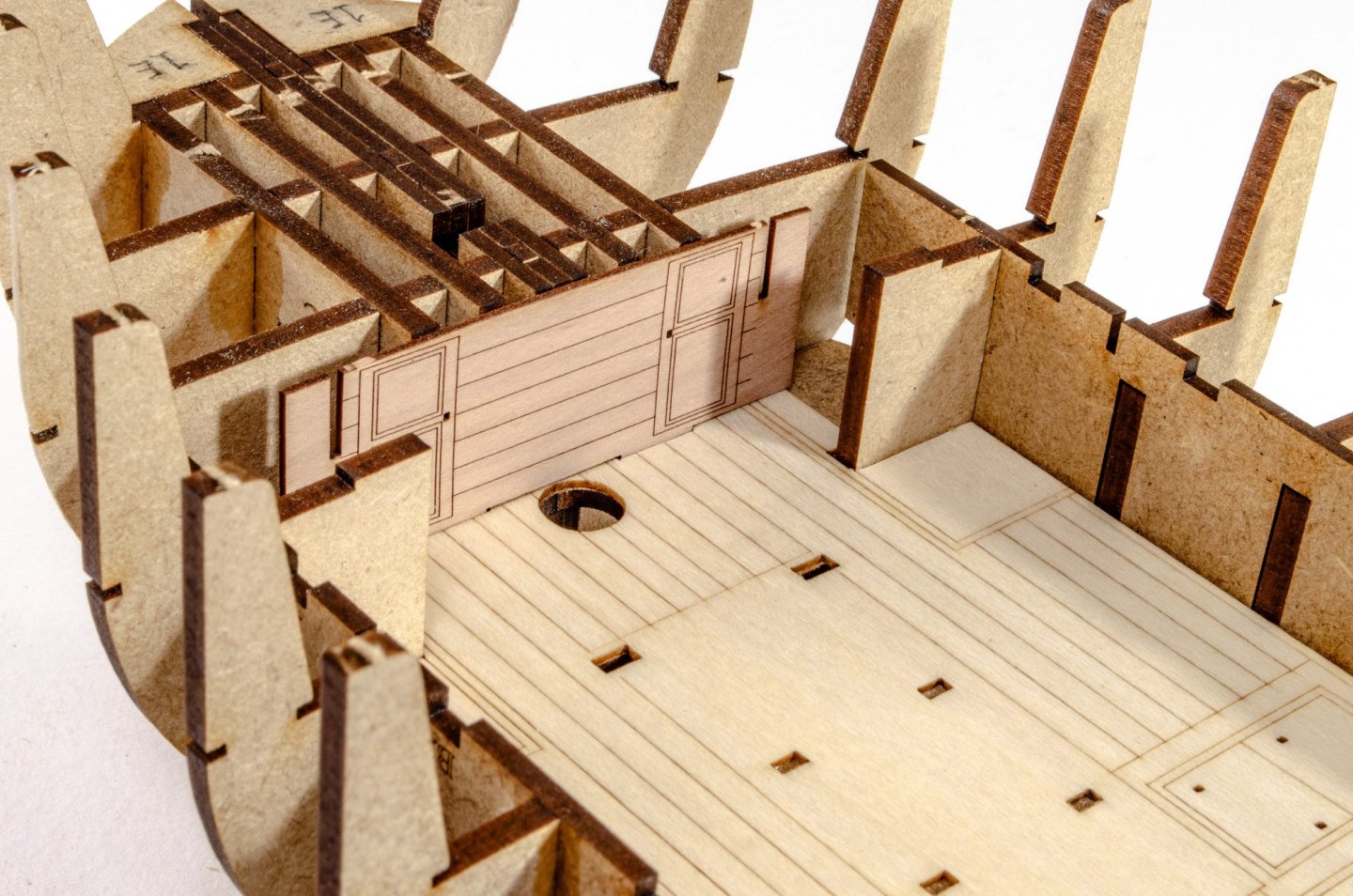
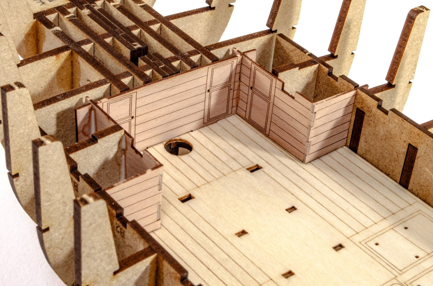
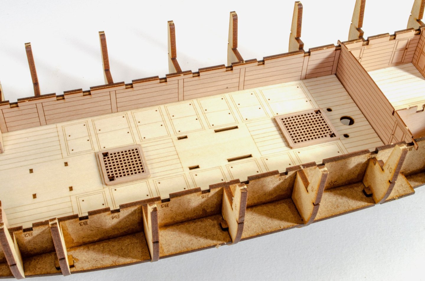
more... The stern assemblies are now slotted into place and bulkhead #17 is glued....yes, glued! And once you've checked everything is nice and straight along the keel, glue is brushed into all the joints and pins and then left to thoroughly set. If you like detail, then Harpy has plenty. Here's the lower deck now getting a makeover. The first deck details to go in are the grates. The deck is etched to show the exact position of these.


- 76 replies
-
- 25
-
-
-
- Harpy
- Vanguard Models
- (and 1 more)
-
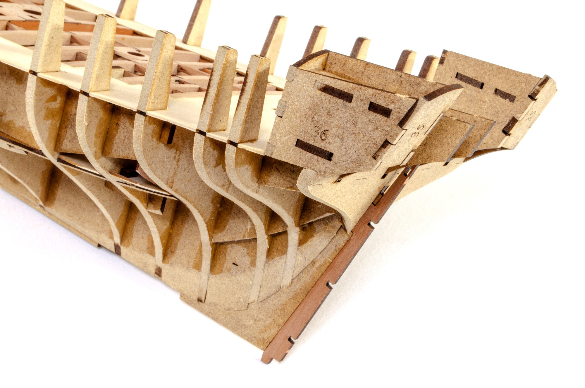
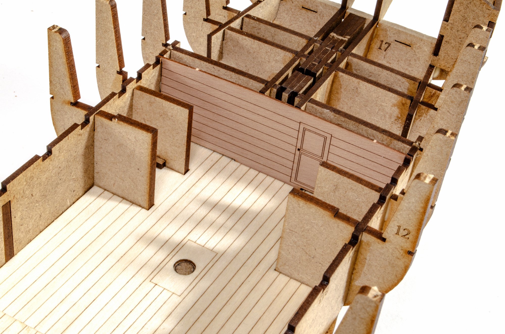
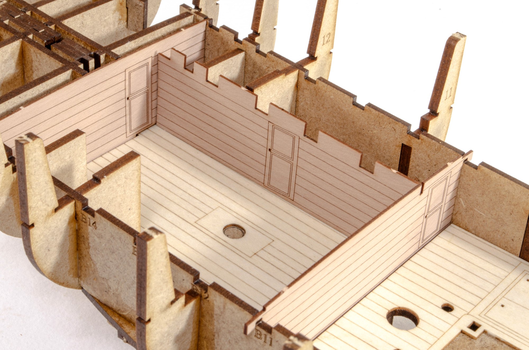
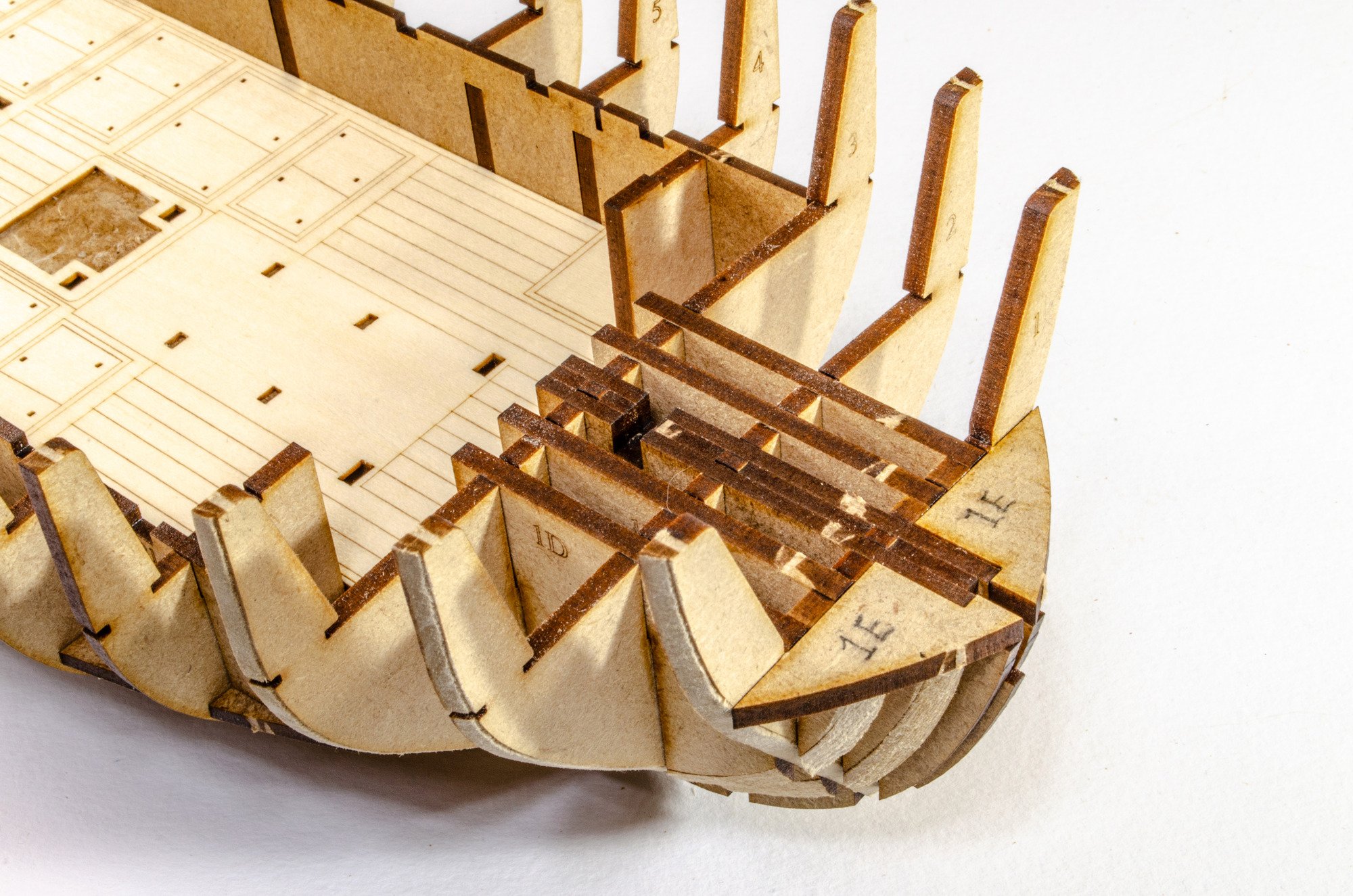
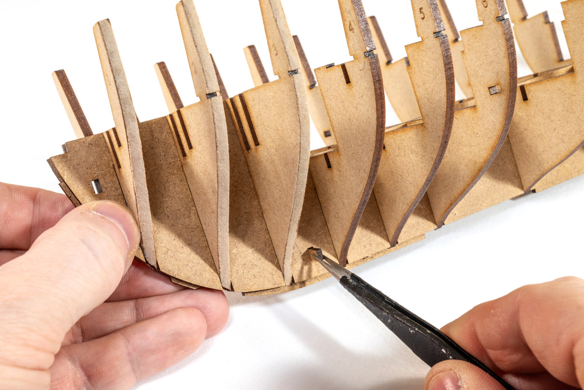
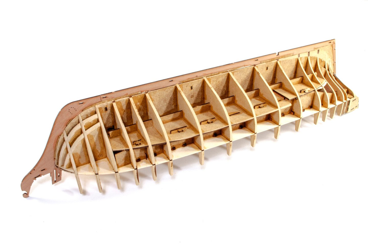
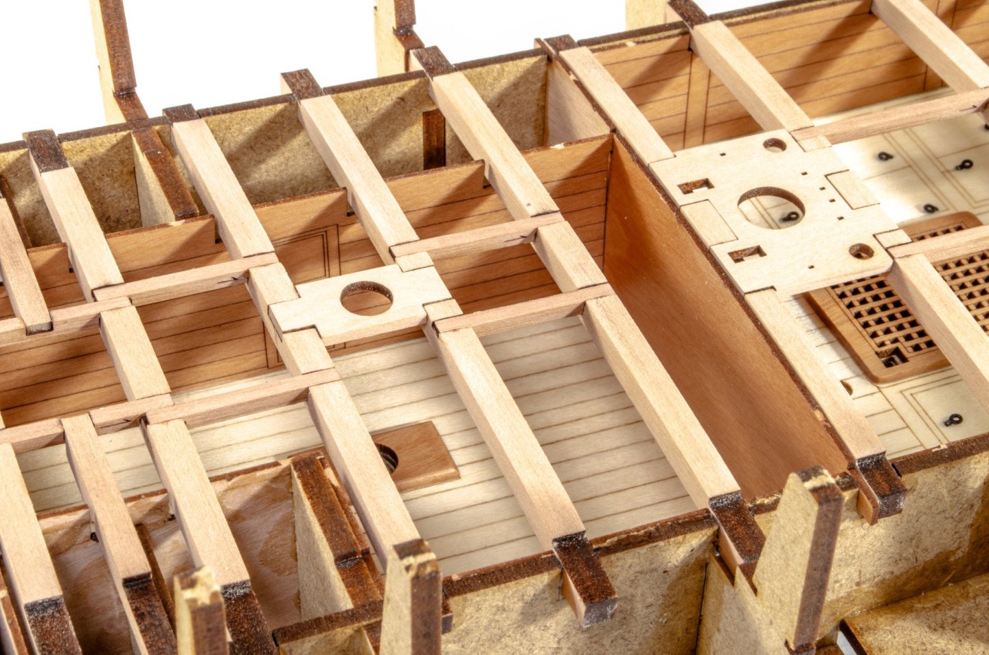
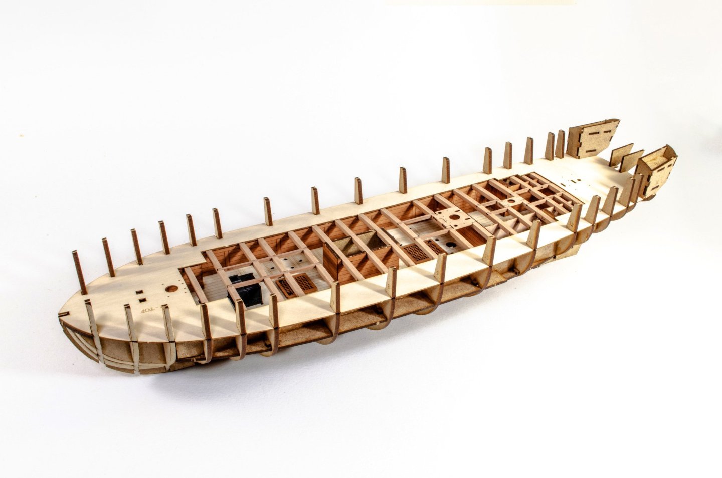
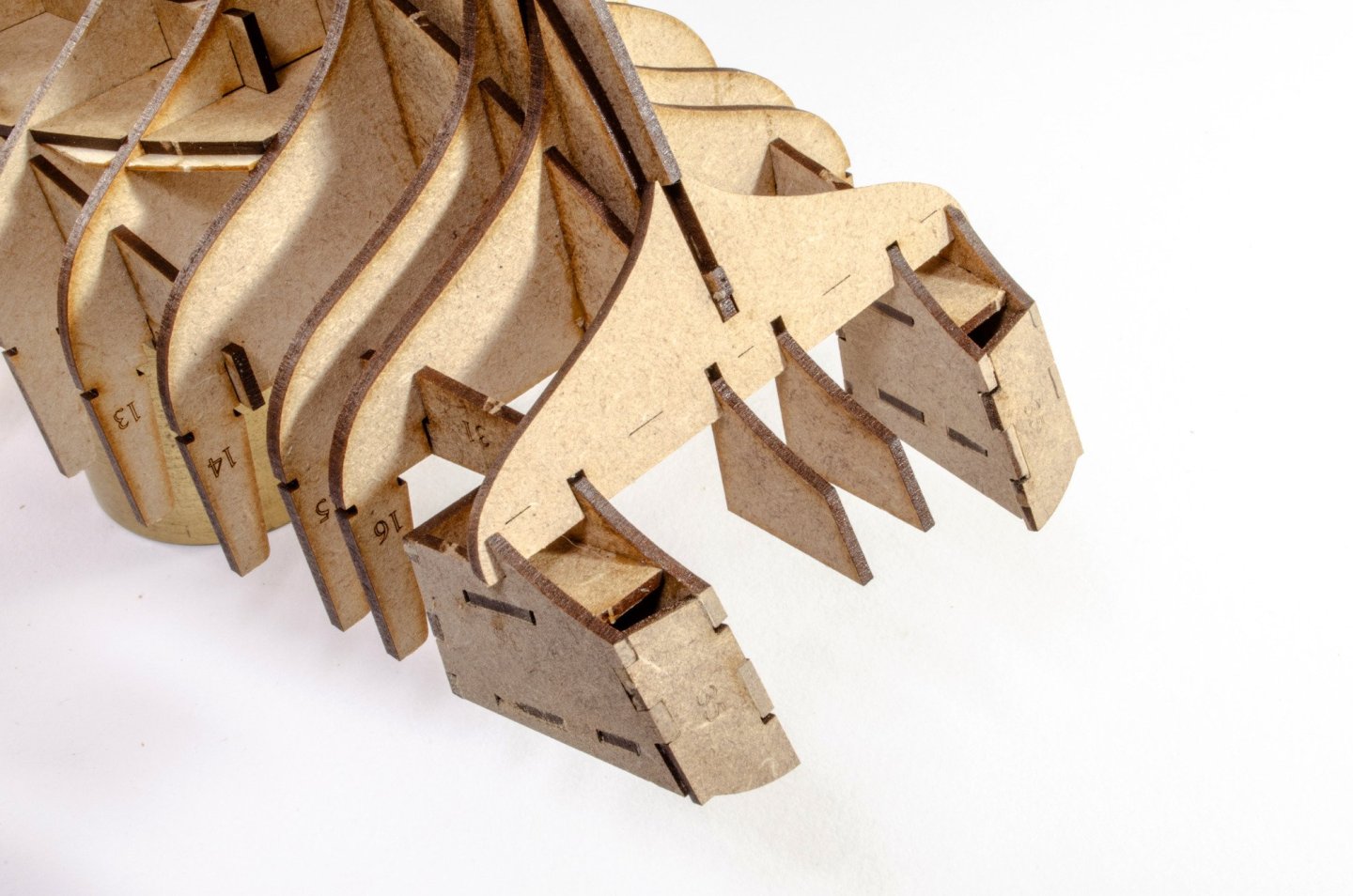
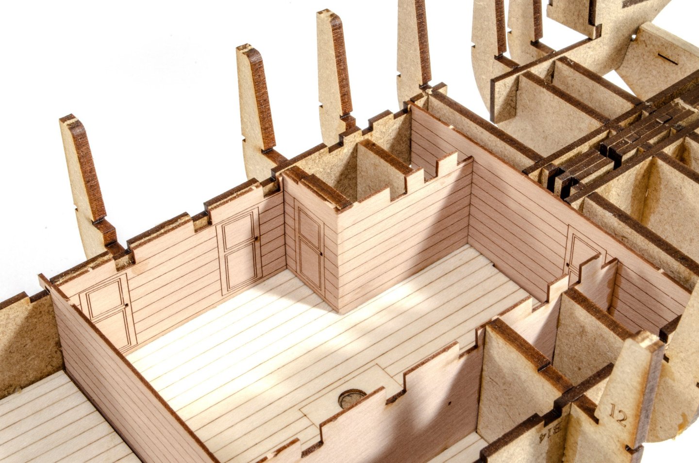
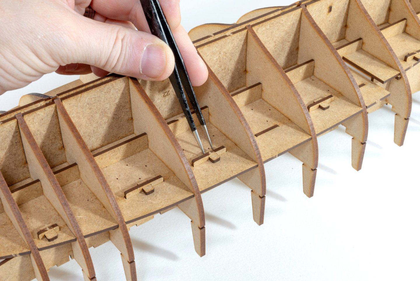
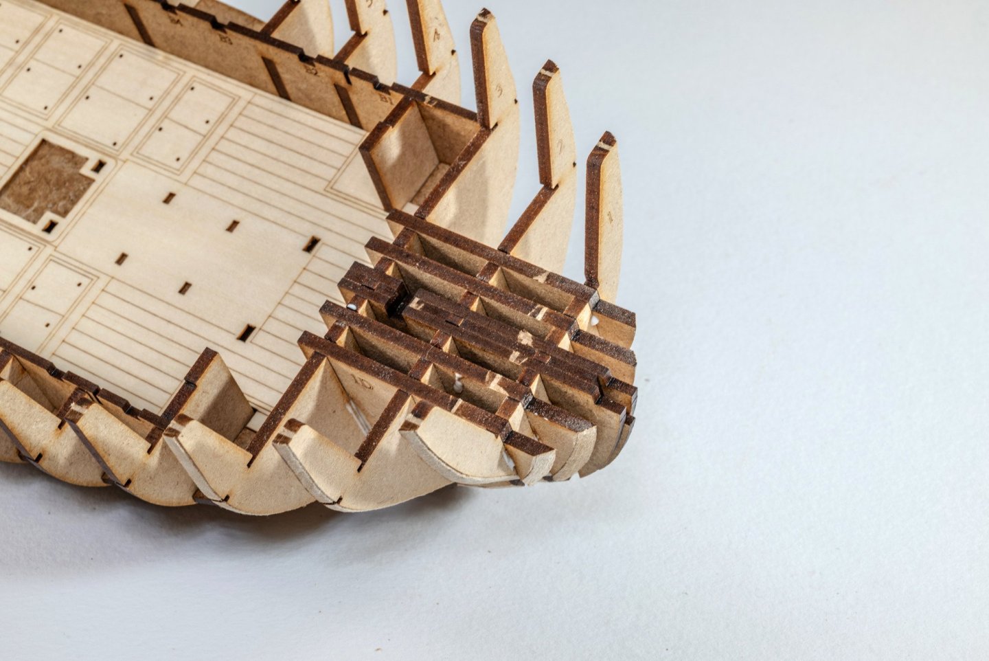
Continued... I now do the same with the rear lower deck, and again, pinned into place. I have glued the engraved decks to the MDF first as it provides a good opportunity to use weight to hold them flat while they dry, instead of using clamps. Now onto the lower deck sidewalls. Note that these are numbered for the eventual upper deck beams. Because of this, these are positioned so the engraved text is facing outwards. Once in place, more pins are used to lock these walls in situ. A series of formers are now slotted into the bow to help create the shape. These are bevelled before fitting. And now parts 1E are glued into position to create the beak of the main deck. Some glue is now used to build the stern cabins.


- 76 replies
-
- 27
-
-
-
- Harpy
- Vanguard Models
- (and 1 more)
-
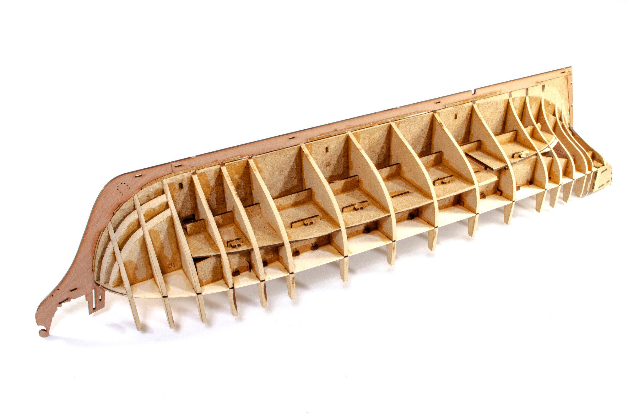
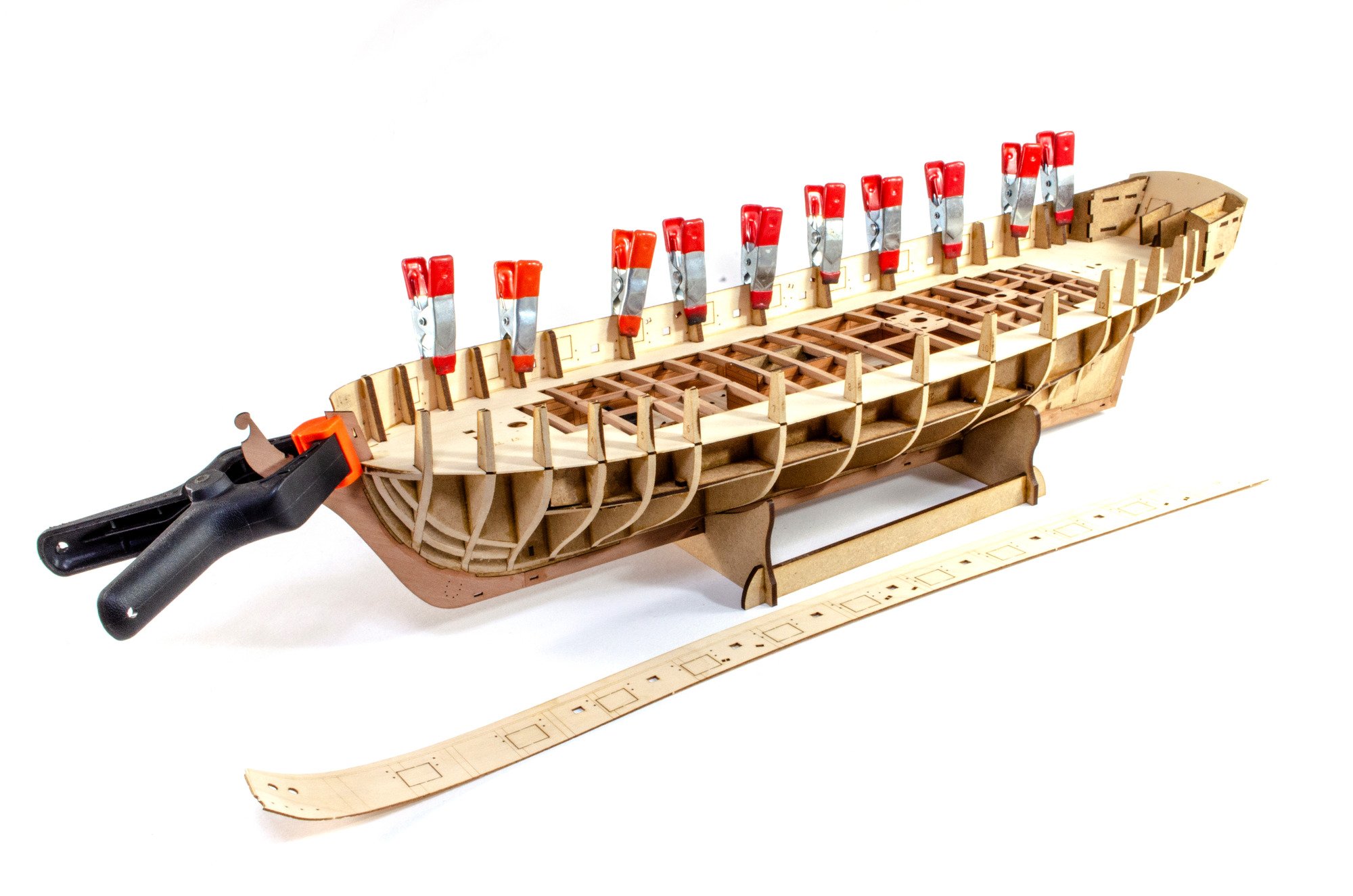
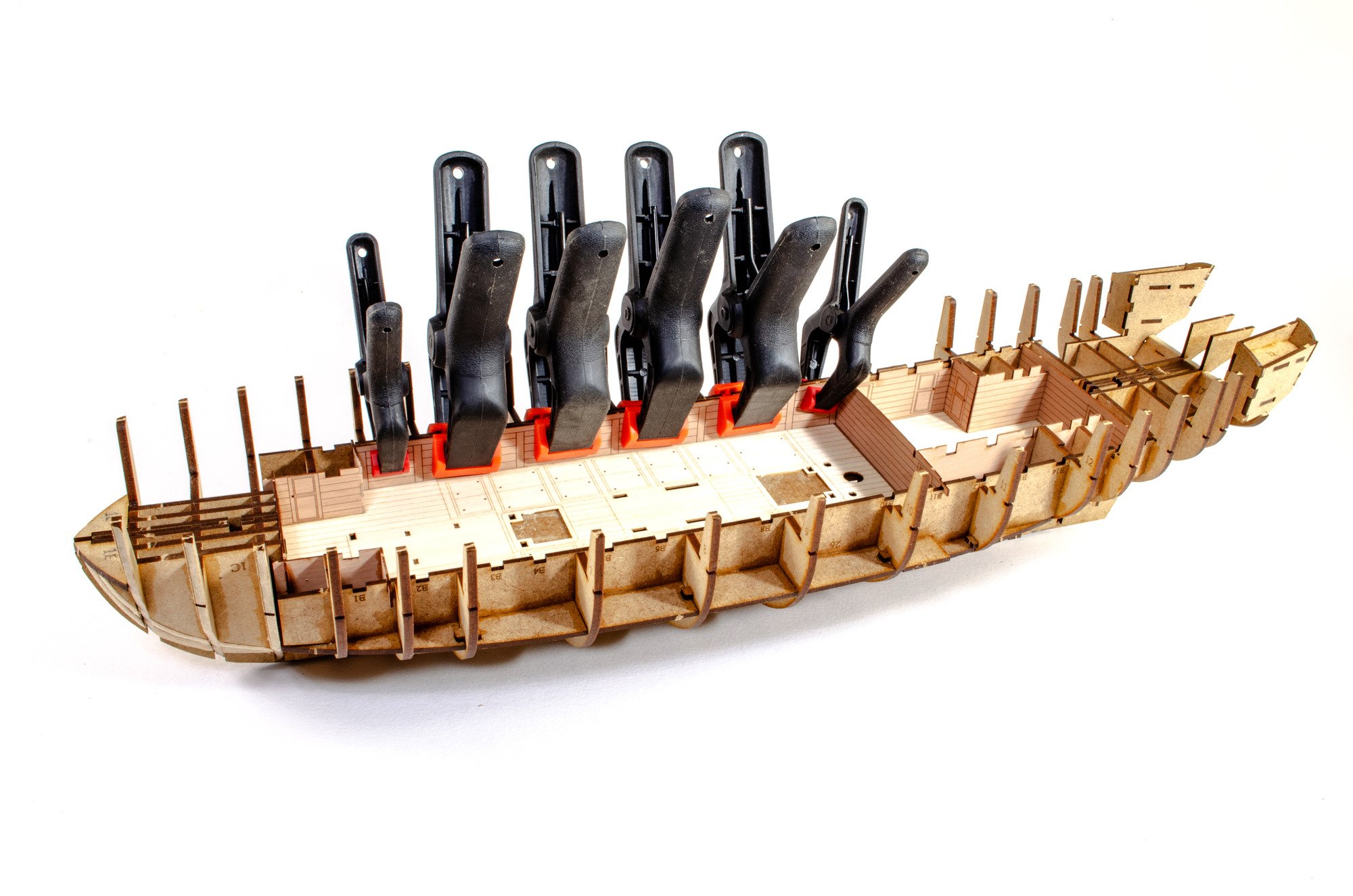
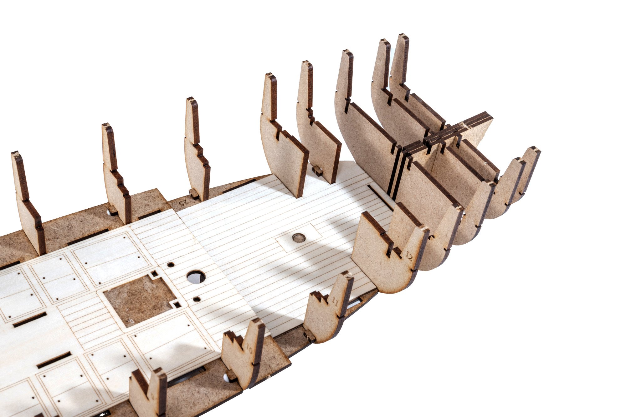
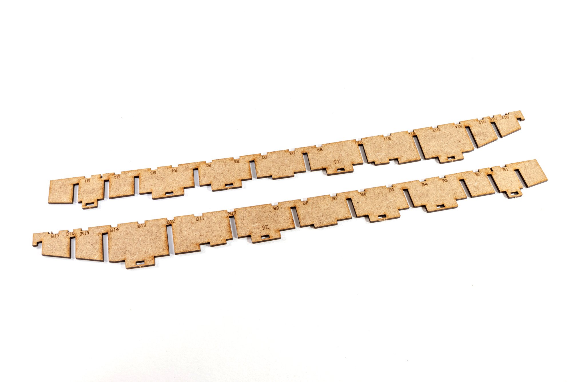
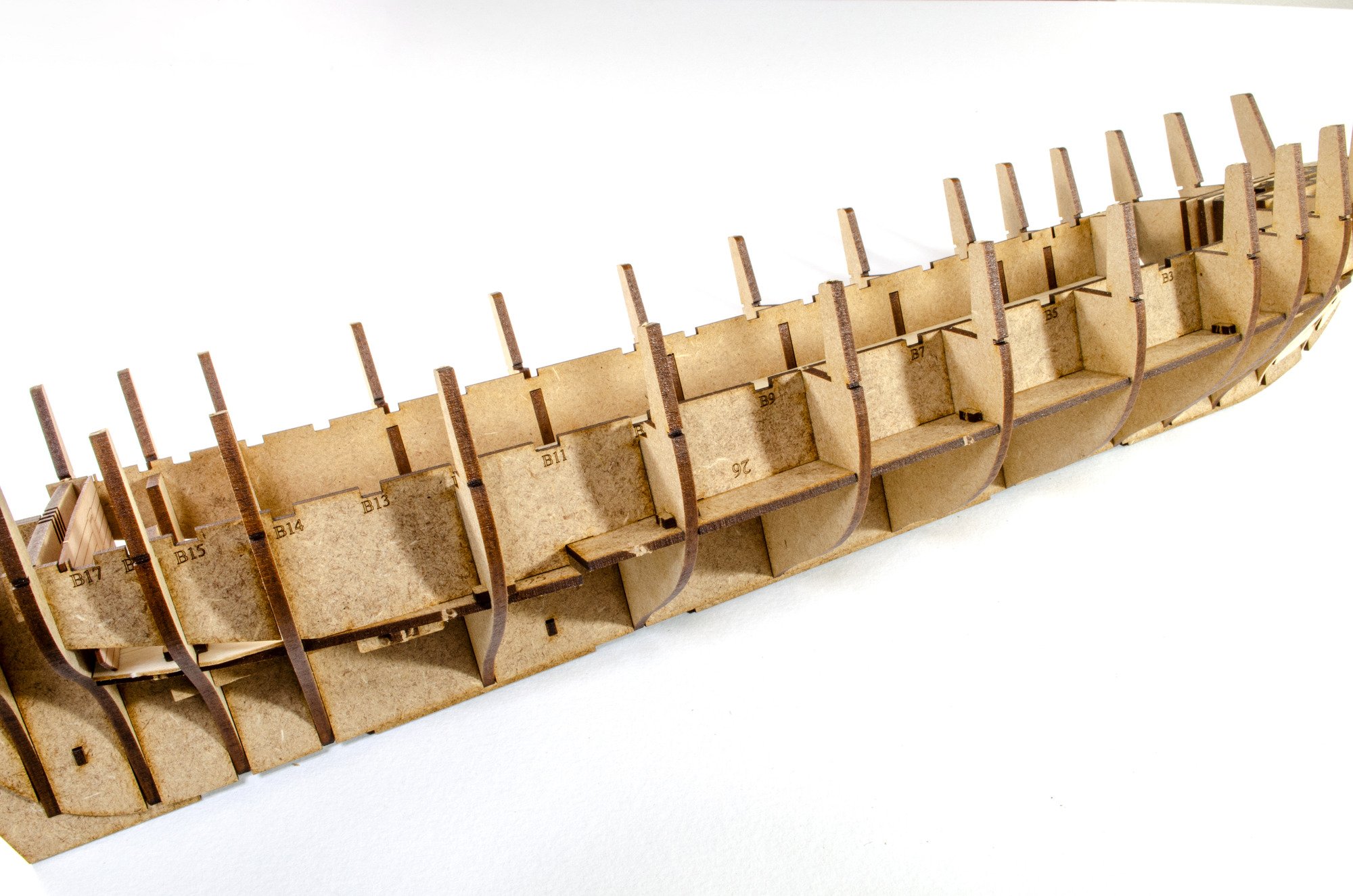
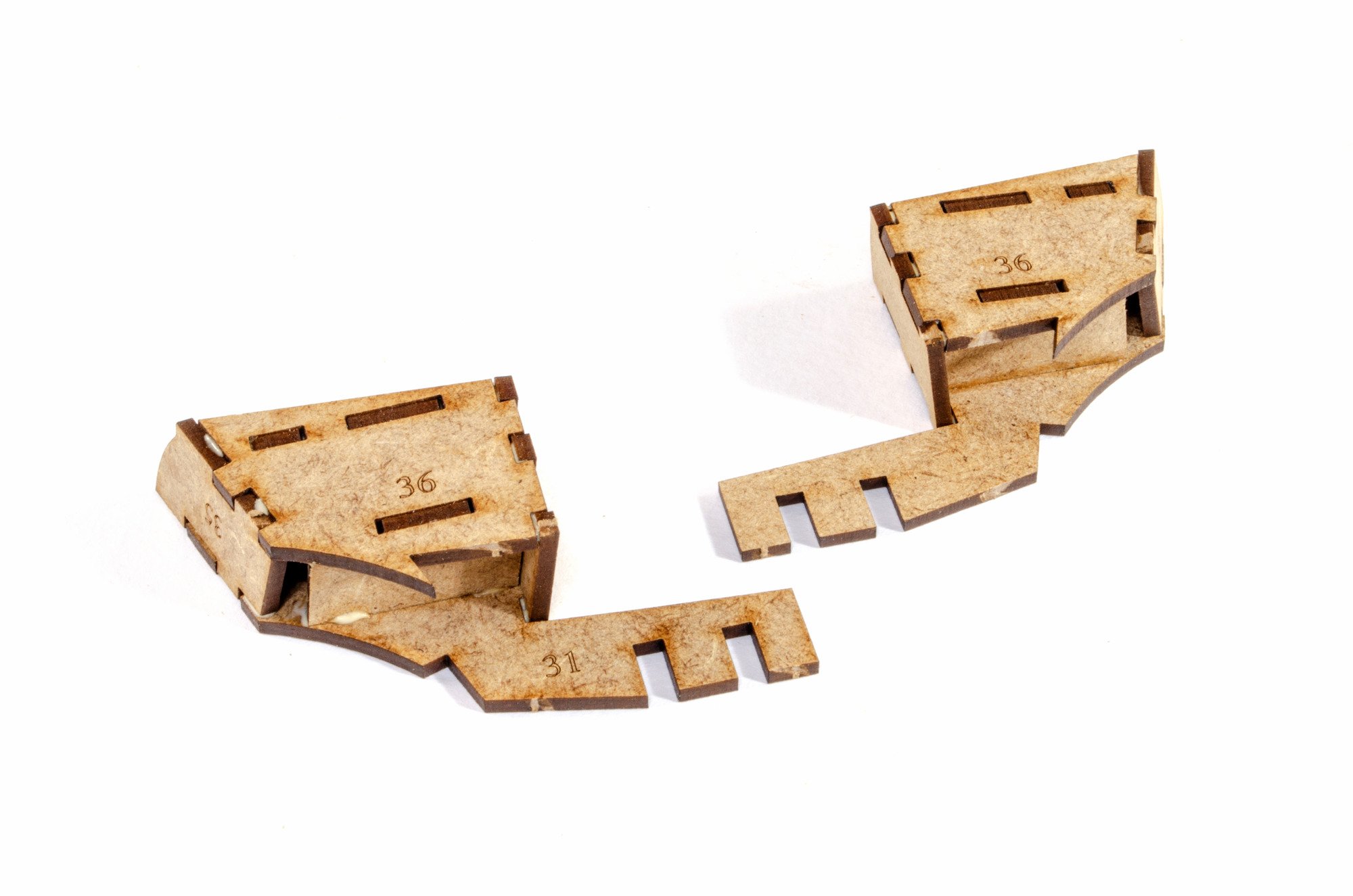
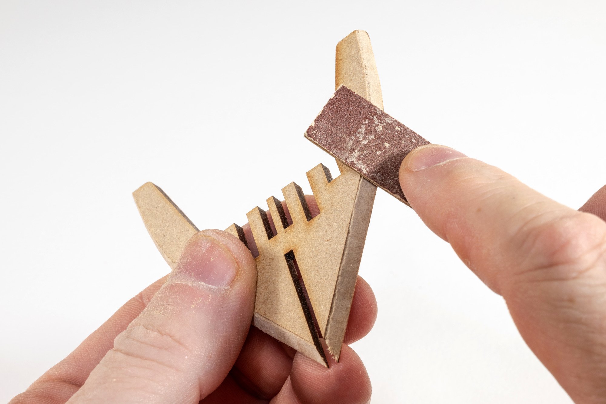
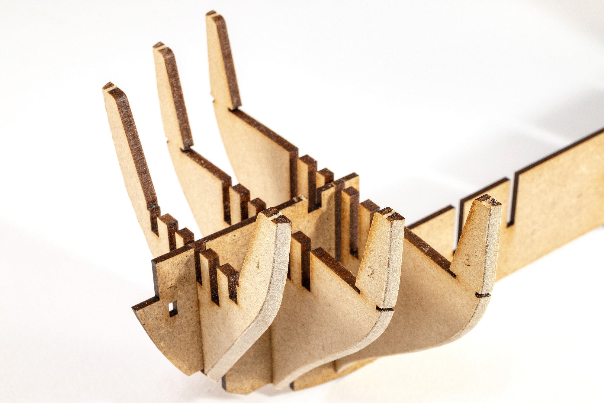
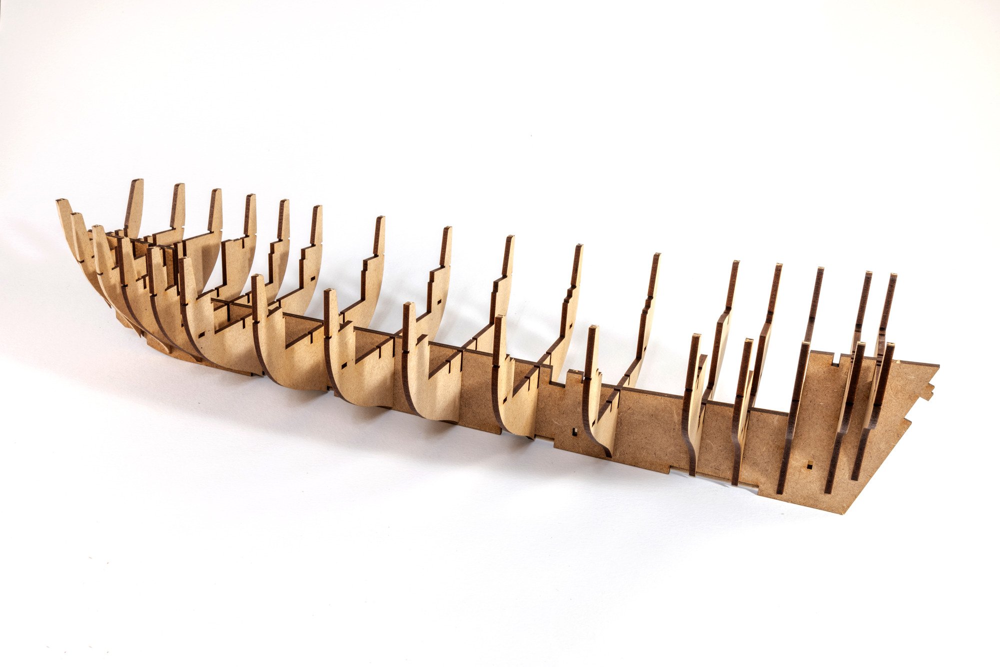
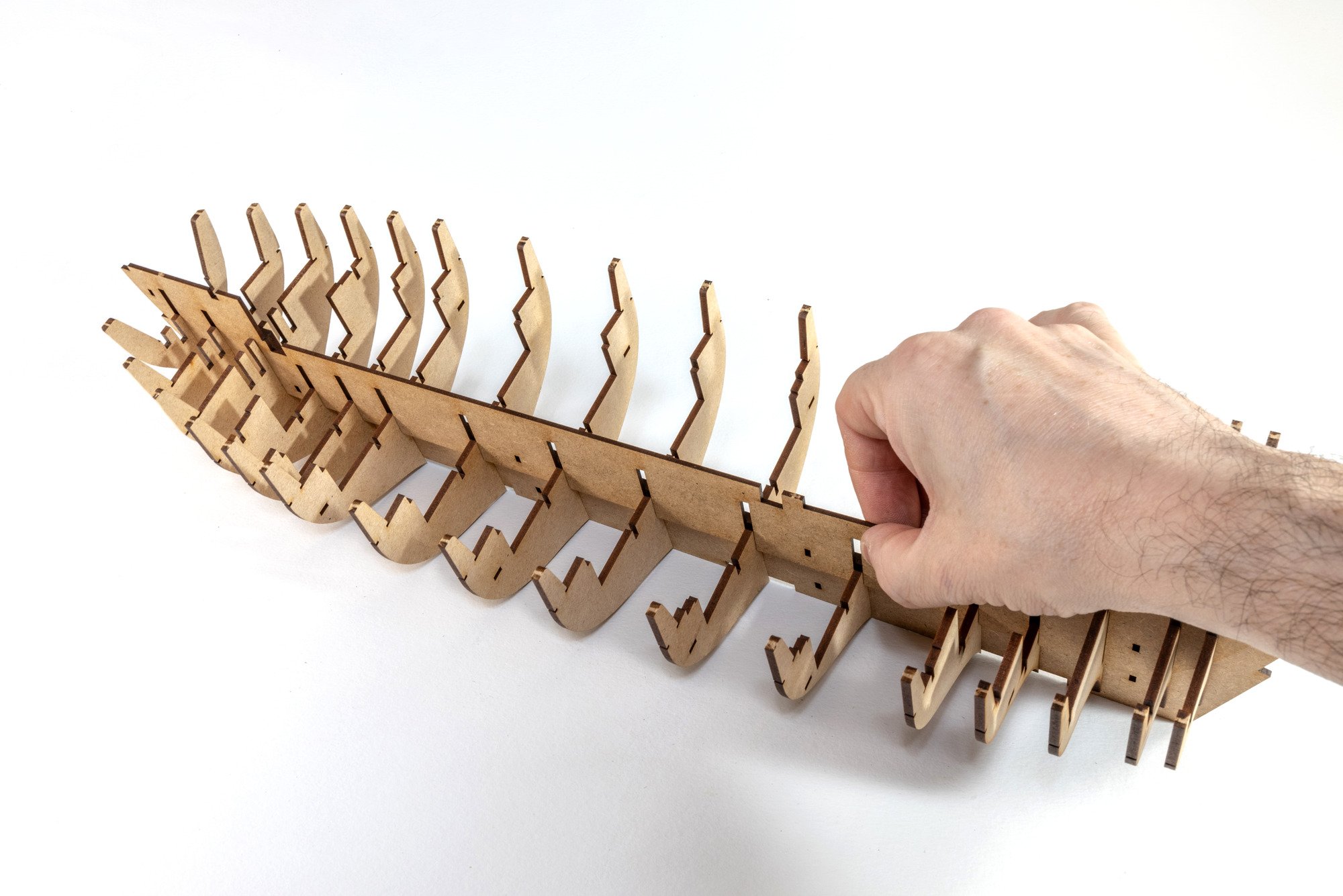
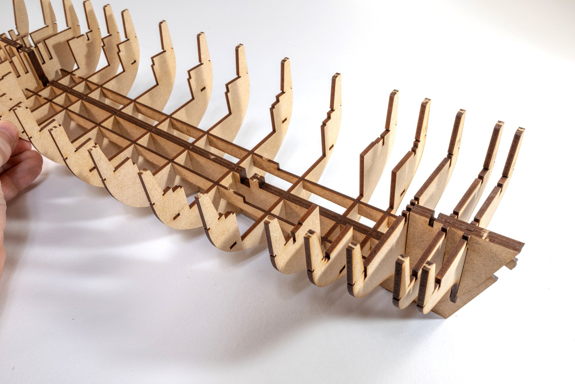
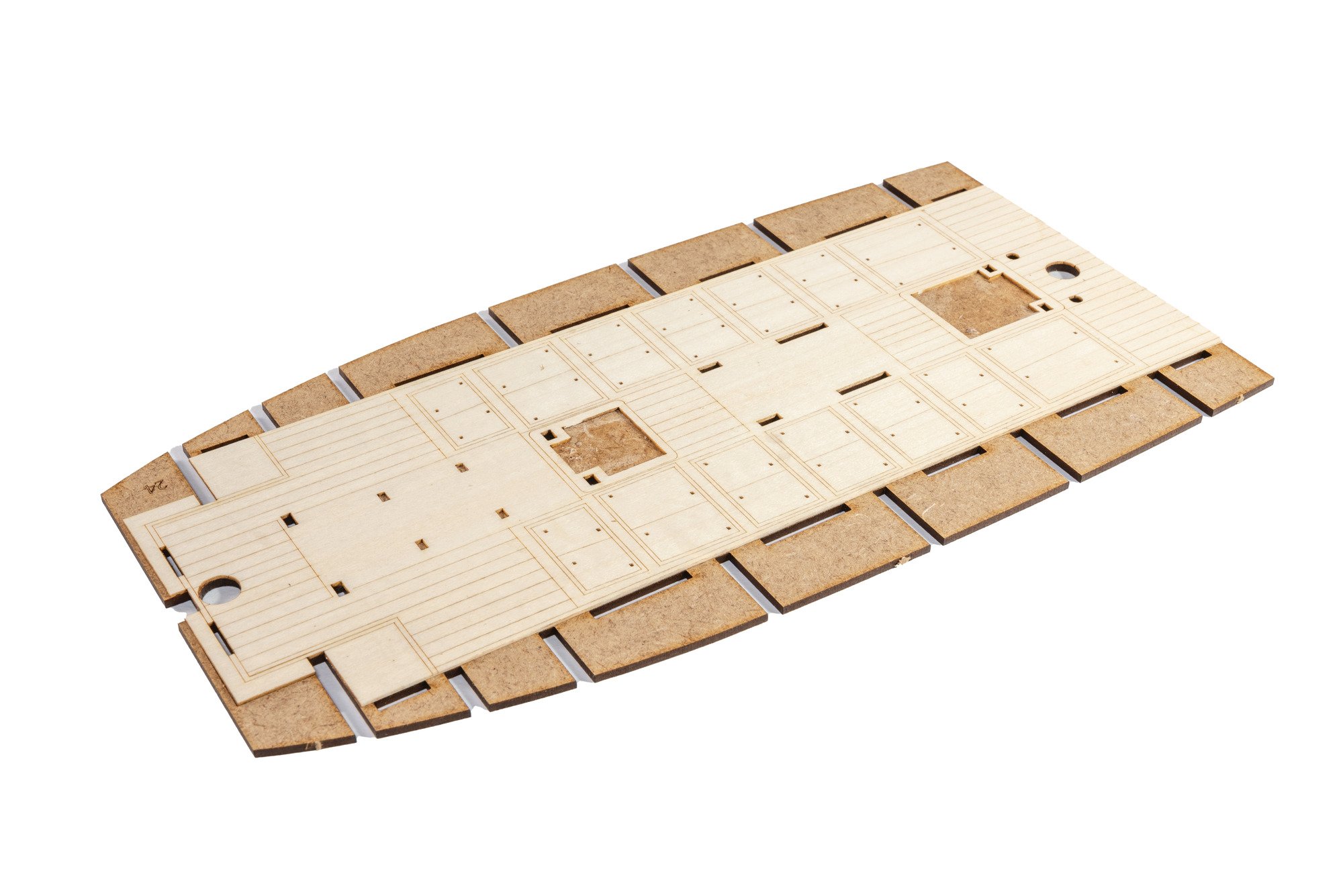
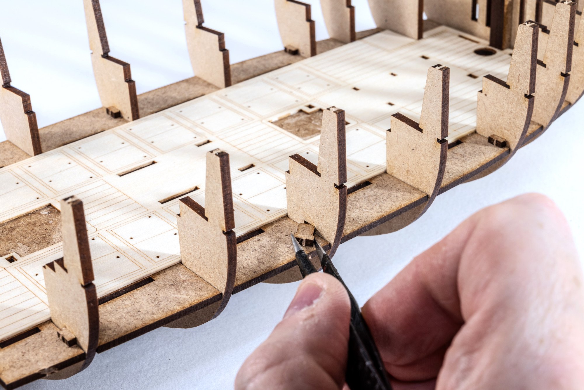
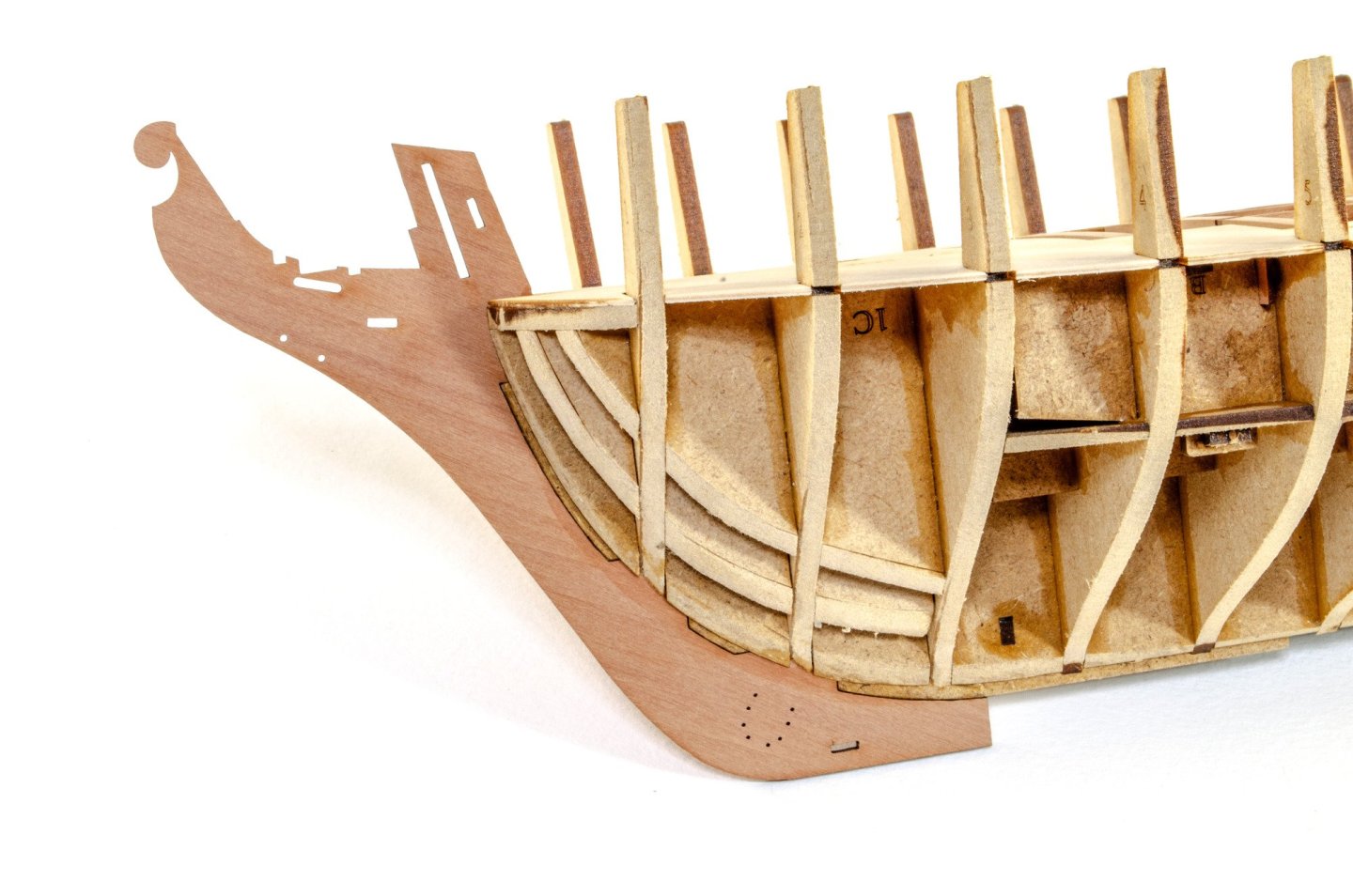
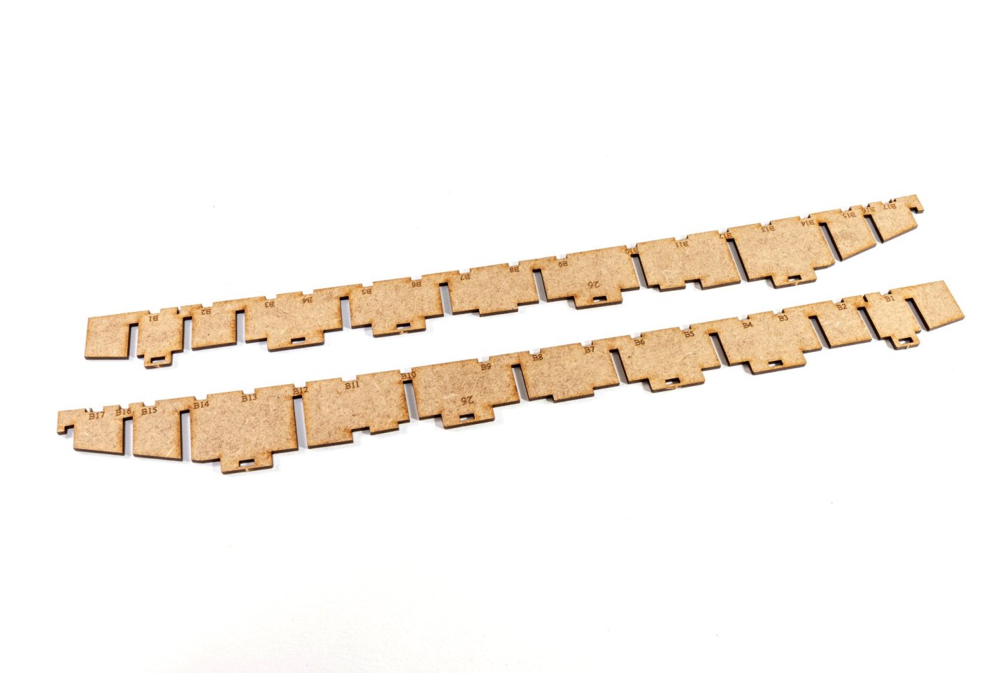
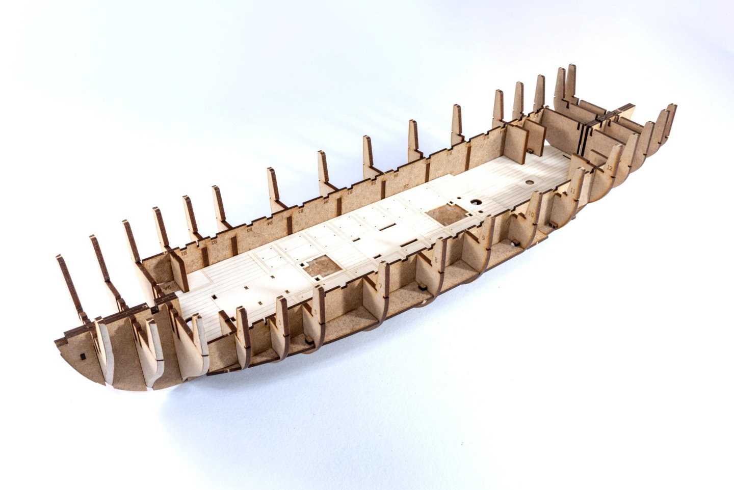
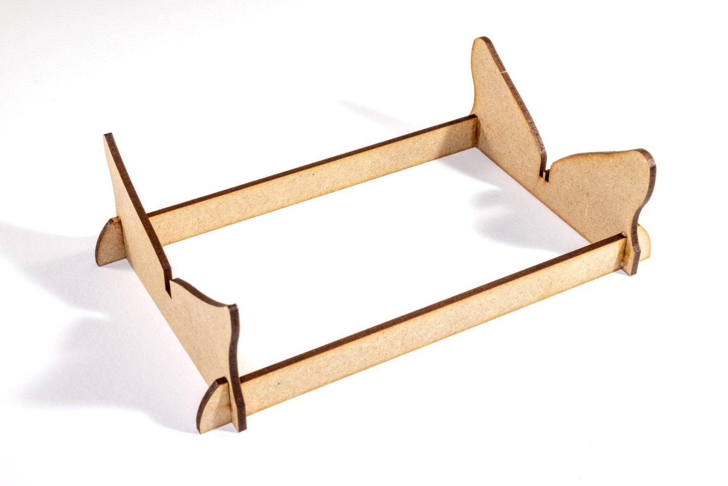
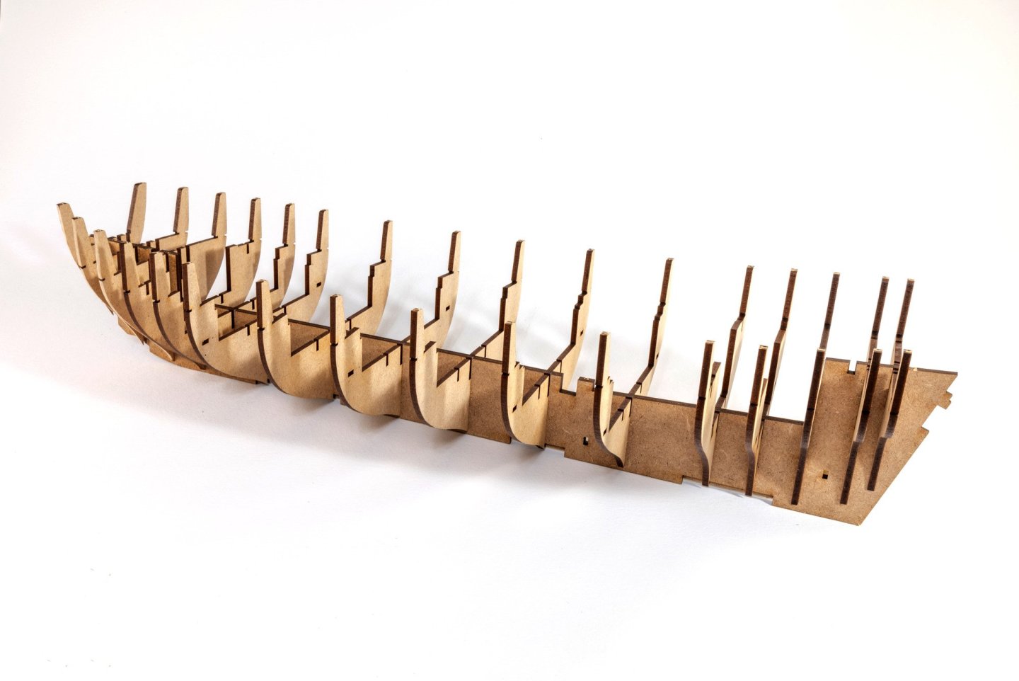
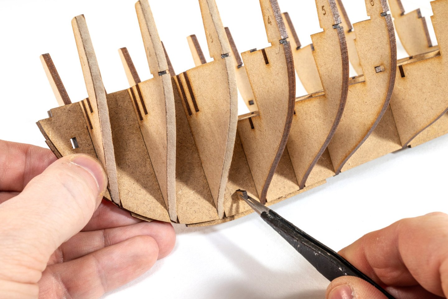
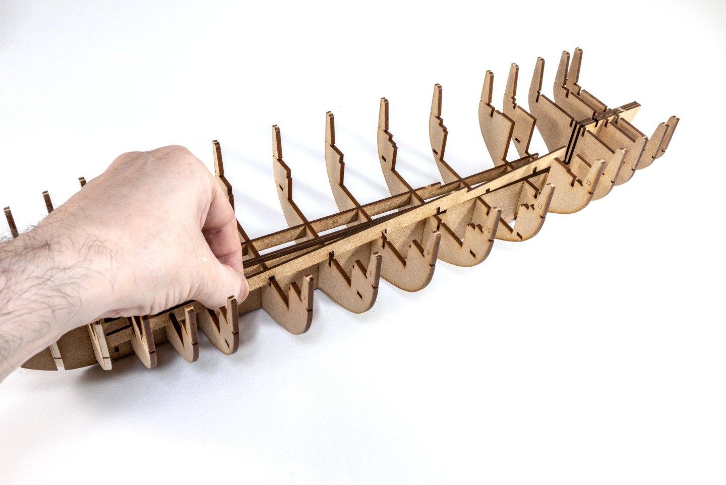
Time for an update. Work on this started on Wednesday and up to the close of today, the ply main deck is now down. Let's look at the abridged build process! As always, the first task is to build up the cradle. Nothing complicated here. The first three bulkheads are engraved to provide a rough gauge for bevelling. As Indy is still in my room, I decided to use sanding sticks to even the parts. Ideally, you should use a rotary tool on medium speed. All bulkheads are now fitted, except for the last one, #17. To lock the bulkheads into place, doublers are slotted either side of the bulkheads, and then locked into place with pegs. This also strengthens the keel, whilst allowing a very slight wiggle to the bulkheads. NO GLUE IS APPLIED anywhere until later. To provide additional deck support and further solidify bulkhead positions, longitudinal strips are now slotted across the top of all bulkheads. The MDF sub-deck is fitted with an engraved deck section representing the lower deck. This is then sat in place and MDF pins used to secure this in place.


- 76 replies
-
- 19
-
-
- Harpy
- Vanguard Models
- (and 1 more)
-
You've done such a lovely job of this. I definitely this is your best work yet, and I look forward to seeing Adder.
- 587 replies
-
- 5
-
-
-
- Indefatigable
- Vanguard Models
- (and 1 more)
-
Mine was sanded, filled, cut back, filled, sanded about 3 or 4 times. I think it's a rare occasion when you get it first time. Yours is looking real good though.
- 422 replies
-
- 5
-
-
- Vanguard Models
- Sphinx
- (and 1 more)
-
They really do look great. Hope to see more iterations soon.
-
Oh, there's a roll of 6mm copper tape included for the coppering. IMHO, this stuff is very satisfying to apply, as well as quick and easy.
- 76 replies
-
- 8
-
-
- Harpy
- Vanguard Models
- (and 1 more)
-
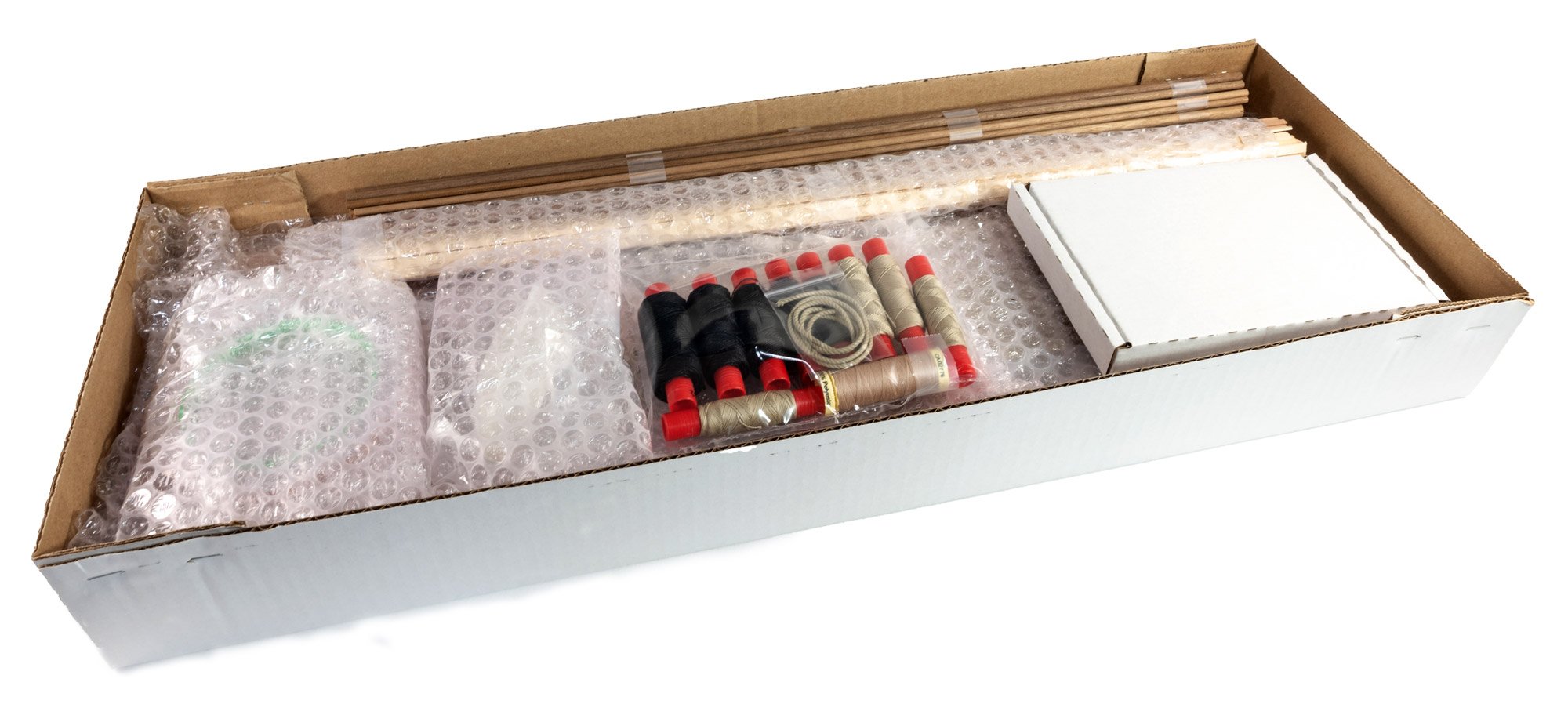
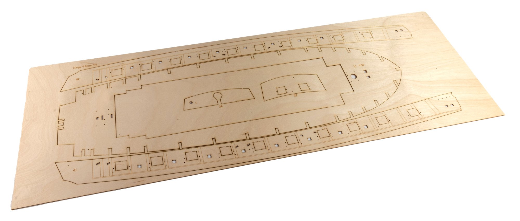
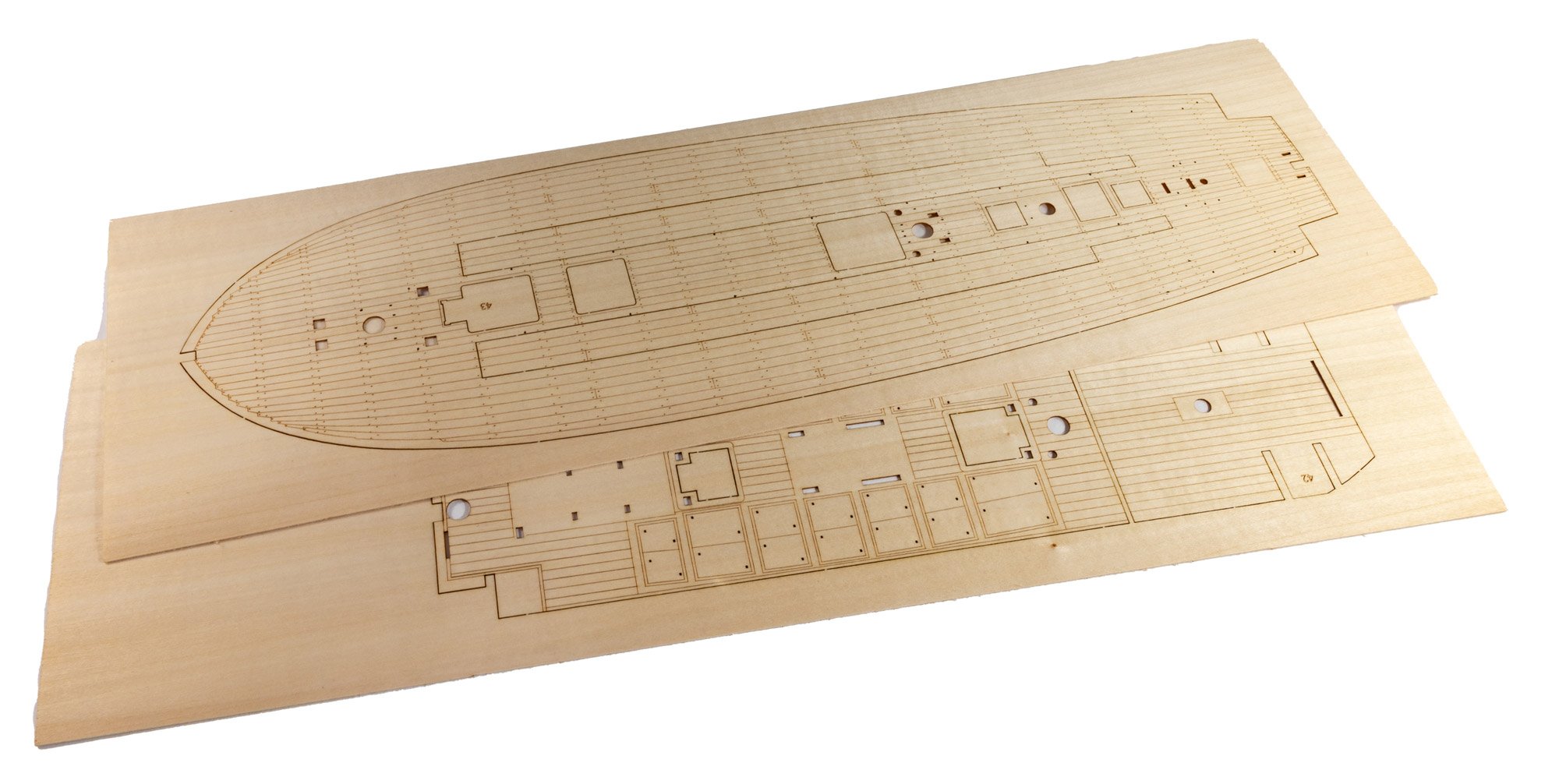
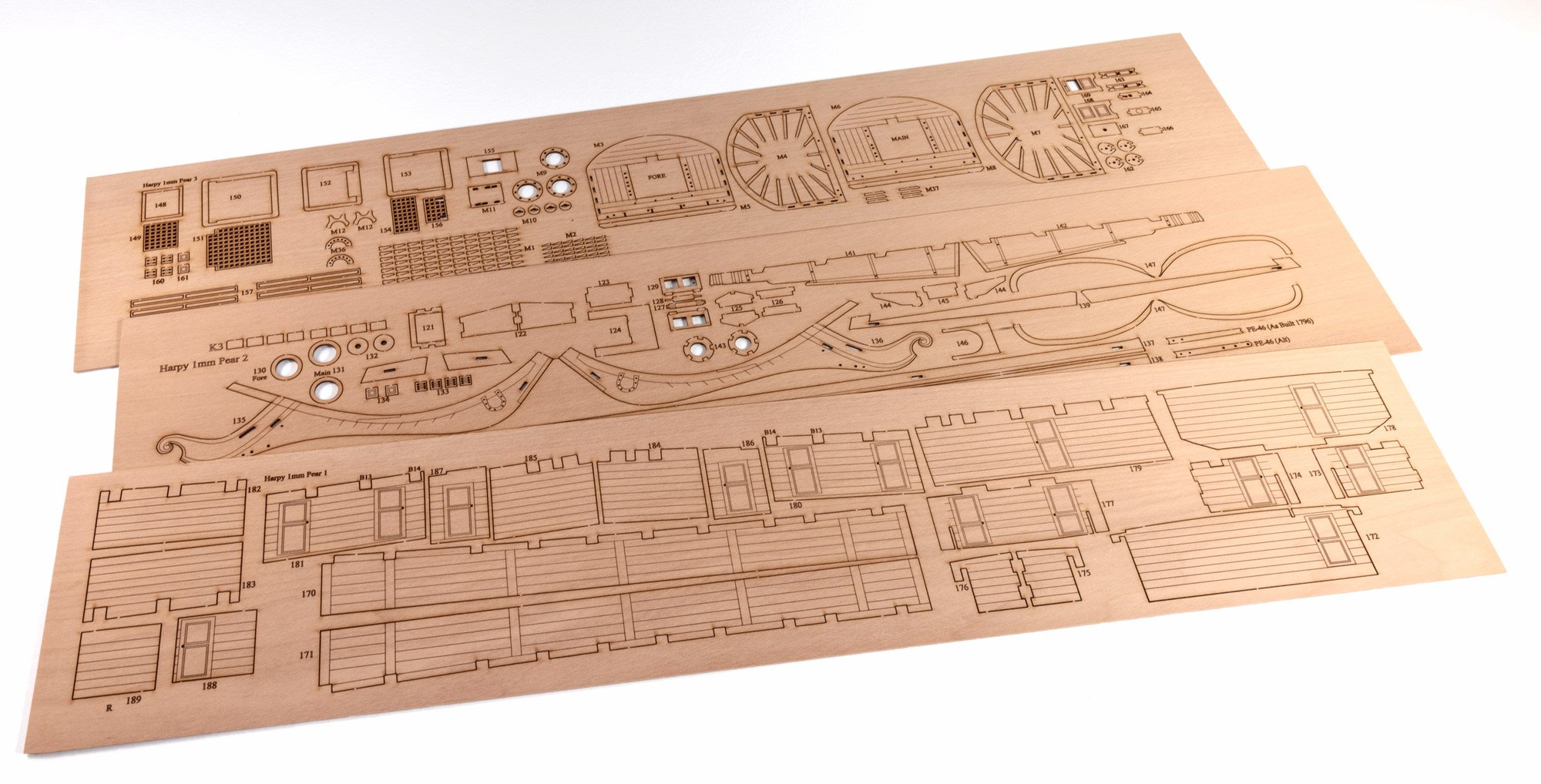
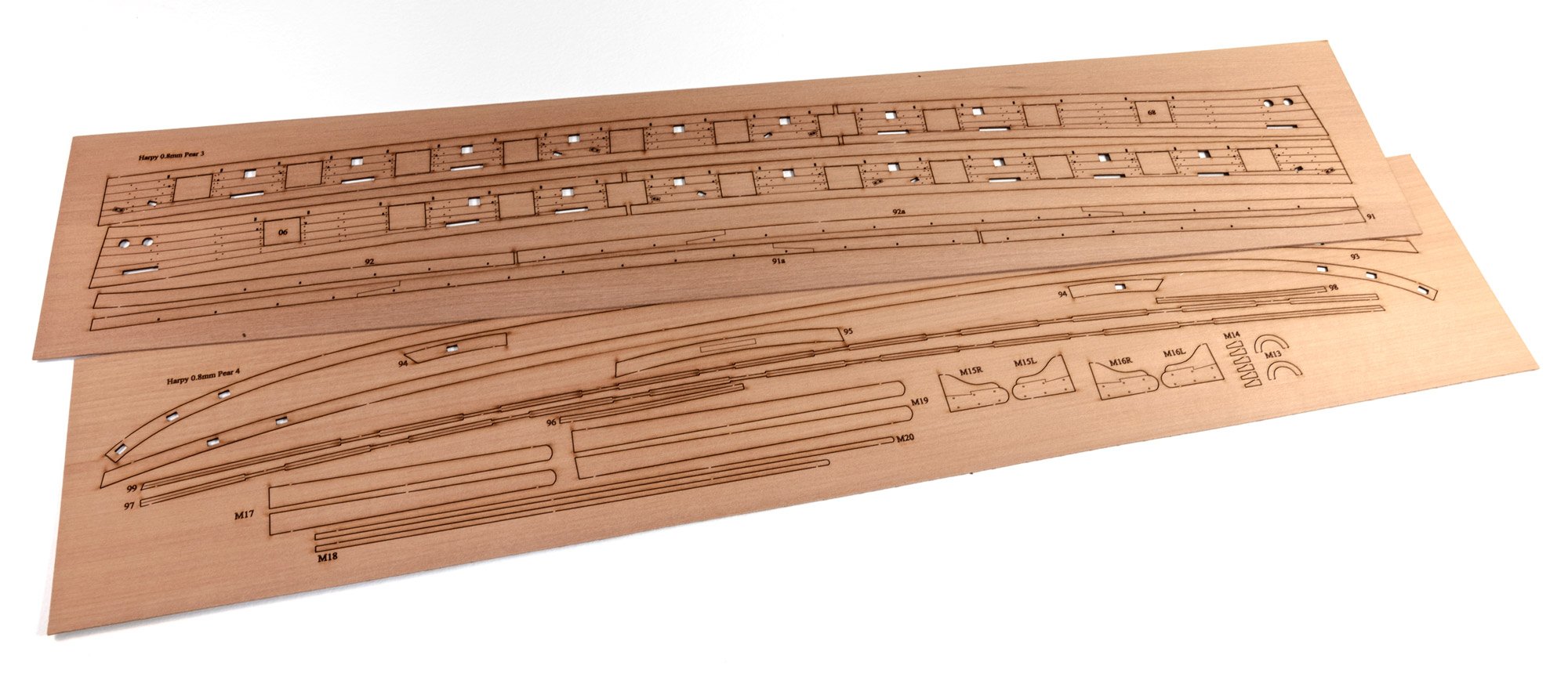
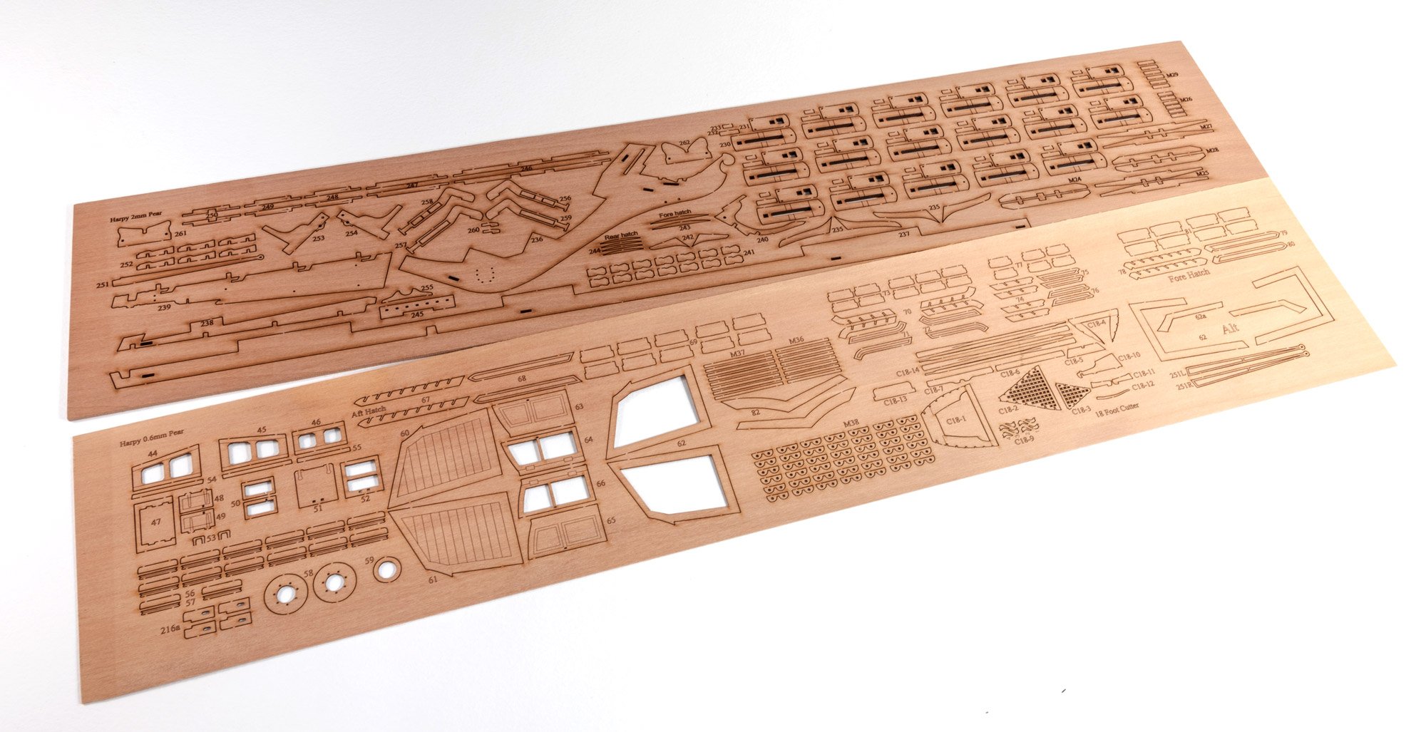
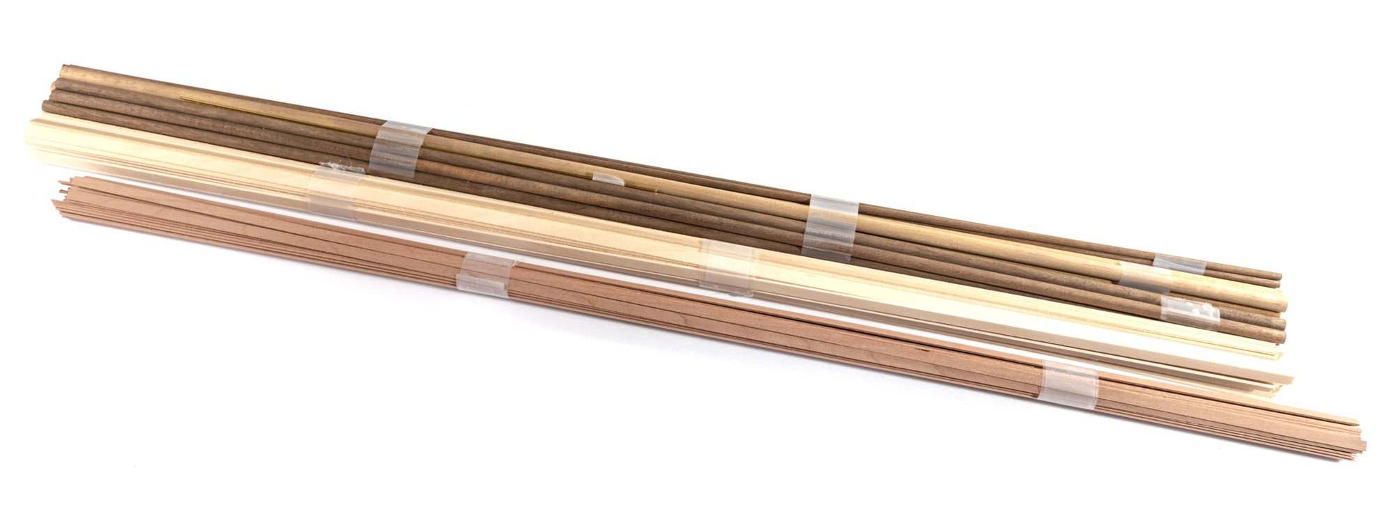
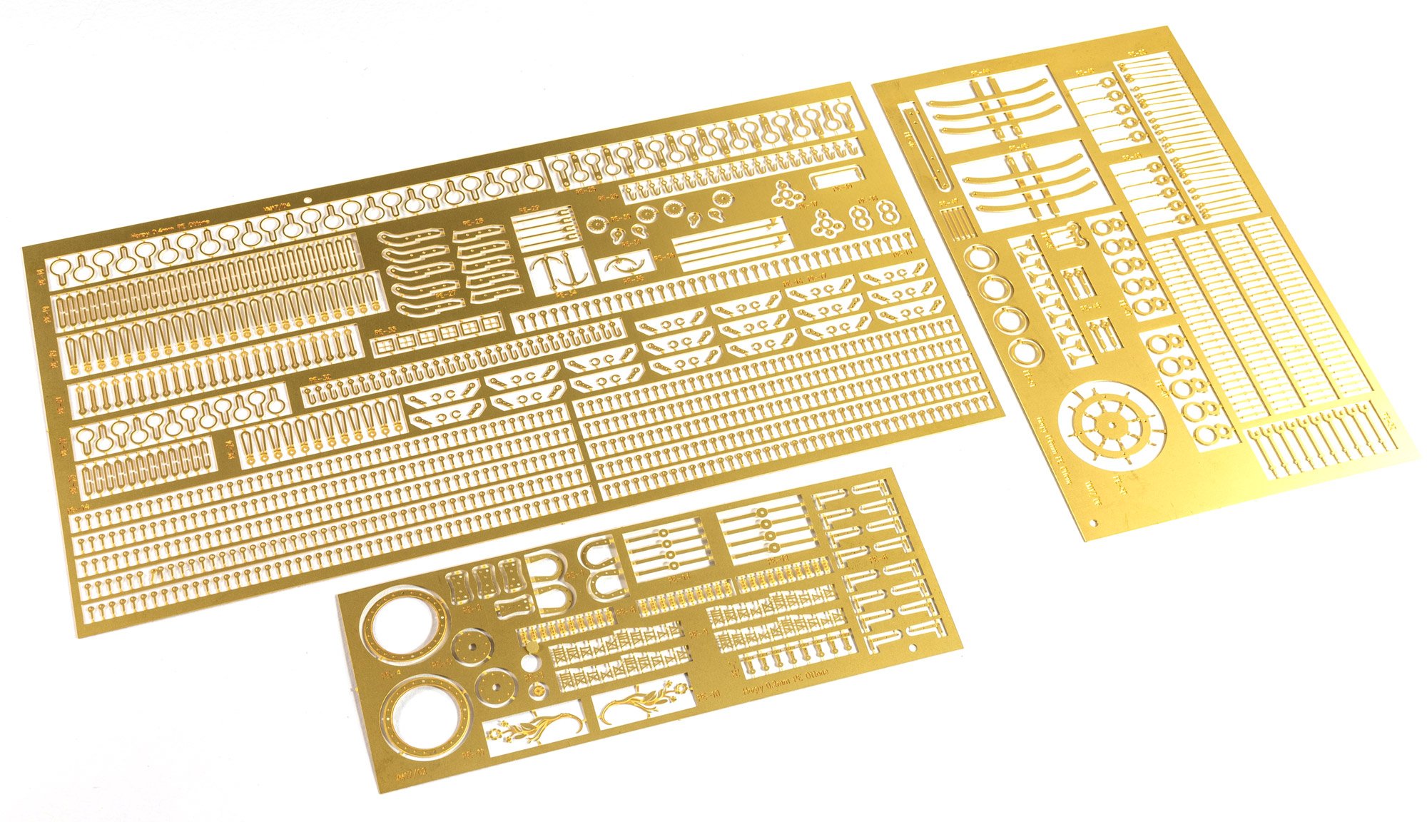
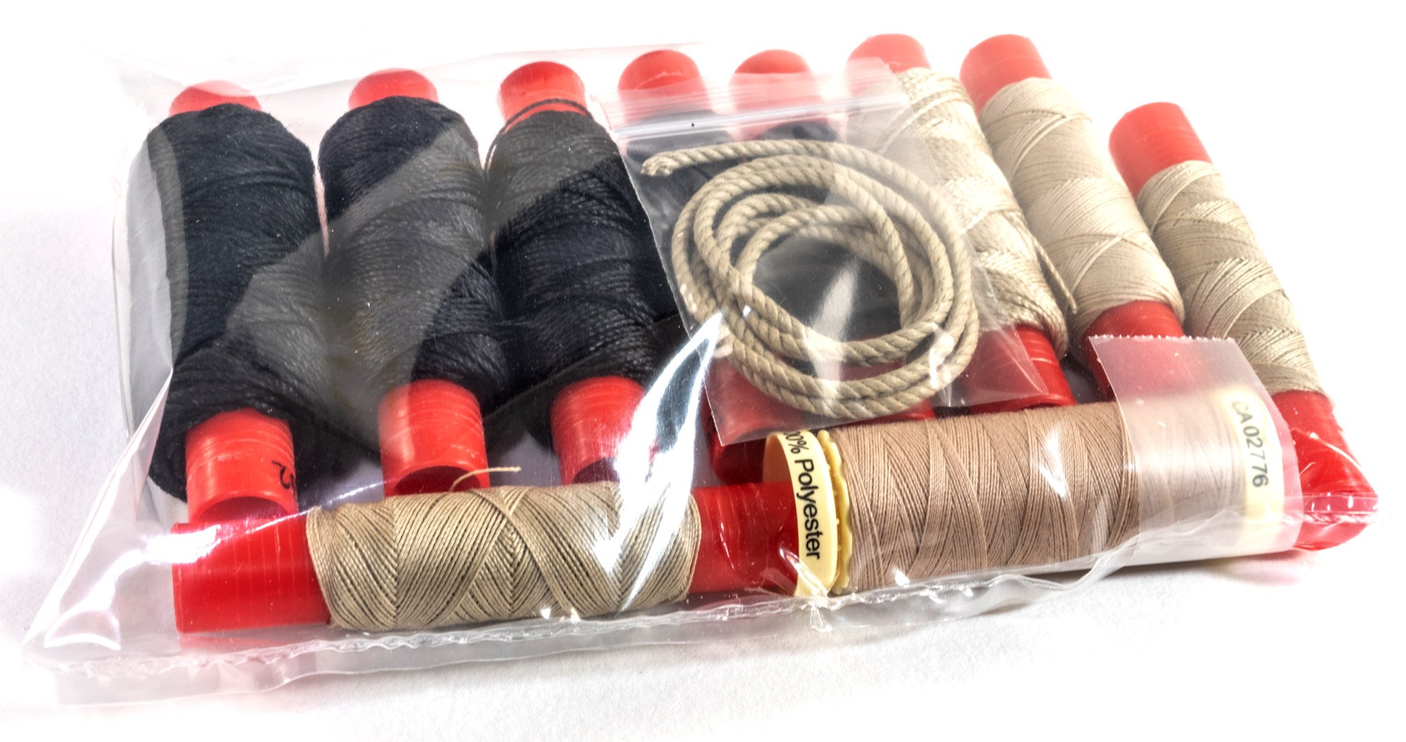
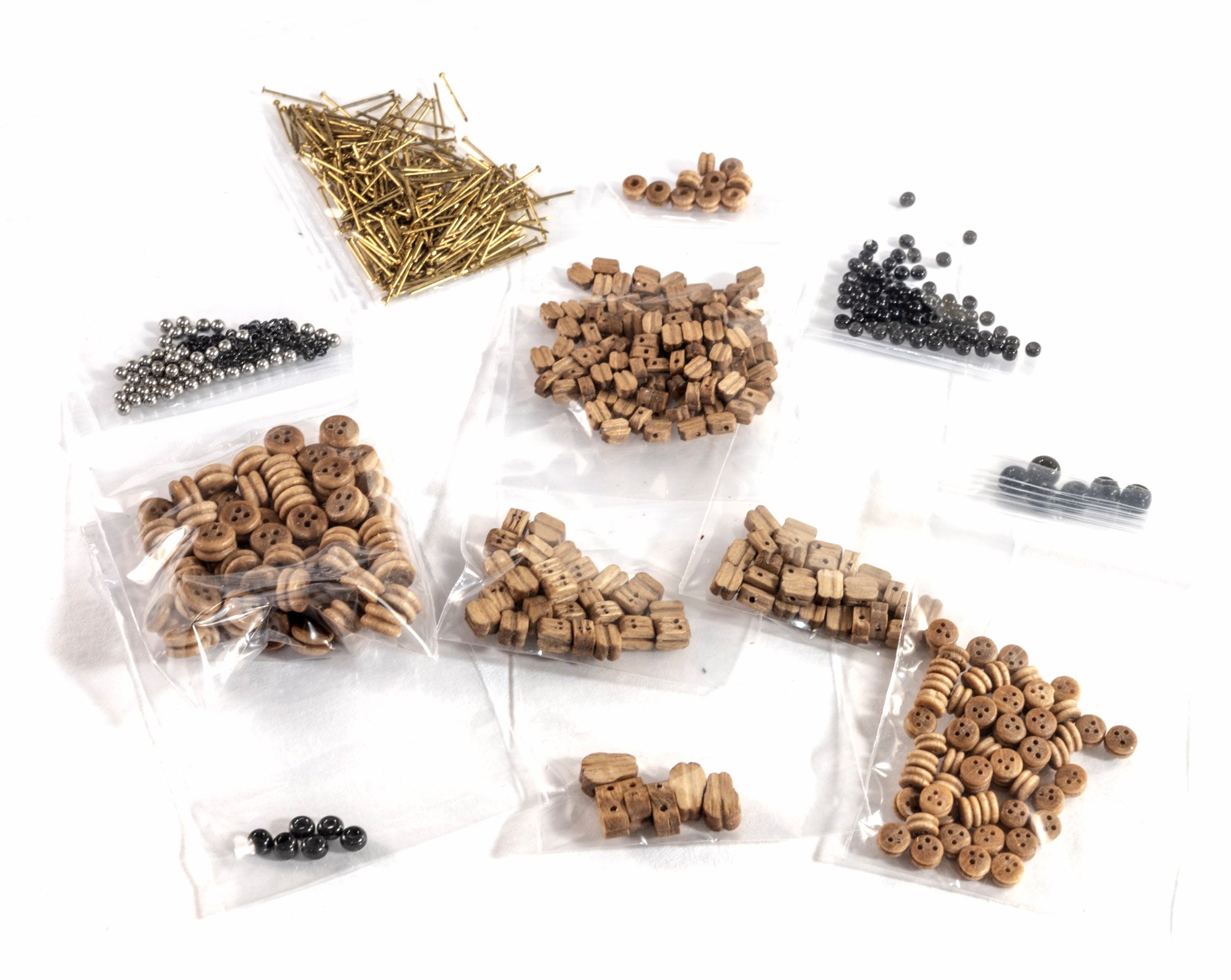
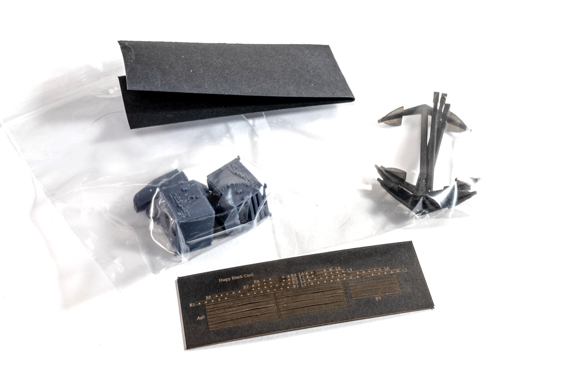
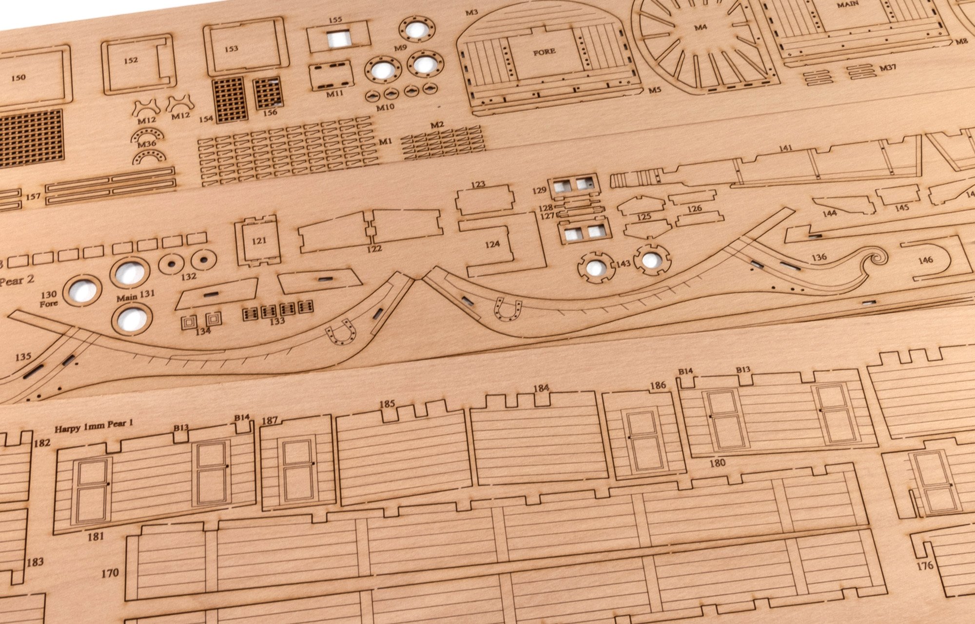
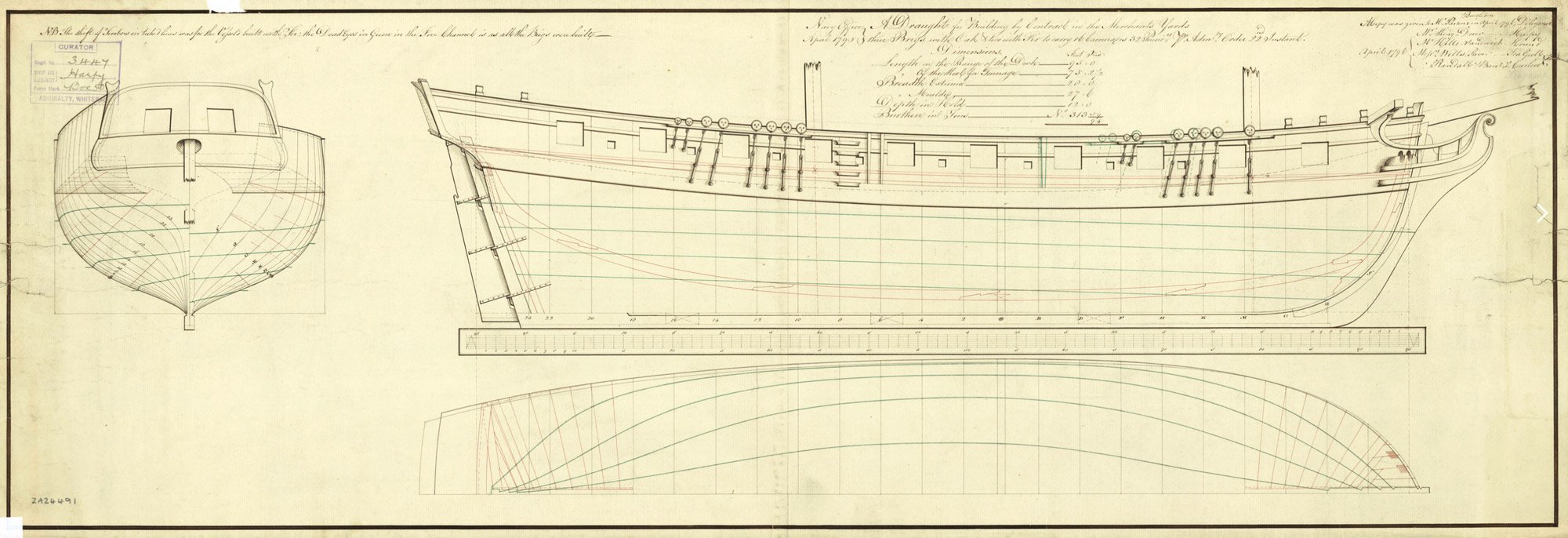
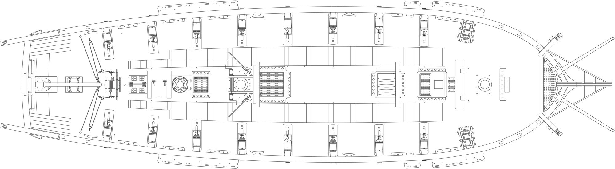
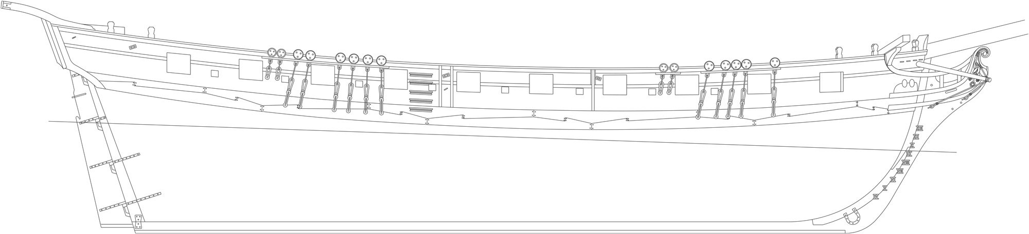
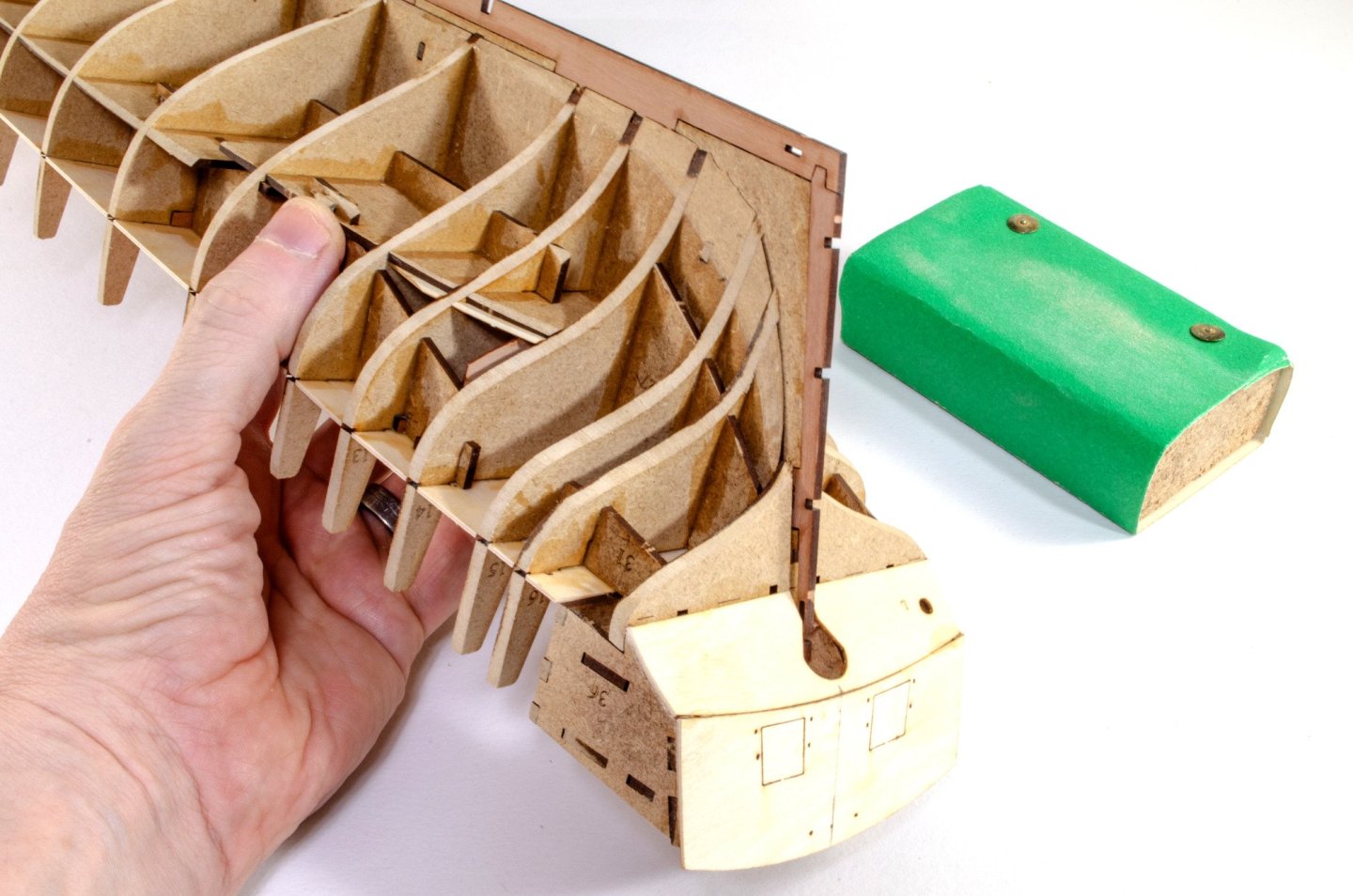
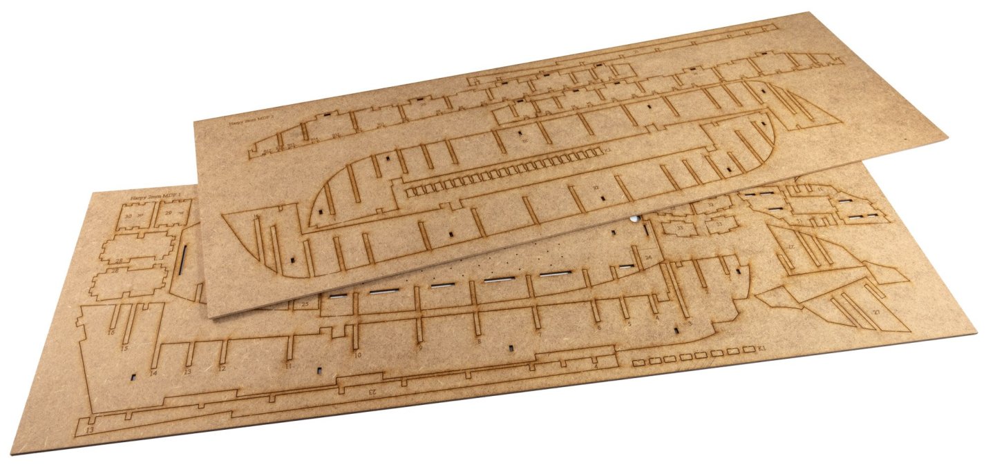
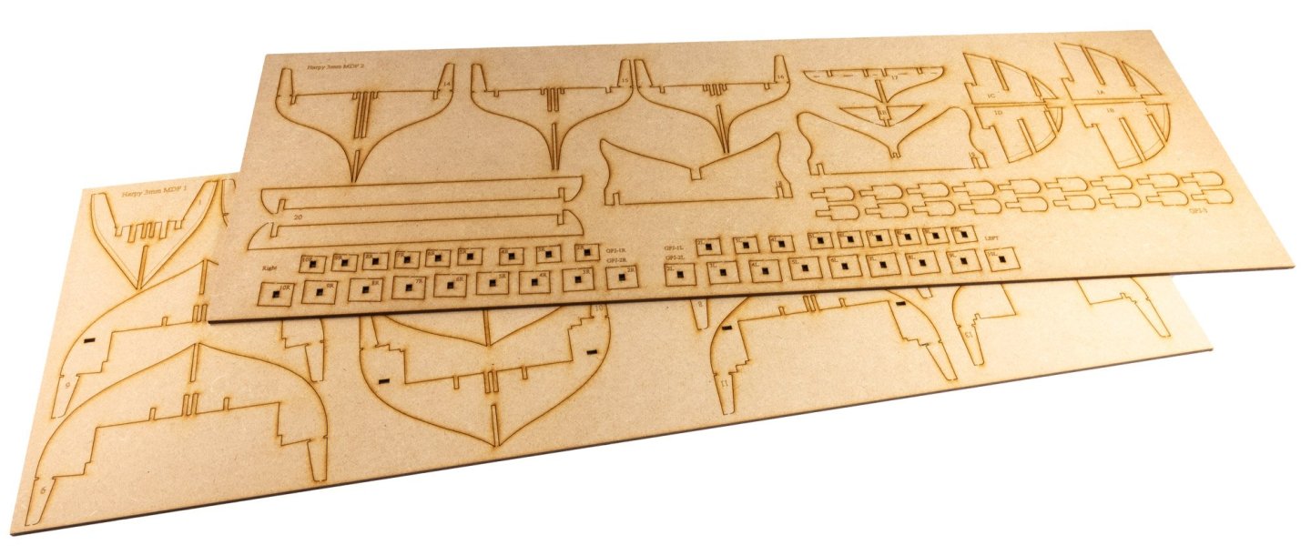
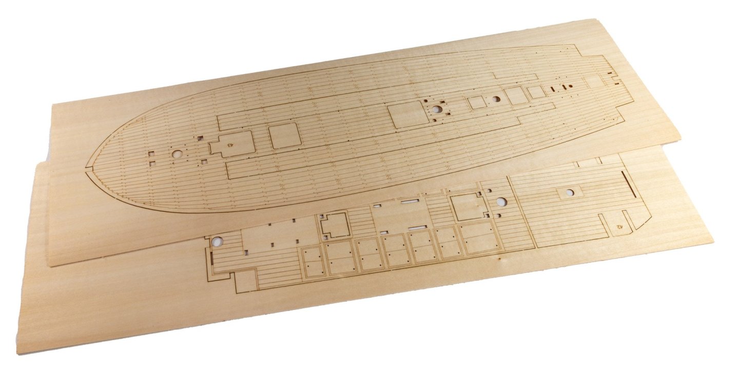
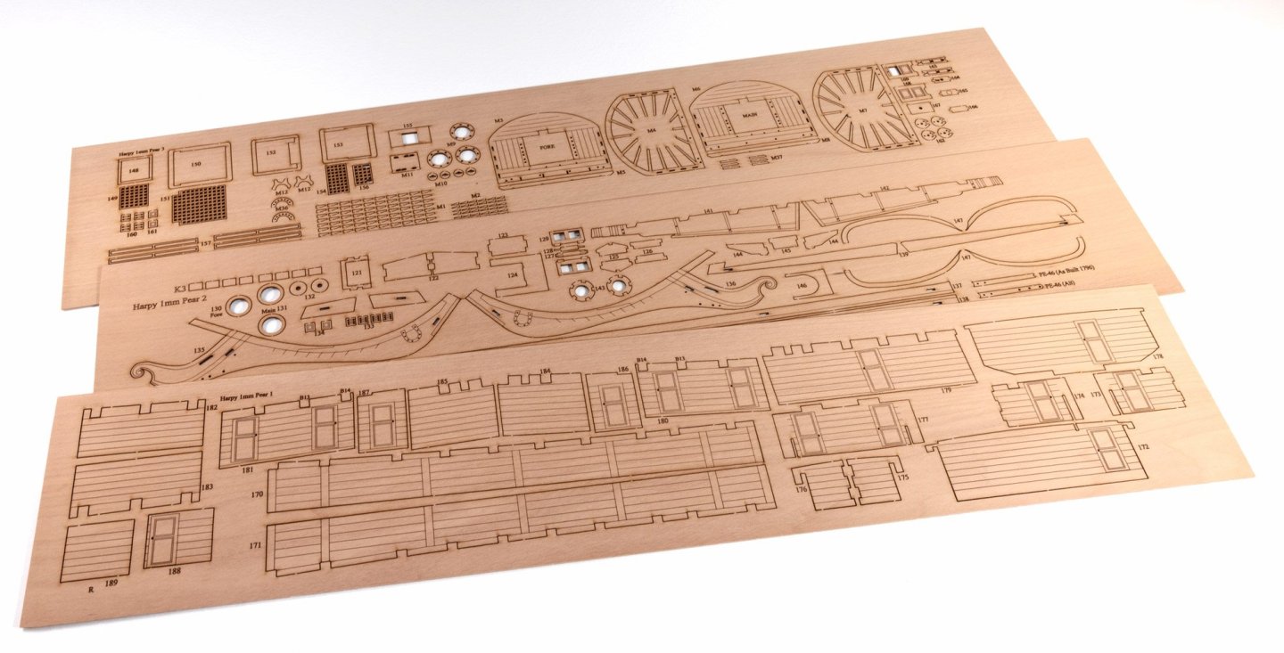
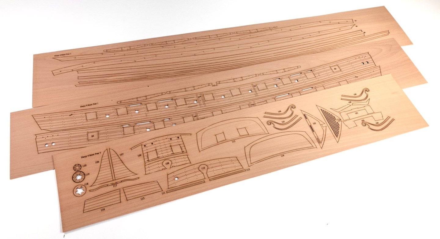
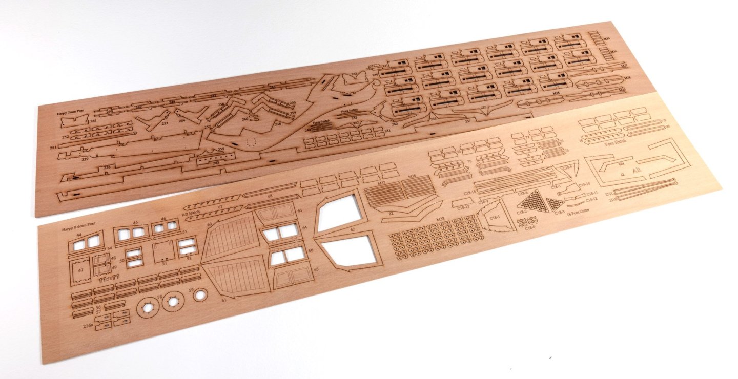
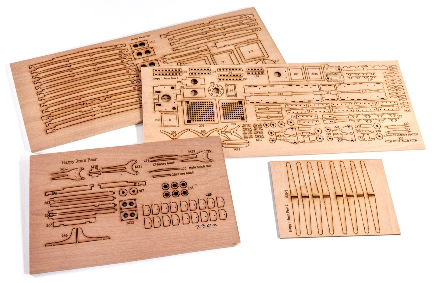
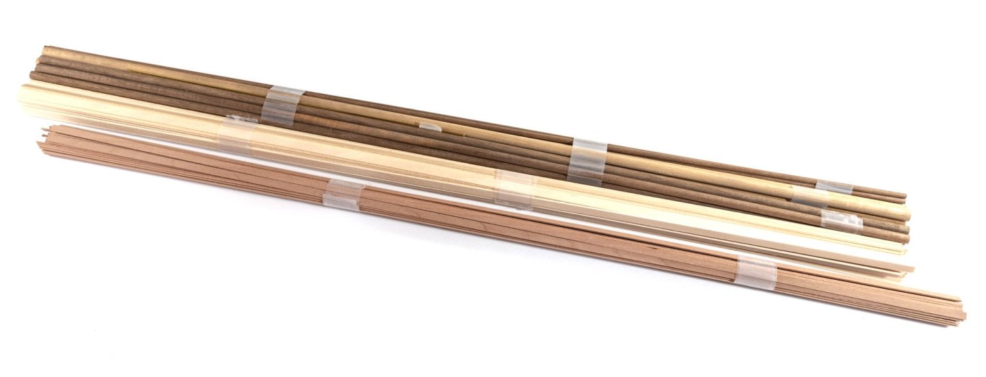
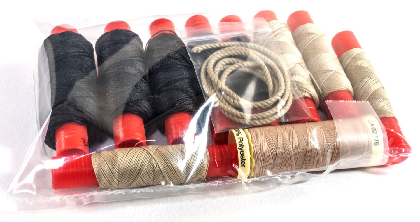
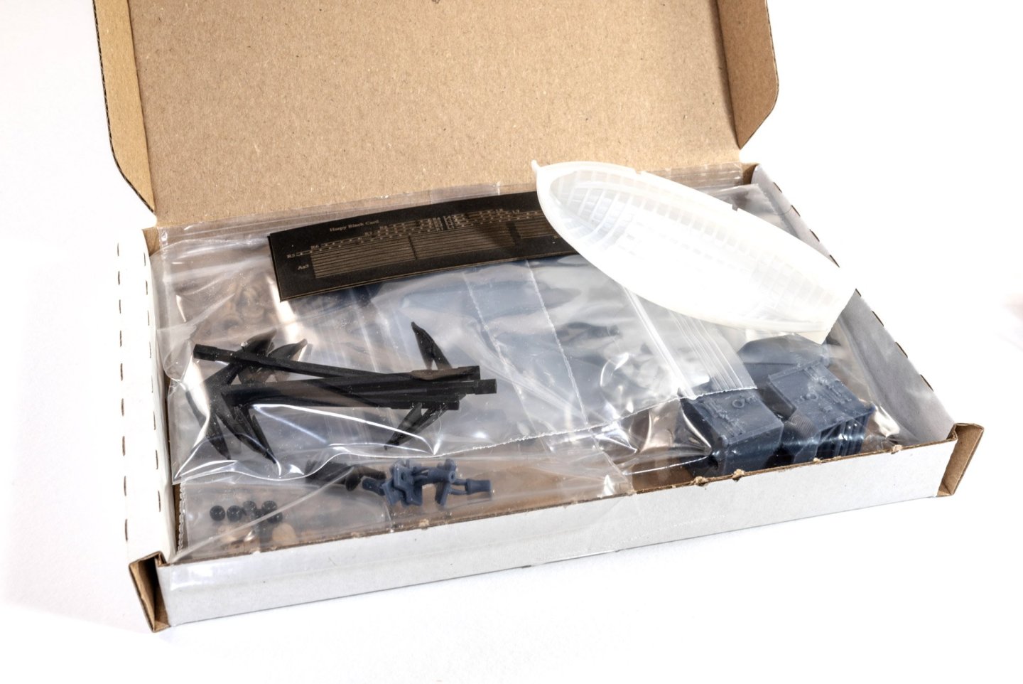
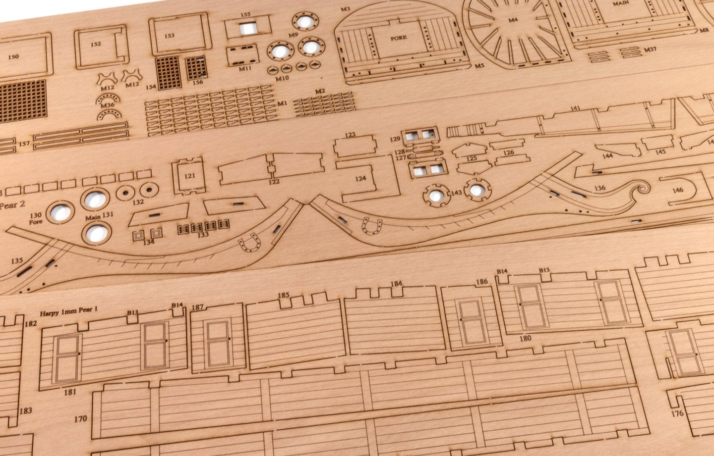
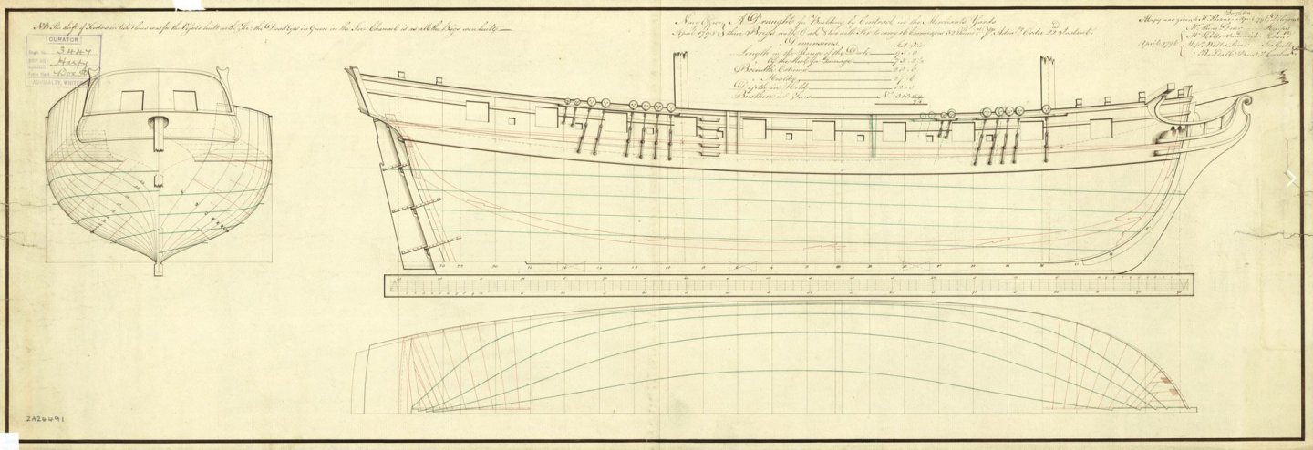
HMS Harpy - 1796 HMS Harpy was a Royal Navy Diligence-class brig-sloop, launched in 1796 and sold in 1817. She was the longest lived vessel of her class, and the most widely travelled. She served in both the battle of Copenhagen and the British invasion of Java, took part in several actions, one of which won for her crew a clasp to the Naval General Service Medal, and captured numerous privateers. The Navy sold her in 1817. (from Wikipedia) Prototype It seems like an age since there was something new on my bench for building. HMS Indefatigable's construction was slightly punctuated by Grecian, but as now I'm idle again and in need of doing something useful with my time, Chris sent over his latest, HMS Harpy, for me to build up and create the material for the manual! Chris shipped this out in a typical Grecian/Adder size box and there's quite some weight in this one, even without the plans and eventual manual. The box already seems packed out, and as usual, Chris's boss, Chan, has properly packed everything so nothing was broken. There are FOUR sheets of MDF in this kit (two x 2mm and two x 3mm), for creating the hull framing and the construction cradle. Again, the hull is designed so you can more or less build it dry, align and tweak as necessary, and then apply your glue to a now perfect hull. One sheet of 0.8mm ply is supplied for the main deck that sits under the engraved deck. Here you'll find the stern transom and counter, and the inner sandwich for the bulwarks. Here are the engraved lime decks.The main deck has optional parts to fit into the cutouts...should you feel the need to add them, and another engraved deck sits on the MDF sub deck, creating the ship's lower deck. The whole lower deck area will be festooned in engraved details too. This should look quite special. The upper deck beams are authentically placed and the lower ply support deck won't be seen at all on this build. Three 1mm pear sheets are included. These contain parts for the mast tops, keel/prow/rudder sheathings, and at the bottom you'll see all those engraved walls for the lower deck area. There's also a cabin or two included in that mix. Also note the engravings on this kit are enhanced too. Three sheets of 0.8mm pear contain the wales, anchor stock facings, outer bulwarks and various stern, bow pieces etc. Two more 0.8mm sheets contain the inner bulwarks, gunwales and parts for the mass, such as the fish etc. The upper sheet here is a 2mm one, containing the actual keel, prow and rudder post, rudder, carronade trucks, bitts, catheads, trestle tree parts and cutter mounting frames. The lower 0.6mm sheet concerns itself with numerous details for deck furnishings, stairways and parts for finishing the cutter. The cutter itself will be supplied as a beautiful and accurate 3D-printed part, so no more having to plank small boats for this one. You will have options for mounting the cutter....either use the deck mount parts, or hang over the stern on davits. Two 1.5mm sheets are included, containing anchor stock parts, as well as channels, cleats, cannon carts, grates, shot garlands, and various parts from bow to stern. A single 3mm sheet has parts for a small number of deck beams, gaff and boom ends, chimney and main hatch frames etc. Lastly, the 4mm sheet contains the main deck beams, coamings, mast caps. Lime planking is used for the first layer, as is normal, and pear will be used for the second layer. You also see dowel here for masting and a quantity of brass rod is also supplied. Three photo etch sheets will be supplied with this release. You'll recognise many parts here, from eyelets, decor, ship's wheel, strops, trestles etc. And here is the rig pack! I'm still firmly in rig mode from Indy, and the anaesthetic hasn't yet worn off! A box of fittings holds the anchors, blocks, ship's stove, laserbak rudder hinges, cannon and carronades/carronade wheels, parrel beads, thimbles, brass pins, cannon shot, and black cartridge paper. I'll make a start on Harpy tomorrow eve, but there'll be no sanding until Indy has gone. She's still sat on my bench and I don't want to get that dusty!


- 76 replies
-
- 34
-
-
-
- Harpy
- Vanguard Models
- (and 1 more)
-
Only a Yorkshireman would say 'carping' 😆
-
Welcome to our little forum, @OcCre A pleasure to see you here.