


thibaultron
-
Posts
2,944 -
Joined
-
Last visited
Content Type
Profiles
Forums
Gallery
Events
Everything posted by thibaultron
-
 Chuck. I was thinking about your counting of the collars problem. Maybe leave the proper number, still on the base sheet, and supports, and let the modeler separate them?
 -
3D Naval Guns 1850s ~ 1870s
thibaultron replied to JerryTodd's topic in CAD and 3D Modelling/Drafting Plans with Software
This is a picture of the USS Thomas Freeborn labeled as taken in 1861. I think this shows a gray, or faded black carriage. as the barrel is also gray.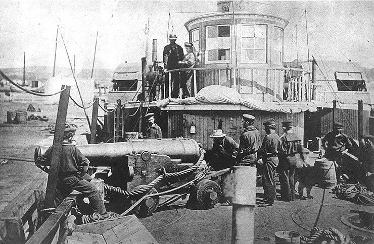
-
Hobby Laser Machine
thibaultron replied to kgstakes's topic in Modeling tools and Workshop Equipment
For CNC machining , as far as software, you will need at least windows 10, for compatibility with the other software. UGS software (free) is used to drive the CNC router directly from your computer, with newer CNC machines, via an USB cable. Some of the newest machine can use a thumb drive directly, to cut the file. To create the cutting files you need a "Creator" program to generate the cut files. The general ones are Easel (a very basic program, with limited 3D object usefulness). It requires an on going subscription. Carbide Create, better but not full 3D object machining and limited 3D model creation) also a subscription based program, with a high monthly fee. VCarve, Desktop ~$350 to purchase, no monthly subscription. For modeling you will still need to use some type of 3D CAD program to create the original scale model. The typical two used are both subscription based SketchUp and Fusion 360. I have not tried it but Blender is supposed to also be able to create 3D files that you can use to send the the CNC programs previously mentioned, and it is free! Others will have to chime in on the Blender option. -
The Mossy Shipyard by Bryan Woods - 1:1
thibaultron replied to Bryan Woods's topic in Non-ship/categorised builds
Would putting screens in the windows help reduce the bird impacts? Any opinions? -
Hobby Laser Machine
thibaultron replied to kgstakes's topic in Modeling tools and Workshop Equipment
For really small detailing, you might want to check out the 3030-PROVer MAX CNC Router Machine with Linear Guide & Ball Screw Motion, Achieve ±0.05mm Accuracy for High Precision Metal Aluminum Copper Acrylic Engraving, Supports 4th Axis Rotary Kit It has ballscrews for the axis feedscrews. The stated accuracy is + .05mm or 0.002 inches. -
Drop them in in ones and twos, so they don't jam. Pharmiststs tray to funnel.
-
You can buy decal sheets that you run through a printer to create your own.
-
Most of the plans from Chappelle's books are available from the Smithsonian, for a suitable fee.
-
A few years ago Clayton A. Feldman (a former Editor of Ships In Scale) wrote a practicum on building the Lexington, using new research, to generate a new set of plans for her. While I'm sure that his practicum uses either POF or POB for the hull construction, you could use Davis's solid hull methods for the hull. Back when Davis wrote his book, less was available to draw plans from. I suggest you at least look at the practicum, for the plans. It available from the NRG store. Building the Continental Navy Brig Lexington, A Practicum by Clayton A. Feldman. They also have another of his practicums, that covers three models of increasing complexity, to help get a new modeler started. This is also available from the NRG. Progressive Scratch Building in Ship Modeling by Clayton A. Feldman. I have the later, bought when Ships In Scale was still in publication, and found it quite helpful, in understanding ship modeling.
-
3D Printing Cannons in Resin
thibaultron replied to thibaultron's topic in 3D-Printing and Laser-Cutting.
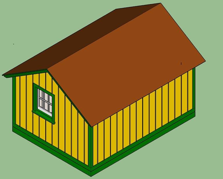
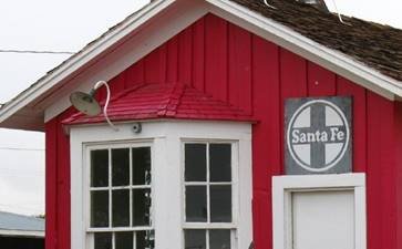
The museum I contacted, came through with 2 additional archived photos the Oil Junction Depot, that helped me determine more details of the building. I also found a photo on the Web showing the door. The windows were double hung single pane ones, not the 6 panes I thought. The sign was also about 10" shorter than my guess from the corner shot I had. It took about half a day to find a true type font that was close to the one the Southern Pacific used for the depot signs. It is call the "Consolidation" font. The real railroads used their own drawn fonts, not any "Standard" ones created for our computers. Here is a picture of the "Final" version. The lettering on the sign is 3D, not just flat painted ones. I also have the sign without the lettering, should I decide to try making decals for the lettering. The 3D letters are only a scale 1/4 inch thick, so in HO scale they would be the same thickness a a sheet of paper. Here is a picture of the old model. Here is the final version, without the sign lettering, showing the new door and screen door . Note, that the picture that showed the door also showed that the sashes (under the OSB used to board them up) were brown, so that was also changed from the white I used before. And here it is with the sign lettering added. I've been working on the Commonwealth cannons also. I now have 7 of the twelve size barrels, I have drawings for completed. When I'm done there will be three versions of the cannons. The first will be with the original cypher when they were cast under the "Rebel" rule, the plain barrels used when Charles retook his throne, and had those cyphers ground off, and the version that were cast later with his crest. Then I have some sizes that a member asked for that were specific to drawings he found for HMS Tiger. I'm going to concentrated more on the cannon, now that I finished this depot.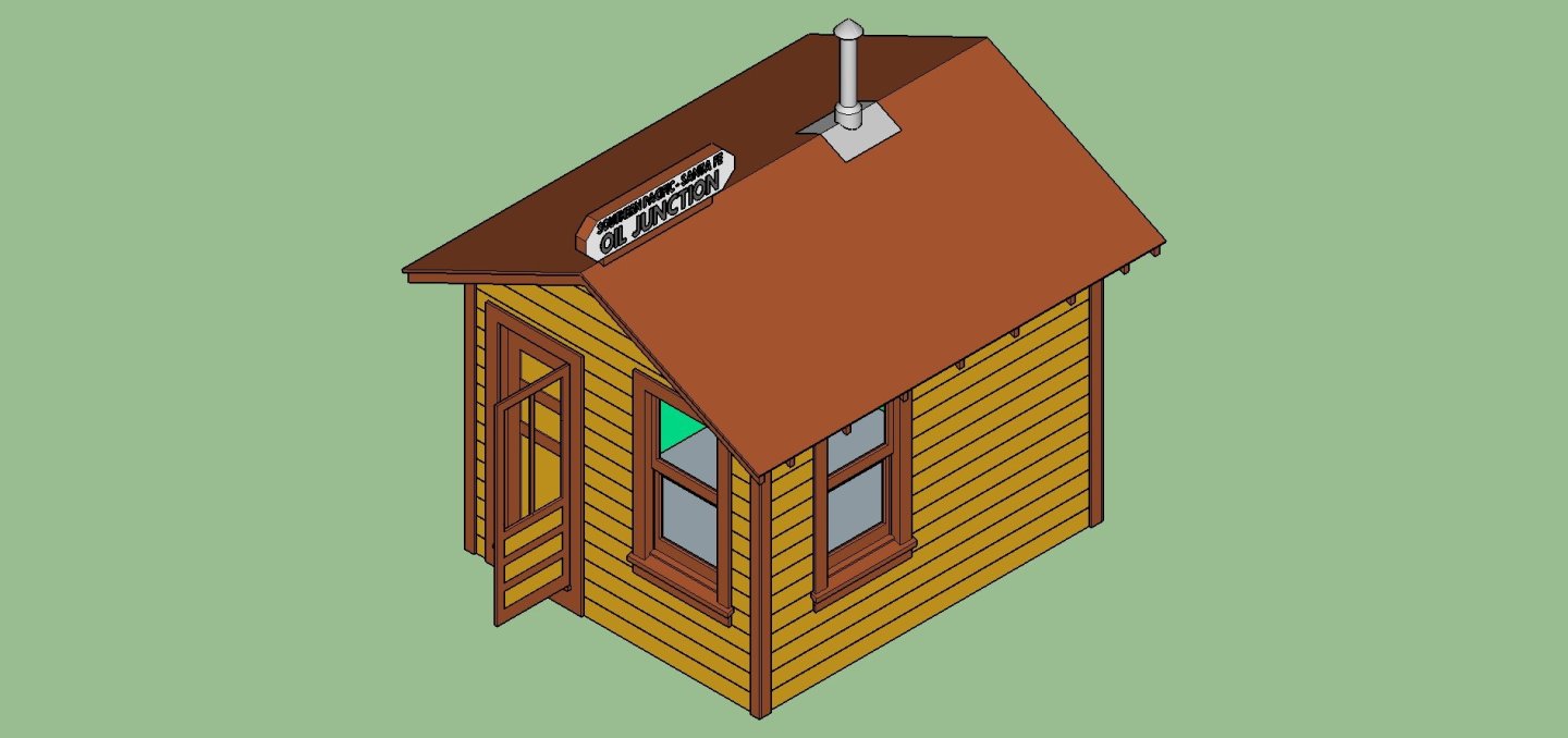
-
3D Printing Cannons in Resin
thibaultron replied to thibaultron's topic in 3D-Printing and Laser-Cutting.
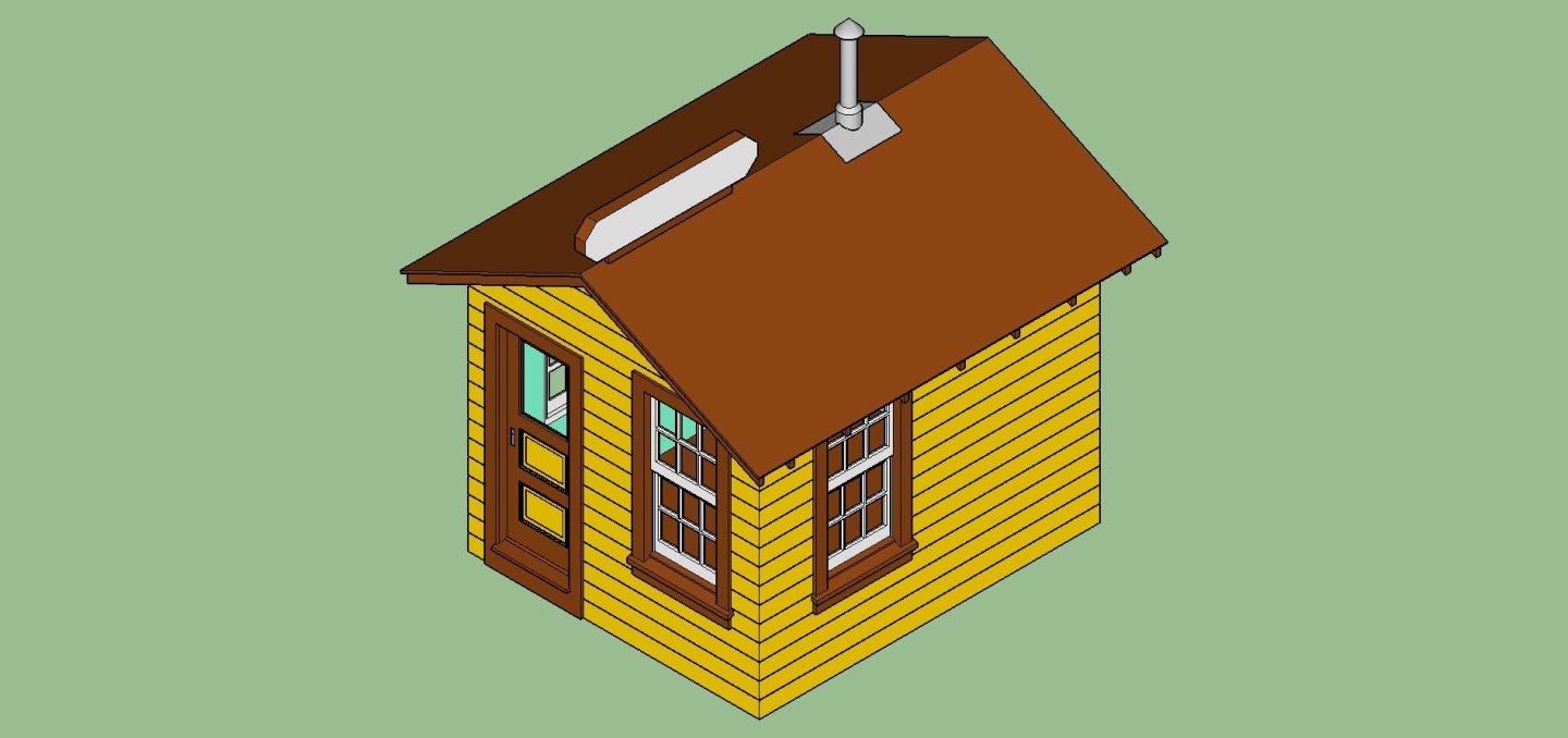
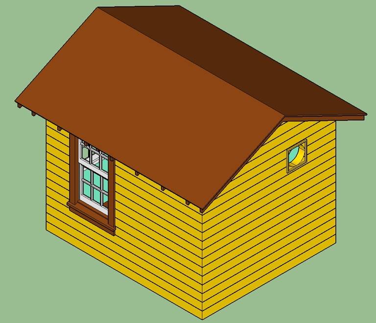
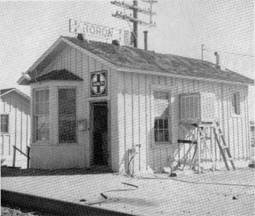
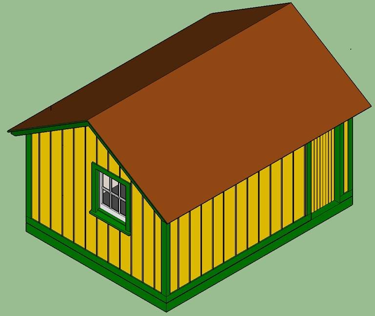
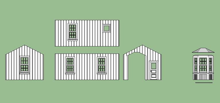
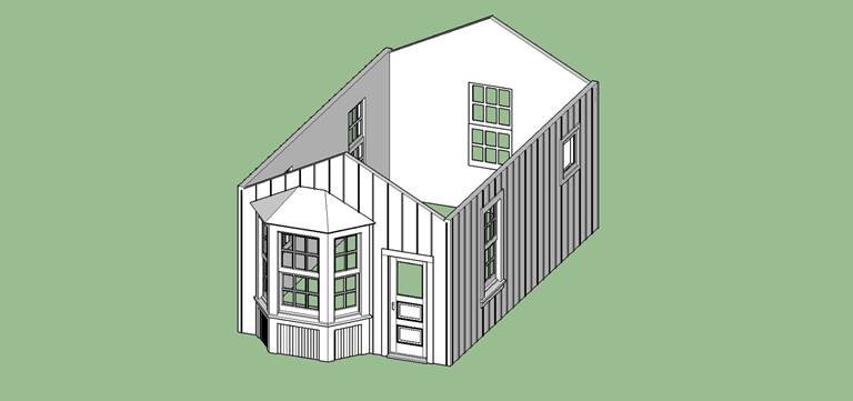
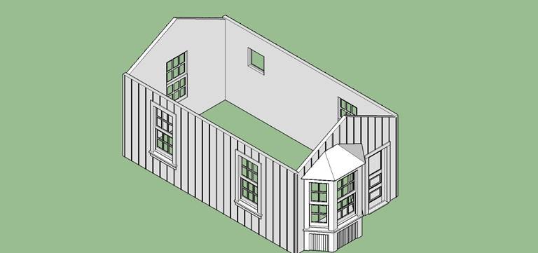
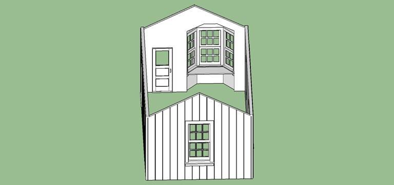
While I’m CADing the British Commonwealth cannons, I’m continuing with drafting some small Santa Fe Railroad depots. I do a day of cannons, then a day of depots. I’m CADing small stations for the eventual display I’m making to show a variety of SF depot designs. I have models of several of the standard depots. Most of these are larger standard types, so a few small unique ones will help to save some space, and be different from the more common kit models I have. This latest depot, is the Oil Junction Depot. This is a small depot that served a junction of the Santa Fe and the Southern Pacific in California. The depot was built to SP standards, by the looks of the drawings and photos. While this building still exists in a museum, the information on it is scarce. All I have is three photos, and the drawings from an article in a SF Historical Society magazine. A small photo in the magazine, and another I found on the Web, are fairly low quality, making details hard to see. The biggest problem, is that the depot had screens on the windows, and door, completely masking the window and door details. I contacted the museum, to see if they had any information on the building on their site. They helpfully told me that all they could help me with was pointing me to a small photo hidden on Web site. Once again, the screens hide the details. They were unwilling to actually walk out and just give me a short description of the windows and door! The SP depots have similar looking details to the SF, so I used my drawings of the door and windows to use on this depot model. I did find specs for the SP paint scheme, and pictures of still existing depots to “paint” the depot with. The article indicated that the SP colors were used. Here are some graphics of the model. Note, that the hole in the back wall is for a vent that is screened over. Not sure what I’m going to use for screening, I’ll have to research that. The light green interior walls are also SP standard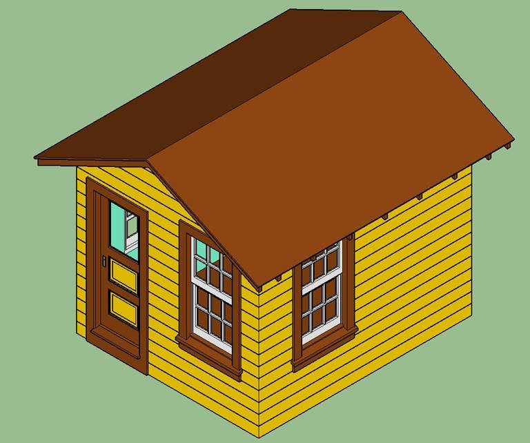

-
3D Printing Cannons in Resin
thibaultron replied to thibaultron's topic in 3D-Printing and Laser-Cutting.
Here is the first of the Commonwealth cannon barrels. This is the 32 Pounder 108 barrel. I'm going to draw all the barrels I have 2D drawings for, initially, with no cyphers. The earlier cannons had the "Arms Of The Commonwealth" cypher on them, then when Charles II retook the throne, these were removed Filed off), leaving no cypher. Cannons cast during his reign had his cypher cast on. I will draw that "Commonwealth" and Charles "Tudor Rose" cypers after I've finished all the barrels. Yes the trunnions are too long. I did this on purpose, after doing a couple of barrels for Chuck, last year. He leaves his long, so that modelers can then trim them to match the carriages they build, which might end up a little wider than a "Perfectly Scale" width. Easy to do for small scale models. When installed the ends can be trimmed to match the model carriage.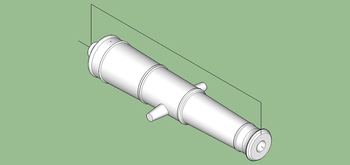
-
Fractal vise on kickstarter
thibaultron replied to DavidG's topic in Modeling tools and Workshop Equipment
Looking at the video, I'd say about 1" round object. -
3D Printing Cannons in Resin
thibaultron replied to thibaultron's topic in 3D-Printing and Laser-Cutting.
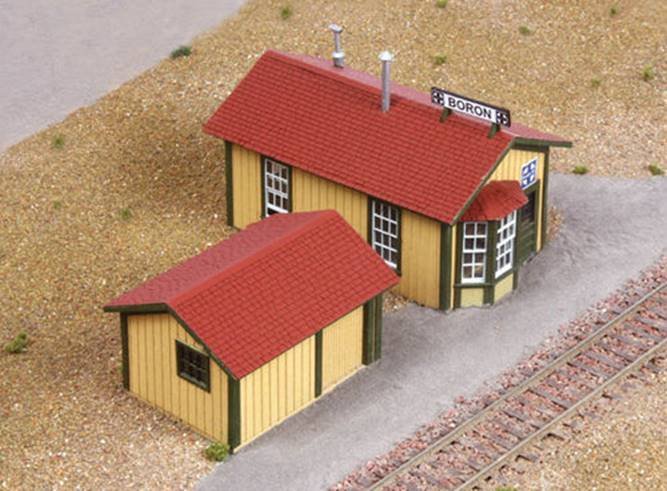
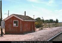
I finished the baggage shed drawings for the Boron Station. I started with the only two photographs I could find. One is a color photo of two sides of the shed, as of about 1995. The other is a picture out of the magazine I found the drawings in. Here is the color photo I found showing one end and the side with the sliding door. I heavily adjusted the original to highlight the battens so I could scale for the drawings. The battens are spaced 12 inches apart. The door is shown at the righthand side of the picture. The exposed door framing resembled that for a sliding shed door. This framing would originally be on the inside. I think the door used to have the standard tongue and grove siding when built in 1912. As time went on the siding started to decay, and they nailed a piece of plywood on the inside to strengthen it. By 1995, all the siding had decayed leaving the exposed framing shown in the photo. I CADed the door as having the original style siding. The shed was drawn as being 12 X 16 feet, as indicated by the battens, and I made the door opening the standard 82-inch height of a shed door. The door opening measures out at 30 inches, which is narrow for a standard shed door, but I went with the shown width. Here is the picture from the article, showing just a little of the opposite end on the station side. The portion of the window that is visible, shows that it is in the same position as the one on the side shown in the color photo, and that the pane was originally a 6 pane 2 vertical x 3 horizontal sash, like the ones on the station. I left the rear wall plain with no doors or windows. That seems correct for a building like this baggage shed. Here are two colored drawings of the shed, showing all four walls. Note that the photos showed exposed rafter ends. This was also typical of the standard Santa Fe shed designs. These next two graphics show the station and shed; in the general configuration they were in when at the Boron spur area. The red and black tiles/linoleum floor shown in the station, was what the station drawings showed. The graphics show the building as seen from the tracks. This last graphic shows the underside of the roof with the rafter ends. Now that I finished these drawings, I’m going back to CADing cannons, this time the British Commonwealth Pattern ones, from the mid to later 1600s.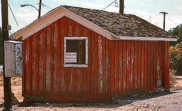
-
CNC-Model Making
thibaultron replied to Jefta's topic in CAD and 3D Modelling/Drafting Plans with Software
First, what do you want to do with the CNC? Are you making 3D parts, what materials, metal and/or wood? What type of machine CNC Router or a full CNC mill. Do You want high precision parts? What size parts are you planning to cut. Personal or commercial production plans. As far as software, I would recommend the Vcarve program (Pro if your machine will be bigger than 24" X 24") if you can design the parts on Sketchup, Fusion, or another 3D program. The other carving programs are subscription based, and not as powerful. Do you have a machine or are you looking for recommendations? -
3D Printing Cannons in Resin
thibaultron replied to thibaultron's topic in 3D-Printing and Laser-Cutting.
Here is a colored image, in as correct a set of colors I can get out of my CAD program.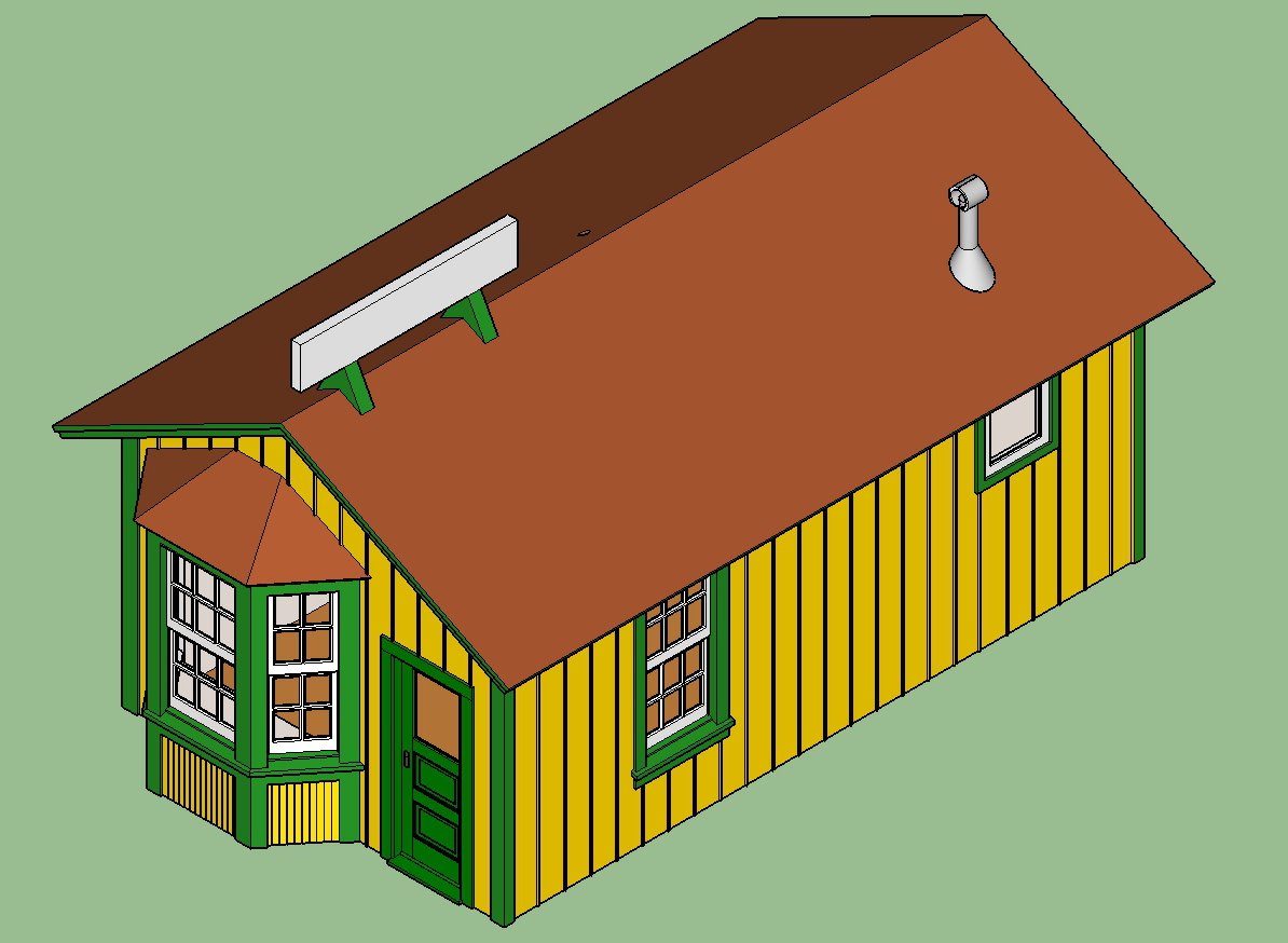
-
3D Printing Cannons in Resin
thibaultron replied to thibaultron's topic in 3D-Printing and Laser-Cutting.
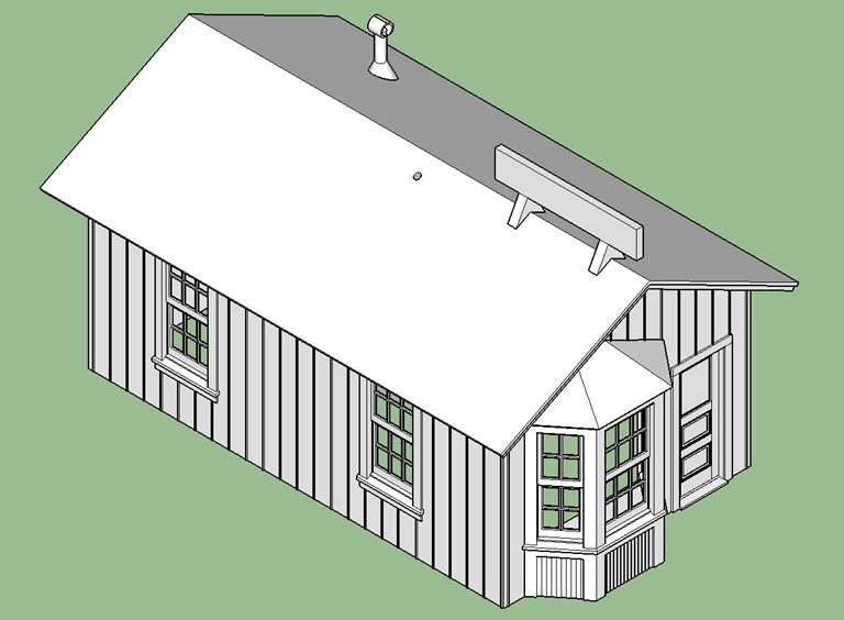
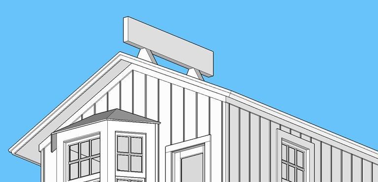
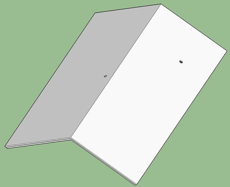
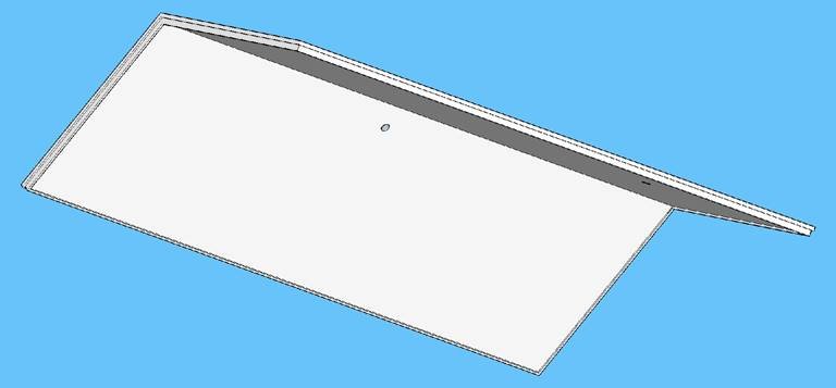
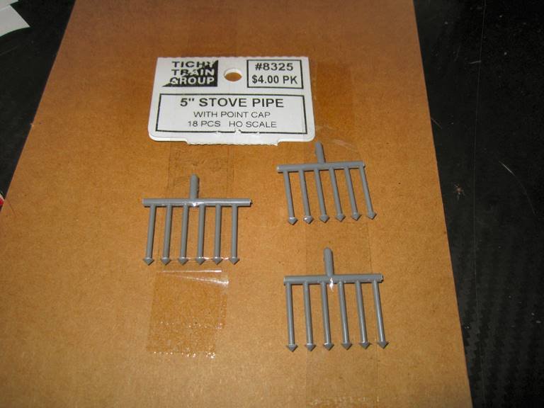
I finished the rest of the depot 3D CAD. I added the roof trim boards, both to the roof edge, and the wall to roof joint. I also drew the bathroom vent, a hole for the coal stove stack (which I bought 18 of), and the station sign and supports. Looking at these graphics, I have to add locating tabs to the underside of the roof.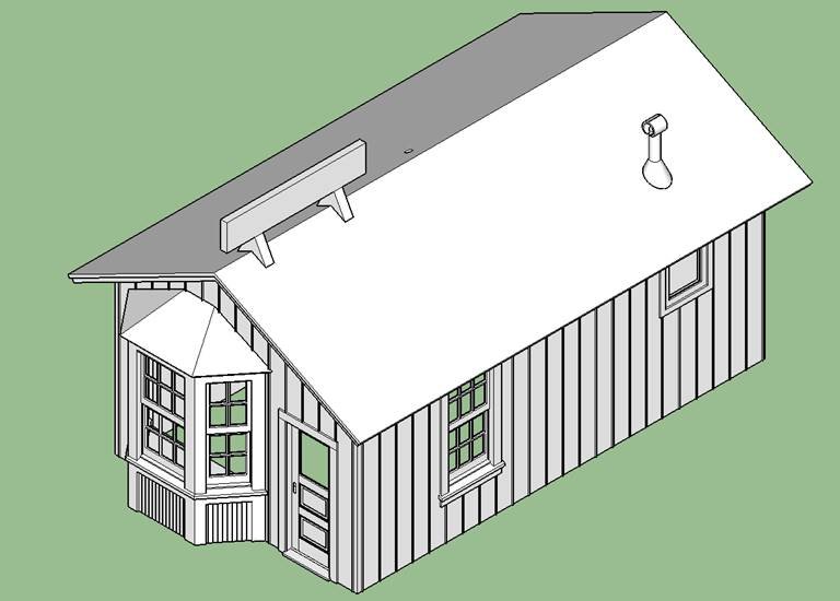
-
BR-18 Locomotive by Greg Davis - OcCre - 1/32
thibaultron replied to Greg Davis's topic in Non-ship/categorised builds
The boilers were of riveted construction, but were then covered with a layer of blanket insulation (generally Asbestos), and covered with sheet metal. The bands were used to hold the sheet metal in place. The only places without covering were the lower portion of the firebox, and (in the US, I don't know about other countries) the forward section that had the smoke box (the area that the smoke stack is). These were the external areas directly exposed to the fires. -
3D Printing Cannons in Resin
thibaultron replied to thibaultron's topic in 3D-Printing and Laser-Cutting.
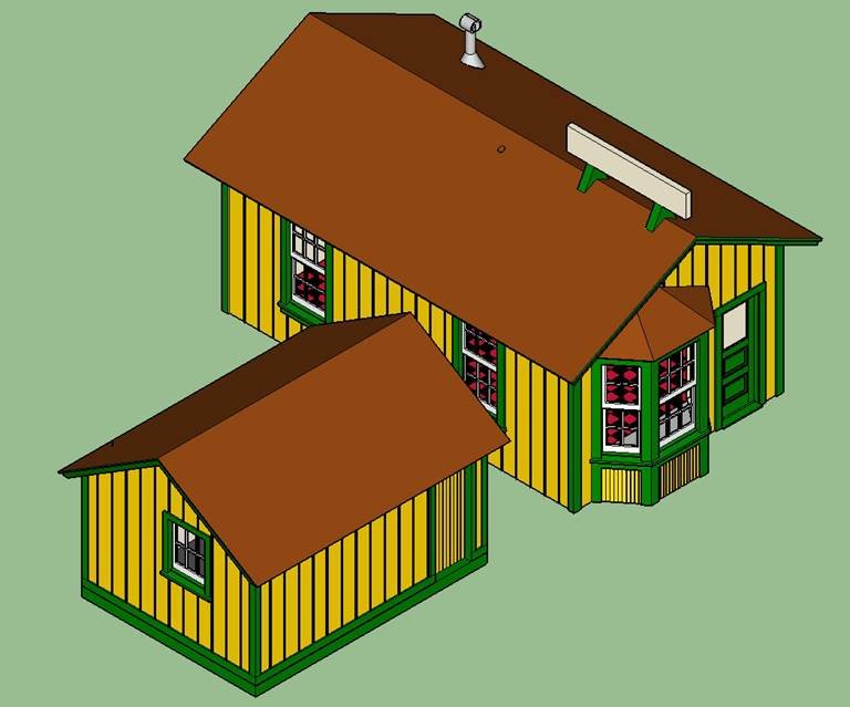
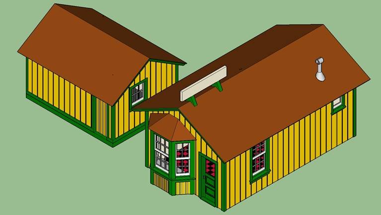
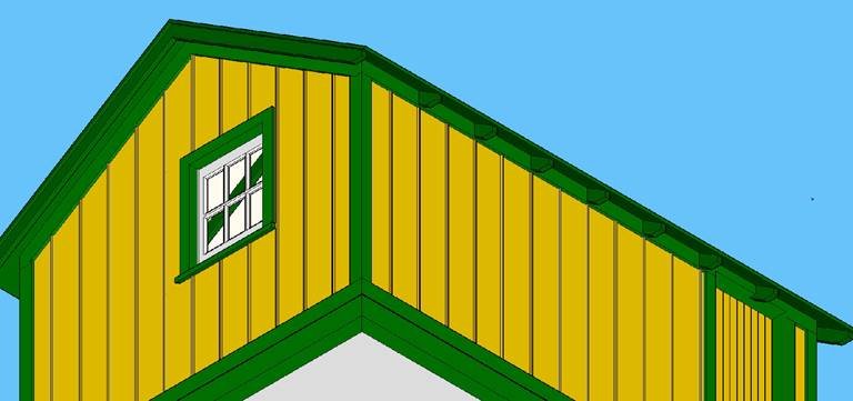
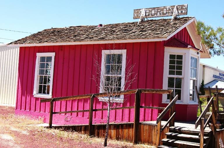
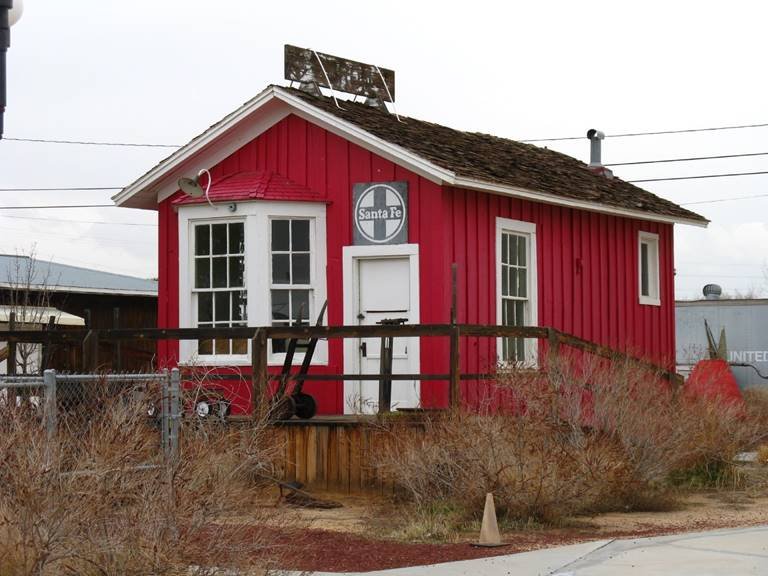
Santa Fe's Boron Station While not a cannon, I have been 3D CADing a small Santa Fe Railroad depot. This one serviced the 20 Mule Team Borax company spur. When I found the article with the plans, I thought to use spare parts from another kit to build it. After looking at the plans and the kit parts, though I found that the windows differed significantly, as well as the door. So, I decided to 3D CAD the windows and doors, based on the plans, and some sectional detail drawings from other Santa Fe books I have. After I finished the CADing, I checked the available Board and Batten siding in both the kit and those presently available commercially. I don’t remember just where I found it (should have recorded it), but the SF used 12 inch spacing between the battens, and the spare and new wood sheets all have ~11 inch as the spacing. With a small building this becomes more critical for it to look right. Board and batten siding is not all that complex to draw, so I did the walls too. I did make a couple of concessions. The wood sheets have square battens, and the Santa Fe use a rectangular batten with a molded face. Several of my other depot kits, use the standard sheets, so I decided to CAD the same. This gives continuity to all the depots. I’m not building this for a competition, just to add to the future display of various depots used on the SF. I do not want to CAD new walls for all of them! The second is that the walls and battens match the thickness of the wood sheets, though not the spacing, again in case the model is being built using just the detail parts. The windows and door are drawn as close to prototype dimensions, as my info allowed. The sashes are drawn with glazing putty installed per my protype info. I drew the windows as shown in the older photos and the drawing of when the building was in use. The museum photos show later repairs. Here are pictures of the station, as it appears today preserved in the 20 Mule Team Museum. The side walls have square battens, while the front seems to have a mix of both types, as well as variable spacing, I assume to seal cracks in the boards. The station has a few unique features from a “Standard” station, other than its small size. Instead of two six pane sashes like the front bay window, and other windows, the side bay windows are basically 6 pane sashes cut down to 2 pane wide sashes. The door is similar to, but not the same as a “Standard” pattern one. The small window on the right side of the building, is, as far as I can find, a one-off design for the interior bathroom. I got this on as close as I can, as the plans I have do not show this wall, other than to say it is 24 inches square. The trim around the windows also narrower than that around the other windows and door. I can only correct so much for the perspective using my available graphics programs and skill. Another difference is that it has wood shake shingles instead of the regular metal diamond pattern, or asphalt single used on other stations. This later makes it difficult to add as a CAD part, as I don’t want to draw several dozen different weathered shingles, and apply them one at a time, to a roof drawing. I looked up 3D printable files, but did not find any useful ones. I’ll just add them using a standard HO scale commercial product. While in service, the depot had a giant Swamp Cooler, that took up a large space between the large window and the bathroom window, on that side. The cooler was supported by a stand made up from what looks like any spare boards they could find. Designing that will take some effort, as the B&W magazine photos do not show the white, or light gray boards very well against the “white” building. At one time a laser cut kit was available for the depot, as well as the separate shed/baggage building, but has long been OOP. Even if I find one, I’ve done all the hard work already, so don’t need it. Here are some pictures of my progress, so far. I have all four walls and the bay drawn, as well as the windows and door. The bay is complete with the interior trim, and desk, as they will be visible from the outside, if you get really close to the model. The pictures show the walls and bay “Assembled”. I will likely print the walls as one piece, set upright in the printer. The bay will be printed in three pieces, the walls, the subroof, and the trapezoidal desk top. This will help to reduce the number of internal supports needed, and thus dimples from their removal. When the subroof is finished it will also be a separate part. I still have to add the corner and under roof trim. I’ve been waiting on those parts until I finalize how I want to print all the pieces. I will also be CADing the baggage shed. I do not have drawings for it, but do have pictures for 2 ½ sides. I have prototype photos of the two sides shown on the kit picture, and the lefthand side of the wall opposite the one with the window. That photo only shows the ½ with the window, but I think I can safely assume that those two windows and large sliding door are all the details present. I can get the dimensions by counting the battens, and using a SF shed sliding door. This graphic shows the four walls and the three pieces that make up the bay. The line under the bay walls is the desk top. The interior of the bay walls have locating tabs for the desk, as does the underside of the subroof. The next ones show the building from the front, showing the two side walls Here is the back wall, and the interior of the bay. I have not added any interior trim on the side or back wall windows. I’m not going to detail the interior. The window drawings have both the one-piece solid ones used here, and a version with the lower sash as a sperate part, this would allow it to be raised in a finished model, as well as one built using the wood sheets instead of the printed walls.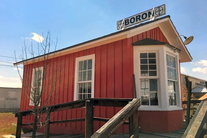
-
The Model Ship Builder Site has plans for a two deck battle station at: https://modelshipbuilder.com/projects.html Several years ago one of that forums members offered a limited edition kit (with their permission) and wrote up a practicum for building it. While the kit is long out of production, the praticum is also on that Web page.
- 1 reply
-
- 2
-

-
In any era ship, if you do not know the specific ingredients of the paint used at shipyard X in year Y, you will never get the "right" color. The best you can do is get a good representation, of the colors used. Also during the age of sail, the captain was allowed latitude to change paint colors, rigging, etc. to his taste (within bounds). I once worked with a contract engineer, who was proud to own a "Historic" farm in PA. That was until it came time to repaint it! As it was listed as historic, he was required to use only paint made the same as when the farm was new down to the exact formula recorded in the local Historic Society's records! He sold the farm, and bought a newer not "Historic" farm. He made money on the sale, and the new farm cost less than the cost of repainting the old one! I model the Santa Fe Railroad, and have many books listing the Santa Fe Standard Colors. The only problem, is that the records of the formula used for say "Santa Fe Yellow" have been lost. The best we can do is compare color photos, or possibly faded paint chips removed from existing buildings as references. Just use a nice flat red.
-
If I am building a long post, rather than a quick reply, I make a Word file of the post, and save it. Then I can finish it later. Once it is done, while still in Word, I select and copy the text, then paste it into the forum block. This has several advantages, especially if you are adding to your build thread. First, you are saving what you made, for your future use, without having to go back searching through the thread. Second, I generally create the post, save it, and wait an hour or so, and reread it, with a fresh mind. It is amazing how many mistakes I find, or decide that I need to change a section, to make it clearer. Lastly you can spell and grammar check it. It also helps you in a couple years if you can go back through the files on your computer to remember just how the heck you did X task. Also don't forget the great MSW crash! If this happens again you have all the files to restore the start of any builds you were in the middle of.
-
While you can't reach the petals, you can manually move the rudder and see the petals move.
-
For long thin parts such as the stick, 3D resin parts would likely be too fragile. The resin is brittle. For things like the pulleys, and the larger assemblies 3D printed parts should be fine. I don't think 3D filament printers could give you the smooth surfaced parts you want, and have much courser print abilities. For the stick mechanism, #d parts for the clevises and hinged parts should be OK, though you may have to fabricate the actual clevis tabs. The thinner shafts should be metal.


