thibaultron
-
Posts
2,951 -
Joined
-
Last visited
Content Type
Profiles
Forums
Gallery
Events
Everything posted by thibaultron
-
 Acetone, for sure. It will make the fairing of the hull difficult, if not corrected.
- 12 replies
-
- 3
-

-
- sakonnet daysailer
- Midwest Products
- (and 1 more)
-
Airbrush
thibaultron replied to Mike Dowling's topic in Painting, finishing and weathering products and techniques
Kurt; Tried your cleaner recipe. Works very well, thanks! -
Just got my copy today!! Can't say good enough things about the detail shown in the books. The only problem, is now I know my finished models will be much too clean! ;-)
-
My Spray Booth Construction
thibaultron replied to thibaultron's topic in Modeling tools and Workshop Equipment
Was finally able to do some testing of the booth today. Unfortunately neither my camera, nor my phone give good enough video to show the testing. However, here are the results: 1. The 250 CFM blower is too big for this size booth, 2' X 2' X 2', but it does not suck the paint stream when I paint, so, for now, I will use it as is. If I was to do it again, I'd get the 130 CFM blower. 2. The blower is also, I'm sure loader than a 130 CFM unit, but it is not objectionable. My cheap Harbor Freight compressor, on the other hand, is objectionably loud though! I need to get a long hose at put it in another room. 3. The baffle I added, helped in distributing the air flow evenly across the filter. 4. When I did a smoke test, with incense, there were no blowback areas anywhere in the booth. The smoke was drawn directly back in a straight stream. 5. During the summer I will have a nice breeze blowing past me! In the winter, maybe not so nice! 6. I think I will simply direct the output into a covered bucket, with relief holes drilled in it, for acrylic paints. There was nothing coming out the outlet, nor any smell. If I use solvent paints, then I will vent it outside. The blower would exchange the air in the shop, much faster than either my heating, or air conditioner could keep up with, if vented outside all the time. Another reason for a smaller blower. 7. This size booth is a better fit for my space than a 3’ wide one would be. I have another sheet of 3/8” plywood, though, so I may build the bigger one, just to see if I like it better. I have to build the table/desk next, and paint the booth. I have some aluminum flashing, white on one side, I may line the bottom with it, just to make paint cleanup easier. I also have to find a light to install in the top. 2 Like this -
Does anyone know if there is a difference between the 1970s and 2005 issues of this book?
-
One thing you did, but didn't mention, is that you used location bumps and indentations in your molds. The readers can see them in the corners of the RTV molds, in several pictures. For those who don't know what they are for, it is to align the molds. If you leave these out, getting them lined up so the casting will not have the two halves skewed, when you take them out of the mold, is extremely difficult.
-
My Spray Booth Construction
thibaultron replied to thibaultron's topic in Modeling tools and Workshop Equipment
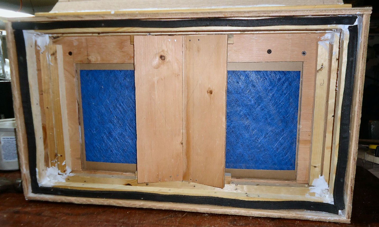
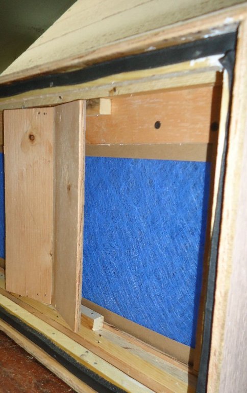
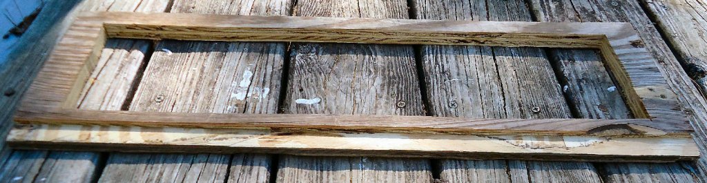
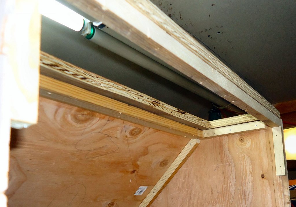
I cut the baffles from some of the left over ply siding the rest of the booth was built from. They are ~4” wide, set at a 17 deg. angle toward the back. I cut 4 short lengths of the ¾” square glue strips to add surface area for the glue. I figured that if I tried to glue just the baffles in, they would end up inside the fan. I used small brads to hold it together while the glue set. Here are pictures of the baffle I added. It will probably be next week before I can test the booth again. Once again work and family needs. Baffles from the back. And another from the front. There is about 1 3/8” gap between the rear of the baffles, and the front of the blower wall. This gives 35 ½ sq. inches of area in the gaps between both baffles and the wall. With about 18 sq. inches of area for the blower inlet, I think this is enough so that there will be little added restriction from the baffle addition. I bought some incense today, to use as a smoke source for testing, when the time comes, then a paint test.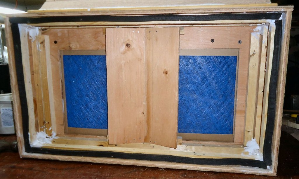
-
My Spray Booth Construction
thibaultron replied to thibaultron's topic in Modeling tools and Workshop Equipment
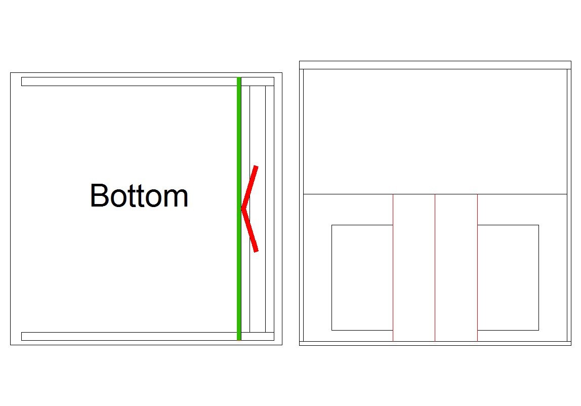
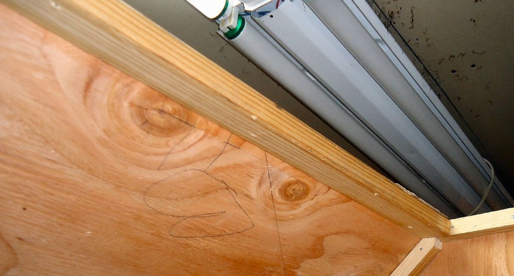
I tested the booth today, it seems to work OK, at least with me spraying water. The water was not highly visible though. Feeling the flow with just my hand, the area directly over the fan inlet seemed to have the most flow, not surprisingly. I decided that I needed to spread the flow over more of the back of the booth. So I’ve added two angled baffles just behind the center of the filter. I calculated the area of the openings left between the baffle edge and the blower wall. The total area is over 3 times the area of the blower inlet, so I should not be overly loading the fan. I’ll do more testing tomorrow, after the glue dries, and I reassemble the booth. I think I’ll go down to the discount store and buy some cheap incense to do a smoke test. Here is a shot of the drawing, I’ll add pictures tomorrow, or when I find the camera! The green bar is the filter, and the red bars are the baffles I added.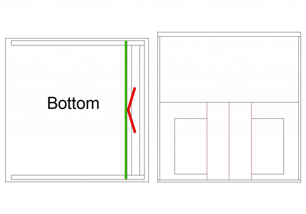
-
Airbrush
thibaultron replied to Mike Dowling's topic in Painting, finishing and weathering products and techniques
Kurt; The only Spic and Span I can find are liquid spray bottle type cleaners, lemon or citrus scent. Is that the type you use for your cleaner? -
My Spray Booth Construction
thibaultron replied to thibaultron's topic in Modeling tools and Workshop Equipment
Kurt; Thanks I'll try that when I can do some tests. It may be a week or so before I can do the testing. -
Airbrush
thibaultron replied to Mike Dowling's topic in Painting, finishing and weathering products and techniques
Kurtvd19; Thanks for the cleaning formula!! I be stopping by the store tomorrow! Where do you give your workshops? -
My Spray Booth Construction
thibaultron replied to thibaultron's topic in Modeling tools and Workshop Equipment
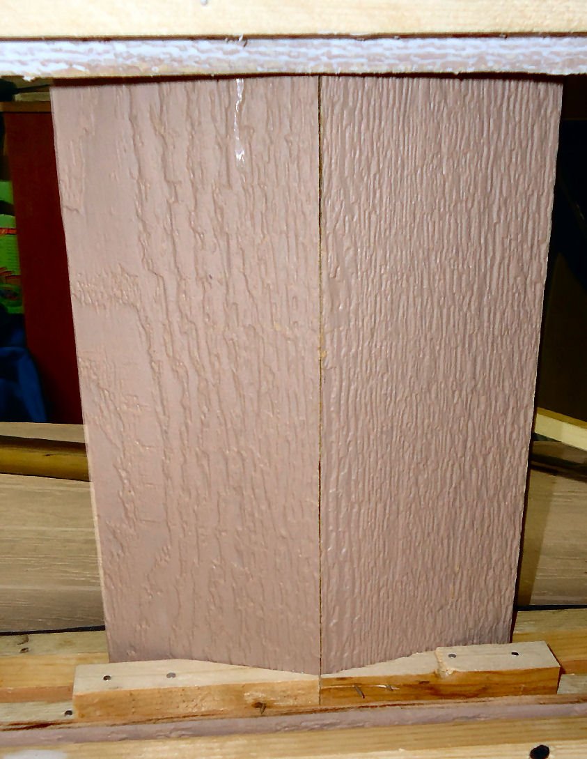
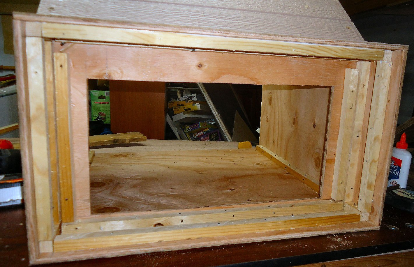
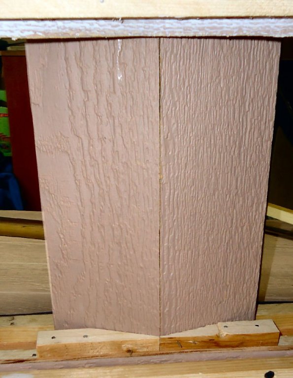
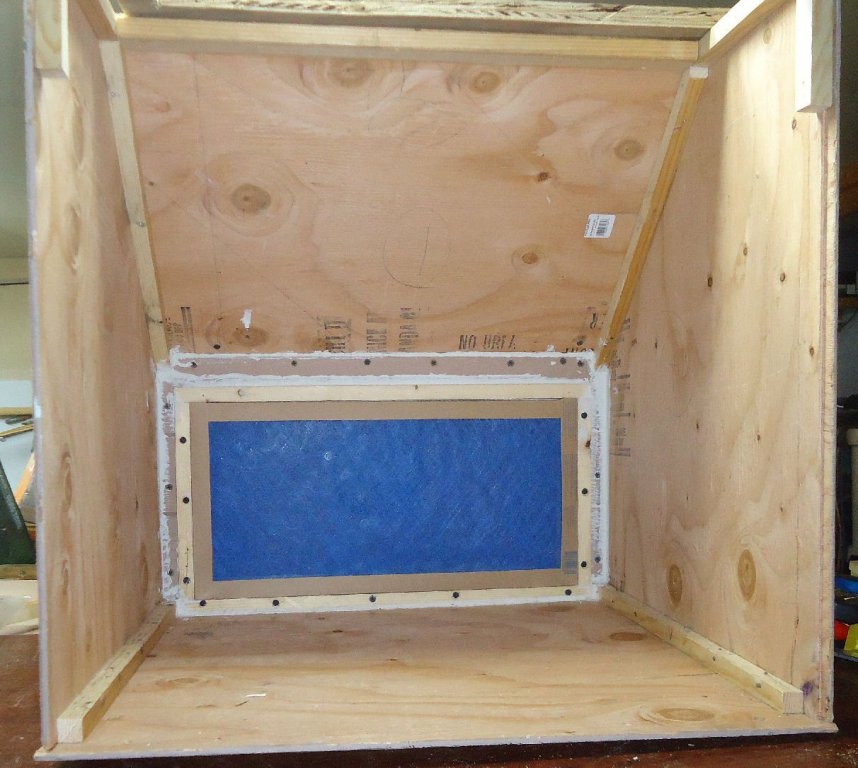
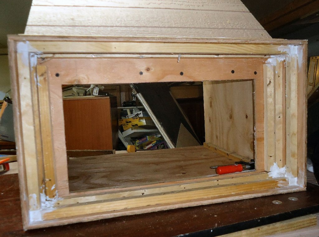
I “finished” construction on the spray booth today!!. The finished is in quotes, because it is still in the experimental stage. I temporarily used closed cell weather stripping to seal the blower wall, that is why it is sticking so far out from the rear edges of the booth. Here is a shot of the filter in place. The filter is 10” X 20”. The top filter frame piece is screwed in from the back. I’ll paint it after I test paint a model, and see how it works. Just feeling the airflow by hand, indicates that the blower may, indeed, be too strong for this size booth. It may be a week or so before I can paint something, as family and work needs may interfere.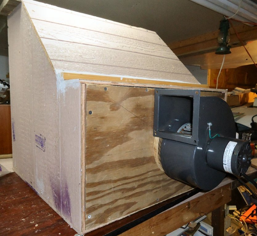
-
My Spray Booth Construction
thibaultron replied to thibaultron's topic in Modeling tools and Workshop Equipment
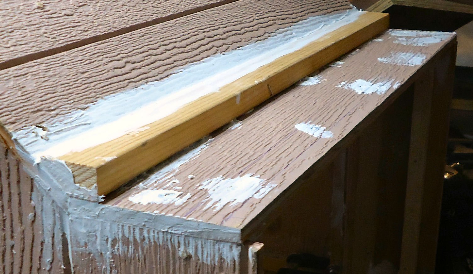
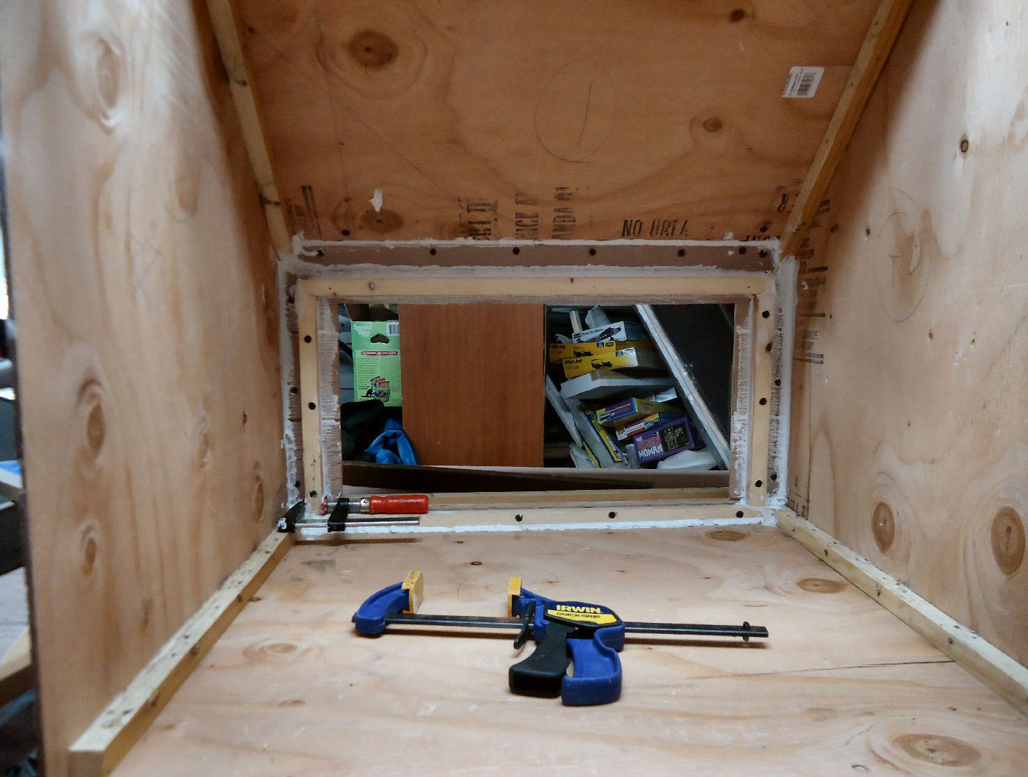
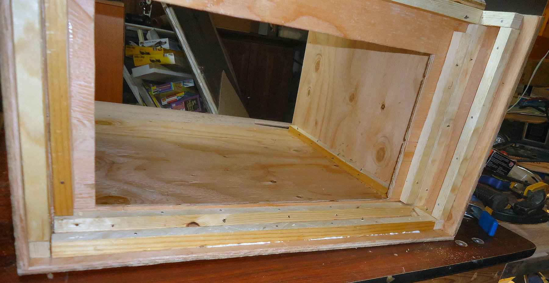
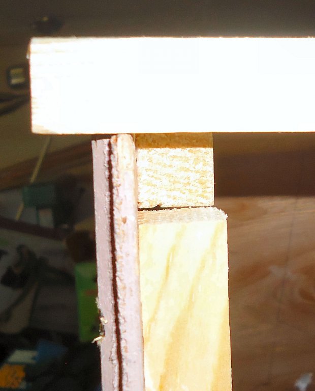
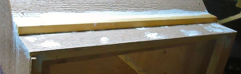
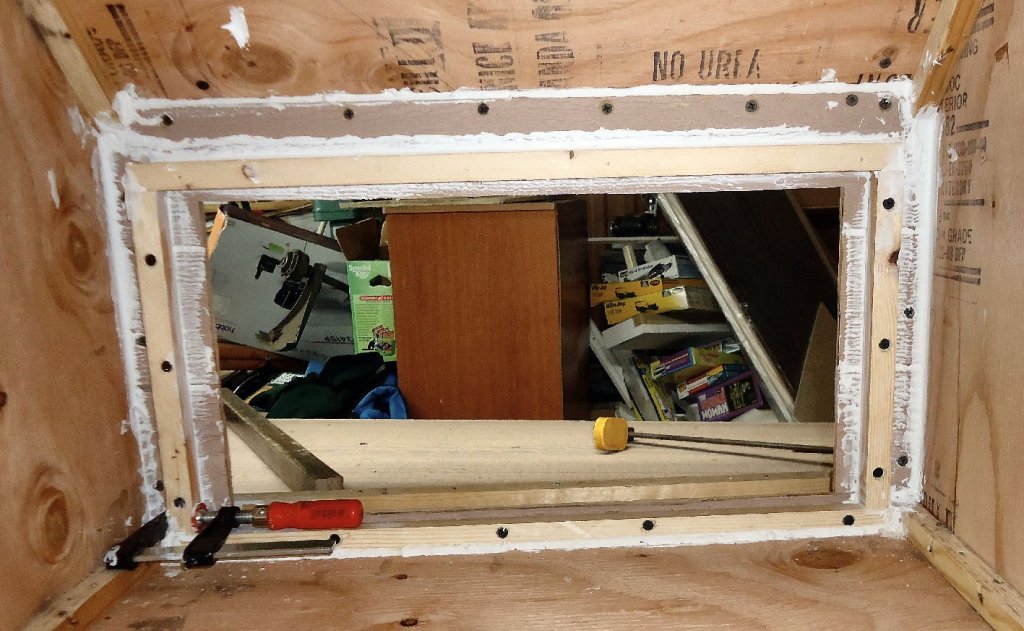
I caulked the booth today, and re-cut the top to make the light opening larger. I also used the Dremel to cut off the tips of the screws that protruded into the interior. I limited the caulking to the filter mounts, and the blower chamber. Any air that may leak in around the joints of the spray area will not have much of any effect on the performance. I had planned to make the cover of the blower chamber removable, but decided that it should be permanently attached. I can access the whole thing from the blower end, as the blower wall is removable. I caulked as much of the chamber as I could get to. I caulked both joints each glue strip made with the inside, and along the outside of the chamber cover. With everything glued, the caulk may not have been necessary, but it won’t hurt. I installed strips to hold the filter in place. I cut them so that the filter is a light press fit. If needed in the future, I will add some kind of tabs to hold it. I caulked around the outside edges of the filter wall, and the outside of the filter strips. The joint at the top of the filter wall, blower chamber cover, and sloped back, got special treatment. I filled the joint from the top, then added more along the top of the filter wall. Next I added an angled strip to fill the gap at the cover / sloped back joint. This was not glued, but set in a bed of caulk. I then turned my attention to the booth top piece. I decided that I needed to make the light “hole” larger. I trimmed it so that the back and sides were 1 ½” wide, and the front 1”. This piece will be hinged to the sloped back using a piano hinge. The top is ¾” plywood and the sloped back 3/8” ply. I needed to cut a rabbet in the back of the piece, so that the hinge will sit properly. This is shown to the bottom of the picture, above. I attached another piece of the angled glue strip along the booth top / sloped back joint. It provided stiffening to the plywood edge of the back, a seat for the top, until I install the hinge, and a slightly better seal to the joint. The plywood used for the booth was warped, and the tips at the top front turned in. So that the top would fit correctly I added a removable brace to the front. The top is hinged so that I can get better access to the top of a model, and a permanent brace would interfere with this. I simply screwed a couple of short pieces of glue strip to the front of the booth, and the brace sits in the gap between these and the strips along the top of the side walls. It pushes the tips apart about an inch, as can be seen when I just sit the brace on top, without forcing it in place. This is a photo of the top and brace in place. With just the overhead shop light shining through the top, you can see that the interior is well lit.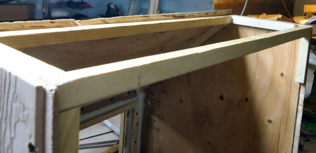


-
My Spray Booth Construction
thibaultron replied to thibaultron's topic in Modeling tools and Workshop Equipment
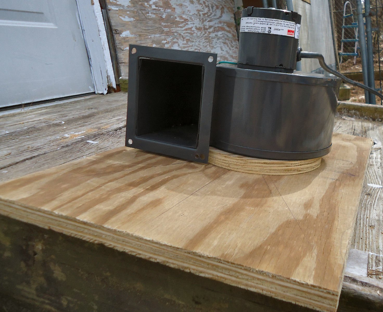
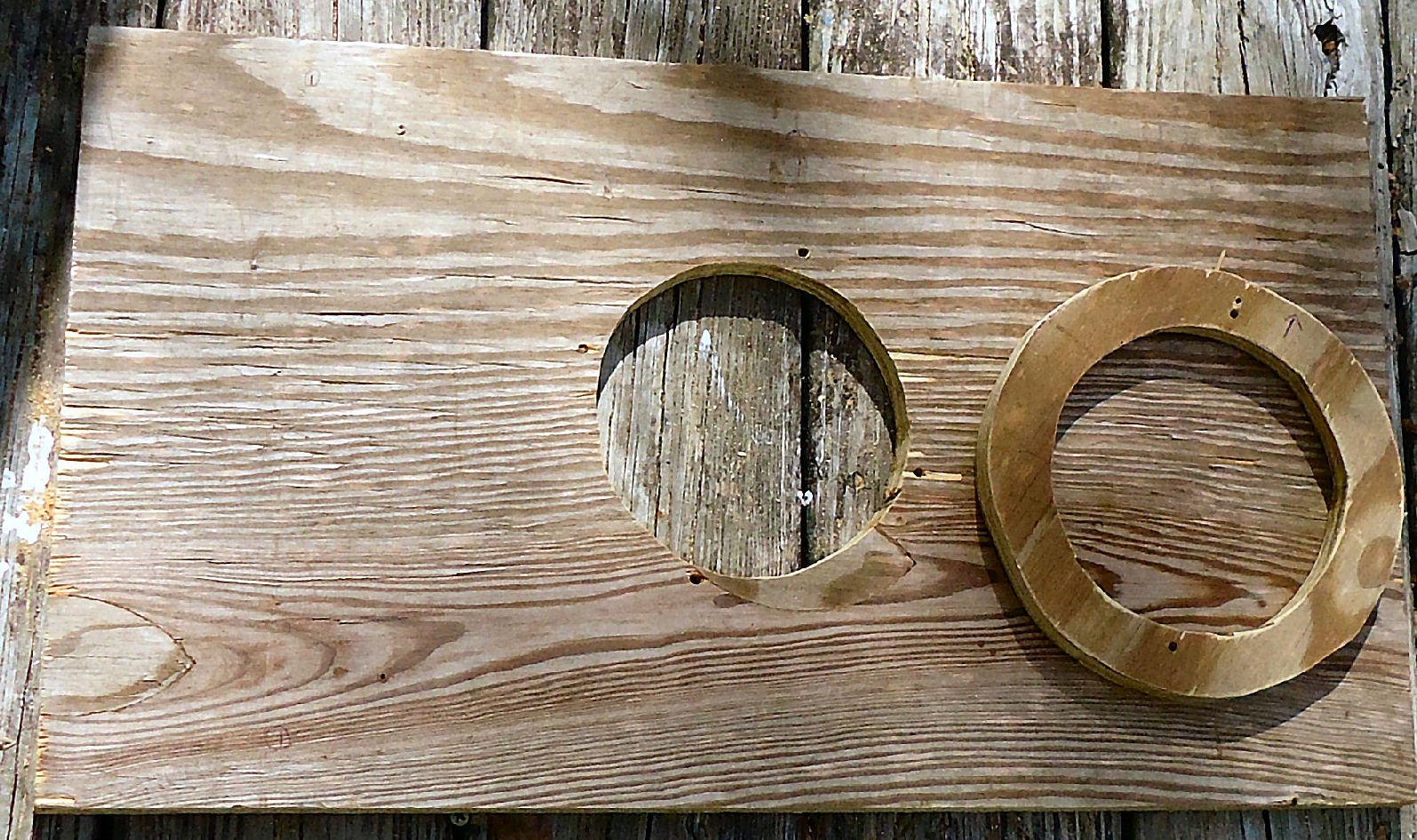
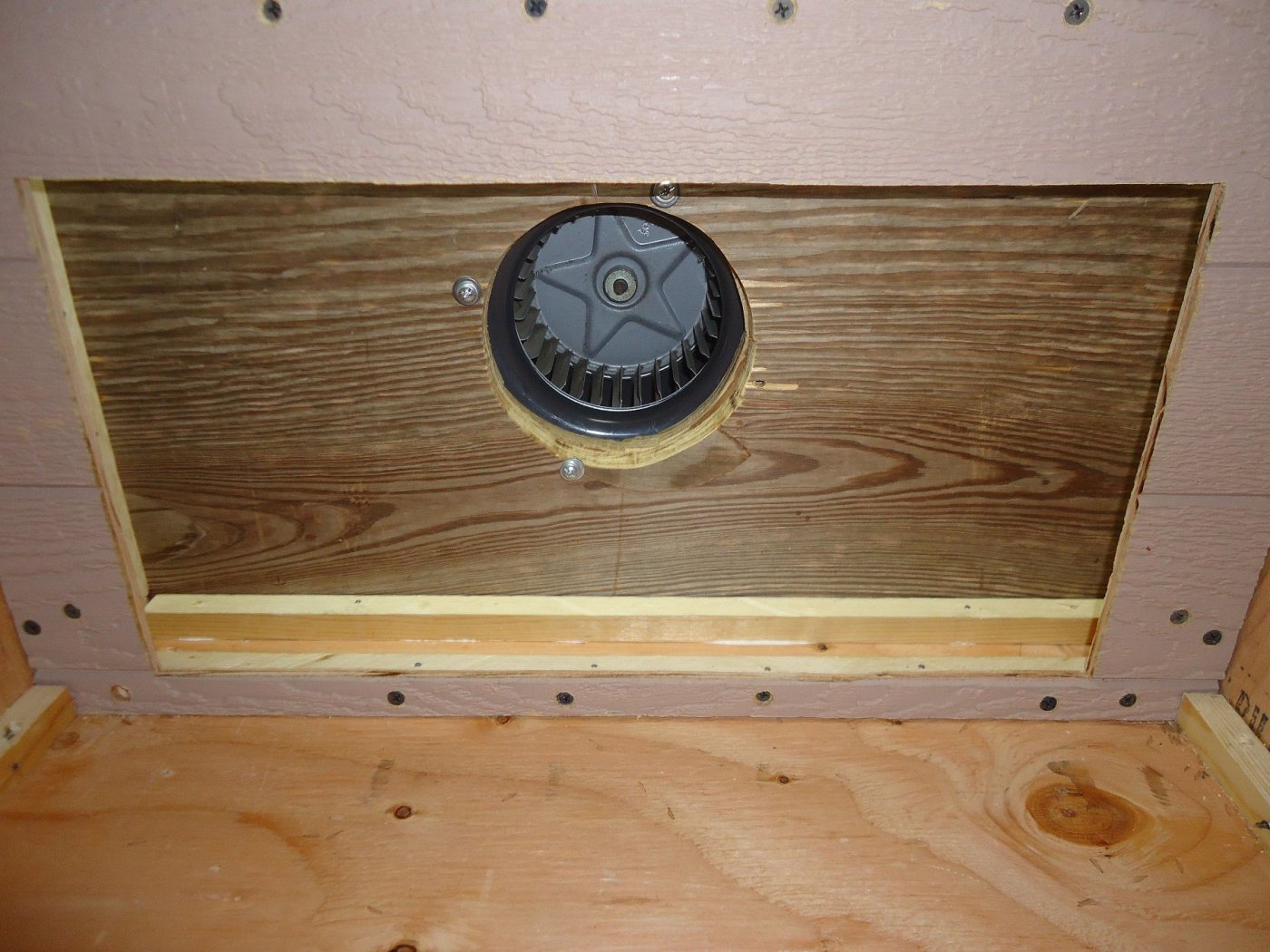
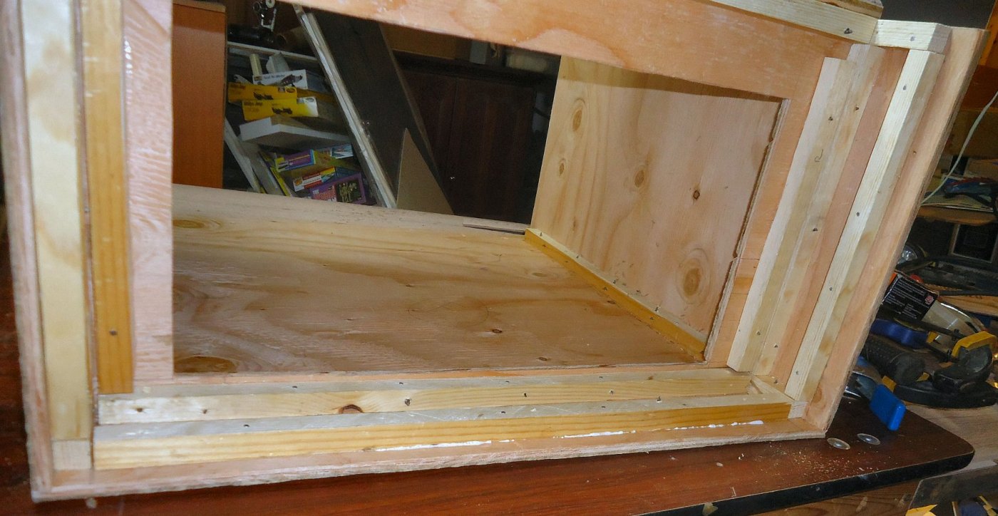
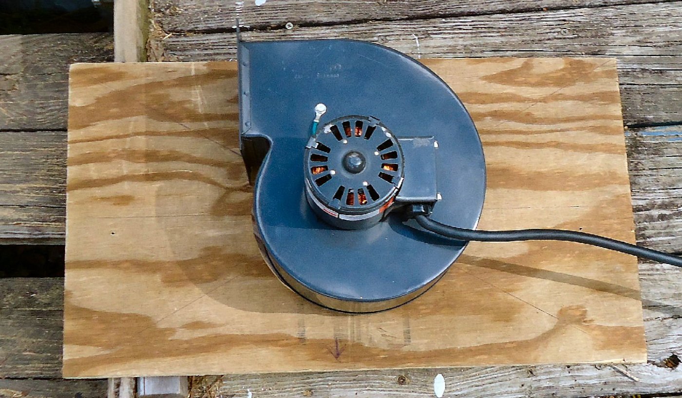
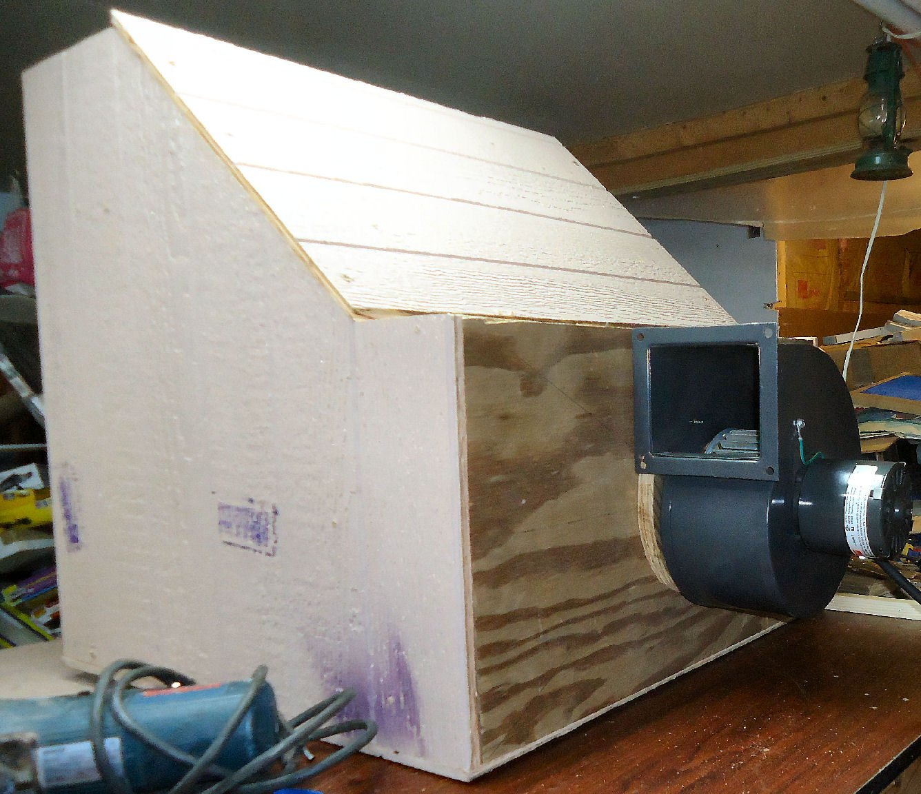
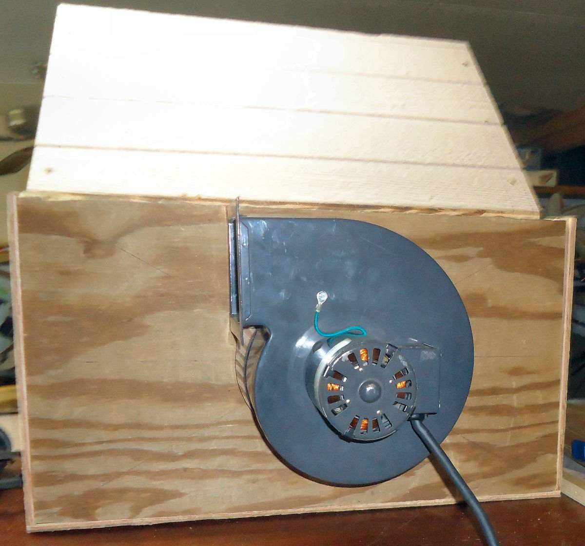
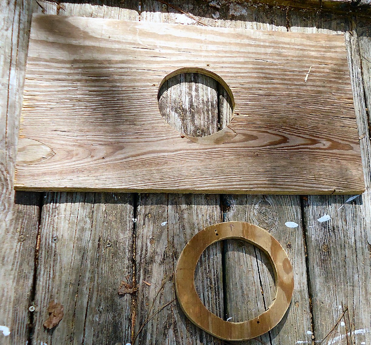
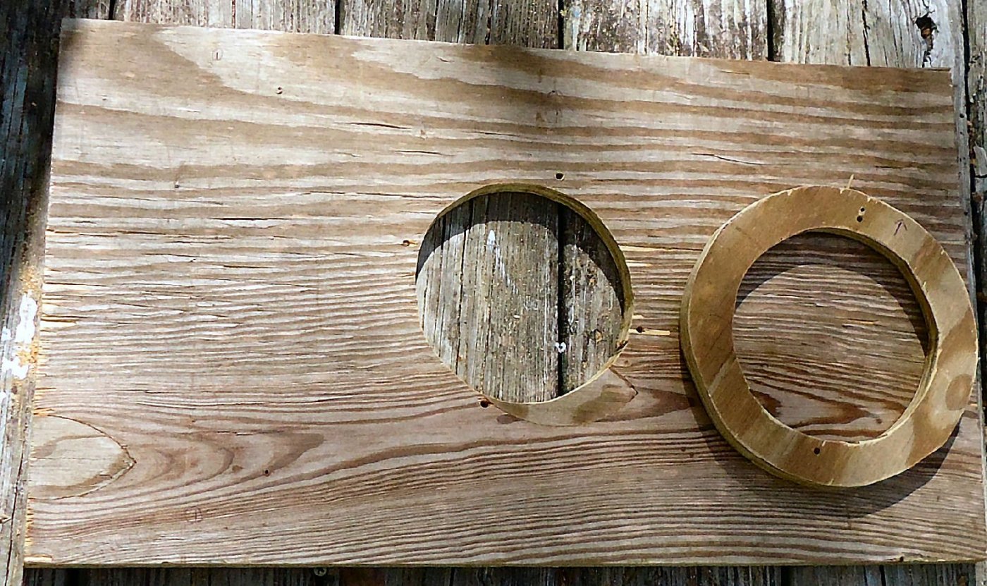
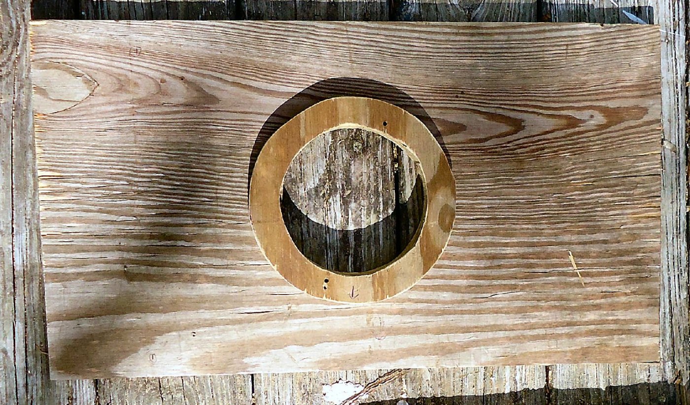
The blower came in the mail, and I compared it to the drawing I had made from the manual. Except for a few minor details they were close. The only important difference was in the position of the screws holding the inlet ring on. In the manual, there were 8 holes set square with the body. On the blower I got, there were only 4, offset by 72 deg. from square. I waited for the blower to arrive, before cutting anything, so this wasn’t a problem. I wired on a plug, and tested the blower. Kurt has a point. The blower may be too powerful for this size booth, but I’m going to finish it, and see how it performs, with this blower. As I mentioned before I am going to mount it with longer screws through the blower wall, into the holes normally used to mount the inlet ring. As you can see the blower cannot be mounted flush with the wall, as the flange on the outlet protrudes past that surface of the housing (lower right). To overcome this I am placing a ¾” thick plywood ring between the housing and the wall. I had originally thought that I would have to have some sort of metal ring on the inside of the wall, so that the screws would have a stronger seat. After mounting the blower though, I found that there was more than enough wood surrounding the screws, to prevent them pulling through, using just washers. I cut the hole for the opening in the wall, and the wooden ring out with a saber saw. I would like to give a nod to a very nice saw that I borrowed from my neighbor. It is made by Bosch. That is the smoothest running saber saw I’ve ever used. Here are two shots of the pieces, and another is of them arranged as they will be when assembled. Note that at this point, I’ve already drilled the mounting holes. I took some care in getting the cuts smooth, but I didn’t go back and sand everything to a furniture grade finish. I printed out my drawing, and attached it to the wall, at the marked center of the board. I then drilled the first hole per the drawing. Then I placed the inlet ring with one hole aligned with a drill bit in the hole, and the other holes aligned with the ones on the drawing. Using the ring as a guide I drilled the other three holes. I then cut out the opening, and the ring. I clamped the wood ring in place and drilled the holes through it. Luckily I managed to get them all straight through both pieces, and the screws matched the holes in the housing. I drilled them by hand, as my drill press is buried at the moment, so I was quite pleased that they all came out correctly. I then mounted the blower using 2” #8 sheet metal screws, and a #8 and #10 washer under each screw head. I thought I was careful in getting the blower on correctly, but notice the arrow drawn on the blower wall in the first picture. It should be pointing up. Yes, I mounted the blower upside down! I then disassembled it all and remounted the blower correctly. Normally this wouldn’t matter, but the spray booth is not entirely square, and the wall will fit only one way, and I need the blower outlet to point toward one specific side of the booth. As I’m facing the front, the outlet has to go toward the right hand side (the left as seen from these pictures looking at the back of the booth). I then temporarily mounted the blower and wall to the back of the booth. I will not be gluing this wall to the booth, but attaching it just with screws. I may have to remove it in the future for maintenance. I put it in place so that I could attach the glue strip along the bottom. I waited for this until now, to make sure everything would line up. Here are three shots of the blower and wall put into place, while I was doing this. These shots are with the wall just wedged in place. I used clamps to hold everything tight while I was putting in the glue strip. You can see in the pictures that the wall is sticking out a little at the top, before I clamped it tight. The next two pictures are of the installed glue strip. The first is from the front with the wall still clamped in place. The second is from the back with the wall removed. In the first picture you might notice that there are only three screws installed. When I went to the hardware store I asked for 4 #8 screws and 4 #10 screws. The #10s were in case I needed a larger screw than I thought. What they gave me was 3 #8s, 3 #10s, and 2 #12s! I went back later and they gave me another #8 free. One thing I forgot to do was wipe the glue where it had squeezed out! I got called out to do something else and forgot to do that. I may have to do some cleaning up of that area. I initially attached the strip with a few small brads in predrilled holes (as seem in the photo). After this shot I clamped the piece in place, and screwed it in from the bottom. The inlet ring is mounted against the housing (the way it comes from the manf.), not on the inside of the wood pieces. I have seen some booths where this was done. The inlet ring seals off the larger housing opening, and extends down close to the blades. This keeps the air from blowing back out this area. If you mount it on the inside of the wood, this pulls it way from the blades, and allows a large amount of blow back, into the booth, like leaving the end of the balloon open after blowing it up. Next time I’m going to work on the top cover of the blower box, and install mounts for the filter.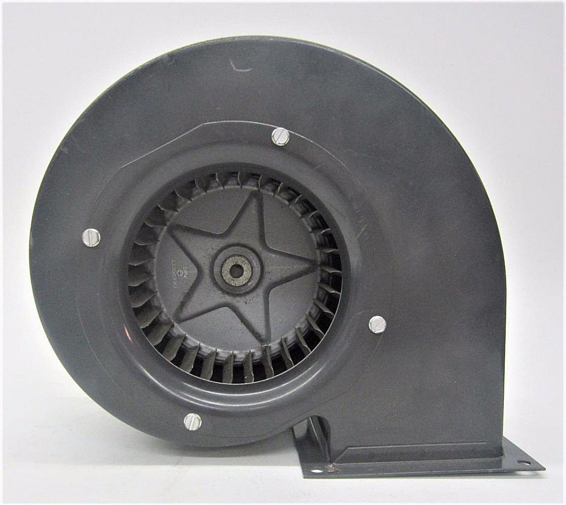


-
Thanks for the heads up. I just ordered it!!
-
Airbrush
thibaultron replied to Mike Dowling's topic in Painting, finishing and weathering products and techniques
Don't use brushes! Here is a talk by the owner of Badger Airbrush. Great info!- 56 replies
-
- 11
-
-
Though written for metal casting, the following book will give you ideas on how to make molds for complex parts. Just use RTV rather than sand. http://www.hnsa.org/resources/manuals-documents/single-topic/foundry-manual/ The ultimate graduation test was making a saucer, and tea cup, with a spoon sitting in the cup as all a one piece casting, not assembled as separate parts.
-
My Spray Booth Construction
thibaultron replied to thibaultron's topic in Modeling tools and Workshop Equipment
For an explosion proof blower look at marine engine housing blowers, rated "Ignition Proof". There is a Coast Guard standard for them. They will need a 12V 5AMP or more power supply. -
My Spray Booth Construction
thibaultron replied to thibaultron's topic in Modeling tools and Workshop Equipment
James; The booth is not explosion proof, just resistant. The blower motor is on the ouside of the blower housing, not in the air stream. Canute; The vent I'm going to use has the screen built in, and a flapper, like a drier vent. -
My Spray Booth Construction
thibaultron replied to thibaultron's topic in Modeling tools and Workshop Equipment
The blower arrived today! It was close to the drawing I had, but not exact. I'm redoing the drawings, then this weekend, I'll get it attached. -
My Spray Booth Construction
thibaultron replied to thibaultron's topic in Modeling tools and Workshop Equipment
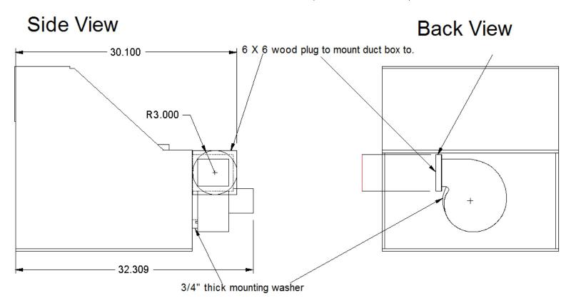
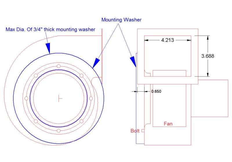
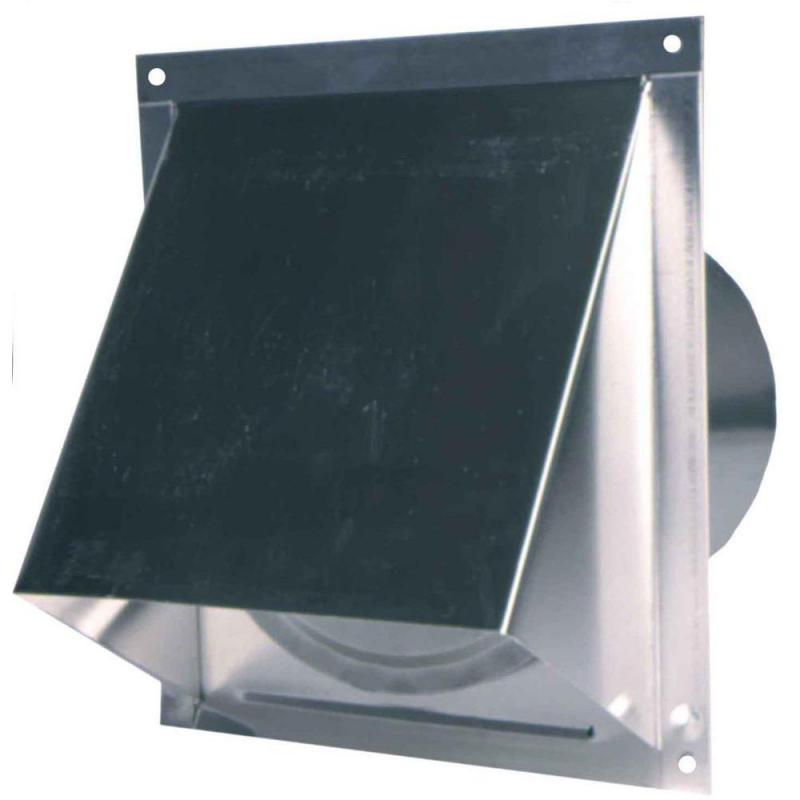
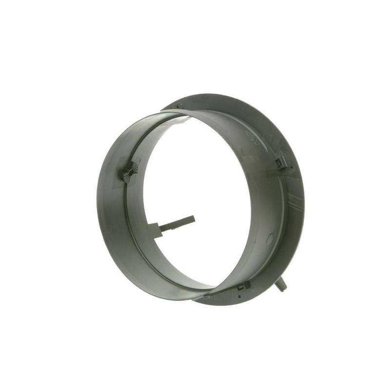
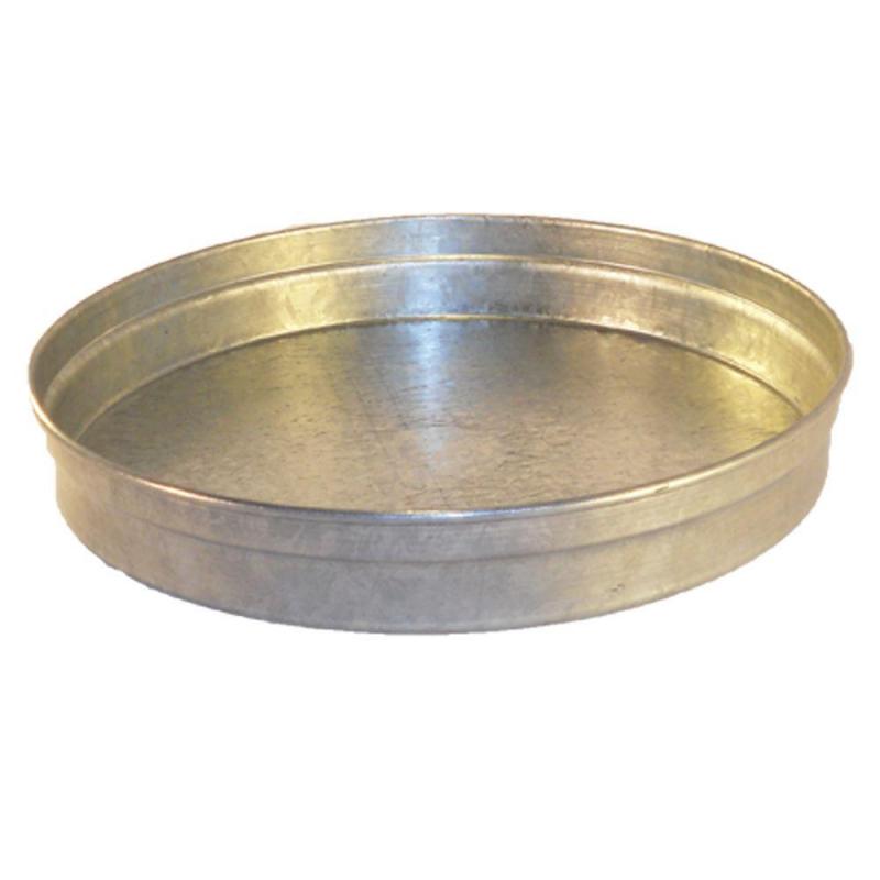
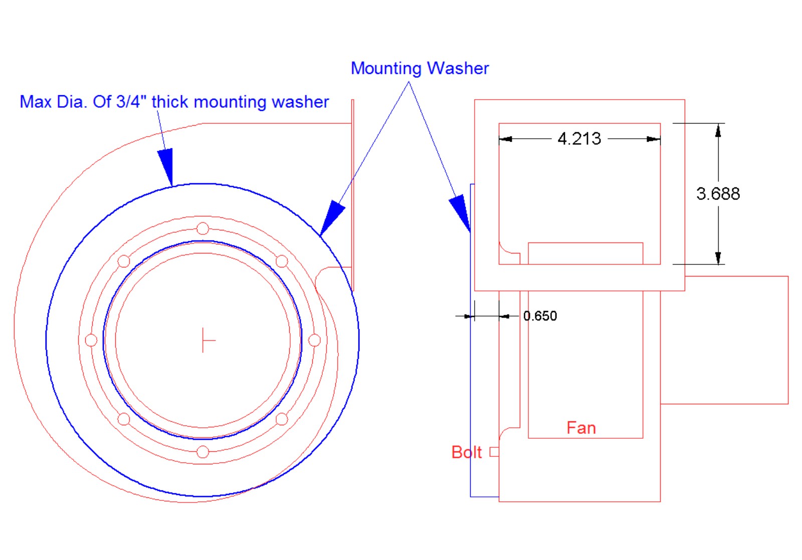
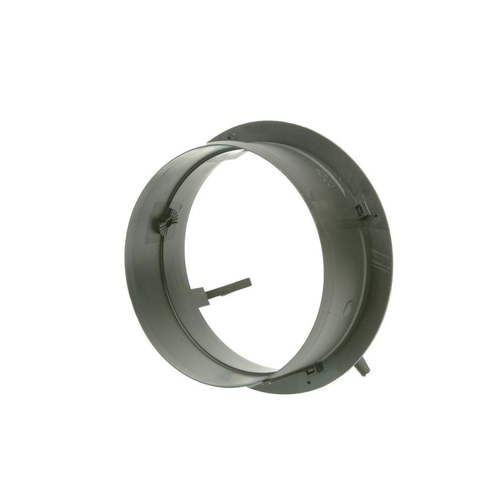
I found a manufacturer spec. sheet for the blower I bought, and have determined my initial design for mounting and venting it. Here is the drawing I made from it. The blue washer I’ll explain later. The inlet diameter of the blower is ~4.8”. I didn’t want to just have the mounting bolts sitting directly on the blower wall wood, I’d like to have a metal ring, to spread the weight, and keep the bolt heads from working down through the wood. There is an inlet ring that has a funnel shape that comes down close to the blades. My initial thought was to simply use this inside the booth as the metal support, but then I realized that this makes a seal to prevent backflow. Looking on the net, I found a 5” duct bulkhead like fitting. So I plan on having the flange of this as the metal support ring. I’ll trim the duct portion to fit so that it stops just short of the inlet ring. Have been watching a video series where the guy did use the inlet ring inside the booth, and he had major blowback problems. For the outlet plumbing, I’m going to use 6” duct. The blower outlet is about 3 1/4” X 4 1/4”, so this should give me a low restriction flow. I’m not sure which of the two ways below, I’m going to use to adapt the outlet to the duct. Fashion a round wood plug that bolts to the outlet. The duct will fit over, that then be secured with screws. Use a metal end cap, and cut out the center to match the outlet. I was leaning toward the wood plug, but the cap would be stronger, and not much, if any, more effort to make. I also found a 6” duct wall vent. Like a drier vent on steroids. Back to the blower mount. The blower can’t just be bolted directly to the booth wall. The outlet flange would hit the wall. So it has to be held away from the wall. I plan to use a ¾” wooden flat donut, for the spacer. This will get the outlet flange just clear of the booth wall, and provide a good seal between them. So the mount will consist of: The 5” bulkhead mount,(trimmed), the wall, the donut, and the inlet ring, where it is supposed to go. I was thinking of using all 8 of the available inlet ring screw holes, but just the four actually used by the manuf., should be enough. The other four are provided so that the blower can be rotated 45 deg., if needed from the holes in whatever equipment it attached to. Here is a drawing of the blower mounted to the booth. When the blower actually gets here, I’ll double check the measurements.