


thibaultron
-
Posts
2,644 -
Joined
-
Last visited
Content Type
Profiles
Forums
Gallery
Events
Posts posted by thibaultron
-
-
Mine is an Atlas 12 X 36 one. Finances dictate the sale, unfortunately. Maybe some day I will be able to get a small one.
-
Thanks for the information on the furling on sharply raked masts, my present build has such a mast.
-
Part 19
Back to the engine.
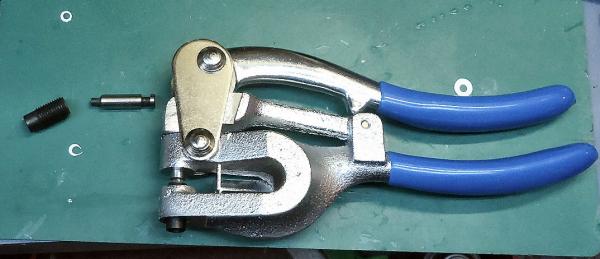
I started with the flywheel. It is 14” in Dia., at full size. The rim inner dia. Is 10”, and ideally is to be 2 to 3” thick. I used a Harbor Freight hand punch to make the parts. First I punched out 7/32” disks from .020” styrene modeling sheet. Then I punched out some from .014” plastic from a hardware store “For Sale” sign. I tried using .010” styrene, but the pieces came out too ragged.
Normally I avoid using the sign plastic for modeling, as it is too soft. But in this case it punched well. I normally use it for airbrush painting practice. For a $1 or so a sheet it gives a lot of surface area to play with. I can also try out colors and effects, before I use them on a model. I’m just starting out with the airbrush, so cheap practice material is helpful.
The punch leaves a small dimple in the center of the disk. I used this to help center the piece when I punched out the center to make the rims.
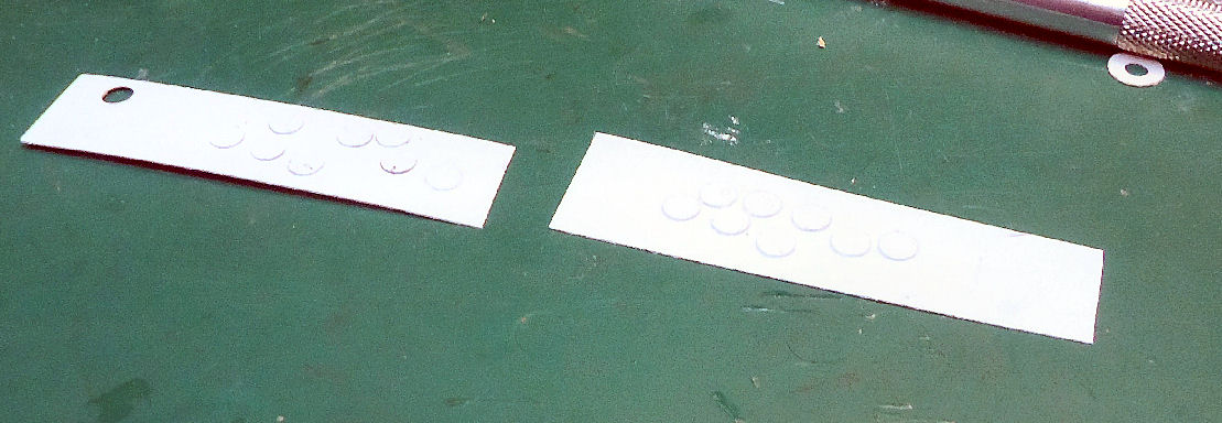
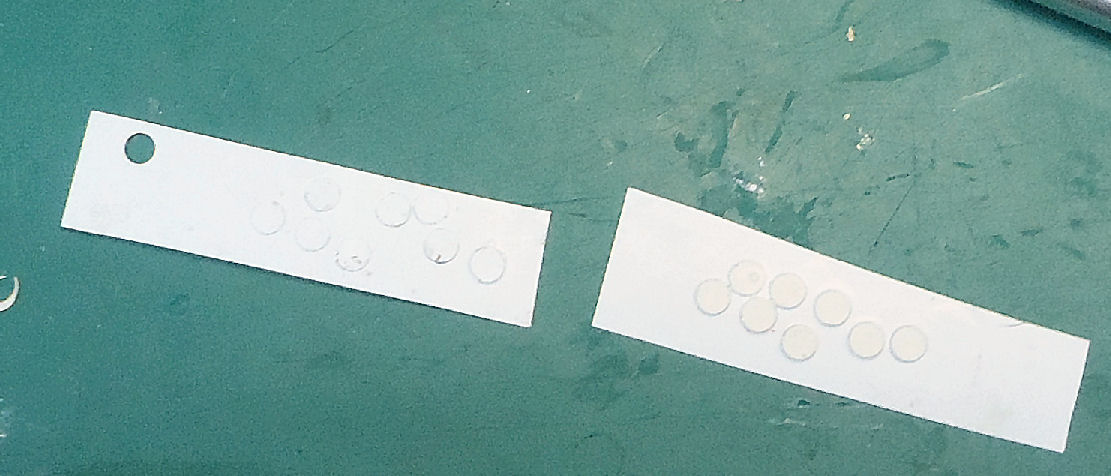
I glued the disks to a piece of sign plastic with white glue, and let it dry overnight.

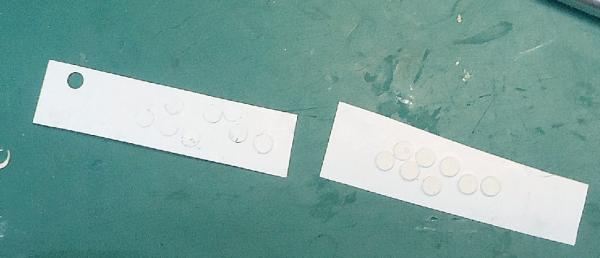
The white on white is a little hard to see in the photos.
Then I used the center dimples to locate for the 5/32” hole. The .014” plastic had released somewhat making the center harder to find on some of the disks. I had to used both hands and magnification for this, so no pictures.
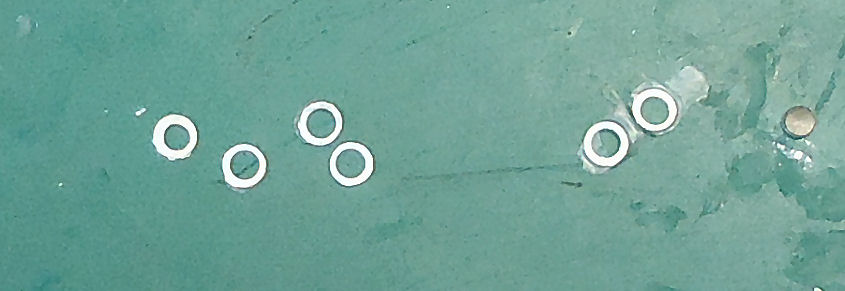
The punch “stud” has a small point. I partially pressed the handle until there was barely clearance to slide the plastic in, then I squeezed until there was a little drag, and tried to get the dimple to catch on the point. Out of 10 or so pieces I managed to get two or three acceptable rims.
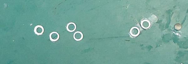
As you can see at the left, some were close, but still too much off center.
I punched out some 7/32” plain disks for the center web of the flywheel.
I glued a rim on either side of a web, and placed weights on them so that they would be flat.
I made flywheels out of both three layers of .020” (about 4” total thickness scale), and .014” (about 3”) and will pick out the one that looks best with the engine body.
Unfortunately the punch did not have the dies for the 4” axle boss I want, and I don’t have any really small metal rod or tubing. I’ll see what I can do for this, as I go on.
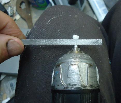
Next I shaped the cylinder head. I chucked a sprue piece in my battery drill, and using a regular small flat file, and a flat needle file, I reduced the diameter to 3/32” (6” scale) for the cylinder head where the water jacket will be.
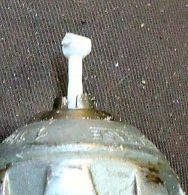
For doing this I placed the drill on my lap and held it with one hand, and filed with the other. Not the best way, but it worked.
I had left the blob on the end to shape the crankcase with, but messed it up. So I cut it off and reduced the end to 1/16” (4” scale) for the non jacketed bottom of the cylinder head.
The picture is a little blurry, my camera has problems with these small parts.. The black section is the water-jacket area. I colored it with permanent marker before starting the filing for the smaller section. The white upper part is the section I reduced to 1/16” (4” scale) for the exposed area of the cylinder head.
For the crankcase I printed the pattern and glued it to a piece of .040” plastic sheet. The final thickness will be greater, but it is easier to cut a series of thinner sheets than an .080, or .100 thick small part.
After the white glue was set, I rough cut the piece along the sides, leaving a long tab at what will be the bottom of the engine. This will be used as a handle until most of the other operations are complete.
This is the second attempt. The first time I cut it too close to the lines, and the top was not wide enough to match the cylinder head.
I read an article several years ago about a highly detailed and highly complex armor model that had been built from scratch. The builder said that during the construction, he had probably thrown away another model’s worth of unsatisfactory parts. I try to keep this in mind. I stop when mine are only slightly unsatisfactory. :-)
Then I glued this onto another .040” piece.
When the glue had dried I cut off the extra at the sides, and sanded them square. Using the cylinder head part as a guide I cut the top flat, leaving some on either side to represent the mounting flange.
Looking at the final width of the top verses the thickness of the crank piece, I decided to add another layer of .020” plastic. A little final shaping and the top of the crank case was done.
I did not have any small 1/32nd rod (2” Scale) for the crankshaft, but found a “T” pin with the right diameter. I reattached the paper pattern, which had come off during the shaping, and used it as a guide for drilling the shaft hole in the crank case. I used a #70 drill, but the size would depend on what you had to use. This left a tight fit to the pin.
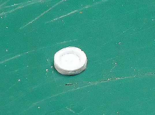
To smooth the outside of the flywheel rim, I cut down the end of a dowel to fit inside the rim, and glued it to the flywheel.
I will admit to cheating a little here. I used a metal lathe to accurately reduce the dowel diameter, as I did not have a dowel the right size. I’ve avoided using it before in this build, as many do not have one, and I am selling mine, so will not have one in the future. In this case the dowel’s large diameter was the same as the outside of the rim. If I had the right size dowel, I would have used a piece of scrap under the dowel while sanding, to bring the edge to the proper level.

An advantage to gluing the flywheel using the inside of the rim as a reference, is that the outside will be concentric with the inside, giving an even rim width.
After smoothing I used the dimple in the center to drill the flywheel shaft.
To check the parts out I temporarily assembled the crank case and flywheel. In the end I chose the flywheel made from the .014” sheet, the other looked oversized. Glad I had those signs laying around.
I did not worry about shaping the bottom of the crank, as this area will be cut out when I fit the engine to the boat. The bottom of the flywheel will also be removed (see Part 17).
Next time I’ll work on completing the engine, and perhaps the chiseling out of the boat flooring for the engine compartment. I may even get extremely brave and drill three holes in the flywheel web, like those shown in some of the pictures I found. These were used to lighten it somewhat.
-
-
-
-
She did not have insurance. Due to the city wanting to get rid of the trailer park she was in, she can't put another trailer in to replace hers. She's staying at her boyfriends place.
-
Part 17
A quick interlude from the 1900s engine.
I reread the section of the book I am using the plans from, “American Ship Models and How to Build Them” that covers the Carrie Price. It had been so long, I forgot how much info was scattered in the text. Based on this I redrew the boom and added the fittings to the masthead.
One piece I decided not to use was the length of the octagonal section to round transition from the deck. If it used their figure, the boom jaws would be riding just above the octagonal section, with the boom crutch in that area. I decided to leave the bottom of the mast as I originally drew it, which matches the plans. I think the book dimension is a misprint.
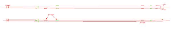
Here is the redrawn boom. The boom itself is not changed, but some of the fittings are. The changes are in green:
- I added a band for the main sheet
- Four cheek blocks for the lazyjack rigging
- Removed one of the 10” cleats
- Moved a pair of 10” cleats a few inches, per the book text
- Moved the boom haul eyelet a couple inches
- Moved the topping lift sheave from the side of the mast, to the center.
I did well on the rest of it. The lazyjack cheek blocks may become eyelets on the model, they are very small.
The book had a diagram of the masthead fittings. I scanned it in and scaled it as close as I could get to the book plans.
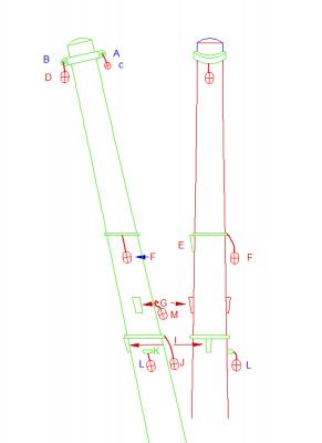
The letters are from references in the text in the book detailing the rigging, line by line. I still have to add the lower mast fittings, but that will be quick there is only 3 or so, I just ran out of steam today.
I’m a little down today, as we got a call from my stepdaughter that her home burned down last night, with her 2 dogs and 2 of her 3 cats inside. One cat was outside, because it did not come in to eat, and the neighbors were able to rescue her parrot, who was on the porch. Doing the drawing changes helped get my mind off it.
-
-
-
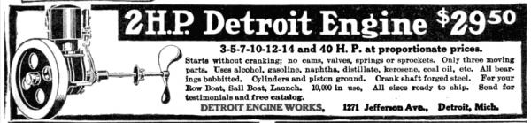
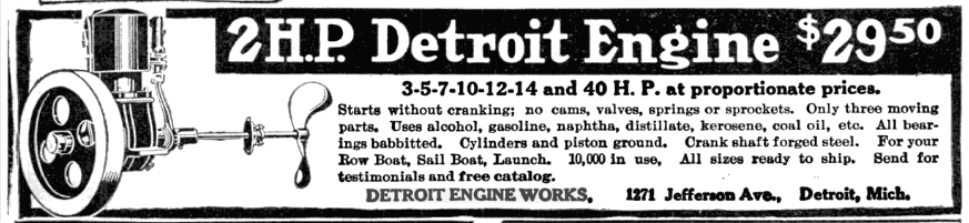
$29.50 sounds good, until I found out the average yearly income was around $400. So that's about $2500 to 3000 today. I'll take a couple myself though.
-
Part 17 B
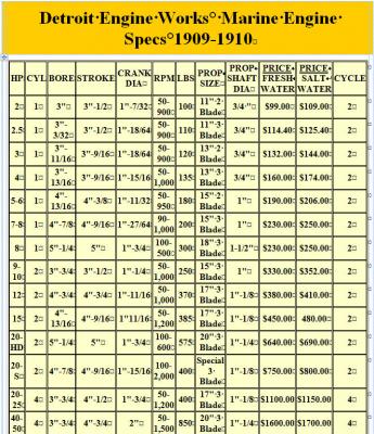
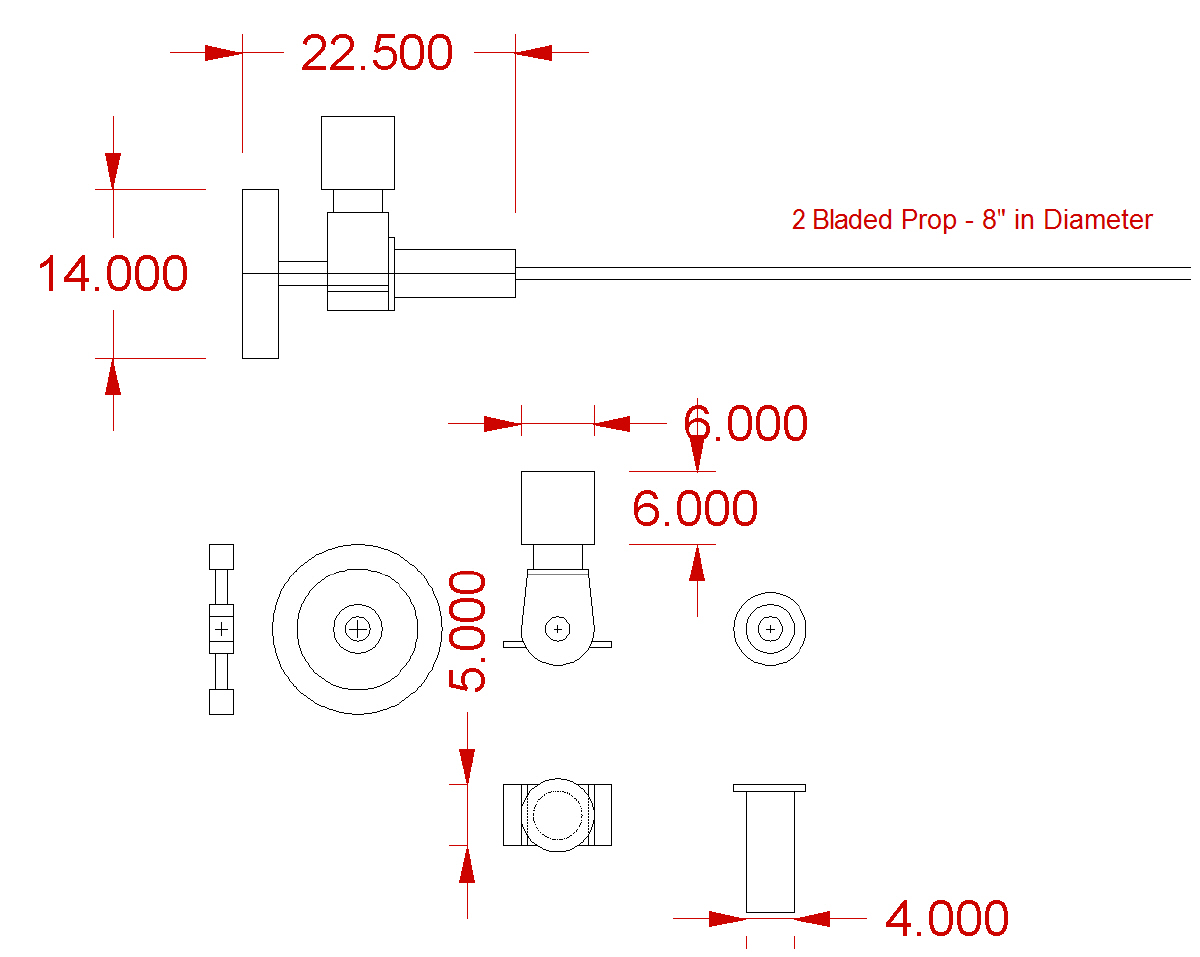
The smaller engines were all similar in size, based on the bore, stroke, and prop size. I based the engine I drew on the Detroit add for the 2 HP engine. I thought that is squarish crank block and side located engine mounts looked more “engineish” than the Kowalski’s spherical crank block and circular bottom mounts.
Also most of the base of the engine will be either hidden, or not modeled. As it turns out, due to the way the kit hull is cast, the bottom of the engine and flywheel will be not modeled, or will be cut off afterward.
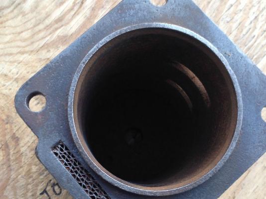
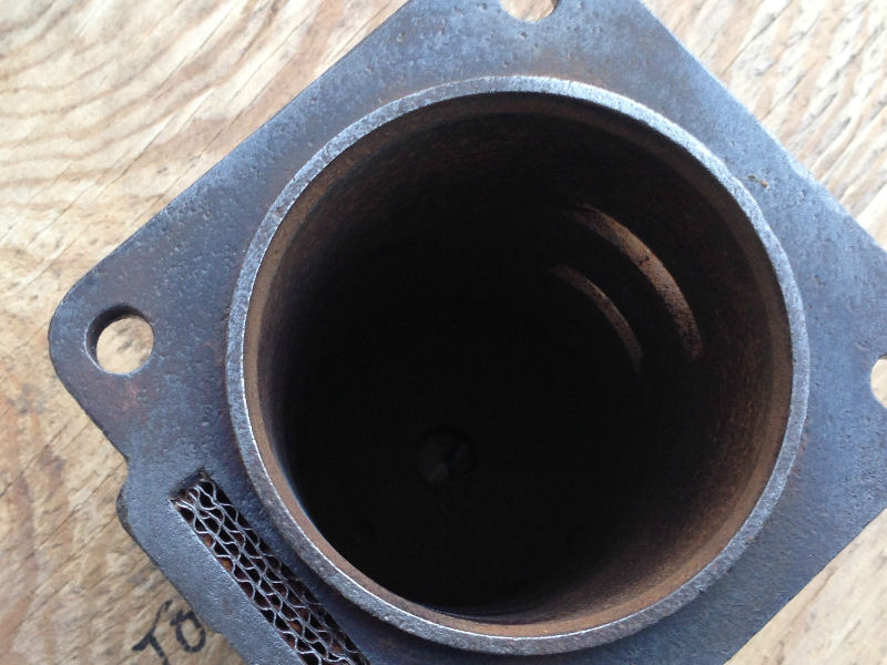
To get a basis for the size of the engine, the only reference I had was the bore and the overall diameter of the outside of the cylinder block below the water jacket. I found a cylinder block for a period engine with a 3 ½” bore on EBay. The pictures allowed me to determine the cylinder wall thickness to be bout ¼”, giving me a 4” diameter on the outside of the bore.
I scanned the Detroit 2 HP add into my CAD program, and set the width of the bore sleeve to 4”. I did the same of the Kowalski engine. After using the CAD program to dimension the other parts, I drew my own engine, using those proportions.

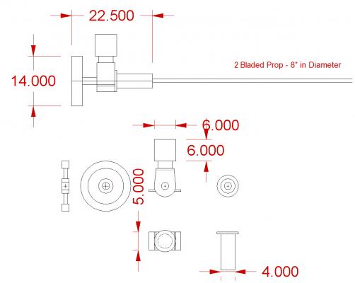
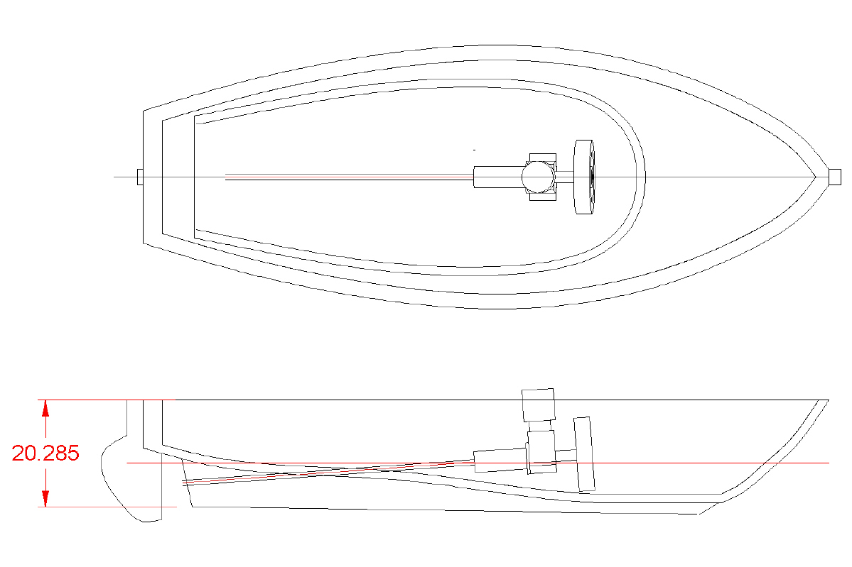
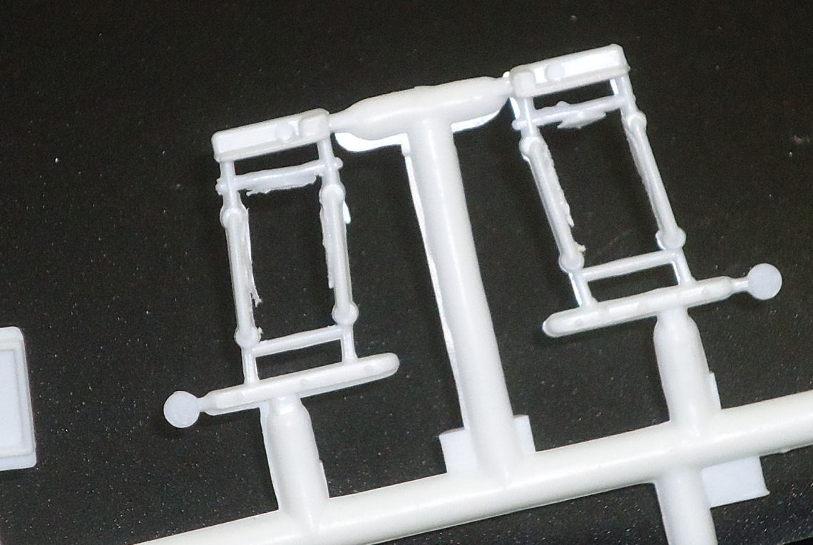
I scanned the kit parts and made a drawing of them. This allowed me to see if my engine would fit, how it looked, and a realistic position for it in the model.
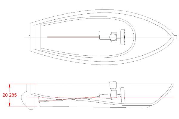
After finishing the drawing, I then looked a bit closer at the kit hull. I had assumed that the hull was about the same cast thickness. I was wrong. I had failed to notice that the slat flooring inside was cast as a flat surface (the red horizontal line). This is why I mentioned earlier that I will not model the bottom of the engine.
I printed out the engine on paper to scale, and glued the top and side views into a 3D pattern.
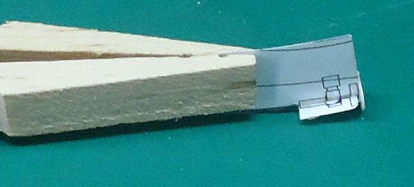
Yes, that is the end of a reversed clothespin holding the tab of the scale pattern! Like I said, superdetailing the engine model would be a near miraculous task!
I placed the pattern into the hull to see how it would look.
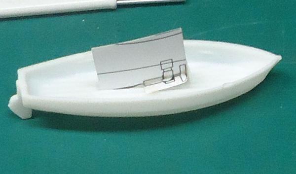
This satisfied me that it would fit.
I also found some pictures of a similar Detroit engine installed in a period 18’ launch.

As well as a picture of the same size launch from a factory add.

Ok. How I will go from here. The Leonard model photo shows flooring at the level of the engine mounts. I will carve out the kit hull flooring to the outline of the model engine, plus a little. I will build the engine, and make a simple prop. I Will Not obsess about the engine being in perfect line with the prop center.
My truck died 2 weeks ago, far from home, rather fatally . I have been feverishly working on getting our car running, and the next installment may be a week or so.
-
Part 17 A
The ship’s boat could be built one of three ways. Just use the stock parts, this would represent a modern push boat, with a big engine.
I could scratch build an oar powered skiff (really small work).
I decided to go with an intermediate type, inboard powered, but using an one cylinder engine of around 1900. This would use most of the stock parts, but remove the seats and engine box. I would install a little exposed single cylinder engine (or at least something that looks close). This type and the oar powered skiff, are closer to the period I’m modeling, when she was built in 1895, and used hand cranked dredges. In this case the boat is used only for transportation, not pushing.
The traditional modern Push Boat I’ve talked about previously, but will detail some more.
I was not completely correct about its use before. At that time I said that it was used for pushing the boat while dredging in light or no winds. While this is correct, after more research I found some restrictions that have changed over time.
- Before the 1960s, the boat could only be used to get the skipjack to and from the oyster beds, but not used during dredging.
- In the 60s this was changed to allow its used while dredging, but only two days a week. It was further restricted in that the two days were specified as Mondays and Tuesdays. Monday and Tuesday were the only days allowed until the 1990s.
- In the 90s, the law was changed in that, while they could still only dredge two days a week, the crew could pick any two days each week. This allowed for changes in wind and weather during the season.
- When not in use the boat had to be stored in the davits, so that law enforcement could easily see that it was not being used. They, of course, kept a watchful eye on the dredging operations. In recent times by plane, to cover a larger area.
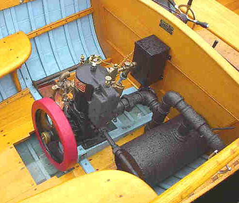
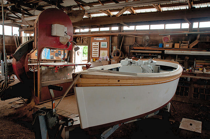
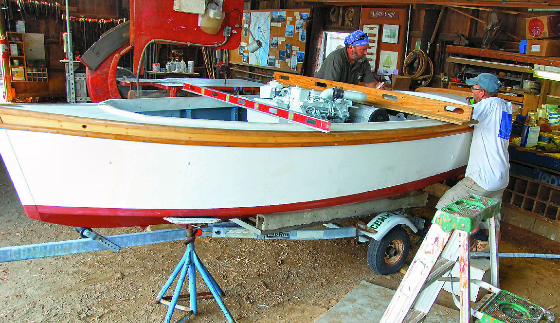
These pictures are of a modern Pushboat for the skipjack Rosie Parks. This is during its recent restoration. The Rosie Parks is a restored skipjack at a the Chesapeake Bay Maritime Museum.
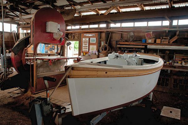
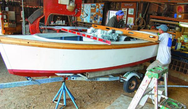
The engines in these are huge, compared to the hull. This one is a turbocharged diesel. Note also that, the man on the left seems to have been doing a lot of restoration work outside.
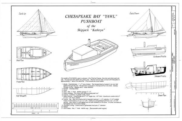
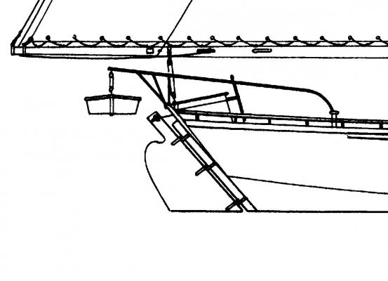
Here is a drawing of another Pushboat from the National Archives.
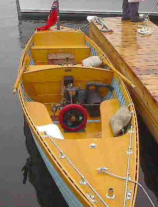
The intermediate type that I am trying to shoot for, is when small inboard gas engines were first being used.
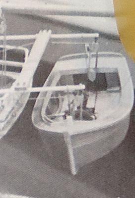
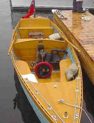
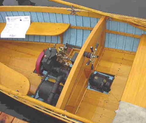
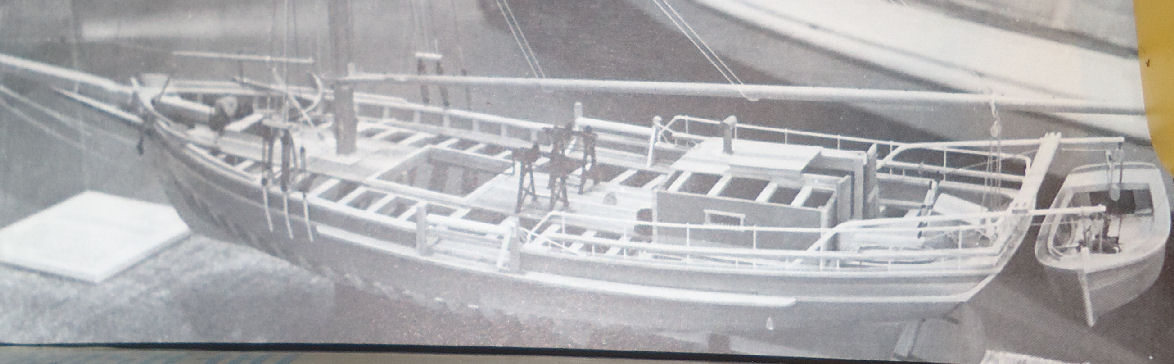
You can see a small marine engine in this picture. The most visible clue is the large flywheel. There are no seats, and it looks like there is a tiller and thus a rudder.
This boat is on a model of the J T Leonard, an Oyster Sloop. These were the immediate predecessors to the skipjacks, built from about the 1840s until the 1890s, when the skipjacks took over.
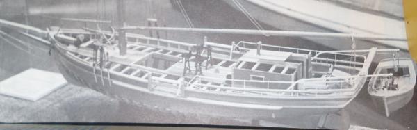
This is the full model. While these had a similar deck arrangement, they were built in the traditional framed hull method, with a rounded hull form. As you can see she still had the hand cranked dredges, when her boat had the old type engine. She was formally at the same museum as the Rosie Parks, but no longer exists. She was acquired when the museum first opened in the 60s, and at that time funds were short. By the time enough funds were available, she was too far gone to save. This is a model at the museum.
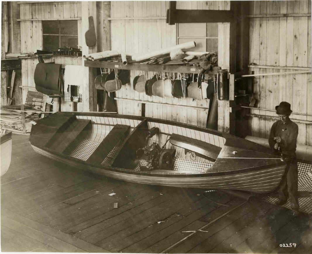
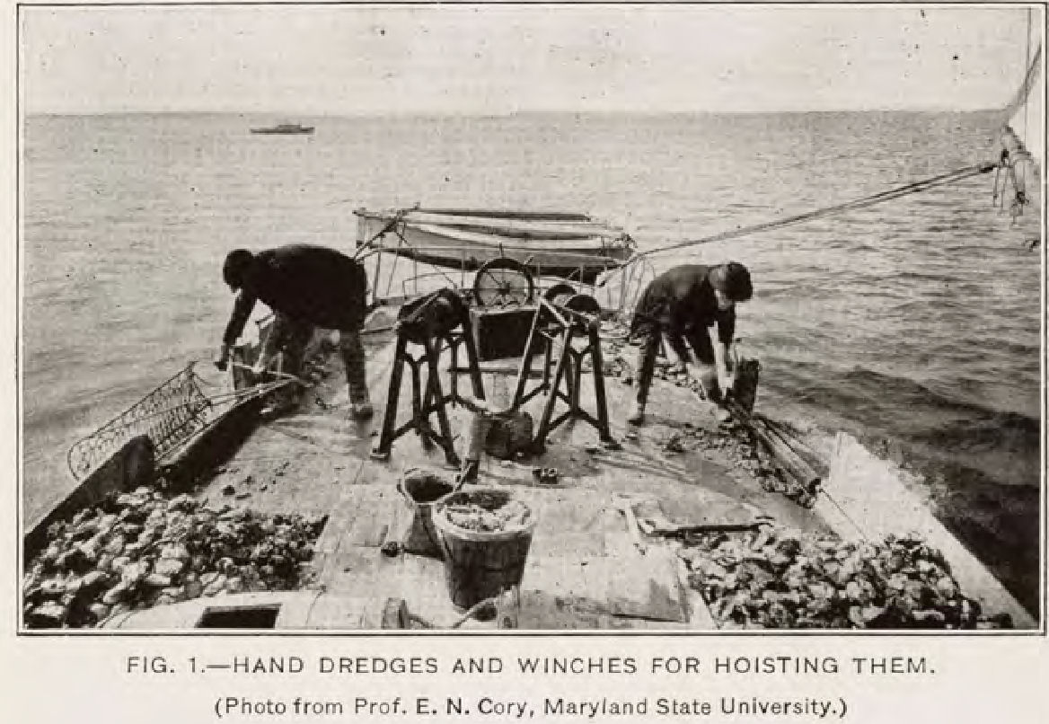
The original ship’s boats were oar driven. Flat bottomed skiffs being popular. This is the kind shown in the photograph below. This is one of the pictures used in the hand dredge post.
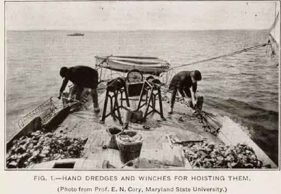
The drawing for the Carrie Price shows this type.
I did not want to scratch build a skiff, and the supplied parts in the kit are for a modern Pushboat. The hull of the kit parts does, however, resemble that for the one on the J T Leonard model. So I decided to scratch build an engine, and modify the kit boat.
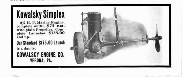
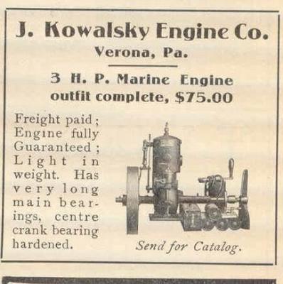
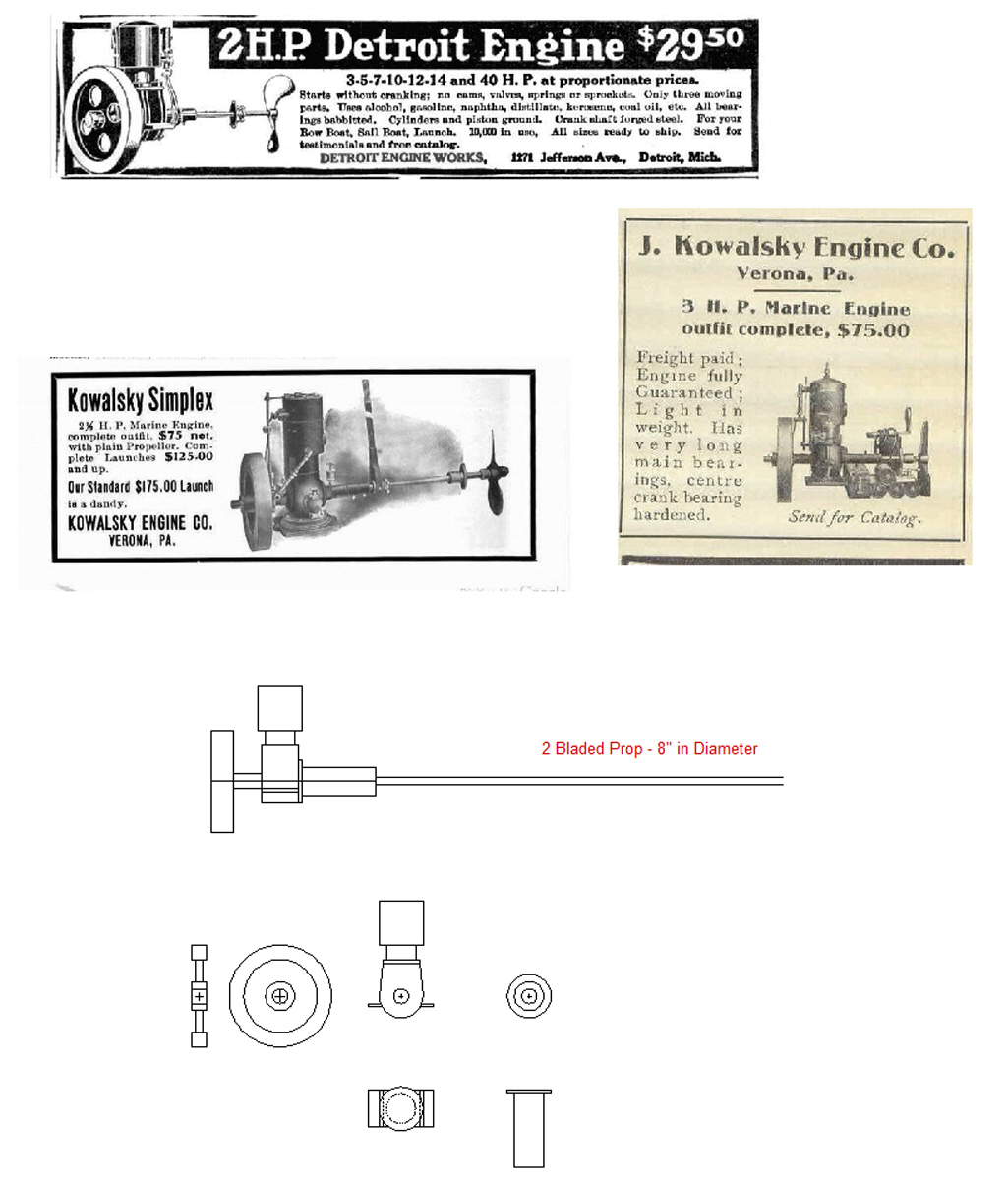
I researched early inboard gas engines of around 1900, and found a wealth of information on the internet. What follows are some of the pictures and advertisements I found, for engines about the right size.
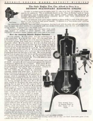
As you can see, the engines and transmissions are not complex. In this small scale, I plan to leave out most of the small details, and just build the basic flywheel, engine, and transmission housings. The engine will also be mostly hidden by the deck and combing, and my model is of the skipjack not its boat. Superdetailing the ship’s boat would draw the eye to it, not the larger model. The fact that superdetailing the engine and Pushboat would probably take as long as the rest of the model (and drive me insane), never crossed my mind. J
After consideration I decided to go with a Detroit type motor, with a lever for the transmission like the one on the Kowalski engine.
I measured the space available between the kit boat’s stem and rudder, and the largest prop I could fit was about 8” in diameter. From the chart below, that puts an engine in the 2 to 4 HP range as scale. I think for a 12’ boat, this would be right for the era.
-
-
Part 16
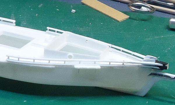
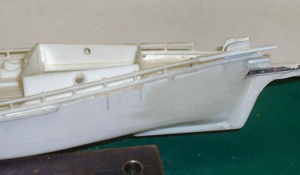
The transom on the model is notched where the rails end. On the plans the transom goes up “straight" and the rail ends butt to it.
It took leftover pieces from the railing stock and glued then in the notches, after cleaning them up a little bit. The pieces were larger than the notch on all sides.
After letting the glue dry for several hours, I filed the plastic to be flat with the front and back of transom, and with the edges of the transom in line with the hull.
A couple notes on this:
- I used the “Fingernail Test” to determine when the new parts were flush with the old. This involves running your finger nail along the seam. If it slides past the seam without catching, the seam is flush. Machinists used this test on their parts.
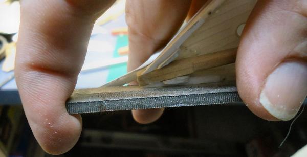
- Look at your files, some of the flat ones will have a “Safe Edge”. There is one thin side with no teeth. This allows you to have this edge against a surface that you do not want to remove. I had the safe edge against the top of the railings. Not all files have this, so check yours.
The next order of business, was the chain plates. The kit had a couple problems with these. The chain plates, deadeyes, and shroud lashings were all cast as one piece. To use them as is safely I would have had to attach them after I painted the hull, and was installing the spars and rigging. I would rather paint the chain plates with the hull.
Hole in hull where chainplates attach.
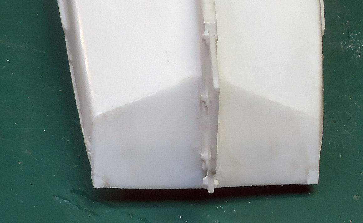
The kit parts also had a bar between the chains at the bottom, and a coil of rope suspended between the shroud lashings (see the left hand red circle on the box art, below). If you look at the second red circle, you can see there was a similar rope coil on the railings, I removed this too. The rod was not shown on my plans for either this boat, nor the Willie Bennett. A circular coil of rope is not something you would find on a real boat, that is not how real rope hangs.

A couple months ago I carefully used a razor saw and knife to remove the coil. I decided to cut the chain plates free and, if I decide (likely) to use the rest later, I will remove the lower bar, and thin the upper. While the shroud lashings are crude, I don’t think I could do any better with real scale deadeyes and thread. The running light boards are also attached the these parts, making keeping them more attractive. I may scrape groves in the cast lashings with a knife to make them look more like separate lines.

After I cut the chain plates free I removed most of the casting lines. I left a little to represent the line between the part attached to the hull, and the cap bolted to it to lock in the deadeye straps.
I drilled shallow holes in the tops of the chain plates where the cast straps had attached, to mark their locations, only to find that stock positions of these joints did not match the locations of the straps cast on the hull. I’ll fill them later.
I glued the chain plates onto the hull.
I've been researching the Skipjack Push Boats a little more, and will be talking about them next time.
- GuntherMT, captainbob, Mahuna and 1 other
-
 4
4
-
I don't have TurboCAD, but have a couple others. Look at the options when you bring up the Print window. Is there an option to change the scale ratio of the printout?. DesignCAD has a couple of them. Maybe the default margins, or the paper size options are wrong. I hope this helps.
-
-
-
Part 2
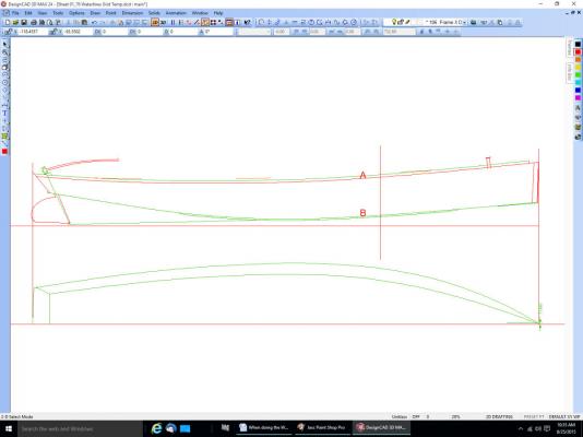
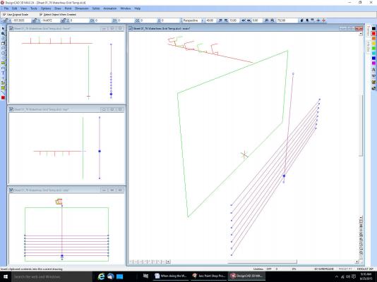
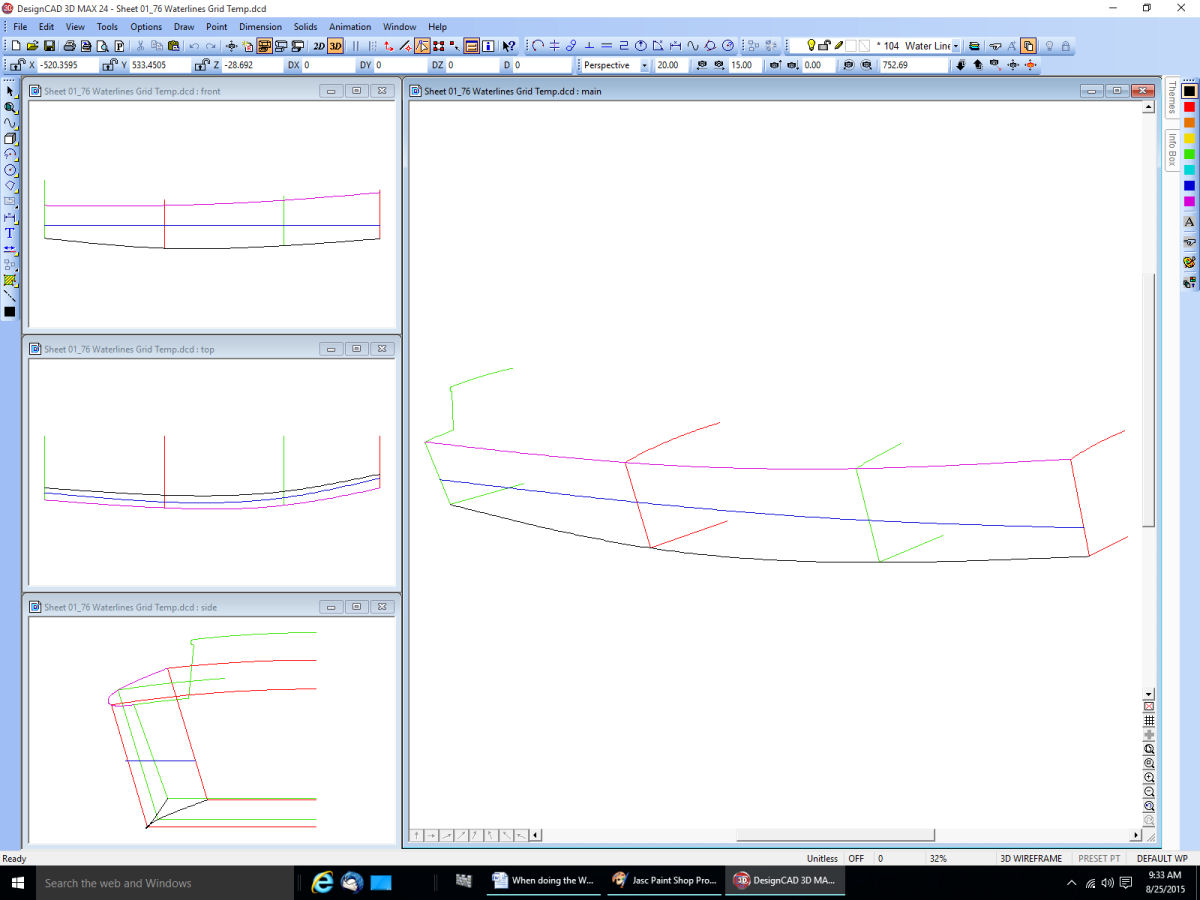
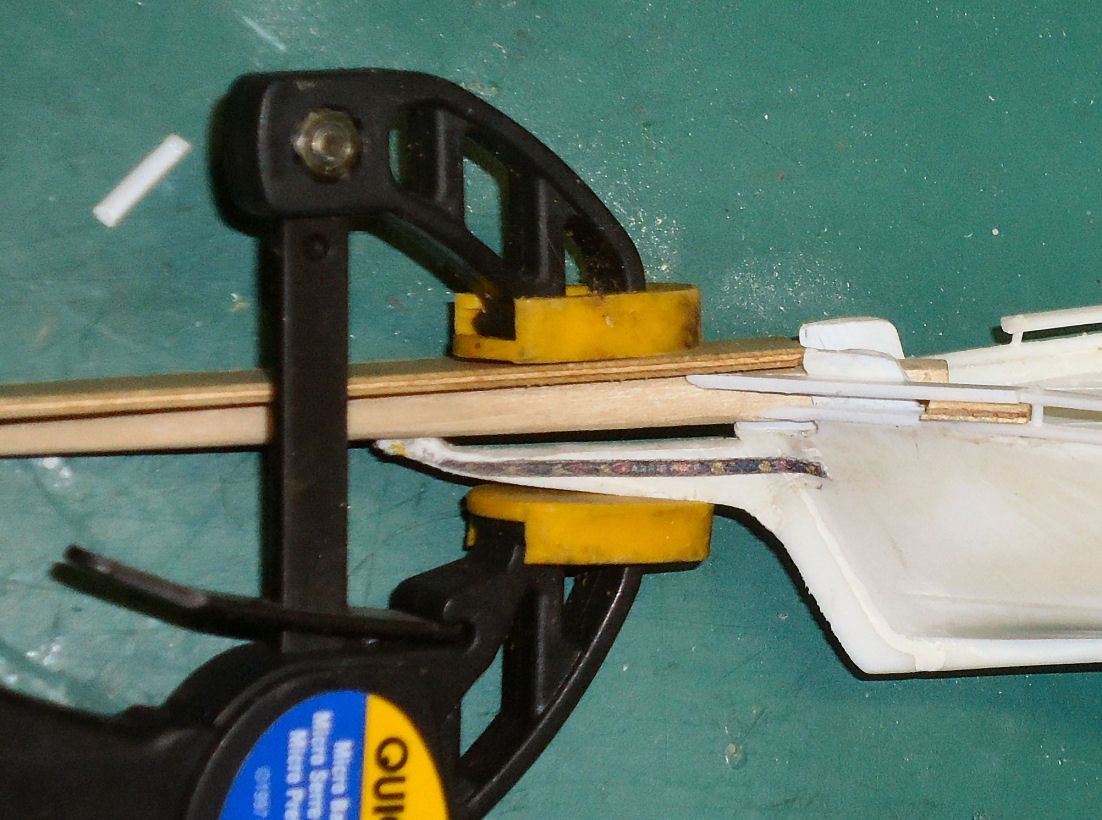
Without the all the other lines here are the shear, chine, and new waterline.
Now copy a grid to the new frame location.
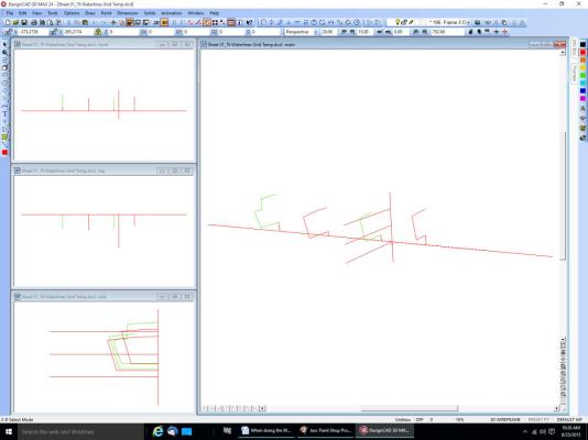
To generate the new frame you draw a curve to the intersections of the new frame grid and the waterlines.
Here in lies the rub. Notice that the shear and chine lines do not fall on a grid line. I have never been able to figure out how to draw the curve to these points, as there is no intersection with the grid. I’ve tried locking the Z axis, drawing a perpendicular to the reference lines, etc. The program always chooses the point on the line closest to the cursor. You cannot place the cursor at the right spot, that is what you are trying to find for the new frame.
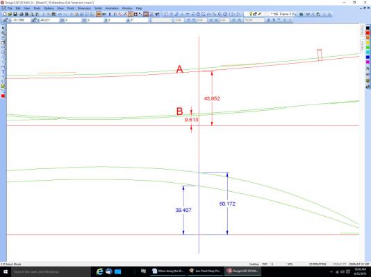
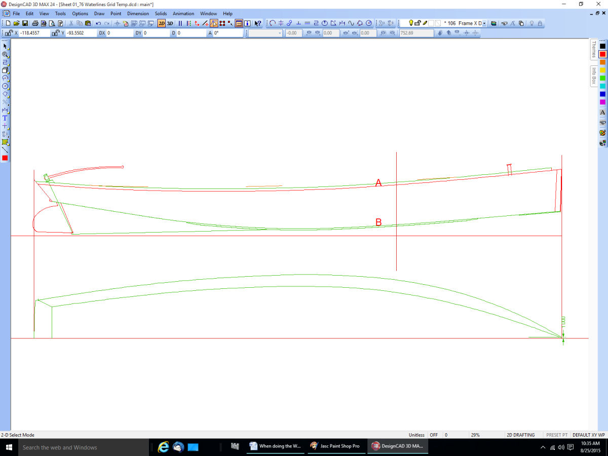
The only way I have found to do this is to go back to the 2D side and deck views I drew previously along with the frames. I always draw these first from the drawing or Offset Table. Then I turn on the layer with the new frame grid, and draw a line top to bottom on the 2D layer.
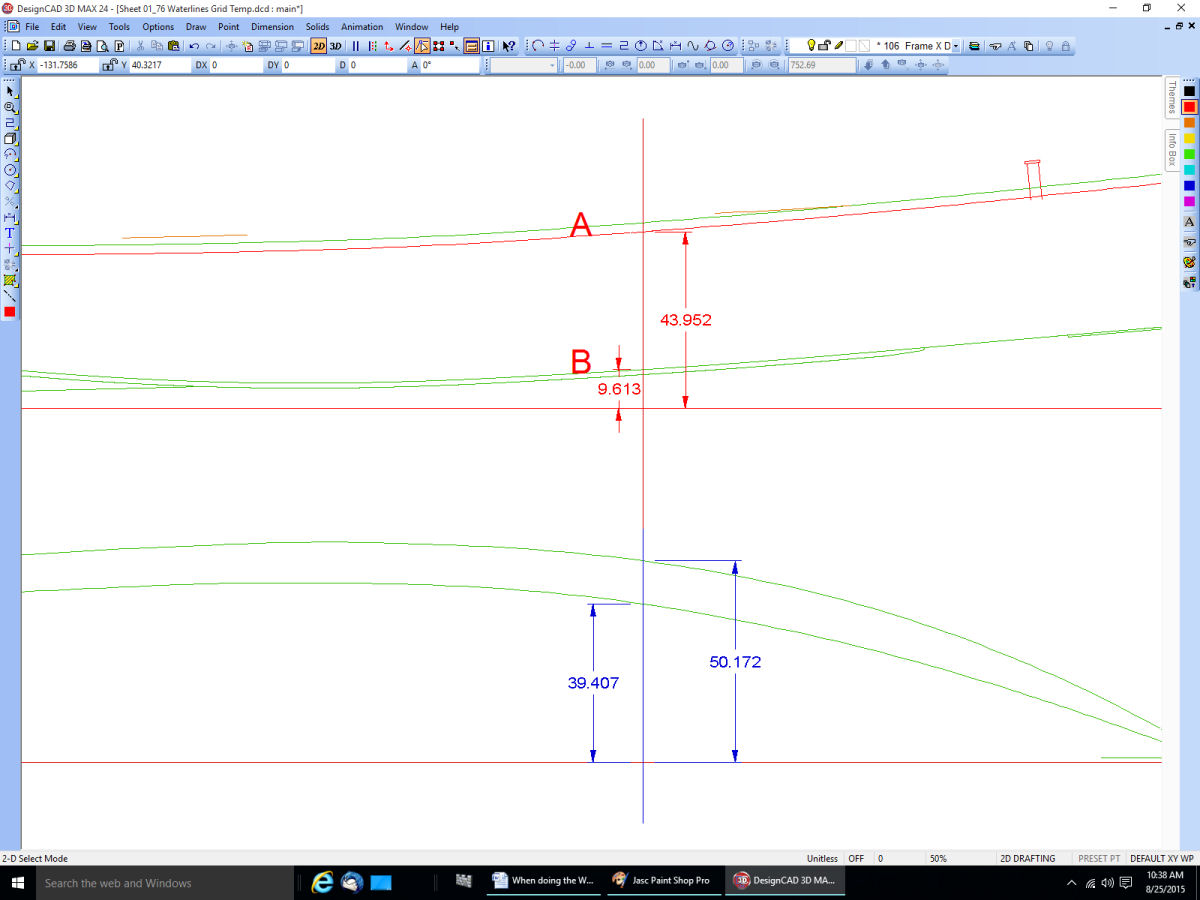
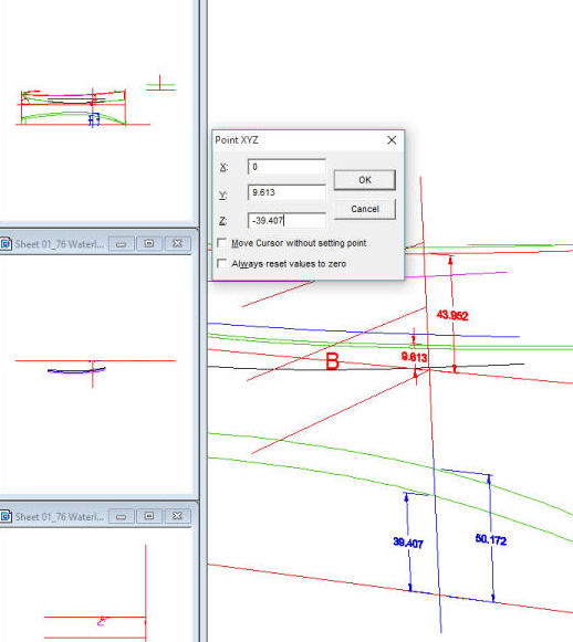
Then I dimension the intersection points I need. For a drawing with curved frames, you would still need to find the shear and point where the planking meets the keel. This is a pain! If someone knows how to do this, please tell us.
With these points found I go back to the 3D view.
I use the Point XYZ command “:” And enter the first point.
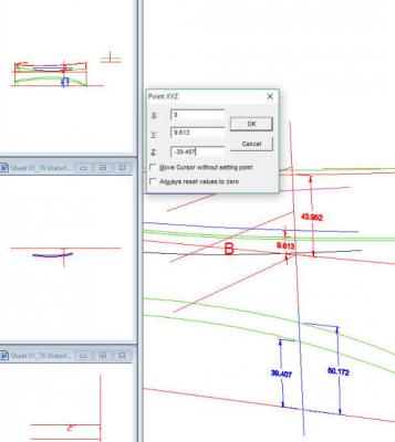
Then I select the intersections of the grid and waterlines. In this case only one.
Then use the point command again for the other end of the line.
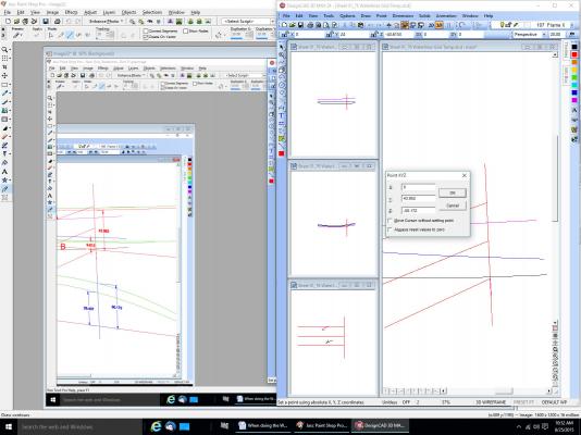
This completes the first new frame (green line).
I hope this helps. It would have been better with curved frames, but I don’t have any drawings with those, yet. I’m doing one for the next boat. Fortunately it has a straight keel to planking line, and the keel is not tapered along its length.
Another way to do it is before you go to 3D and place the frames, draw a grid on each frame layer. This does clutter up the frame drawings for other purposes though. It can also make setting the frames in 3D difficult, with all those lines.
-
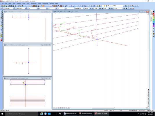
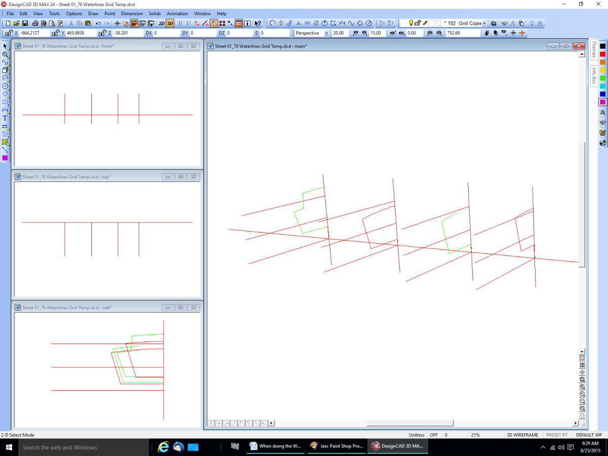
Part 1
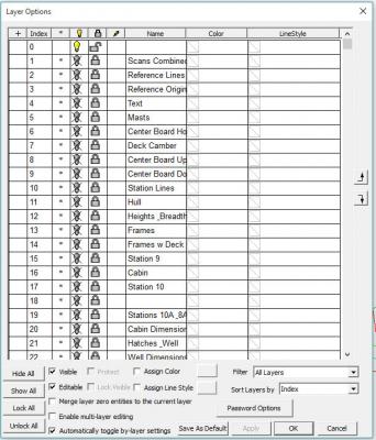
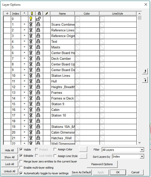
When doing the Waterlines, use a different layer for them, like you did for the individual frames. Not everything has to be on layer 0. I use many layers in my drawings, sometimes for subassemblies, like a frame, or even individual parts (tiller, mast, centerboard and housing, etc.). On my Terrapin Smack I have two layers for the centerboard, one in the up position, one in the down. At the present time I have somewhere around 40 layers. I sometimes have several layers for a “thing” as I progress in drawing it, just in case I make a mistake, I can go back to the previous layer, much as using the Save As command.
Sometimes I do this if I am not sure of the part/section I’m drawing. I may not completely understand a part of the drawing, or it might not be clear which line of a detail area is part of the detail, or just a line overlapping from another.
For example I have multiple layers for the trailboard graphic on my skipjack drawing. One for the outline, another for the eagle head craving, etc. I turn on as many layers as I need as I go. When I was done with the initial design, I later made new layers with changes I felt would make it look better. This way I could easily select from any of the layers to compare old and new. If I decided for example that a line in the carving design needed to be different, I could change it, then switch between the layers, or turn them both on at the same time to compare old and new. Much easier than looking at different versions of different drawings.
As of my latest Smack drawing I am at version 76. Sometimes I have to go back a version or two and restart from there because I made an error that is easier to correct by redrawing from that version, than trying to correct the one I am on. Typically I deleted something I should not have, or really messed up a section I have been working on. If I’m on version 50 for example I might go back to 49, correct the error, then save this as version 50, overwriting the mistake. I might also go back to an earlier version, and just copy something from it to the latest version, if I deleted something I should not have, perhaps I even deleted it a couple versions back, and do not want to lose the additional details I have drawn since then. I generally save a new version after any major change, or several times a day, if I’m still on the same part.
As in making the model itself, sometimes you break a part off ,and have to replace it, or decide you can make it better than the first time.
Now onto your question.
Now that you have your frames, you can go a couple routes. The easiest one will involve some more drawing, but be clearer on your final drawing.
One thing to remember is that you can move the origin (0,0,0) to anywhere on the drawing with the Point – Origin command.
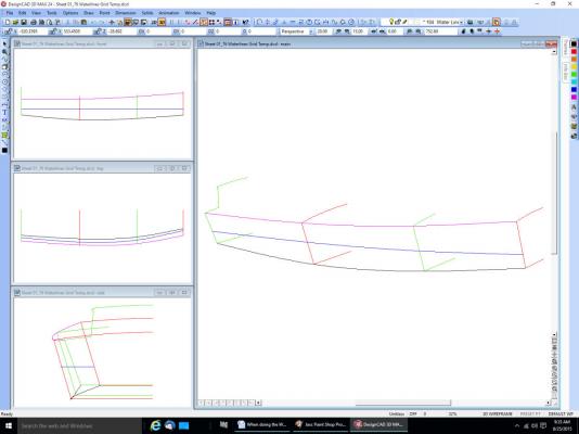
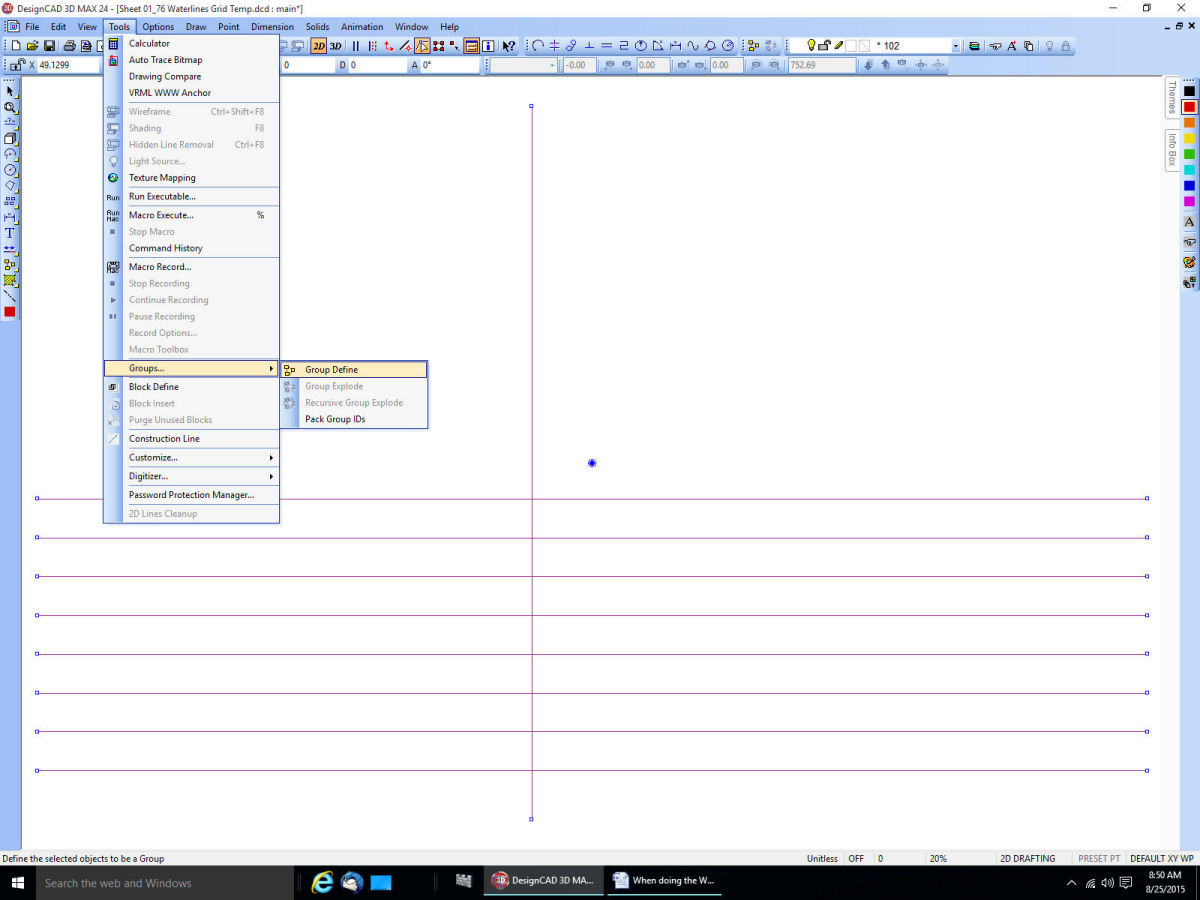
Create a new layer, call it for example “Water Line Grids”. Switch to 2D mode. Draw Your waterline grid, using whatever spacing you want. Then select all the lines and make them a Group.
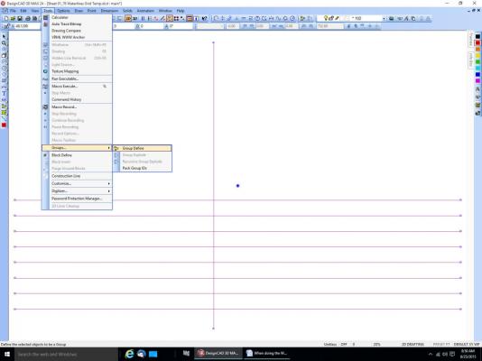
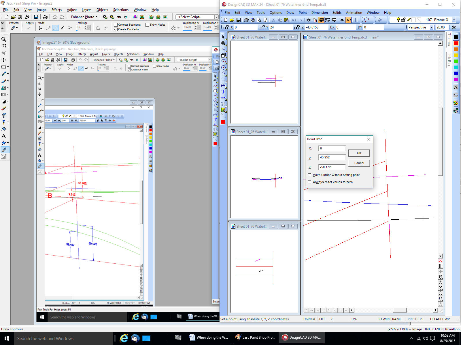
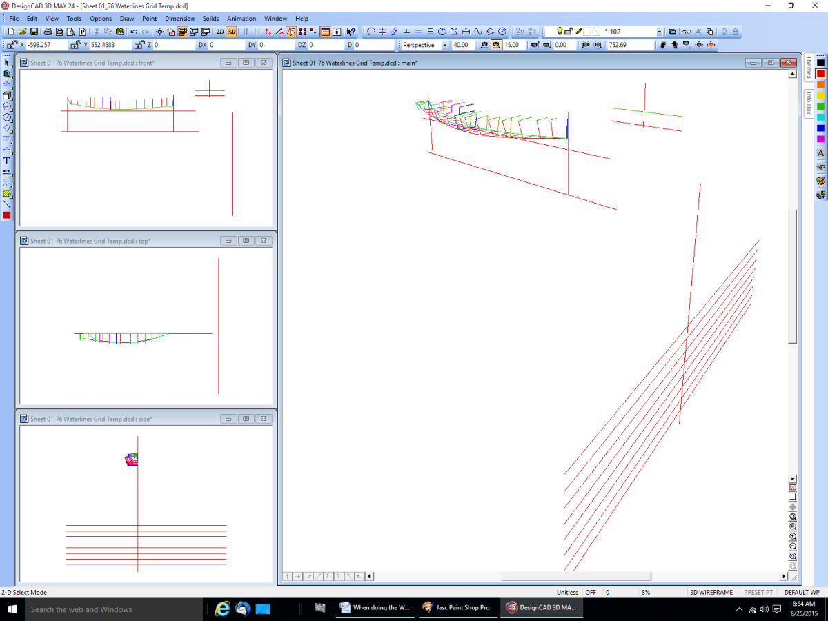
Select where the baselines cross. Go back to 3D, then rotate the grid 90 deg. Around the Y axis. It will look something like this.
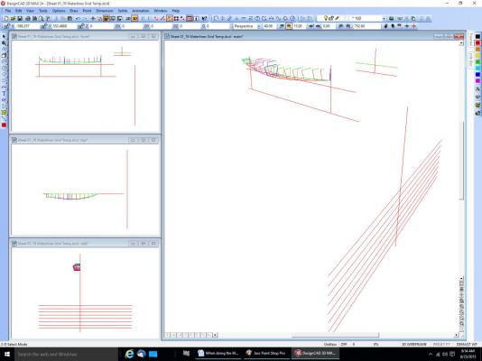
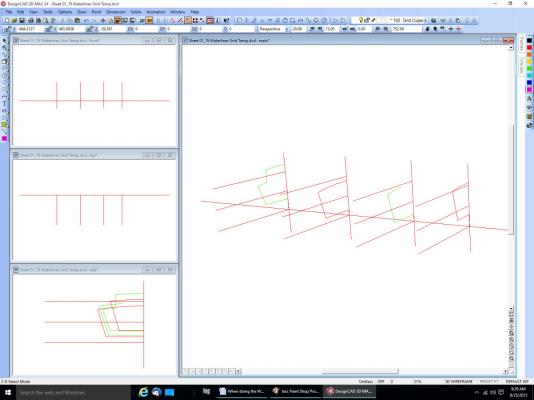
Here’s a view with some of the frames removed for simplification.
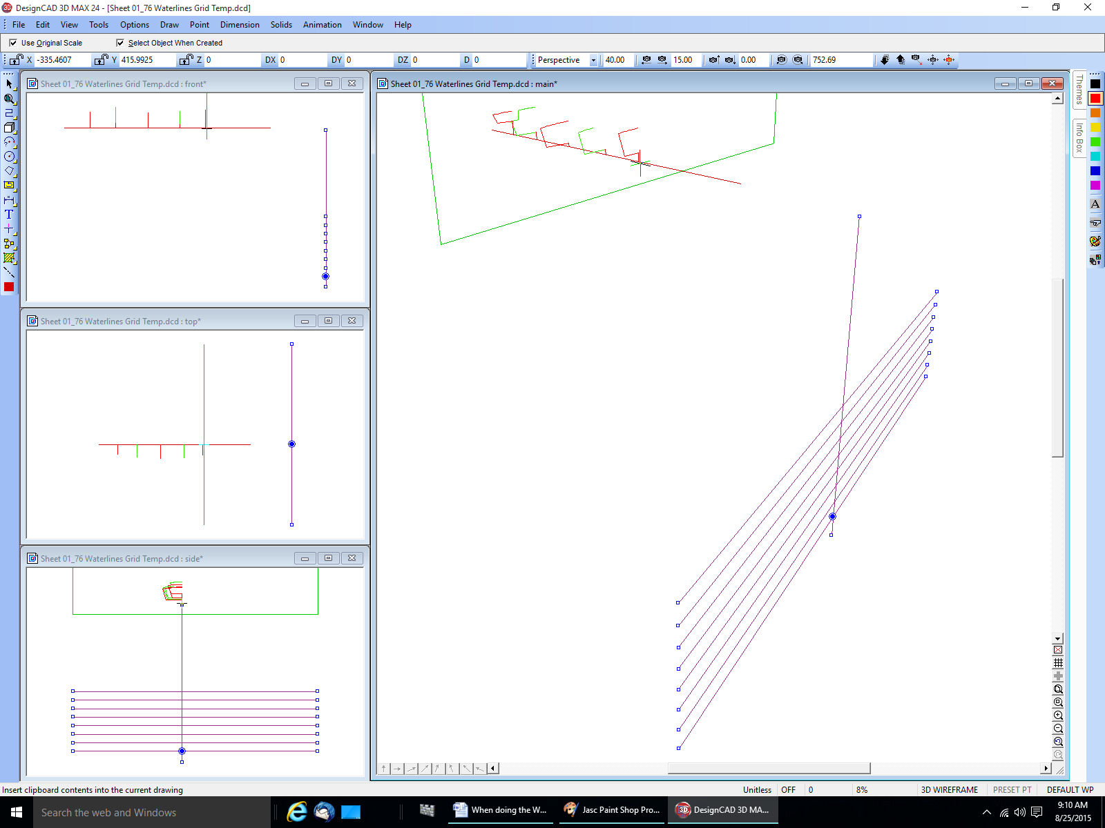
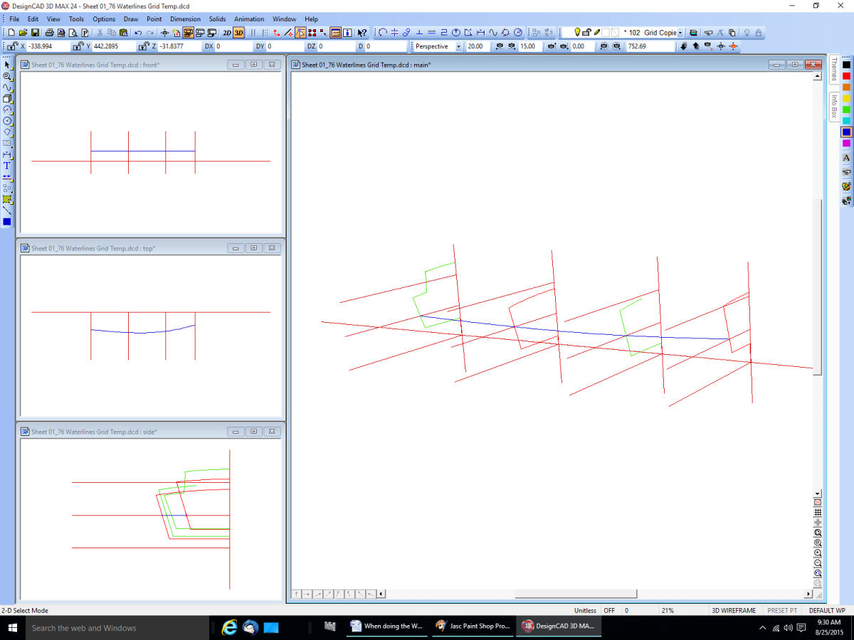
Now select the intersection of the grid and baseline again.
Copy the grid “Ctrl C” and then paste it “Ctrl V”. You will see an outline of the group that will move with the cursor.
Go to the intersection of the first frame and the baseline and select it “F4”. The copy will drop to this intersection point, and you have your first waterline grid placed.
One important note about the F4/intersection point command. If you have 2 or more lines laying on top of each other, the program can not figure out which of the overlapping lines you mean, and will fail. For instance in this drawing, if I copied the baseline from another layer, or redrew it for some reason, and had both layers on, the command would not work. I would either have to turn off the original layer the line came from, or erase the line on one of the layers. This one gets me all the time, expecialy in 3D where lines can be on top of each other in one of the views.
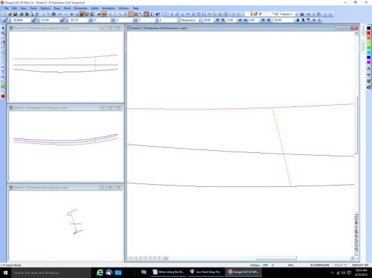
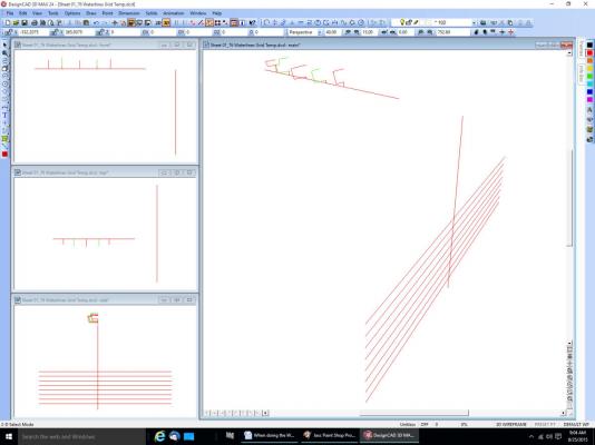
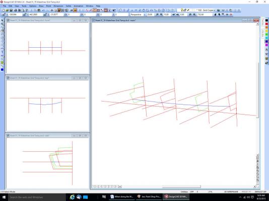
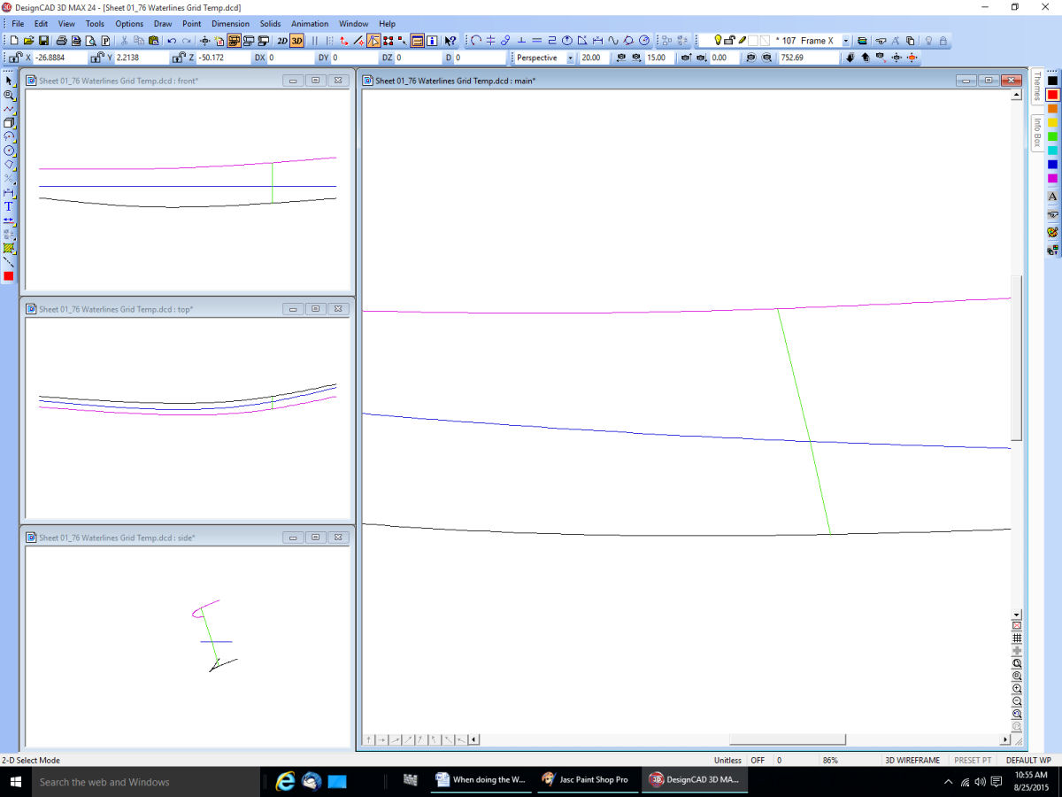
From here on I simplified the grid and removed some of the frames, to make it easier to see what is going on.
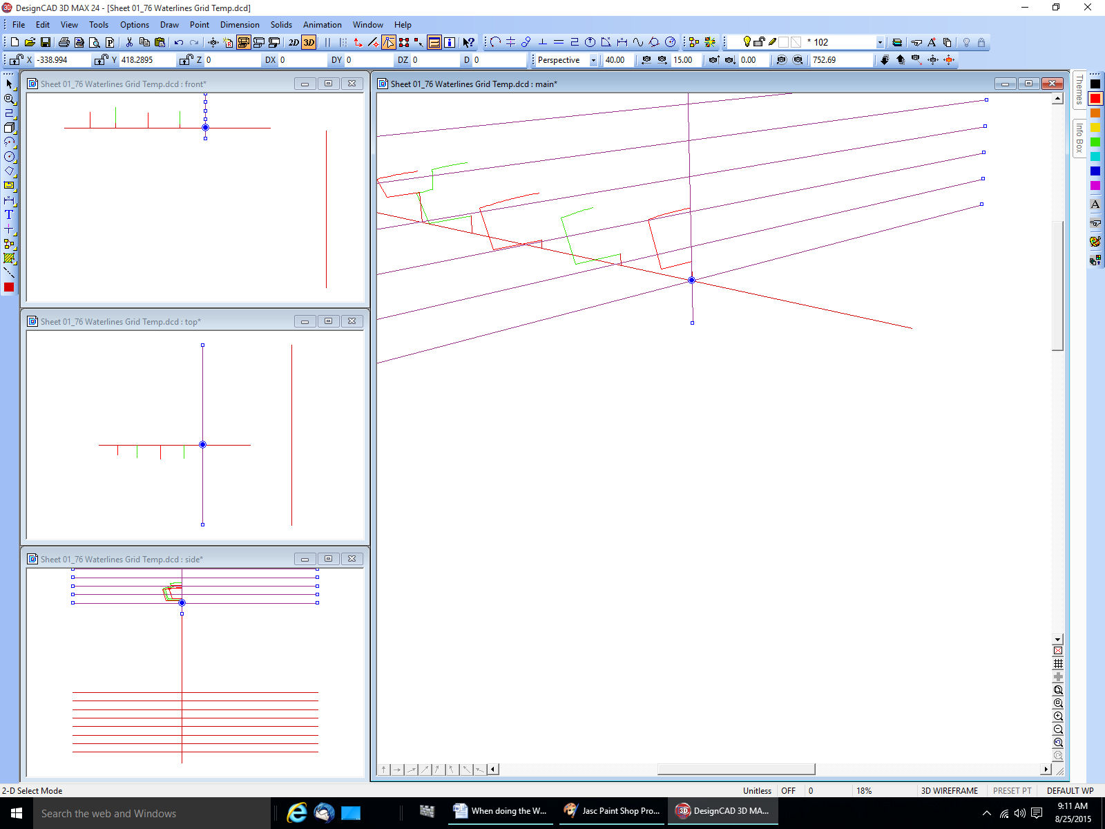
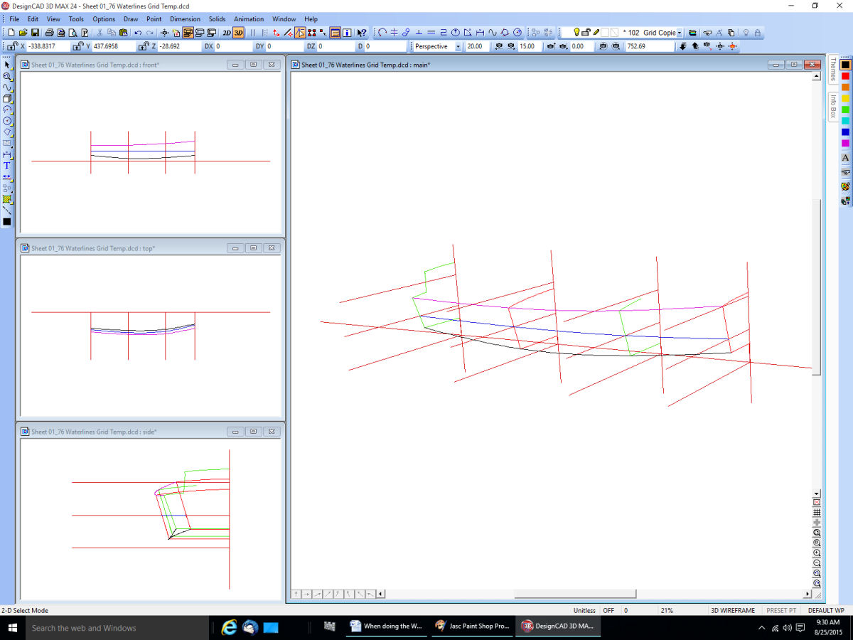
I copied the other grids in.
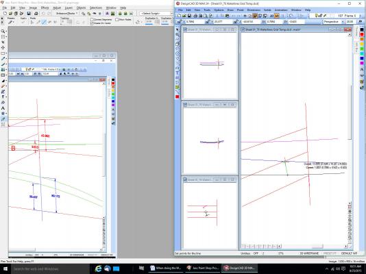
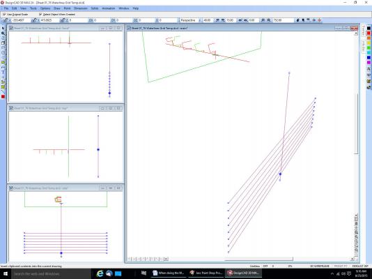
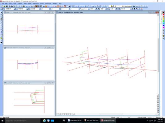
Using the Draw – Lines – Curve Connect the intersections of a waterline and the grids. The blue line below.
Next I connected the shear and chine points.
- mtaylor and michael mott
-
2
-
Part 15
I started on the fore upper rails next.

I clamped a block at the top of the bowsprit, where the railings would meet it. This is a little high per the plans, but the kit railings are high. In fact the new sections dip a little between the old rail and the bowsprit. Maybe no one will notice. I also placed a block between the lower rail and the new piece. I glued on the port extension first.
The starboard rail extension followed.
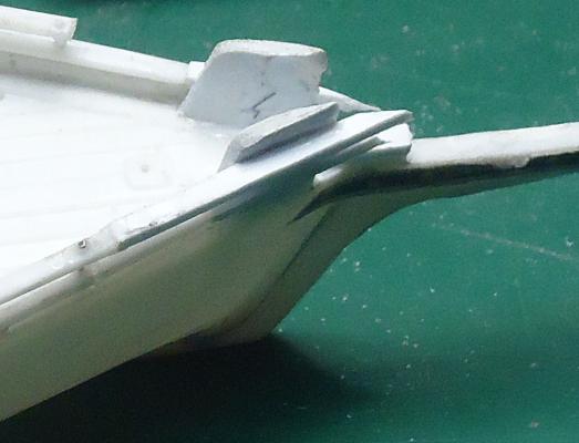
Then I trimmed the starboard rail, and found a problem.

It’s hard to see in the photograph, but when the new section was sanded to match the old, there was a kink right at the joint. The old railing tilted inward about a ¼ of its width. It was much more visible when looking at the ship from above the bow. As this was right in the area that you would first see when viewing the model, I decided to correct both rails before continuing.
I would need to cut some stanchions and move the old section outward. This involved what I have been trying to avoid, drilling a small hole in a small part.
I removed the first stanchion and cut loose the bottoms of the next two, and cut off the bump at the top of the rail that represents the top of the stanchion rod, where the head of the rod/bolt is. I also broke the joint between the old and new sections.
I used a piece of wood clamped to the deck to push the old rail end outward, and stuck a 1/16” piece of plywood between the upper and lower rails to support the upper rail during drilling. Then I drilled through the upper rail in the former location of the bump, with a #76 drill (about .020” in diameter, the railing was .060” wide). Once I had the hole through the upper rail, I removed the ply block and drilled the lower rail, also in the center, sort of. When I was done I found that the drill bit had wondered and cut down the outside of the lower rail, rather than the center. So I drilled a second hole a little further back.
The second hole was a little off at the top rail, but spot on for the bottom. I decided that it was good enough.
I used a #73 drill to open the holes for the pin used for the new stanchion.
You can see the two holes at the upper right of the picture.
For this operation I used my Optivisor (with its greater magnification), and went slowly.
I inserted a pin into the upper and lower holes as the new stanchion, and secured it with thin super glue. I also used the super glue for the railing joint.
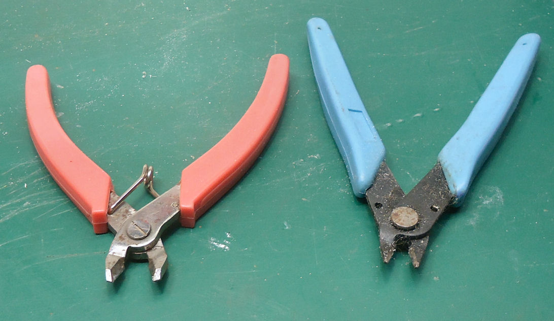
I cut the pin off with rail nippers. They are like heavy duty sprue nippers. They are used for cutting the track rail on model railroads. I then filed the protruding portion, leaving a little at the top to represent the bolt head I had trimmed off before.

On the left are the rail nippers, on the right the regular sprue nippers.
You can see that I managed to knock off the port rail extension during this process. A pain, but I would have had to break the joint between the new and old rails anyway.
A little further sanding and the rail was finished. I used thin plastic cement to reattach the bottoms of the other two stanchions I had cut earlier, they were shifted a little but still looked centered.

I repeated the process for the other rail.
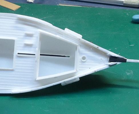
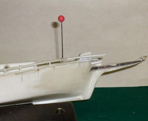
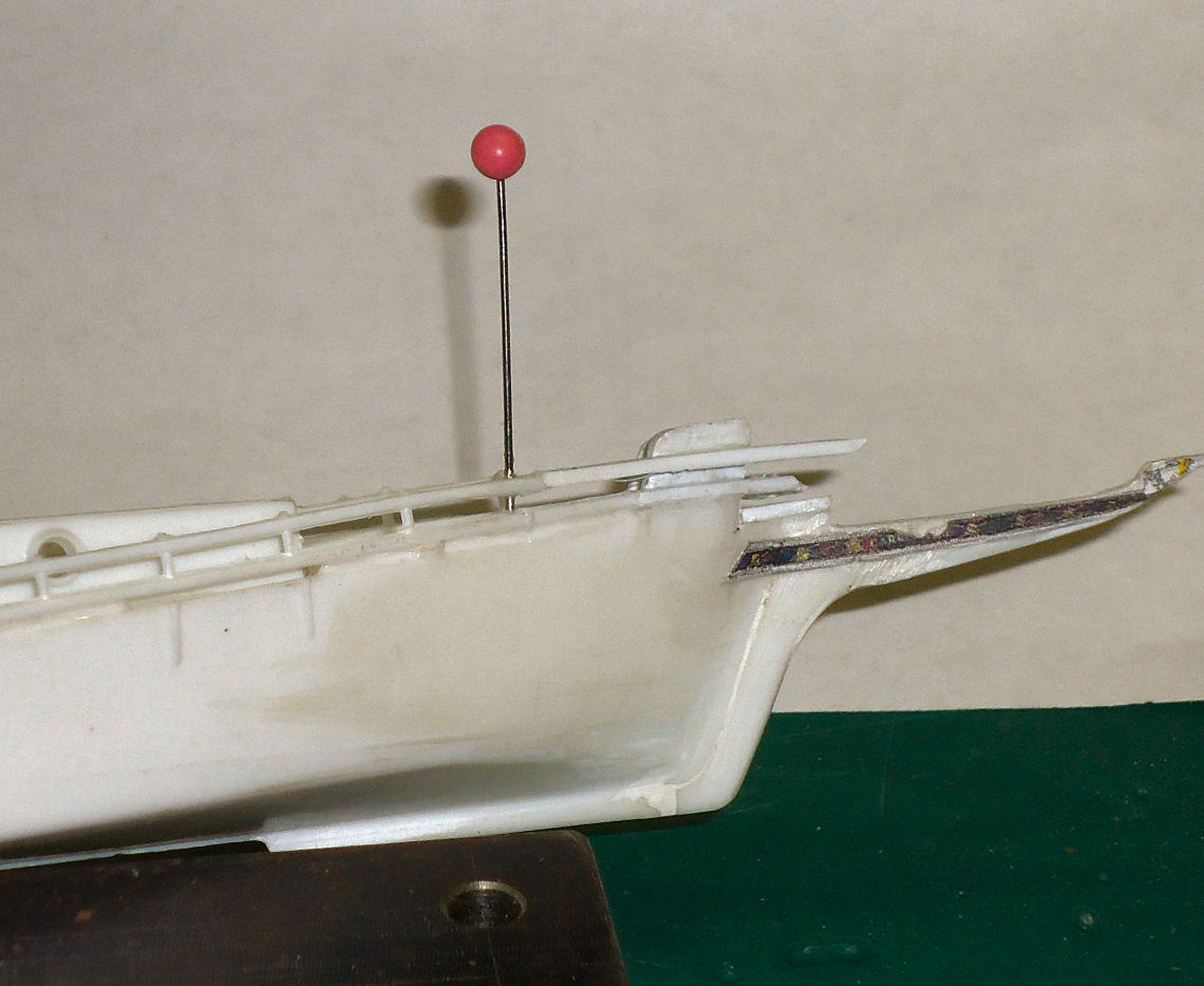
While trimming the rail I held the bowsprit, reversed, in place to reinforce the railing, and hold it in place at the tip. This is not how I held it and the file during the trimming, but I had to use my other hand to snap the picture
I used the large file to remove the bulk of the material, then switched to a needle file to finish.
After trimming the rail, I glued the stub of the incorrect bowsprit in to protect the rails while I do more work on the hull.

- Mahuna, tarbrush and captainbob
-
3
-
The Home Depot people will likely have no clue, unless there is a demo setup to show you the pretty frog or whatever that it can make.
Years ago (yes lots) when the Commodores and Radio Shack computers came out I went to RS to look at their computer. The salesmen there had NO idea what their computer did, They could not even answer questions as basic as how much memory, or the number of pixels in the resolution. Nothing even close to the info in a Commodore add.
Ended up with a Commodore 64, and over time most of the needed accessories. Made some money off it back then, I wrote a few articles on programs for it.
-
I mentioned this in another modeling forum, and they said run don't walk away. Very poor resolution for the price.
-


Carrie Price by thibaultron – Lindberg/Pyro – PLASTIC – 1:64 - Small - Skipjack
in - Kit build logs for subjects built from 1851 - 1900
Posted · Edited by thibaultron
Part 20
The next part is the mounting flange at the back of the crank case, for the transmission.
I punched out some 3/32” (6” scale) disks from .020 and .014” sheet. The .010” disk again came out ragged, and the disk warped. Even the .014” disk had rough edges, but I could not figure a way to sand them, the back of the engine will be almost invisible, anyway. Then I drilled the disk, using the center dimple, for the crank shaft/pin.
I inserted the pin into the disk, and pushed the pin into the crank case. I then glued the disk, and also glued the cylinder head to the case. It’s starting to look like an engine.
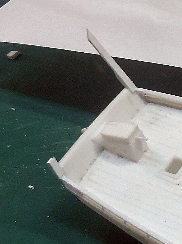
The photo also shows I still have a bit of sanding to do on the sides of the crank case.
I then cut the cylinder head away from its’ handle. Then the engine block from its’ handle.
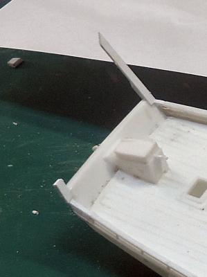
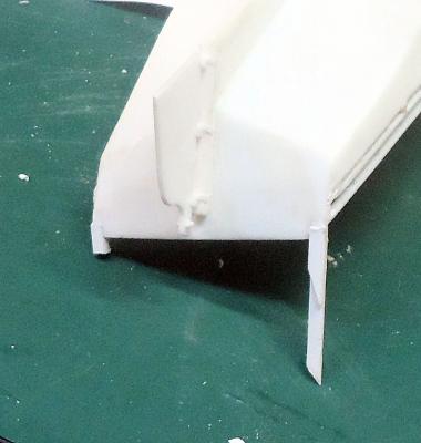
If you look close you can see that I cut the crankcase just below the crank shaft hole. The top of the engine from the mounting flange up is what protrudes above the hull’s cast in flooring. I also sanded the bottom of the engine block so that it leans toward the back of the boat. The engine was cut just below the crank shaft hole, leaving the hole in the engine block.
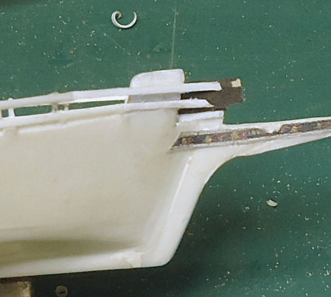
Here the engine block is set in the boat, to see how it looked. I had not yet sanded the angle in the base.
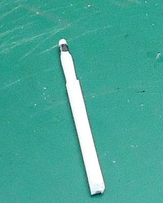
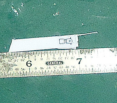
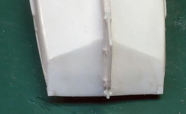
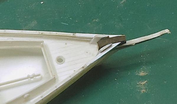
For the transmission, I found a half round sprue the right diameter. The bottom of this part would have mostly been cut off anyway, and I did not have any round pieces even close.
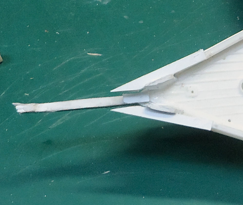
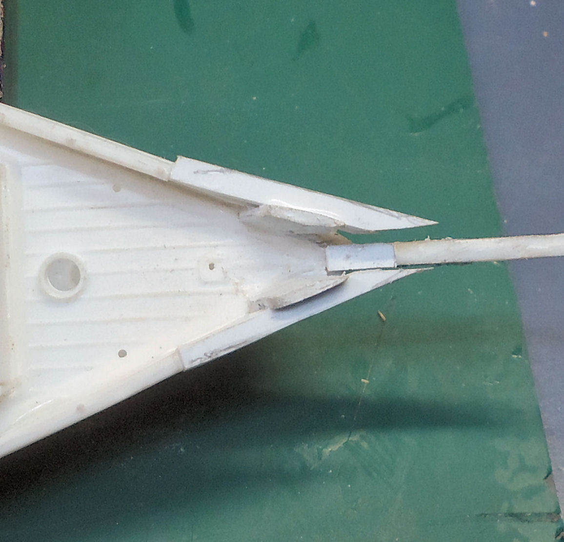
I glued the engine and transmission to a piece of .010” plastic sheet. This serves three purposes. The bottom of the engine that I did not model, was the section directly below the engine mounts, so the .010” will be cut to model these flanges. The transmission contact area to the engine is almost nonexistent, the sheet will serve to tie them together. I will leave a piece of the sheet projecting forward, temporarily. This will contact the back of the flywheel, and serve to mark where I should cut it. When I’ve cut the flywheel I’ll remove this section.
The black mark at the rear of the transmission is permanent marker, used to mark the top of the ½ round sprue. This helped when I was attaching it. With this small a part telling the round side from the flat with just my fingers was hard. I held it in place while gluing with the tip of a modeling knife. The sprue was a little warped, so I glued it in sections from one end to the other. I used thin liquid cement applied with a micro brush.
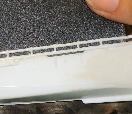
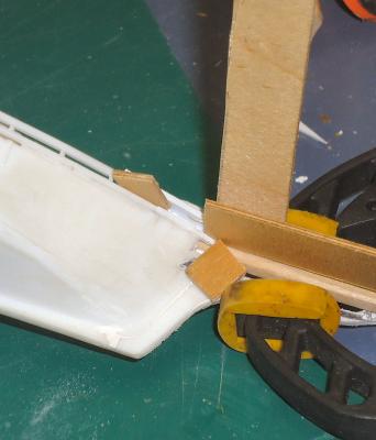
When the glue had dried, I cut the engine off the rest of the sheet. I used a piece of 1/32nd plywood as a spacer when cutting the engine mount tabs.
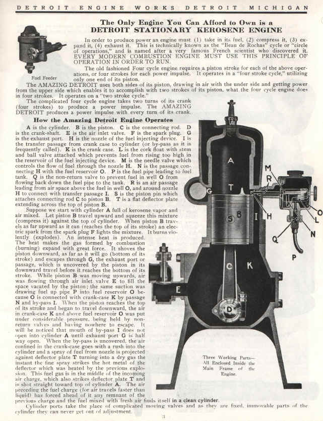
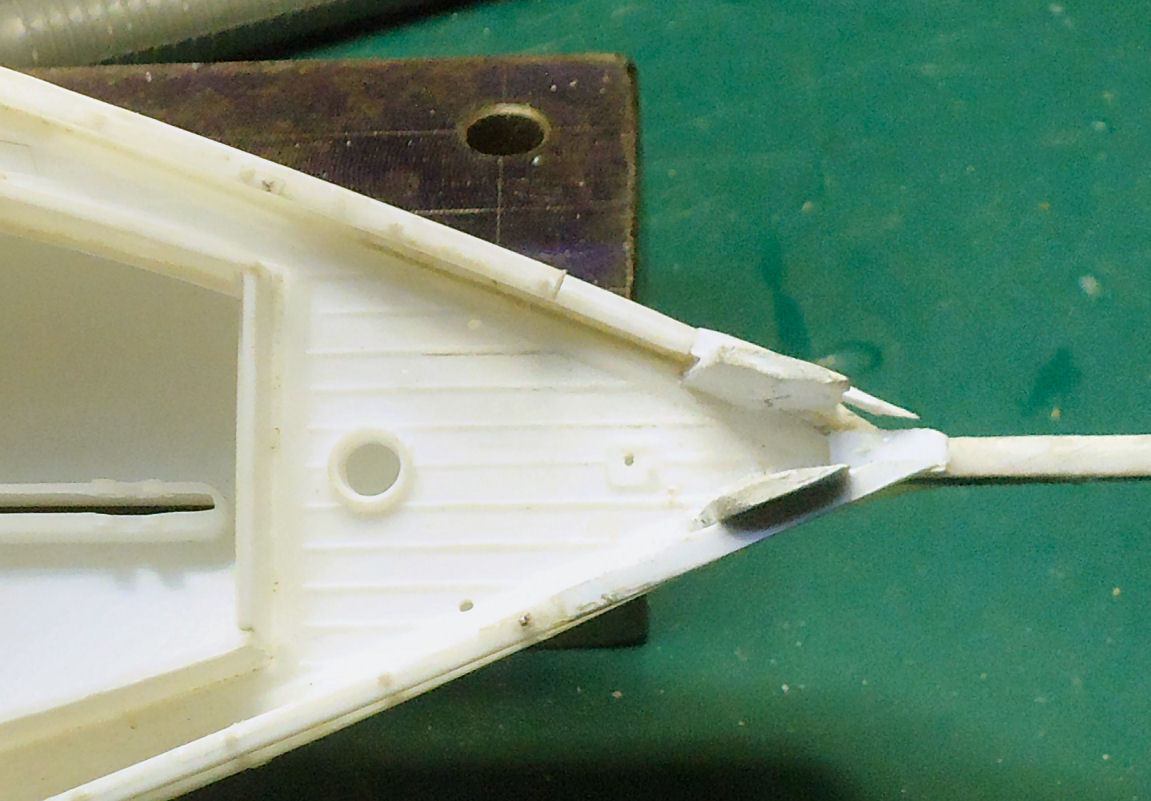
It used the engine to make a cardstock template for chiseling the hole in the push boat floor. I allowed what looked like a reasonable space for a scale hand and arm the reach into the hole and work on the engine.
I cleaned up the inside of the coaming, removing the last remnants of the seats, and smoothing the inside surface.
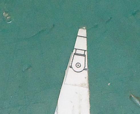
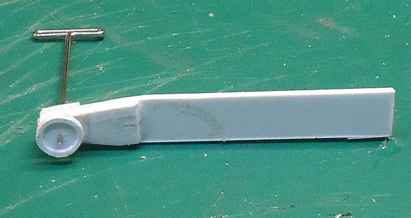
The tiller and rudder are molded in the neutral, straight ahead, position. This is a standard modeling setup. There is a problem with this on this model. If you look closely, the hole for one of the lift blocks, is in the center of the tiller.
I’m going to model the push boat with the tiller lashed to one side. I choose that the tiller would be lashed to the base of the aft lift block, on side toward the skipjack.
I removed the tiller from the casting, with a knife, file, and sand paper.
Then I angled the rudder to match.
Now what does the rudder have to do with the building of the engine, you ask. Nothing just felt like fixing this now. J
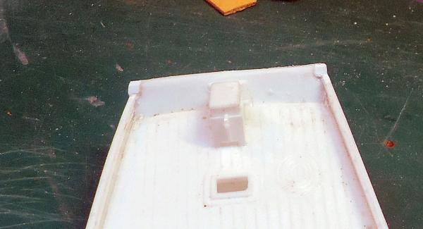
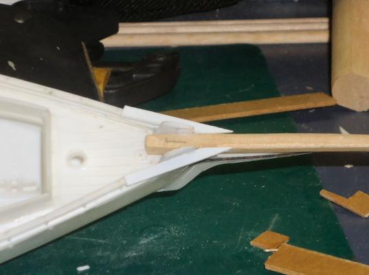
On the floor of the boat I darkened the center slat with a pencil, so that I could more easily place the pattern, I also marked where the front of the engine block would be. Then I glued in the pattern.
You can see the marked center slat behind the pattern. Once again I attached it with white glue, so I can remove any leftover glue, easily.
Originally I planned for the flywheel to be 4 scale inches from the engine block, and put something between them to represent a pump. When I trial fit the flywheel, this area was hidden by the flywheel. I decided to move the flywheel in to 2”, and forget the pump. The pattern was cut to include this change.
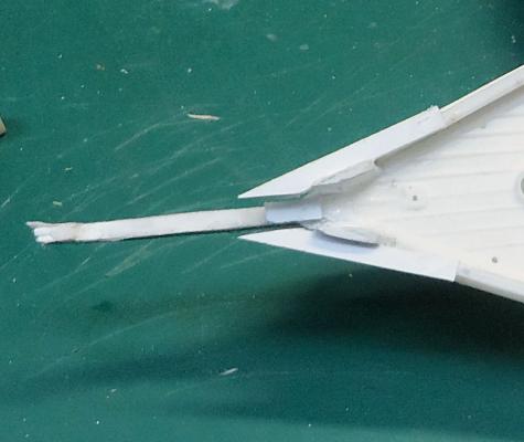
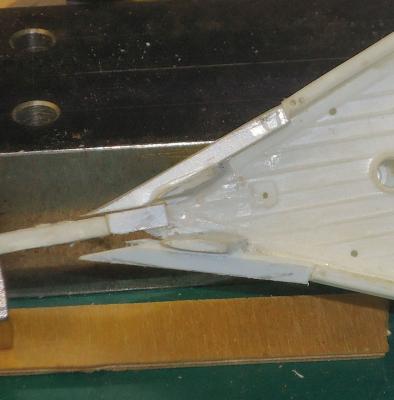
The cutout for the tail of the transmission will not extend back as far as the pattern, I needed a handle while installing it. I will cut the slot for the flywheel a little wider than the pattern, but I’ll do that during final fitting of the engine. I’m going to try to cut the flywheel slot a little deeper, to keep more of it, on the model.
I decided that the engine cutout for the block would end at the middle support, and that the transmission/prop shaft would end at the right hand one, and that all the cutouts would stop on the inside edge of a slat.