Mark P
-
Posts
1,774 -
Joined
-
Last visited
Content Type
Profiles
Forums
Gallery
Events
Everything posted by Mark P
-
 Good Evening Gary; She's coming on very well. Concerning the bolsters overhanging the cheeks, I have also seen the same instruction in several contracts. From what I remember, they always said 3/4 ", never 1 3/4" But you and the others who mentioned this are right, I would say: it does look better set back slightly, and that is the most likely reason for it being that way on models. All the best to you, Mark P
 -
Good Evening Vladimir; You are still making good progress, and your doubled-up deadeyes do seem to look the same proportion on their thickness as the ones in Rob's post showing the originals. Well done, very glad to see how quickly you are getting on. All the best, Mark P
-
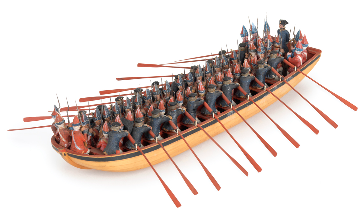
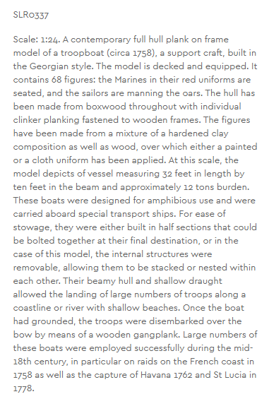
See below a picture of a model from the NMM of a troop landing craft, approx mid 18th century. Length is 32 ft, width 10 ft. Total number on board 68 men.
-
Thanks Allan for keeping these coming. Fascinating stuff! Re the purchasing power of a £500 reward for turning in the murderers of the Revenue cutter crewmen, it is a fairer comparison to say that an ordinary seaman around this time was paid £11 6s per year, less than £1 per month. This means that £500 would be the equivalent of more than 40 year's pay! Now that would certainly be a major inducement! This had been the same since the reign of Charles II. I am not sure what happened to pay after the mutinies in 1797, maybe it was increased then. Imagine the rate of pay not increasing for over a hundred years; different times indeed, with presumably much lower inflation. Prices did increase dramatically during the Napoleonic Wars, though. Did you see anything to say what happened in the smugglers' case. Was the reward claimed. All the best, Mark
-
Holes in Stem Post
Mark P replied to acaron41120's topic in Building, Framing, Planking and plating a ships hull and deck
Good Afternoon Allan; I would have agreed with Henry's post above, if you had not posted the picture. Certainly neither bumkins nor bobstays would be used for the Mayflower, as both came into use later. Your idea of staple holes is probably correct. It could be that several pieces of ply are fastened together temporarily to ensure that they all are worked to the same profile. The only other possible use I can think of is as holes to fasten filler blocks to receive the ends of the planks. But there is normally no need to fasten these through the stem. I do not think that these serve any construction related purpose. All the best, Mark P -
Good Afternoon Vladimir; She is coming along rapidly. You are a fast worker. Well done on deciding to rebuild the stern rail. If it does not look right, change it while you can, or regret ever afterwards that you did not. Keep up the good work! All the best, Mark P
- 200 replies
-
- 1
-

-
- cutty sark
- clipper
- (and 1 more)
-
FREE JOURNAL OFFER - COVID 19 COPING
Mark P replied to kurtvd19's topic in NAUTICAL RESEARCH GUILD - News & Information
Thank you and the other Committee members for the thought Kurt. Over here in England all the archives are shut for the duration. On the plus side, as you say, I can get on with the drawing side of my project, having more time than ever. All the best, Mark -
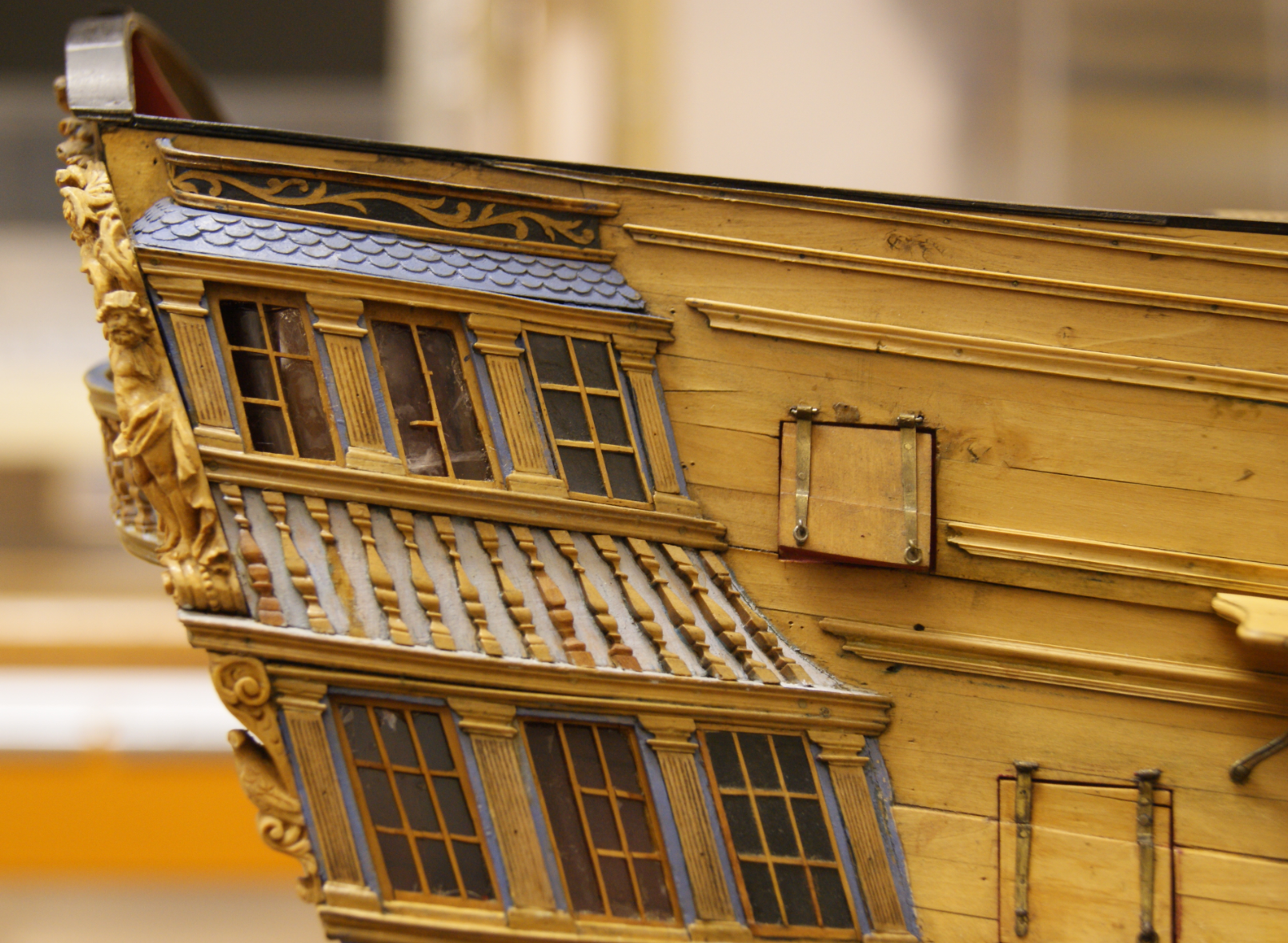
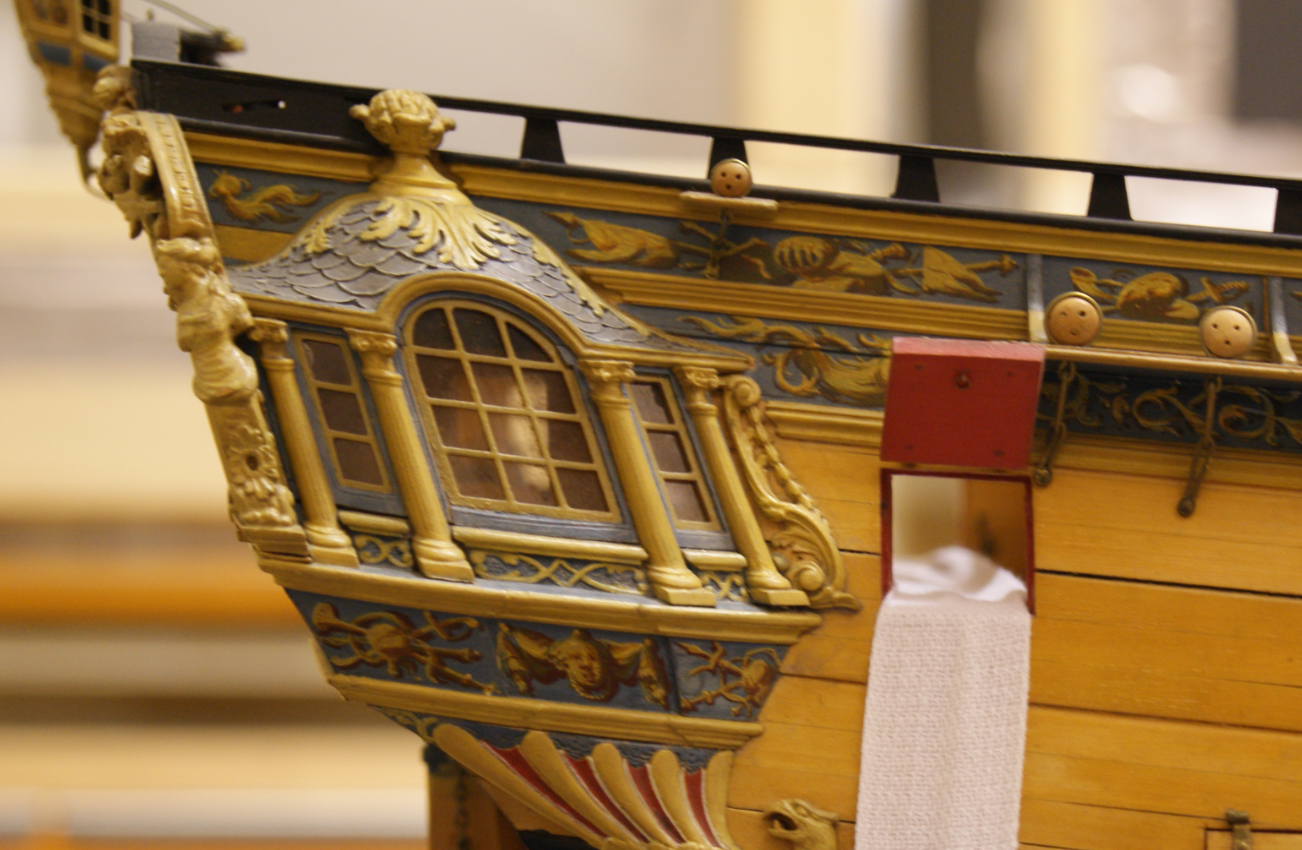
Good Evening Mark; I have seen references before to the fact that the deck in the quarter galleries did not follow the deck in the main cabin. I have also looked through my pictures of models, and although I don't have many looking at the quarter galleries square on, the one below is from Egmont, in the Science Museum. It is clear that the upper gallery windows follow the sheer of the ships mouldings etc. The bottom windows are slightly distorted due to their being below the centre of the camera lens (the model seems to have had a bit of a hard life, but the run of the windows is not affected by this) The shot below, of Endymion, shows the same thing. Regarding the curvature of the line of window cills and heads on the stern, the amount of curvature would increase with each successive level. This is one of the fundamental principles of elegant design. None of the curves on the stern are parallel to each other, although the difference is slight. The window cills will not be parallel with the deck, for example, but somewhat higher in the centre than at the sides. The picture of Victory actually illustrates this. The height of the moulded panel below the window can be compared to the height between the glazing bars. In the centre window the panel and the pane of glass are not greatly different in height. However, on the window closest to the side, the panel mould below is noticeably less in height than the pane of glass is. This can be confirmed by measurement of the photo. Keep up the good work! All the best, Mark P

-
Good Evening Vladimir; I will certainly take some for you next time I am at Greenwich. Unfortunately I am not sure when this might be. At the moment the Maritime Museum is shut, which is my reason for going to Greenwich. Until the government here relax the travel restrictions and things are more normal, I shall not be going past the ship. Very nice work on the bulwark stanchions. Keep it up! All the best, Mark P
- 200 replies
-
- 1
-
-
- cutty sark
- clipper
- (and 1 more)
-
Good Afternoon Keith; One possibility is that the two carrick bitts, one at each end of the windlass, had a pin rail between them, which could have curved round over the two bitts which hold the pawls of the windlass. I know that I have seen this on other draughts or models, although I cannot mention a specific example. That all depends upon how high the top of the carrick bitts etc was above the barrel of the windlass, as the coils of rope hanging from the pins would need to be clear of the cables. All the best, Mark P
- 1 reply
-
- 3
-
-
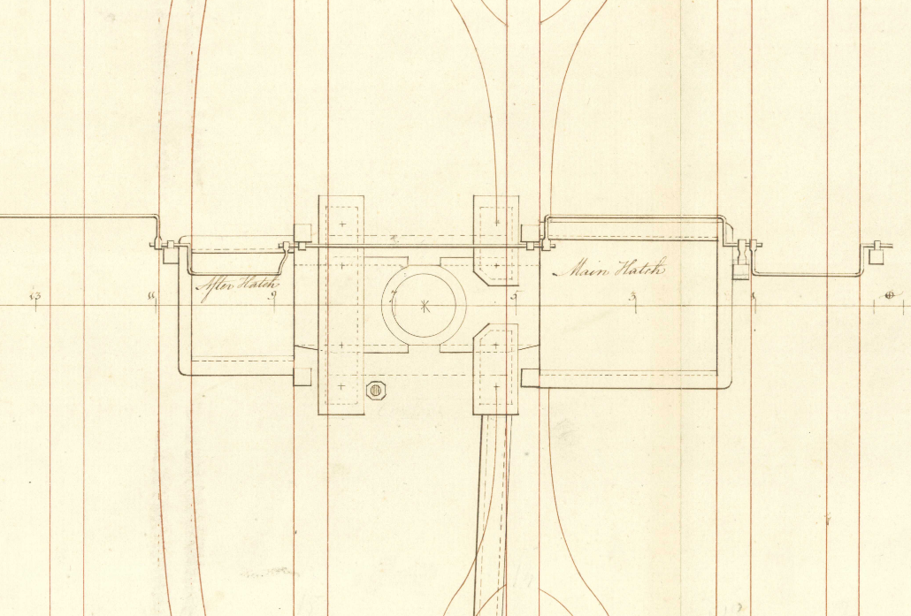
Good Evening Bluto; Regarding the chain pumps, you are quite correct. Two pump cisterns should equal four tubes, as each pump has a lift and return tube. Concerning the location of the elm tree pumps, I have looked through many deck plans, and they all seem to show only the chain pumps, either two or four cisterns, depending upon size. The extract below is from the deck plan for 'Ardent', a 64 gun ship of 1782. The small octagon adjacent to one of the chain pumps indicates an elm tree pump. All the best, Mark P
-
What is a jewel iron and what does it look like?
Mark P replied to Roger Fyre's topic in Masting, rigging and sails
Good Evening Roger; Whilst I agree with WE's comment above, I also seem to recall that a rigging block fixed to the end of a yard was called a jewel block. Your diagram might mean this. Can you post a picture, which would probably settle it. All the best, Mark P -
The Master Shipwright’s Secrets, by Richard Endsor. This new book from well-respected author Richard Endsor sets out the latest fruition of his ever-deeper researches into Restoration era warships. The book is large format, approx 260 x 310mm, and has 304 pages. It is lavishly illustrated throughout: there are many colour depictions of a variety of vessels and scenes from the author’s own hand, as well as a plentiful quantity of folding plates of plans and draughts, at a scale of 1:72 The great majority of these are in colour also, and are again by the author. In addition to these there are a variety of prints by the elder Van de Velde, again in colour; good colour illustrations from other sources; and a decent quantity black and white line line drawings where necessary to explain points discussed in the text. The folding plates and accompanying draughts are all based on the author’s reconstructions, using contemporary sources, of several vessels built during the closing years of the Charles II’s reign. These are as follows: 1: The Mordaunt, a 40 gun fourth rate, of which there is a detailed contemporary model in the NMM, a survey of which forms the basis of the reconstruction, along with a contemporary survey of her made at the time of her purchase from Lord Mordaunt, who had had her built as a privateer. 2: The St Albans, a 50 gun fourth rate, of which there is a contemporary model in Trinity House, which was carefully surveyed in the early 20th century. The resultant drawings and the model are used as the basis for the reconstruction given here. 3: The Tyger, a 46 gun fourth rate. The reconstruction here is based on those of the other vessels, and a variety of contemporary documents. The most important of these is a carefully calculated series of mathematically derived offsets, written down by Jonas Shish, the Master Shipwright at Deptford Yard, who designed and oversaw the building of this ship. Although the offsets do not quite match the overall dimensions of the Tyger, and were compiled a couple of years before she was built, they are for a very similar vessel. This list of offsets and associated dimensions is the ‘Secret’ of the title, and appears to be a unique survival from the period (no other such list is known anywhere) Any of the reconstructions of the various ships listed above have sufficient information to enable a reliable model to be built. As mentioned in a post I made a short while back, the importance of the table of offsets as a factor in ship design is a major discovery. It proves that the design of ships at this period was based on sound mathematical principles, some of which are complex and not easy to grasp. The book sets out in a clear fashion the basic lines which determine a ship's design, and the variety of methods used to draw these. There are four in total: the rising line of the centres of floor sweeps; the narrowing line of the centres of floor sweeps; the rising line of the centres of breadth sweeps; and the narrowing line of the centres of breadth sweeps. By combining these four curves with the station lines, the centres from which all the main curves of the body plan are struck can be located in three dimensions. None of the methods of drawing these four curves is simple, all needing some considerable skill to master; one relies on the use of factors, which is something beyond the understanding of many people. Nor are the curves necessarily of a constant radius, as this can be varied as they progress along the hull. I believe it is safe to say that the chapter dealing with these offsets, and the techniques for drawing the four basic lines, will bring a welcome addition to the knowledge of every reader. The book opens with chapters describing the typical features of the ships of the time, and has comprehensive coverage of what would be found on board, as well as a well-informed narrative of the environment in which they had to operate, and the factors which influenced their design and building. The Tyger is the main subject of the book, which was built for service in the Mediterranean, in response to the threat from Barbary Pirates there. Their depredations amongst merchant shipping and the fate of the crews as slaves or prisoners was a constant concern in the 17th century. They also made raids on England’s South coast. The frequent lack of winds in the Mediterranean meant that ships with the ability to row were needed. Earlier efforts by Charles' Naval administration had built vessels with many oars, but not heavily-armed. This had been shown to be a weakness, and the new design of the Tyger was for a ship which could be easily rowed, but which also carried a decent broadside armament. The old Tyger, a ship built in the Commonwealth era, was taken apart for repair in the 1670s, at Deptford Dockyard, and became no more than a few timbers stacked in a corner. However, she was maintained as an active vessel on the Navy list, so that a number of wounded seamen could receive salaries as her standing warrant officers. This was one of the King's ways of supporting deserving men who were no longer able to be active sailors. Charles II’s part in the design of his ships is made clear, and it was extensive. He was a very knowledgeable king, who loved ships and the sea, and understood a great deal about their design. He devoted large amounts of his time to the creation of the Navy, and would discuss aspects of design and seamanship with many people, including those from ordinary walks of life. He was also a faithful patron of Jonas Shish, and stood by him when any problems with Shish’s superiors needed to be settled. Well aware of the need to build a ship to deal with the corsairs, but short of funds, and knowing that Parliament would not easily vote for further money for another new ship, Charles hit on the idea that the Tyger, although not really existing in any physical form, could be ‘repaired’ using funds from the existing repair budget. Working closely with Jonas Shish, a new ship was designed and put into construction at Deptford. One consequence of the secretive building was that the resulting vessel’s considerably larger size was not drawn to the attention of the Navy Board until after they had allocated to her a set of guns based on the old vessel’s size. The remainder of the book contains a thorough description of the new Tyger, and shows much detail of her internal fittings and machinery. A detailed, colour set of rigging plans, sail plans, and mast and yard dimensions is also given. The belaying points are not given, but as there is no contemporary source for this, this is understandable, and such information can be gleaned from modern works and contemporary models if needed. Her armament is discussed in considerable length, and again is well-illustrated in colour. Gun carriage reconstructions are given, based on a surviving example on a tower at Windsor Castle, of all places; and a carriage recovered from the wreck of the London, which exploded and sank near Southend in 1665 (her wreck, a valuable source of artefacts and knowledge is being rapidly eroded and a campaign is under way to try and recover as much as possible, or even to raise the remains; see www.nauticalarchaeologysociety.org/Appeal/save-the-london ) Looked at from any point of view, this book is a deeply useful resource for modellers, historians and archaeologists alike. The many reconstructions offer a great depth of information, and the analysis of contemporary sources is thorough and well-explained. There are a number of 17th century ship-building contracts as an appendix, and a well-illustrated glossary. The book is priced at £65, and is published by Osprey books. It is available from all the usual sources. I highly recommend this as an addition to the library of any serious modeller. All the best, Mark P
-
Good Morning Siggi; Lovely work on the cannons. I congratulate you on your skills. Regarding the number of cannons on board, it is not always necessary to count the foremost port on the gun-deck. This was frequently what is known as a bridle port, and was used to help attach the cat-block to the anchor ring once the anchor had been raised to the water's surface by the capstan. No cannon was fitted if the port was intended for this kind of use. As you point out above, the manger is in the way of the cannon's recoil. In these circumstances, it would seem safe to assume the port is a bridle port, especially if it is smaller than the other ports. All the best, Mark P
-
Good Morning Vladimir; She's coming on fast. Well done for altering the bow, it looks much better. The stern looks good also. All the best, Mark P
- 200 replies
-
- 2
-
-
- cutty sark
- clipper
- (and 1 more)
-
Good Morning Popeye; Thank you for the clear explanation. That makes perfect sense of it all, and fills in the gaps in what I knew. Now if you can fill all the rest of the gaps which still remain..... It also means that the illustration in Lees' book, showing the driver as an alternative to the mizen sail (p 112) with no obvious reason why it should be replaced (the area of the sail is almost identical) is incorrect. The driver actually worked with the mizen, to extend its area, as your post makes clear. All the best, Mark P
-
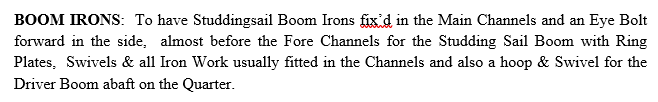
Good Evening Bob; Thank you for your thoughts and the video. I can see that you know a great deal about sailing square-riggers. However, you seem to have slightly missed my point regarding the driver/spanker. I do not know how old these terms are, but the first use of them of which I am aware occurs towards the end of the 18th century, and is to name the sail fixed to the mizen mast of a three masted ship, and is unconnected, at that time, with the later development of merchant ships with more than three masts. My query was in relation to the development of that particular sail, not the mast. It is necessary to remember that the original question in this post concerns the Leopard, a Royal Navy ship launched in 1790. Navy ships were never fitted with mizen studding sails, so there is nothing to be gained from trying to make this item relate to a mizen studding sail boom. The quote from the contract for Fortitude is quite specific, in that it talks about the 'driver boom', and this can only be in relation to the sail, attached to the mizen mast, the existence of which is an acknowledged fact and is the subject of many paragraphs in books on the rigging of Navy (and other) vessels. It is possible that the name of this sail later became used for an additional mast with a driver sail attached, on merchant ships, but that is beyond the scope of the original query in this topic. Regarding whether or not it would be possible to rig and re-rig a rather small sail when going about, it is not a valid comparison to describe what was done in later days of merchant sail, with relatively small crews whose size was dictated by the needs of profit generation. The Navy ships of the 18th century had crews in the multiple hundreds, and would have had no problem with finding sufficient men to perform such a manouevre. In the days of the lateen mizen, going about involved passing the fore end of the mizen yard, which protruded many feet in front of the mizen mast, to the rear of the mizen mast and then re-positioning it on the other side of the mast. This must have been a lot of work, and would have required large numbers of men, and yet it was a matter of routine. What I was wondering about in my afterthought post was whether or not the original driver sail started as a studding sail type cloth rigged to the head of the gaff, and with its foot attached to a boom fastened in the quarter. This would seem to be a reasonable hypothesis, as a short-term stage in the development process from loose footed mizen sail to a driver sail with a full-length swinging boom on the mizen mast. Any further thoughts on this, in regard to Naval vessels, would be welcome. Added a little later as a further afterthought: it would also seem a reasonable hypothesis that the driver boom referred to above is actually used in conjunction with the loose footed mizen sail, and was used to extend the aft-most corner of the sail outboard of the stern, thereby providing a means to increase the sail area. This could then easily have led, in a relatively short period, to the introduction of the driver boom, with which are all more familiar, which extended from the mizen mast, and performed the same function. All the best, Mark P
-
Thanks Allan; It's amazing where a quest to ensure that the model you build is as accurate a depiction as possible will take you! I now get as much fulfilment from digging through archives as I expect to get from my next model; the draught for which is well under way. All the best, Mark P PS: see back to my previous post for a new thought.
-
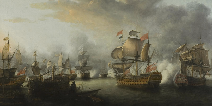
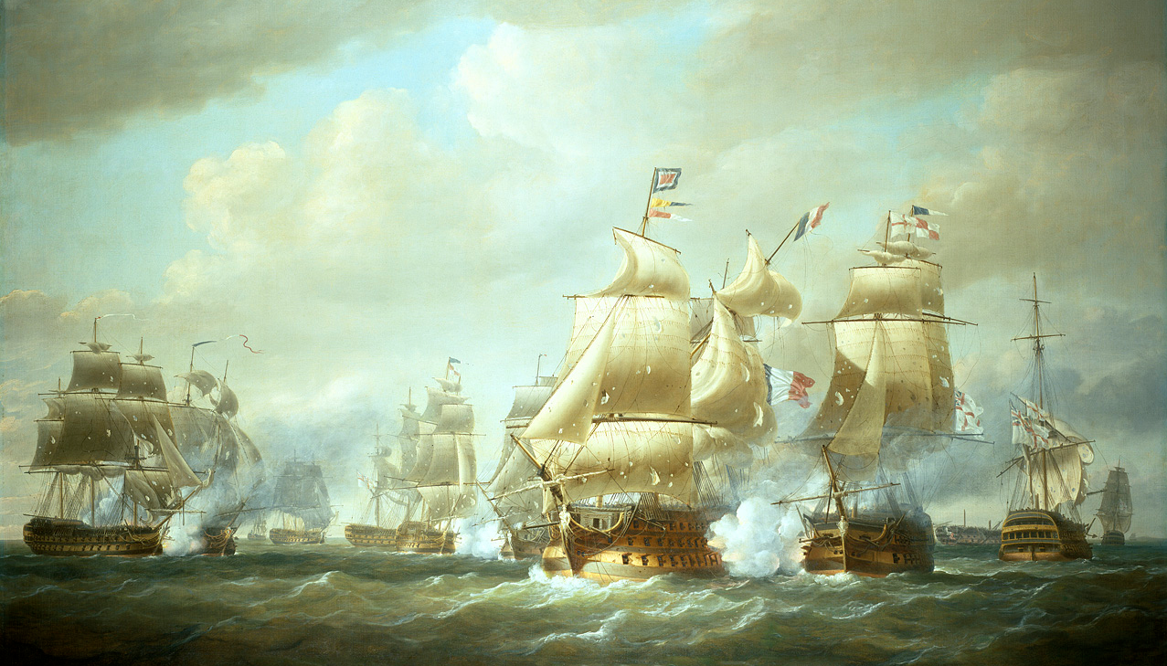
Good Morning Everyone; An important point to keep in mind here is that the fore and aft rigged sail on the mizen mast evolved considerably over the years. In the 17th century, all ships of any size had a lateen yard, with a triangular sail. This had no boom at its foot. This mizen sail then became shortened, so that although the yard remained at the same length, the sail ended at the mast, becoming four-sided, with the luff laced to the mast or perhaps hoops on it. This sail was still called the mizen sail, and was loose-footed, with its free corner controlled by the sheets. This sail did not extend aft of the taff-rail, and, in common with its predecessor, did not interfere with the ensign staff at the stern when going about. Numerous paintings from this period show the ensign flying from the ensign staff at the stern while the ship is under sail. Models from this period show that the ensign staff was indeed hinged at its base, normally by inserting the foot into a pivoting block, and retained in the upright position by a metal clasp on the taff-rail. The boom at the foot of the sail was only introduced in the last two decades of the 18th century. There may have been a transition phase, during which ships for a while did indeed lower and raise the ensign staff, since it was already fitted in a manner to allow this to be done. Doubtless the realisation that this was not really practical set in quickly, and the custom of flying the ensign at the gaff peak when under sail became customary. Below is a painting of the Battle of the Saints, 1782, by Nicholas Pocock. All ships have ensigns flying from the staff, and loose-footed mizen sails. Below is a painting of Duckworth's action of San Domingo, by the same artist, but dated 1806. All ships have the ensigns at the gaff peak, and on several of them driver booms can be seen at the stern. None has an ensign staff rigged. James Lees, in his book on rigging, gives the date of the introduction of the driver boom as 1793. However, the contract for Fortitude, a 74 gun ship, signed in 1778, specifies a driver boom crutch on the quarter. This was presumably to rest the boom in when not under way, as was certainly done later, to take the strain off the rigging. It would be interesting to know what length the boom was when first introduced. Did it extend beyond the taff-rail or not. I am not sure when the driver became the spanker, or what the exact difference between them was (my main period of interest stops at around 1790) but both needed a boom at the foot. All the best, Mark P Added an hour later as an afterthought, on further consideration: Is it possible that the driver, when first introduced, was actually rigged in a manner similar to a studding sail, with a boom on each quarter, and the head fixed to a short yard hoisted up to the gaff. This sail being un-rigged before tacking, then re-set on the opposite side afterwards. The ironwork on the quarter, referred to above, actually seems to describe such an item. However, I have no idea if drivers were ever rigged in this manner. Lees depicts a driver with a short yard, hoisted to the gaff, but in conjunction with a full-length boom pivoting on the mizen mast.
-
Good Morning Vladimir; You are making good progress. She is certainly a big model! Nice work with all the bits of machinery on deck. all the best, Mark
- 200 replies
-
- 2
-
-
- cutty sark
- clipper
- (and 1 more)
-
Congratulations Vladimir on all your work. She looks impressive. Are you going to fit masts and rigging? Keep up the good work. I shall follow this with interest. I visit the Maritime Museum at Greenwich as often as I can (I use the archive there) and when I get off the Underground I walk past the Cutty Sark. If you would like some pictures let me know. Not sure when I will be going again though, with all this virus trouble at the moment. All the best, Mark P
- 200 replies
-
- 1
-
-
- cutty sark
- clipper
- (and 1 more)
-
Two train tackles is definitely wrong. The trucks are all the same size also, which I would be very dubious about. Also, when a gun is run out for firing, the train tackle would not be attached. The solid bed of the carriage is quite right, though. The barrel should be lower in the carriage also. It appears to be sitting much too high. The top of the trunnion was located at the horizontal centre line of the barrel. A minor point is that the gun, if fired, would recoil over the rope of the gun-tackle, which, if it was trying to run through the blocks at that moment, would snap the rope like a thread. Tackle falls were laid clear of the recoil path. I would also check on whether or not double blocks would be in both ends of the gun tackle. It may well be a single and a double. All the best, Mark P
-
Good Evening Everyone; Thank you all for your helpful suggestions. Wayne, thank you for the offer. if I ever do manage to locate a copy, I will let you know. I found the Anderson article previously. Chuck, I have already contacted Kurt, and he was unable to find out anything about it. Certainly there are no copies lying around at HQ, more's the pity! Dave, I do have a copy of Marquardt's book, and the appendix is very useful. But from what I have read, the remainder of the book would be full of information also. Thank you for the thought, though. All the best, Mark
-
In 1711 John Davis, who had been boatswain on various ships for the last 30 years, published a book called 'The Seaman's Speculum, or Compleat Schoolmaster'. This has extensive rigging tables, and much other useful information. Unfortunately it now seems that no original copy exists, as none of the major repositories hold a copy. The only seeming survival is a volume which existed in 1945, and had been acquired by the library of the US Navy Department. Not sure if this copy still exists, and if anyone here has contacts with the library, would they please ask about it. The Smithsonian has a photocopy, but as it is a photocopy they do not supply copies of it. However, in 1985 the NRG published a limited edition reprint of 200 copies. If anyone here has a copy of this reprint, and would be willing to either sell it or send me a copy (I will ask the NRG for permission for this if required) I would be very grateful. All the best, and hope to hear from someone soon! Mark P
-
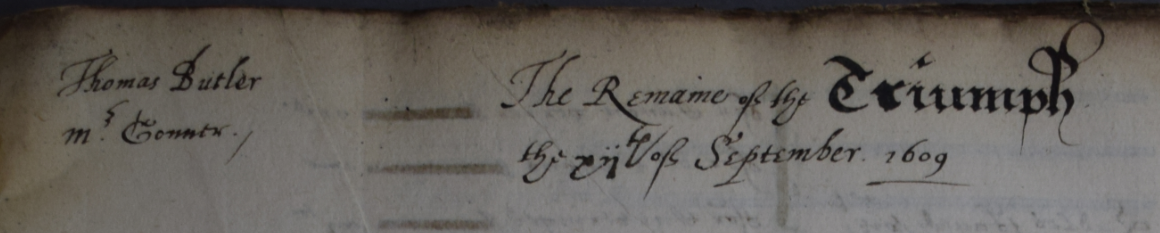
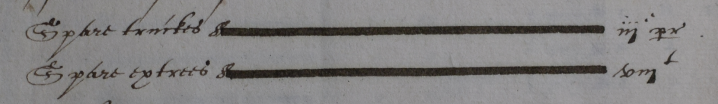
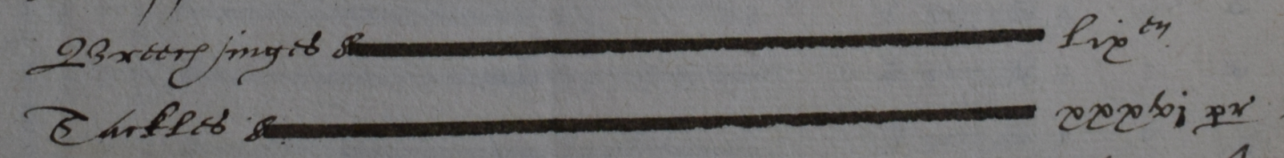
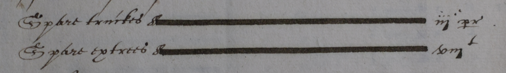
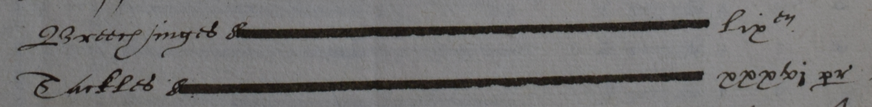
Good Evening Everyone; Further to the query above about the use of tackles, see below excerpts I have just taken from a list of gunner's stores which were remaining in the Triumph when surveyed at the end of a voyage. This is dated 1609, and quite clearly lists both breechings and tackles. Unfortunately it does not give lengths, but I will look further, and see what I can find for other dates. The first one is just giving the date (12th September) and vessel: The second one gives spare truckes iii pr (3 pairs) And spare extrees (axletrees) viii (8 I am not sure what the 't' means; it might just be part of the spoken sound 'eight') And the last one gives Breechinges lix (59) (not sure what the 'e' something means) And Tackles xxxvi pr (36 pairs) Her total armament in this survey is given as: 4 cannon perriers; 3 demi-cannon; 19 culverins; 16 demi-culverins; 13 sakers; 4 fowlers; and 8 chambers for them (not sure which guns the chambers were for) This information is from a record in the National Archives at Kew. All the best, Mark