HOLIDAY DONATION DRIVE - SUPPORT MSW - DO YOUR PART TO KEEP THIS GREAT FORUM GOING! (Only 13 donations so far - C'mon guys!)
×


Mark P
-
Posts
1,770 -
Joined
-
Last visited
Content Type
Profiles
Forums
Gallery
Events
Everything posted by Mark P
-
 Good Evening Mark; Maybe you could taper the discharge chutes slightly, which would help. Only a couple of inches or so. All the best, Mark P
 -
Good Evening Kurtis; The cheeks are a lot better now, certainly. The overall impression is much improved. Still let down by the stern and the wale. Look at Malachy's and see if you can work out the difference. If you can improve the stern, you will have a passable impression of a ship, which, if it is all you are wishing to achieve, is a good first step on the long road to self-improvement. If you are seriously going to involve yourself in this, I recommend that you keep a copy of this drawing safe, and look at it in 10 years; and 20 years; and 30 years. You will think: 'OMG! Did I really do that?!!' All the best, Mark P
-
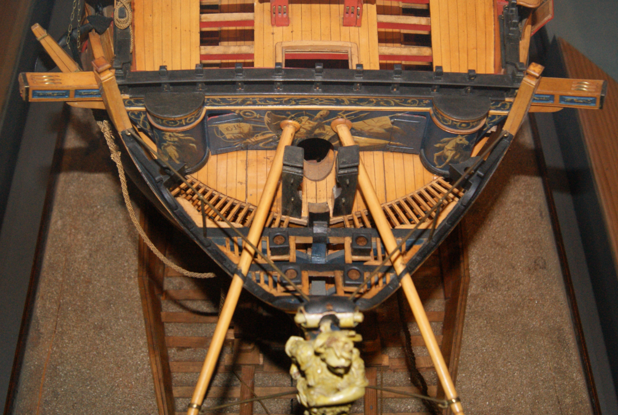
Good Evening Mark; See photo below from a different perspective. It does look as though the foremost discharge chute (by the way, good pun Druxey!!) is set so that the lower rail is protruding somewhat across the exit, but only a couple of inches at most. Also, the cuts in the head timbers for the rails look much smaller than those on your section, which would weaken them quite a bit, I suspect. All the best, Mark P
-
Good Evening Mark; Look again at the second photo in my post, looking up from below. the inner face of the discharge chute is resting on the top of the lower rail, but the chute is not at all obstructed by the rail. Something must be still a bit amiss. Both seats of ease sit on the headrails, but without obstructing the holes. Certainly, the rails will get some splash, and the bosun's pet whipping boy probably got the happy job of swabbing it clean in harbour. All the best, Mark P
-
Good Afternoon Druxey; Thank you for pointing this out, but I checked this first, and the Wikimedia Commons licensing statement says that no permission is required for use for any purpose, as this image has been in the public domain. Although the original text of the title of the drawing could be considered copyright. All the best, Mark
-
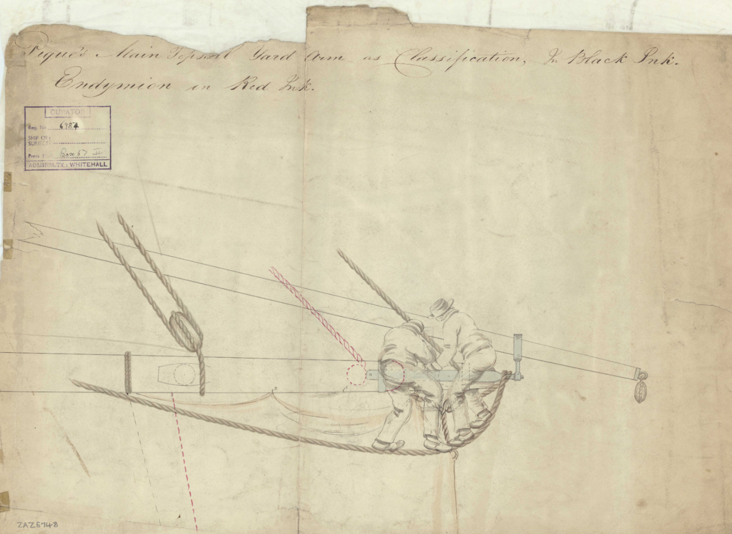
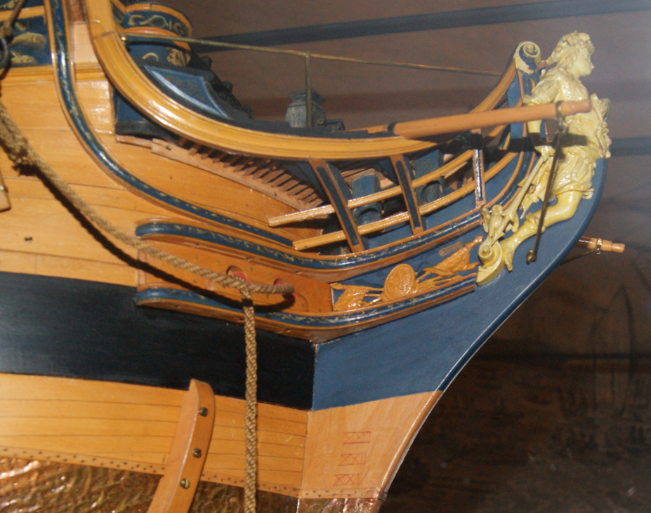
Hello Everyone; Just came across this interesting little illustration whilst searching through a bunch of draughts downloaded from Wikimedia Commons. This shows the main topsail yard-arm of Endymion, a 44-gun ship launched in 1797. This gives an idea of how big the yard-arm and studding sail boom irons actually were. all the best, Mark P
-
Good Evening Reg; I've just looked at the back of my volume IV, and Druxey is right. The rigging plans etc are indeed there. I had forgotten about them. One thing to keep in mind though: whilst the Swan volume IV is a very helpful and wonderful guide to the rigging of the period, it is all dimensioned for a 14-16 gun sloop. Winchelsea is a frigate with 32 guns, so her rigging will be on a different scale. Nonetheless, the book is an invaluable aid if you want to learn about rigging. All the best, Mark
-
Good Evening; I agree with Jaager, even if it is not seasoned it still sounds too good to miss. All the best, Mark P
-
Good Evening Reg; If you are referring to the fourth volume in the 'Swan' series of practicums, I have this, and I can highly recommend it to you. It is very well illustrated and explains everything in great detail. However, there is also a supplemental, smaller volume which was issued later, which gives further details of some areas of the rigging, I believe. I don't have this, so I cannot comment on it. But I would advise you to purchase both volumes if you can, as I don't doubt that it is to the same high standard as all David Antscherl's books. I did not purchase the plans, only the framing templates, so I can't answer your other question about the masts. But there will be many other members here who can. All the best, Mark
-
Good Afternoon Mark; Here is another one, taken from directly abeam. All the best, Mark P
-
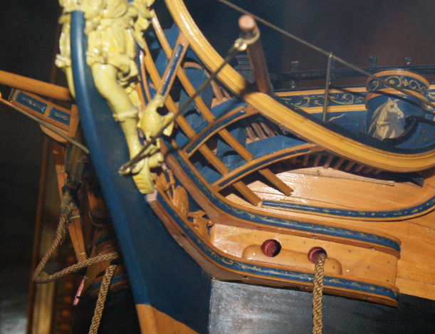
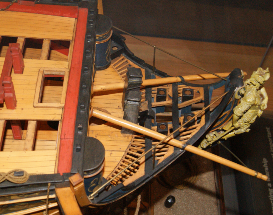
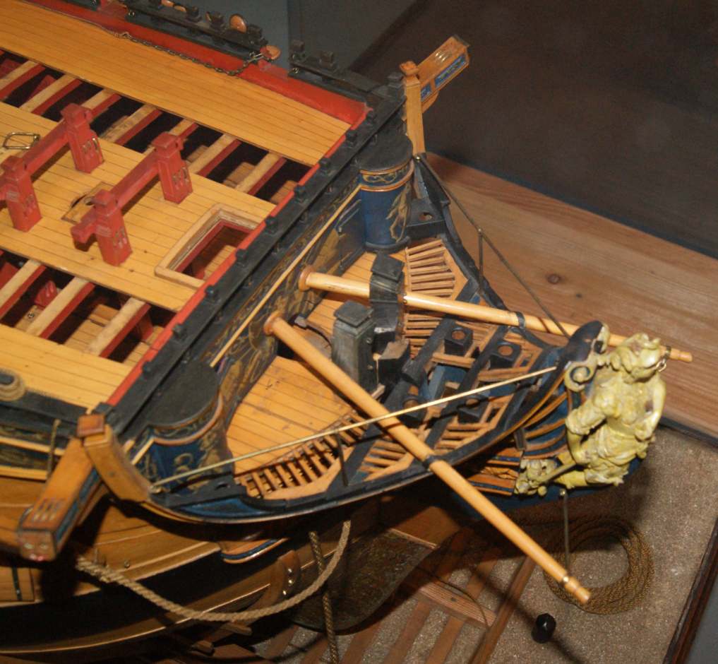
Good Afternoon Mark; See below a few photographs of the model, taken while she has been on display at the NMM. Unfortunately this meant that I was not able to photograph the port side or the stern. These will be invaluable in working out the location of the seats of ease, though, and much of the other detail. The discharge chutes seem to be sitting on the headrails, which presumably gave them the support they needed. The final photo is from 'Endymion', a 44 gun ship, but shows the location of the chute clearly. All the best, Mark P
-
Good Evening Papa_Raigin; Welcome to a very rewarding hobby! I know something of the Great Michael's history, and it appears that there is very little documentary evidence surviving about her, a fact which has been mentioned with regret by other researchers into the history of ship development. Her dimensions are given as 240 feet long, with an internal breadth of 35 feet plus, supposedly, 10 feet of timber each side, which would give a total breadth of 55 feet. Ten feet of timber each side sounds highly unlikely, and would dramatically increase her displacement. Unless Lindsay, the Scottish chronicler who gives these dimension, meant ten feet in total, five feet each side. However, even assuming the breadth was 45 feet gives a length to breadth ratio of approximately 1:5.5, which is extremely unlikely for a ship built in the early 1500s, when most carrack type ships had a length to breadth ratio of between 1:3 and 1:4 I mention this only to make you aware that if it is not possible to be certain even of her principal dimensions, then there is no real prospect of having much of an idea of anything about her. As she ended up in the French Navy, their records might hold something about her, but it will not be easy to search there for you. This means that you have a choice between making a model of her based on pretty much whatever you like, or you will, unfortunately, need to search for a different ship to model. No ship from this period is known very well, as the evidence is scant, and reconstructions all contain many assumptions. I wish you all the best with whatever ship you model. Mark P
-
Good Afternoon Paul; Yes, you will need a chamfer on the bottom edge of one strake, and the top edge of the corresponding strake. The amount of overlap stays constant, but the angle of the chamfer changes. It will be approximately vertical where it starts, and around 45 degrees by the time it reaches the stem/stern. The rabbet will be as you describe. All the best, Mark P
-
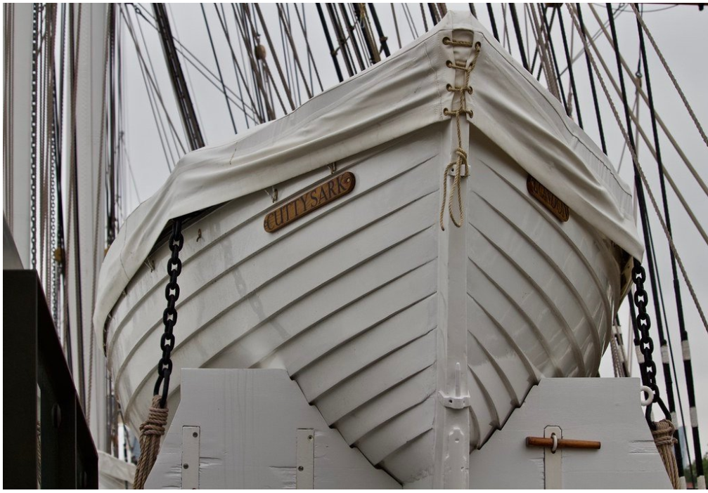
Good Morning Paul; There was a very clear photograph posted recently by Vladimir Wairoa in his build log for the Cutty Sark model he is building. This shows the run of the stern planking beautifully (this is the stern, note the rudder pintles, must be a whaler; although the bow would be identical in a transom-sterned boat) In conjunction with Jaager's post above, this should make things clear. As well as a rebate, the planks can have a chamfer between them, to a line drawn between the two internal angles. this is easier to construct on a model. All the best, Mark P
-
Good Evening Mark; It is possibly just a fancy terminal on the spear. some had a spike on the reverse end, so that when it was used in a defensive formation, the end of the spear could be fixed in the ground if desired. Note also the chicken/cockerel by her foot. Is this the same type of bird as in the model's figurehead. Does the chicken/cockerel have a significance for Bellona. The Romans used sacred chickens to provide omens as to whether or not to attack, guided by the way the chickens ate their grain. One famous general, waiting to launch an invasion from a fleet, threw the chickens overboard when they failed to eat in the desired manner, saying "If they will not eat, they will drink!" or something like that. Something slightly odd: we have many words meaning war, or warlike, all rooted in 'Bellum', latin for war. Bellona, belligerent, bellicose, ante-bellum, parabellum. Yet the Italian word 'bella' means beautiful. All the best, Mark
-
Good Morning Vladimir; You are still working hard I can see. The speed of progress is remarkable, and I agree with Alan above, your resourcefulness in using other objects as substitutes to obtain the desired look is ingenious. Keep up the good work. All the best, Mark P
- 200 replies
-
- 1
-

-
- cutty sark
- clipper
- (and 1 more)
-
Good Morning Mark; Some good advice: listen to your wife; especially when so many of the other forum members agree with her (not that the latter consideration should influence you as much as the first, of course!) All the best, Mark
-
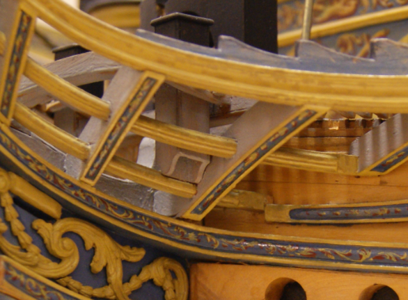
Good Evening Kurtis; I still advise you to devote some hours to study of models and pictures. The purpose of this is not to transcribe anything, but to compare the picture/model with what you have drawn, and look for differences. If something does not look the same, try to work out why. The 'Bellona' has an excellent series of photographs on the NMM collections website. Have you looked at these? Full colour, lots of different views, and a zoom function (although it never gets as big as would be really helpful) There is also at least one rigged model of a 74 shown. There is also a book by Brian Lavery, about the Bellona. You may already have this; if not, I would certainly recommend that you acquire a copy. This is one of the Conway Maritime Press 'Anatomy of the Ship' series, and is only available on the second-hand market, but many tidy copies exist. If you are not intending to create a fully-detailed likeness, then it is a matter of ensuring that the general impression does not look notably erroneous. To help you, I will list what I see as the most obvious areas for improvement. If you do not know the parts referred to in the following description, try an internet search using the word, which will assist you in learning their meaning. Most of them will get many hits, I am sure. I will not list any missing items, as I will assume that you have not yet got round to adding these. The quarter galleries I will likewise assume are still a long way from completion. To start at the stern: 1: The rudder should taper from top to bottom, and follows the taper of the sternpost. The top is approximately square. You have the top much too long in the fore and aft plane, and much too narrow in the thwartships plane. 2: The shape of the stern below the tuck is completely wrong. There should be a streamlined diminution so that the planking just forward of the sternpost is no wider than the sternpost. If the water cannot flow past the rudder in a smooth run, the rudder will have eddies on each side, and will not work well. The hull planking at the stern should also round upwards to meet the tuck, forming what is known as a 'round tuck', the technique used for almost all warship sterns at this period. 3: You show a sharply defined edge where the vertical plane of the side of the keel meets the hull planking. Whilst this is often correct in the midships area, and for some distance fore and aft, it did not happen at the stern, where the planking should fair smoothly into the keel. 4: You appear to have correctly picked up the main wale in the midships, but at the stern it should rise up much more, and meet the end of the tuck mould. 5: The line of the fife rail on the poop/roundhouse should continue in a smooth flowing curve all the way to the outer edges of the taffrail at the stern timbers/side counter timbers. 6: The run of the headrails is very wrong. They look like a fence, which they are not. The main rail should run up to meet the ends of the beakhead bulkhead, the middle rail terminates where it meets the bow planking, and the lower rail meets the bow planking in a manner similar to the middle rail, then sweeps aft and upwards to terminate in a supporting knee under the cat-head. 7: The cheeks are likewise very wrong, and should be much more 'L'-shaped in plan. The forward ends need to curve upwards following the forward edge of the knee of the head. 8: The knee of the head is much narrower thwartships at its foremost point than it is lower down, and near the top its foremost edge is noticeably rounded off. All the best, Mark P
-
Good Afternoon Kurtis; You obviously have a talent for computer modelling, and it is a shame to see it being rather misdirected. I would suggest that before you go any further you devote some hours to a search for pictures of 74 gun ships from the period you are aiming at. This is because there are a large number of unfortunate errors in your drawing. If this is just a drawing exercise for your own pleasure, or if you are intending it to be for gaming then this is not a problem at all. If, however, you genuinely wish to make a true representation of a specific or general type of vessel, I would recommend that you start looking now before you add any more details. Different countries had different styles of ships as well, so it might be worthwhile deciding on the nationality also. I appreciate that this is by no means a finished work, but much of what looks complete or nearly so needs considerable alteration; too many to try and explain them all. Look for paintings by late 18th century artists, or modern book illustrations. Avoid pictures of modern models or computer-generated pictures, as you cannot be certain of exactly how accurate they are. Also take a good look at the National Maritime Museum's online collections, searching under ship models, and you will find much valuable information there. One final point: a frigate at this time was a single-decked ship with up to 38 guns or so. A 74 was generally referred to either as a 74, or more precisely as a 74-gun third-rate line-of-battle-ship, and was a vastly different creature. All the best, Mark P
-
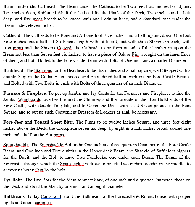
Good Evening Mark; Yes, you have read it correctly. The inboard length, which as you say is indeed called the cat-tail, is specified; the outboard length merely has to be 'sufficient'. The beam under this was normally called the cat-beam, and was the largest beam in the ship, bigger than the wing transom. If you need any other sections, let me know. All the best, Mark P
-
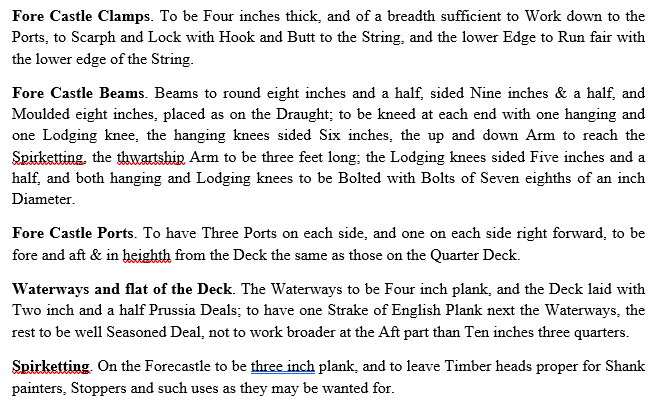
Good Afternoon Mark; If you don't already have this information, you may find the following extracts helpful with the timbering of the beakhead and forecastle. These are from the contract for Warspite, a 74, dated 1755, which I have transcribed. As the period is similar, the information is useful, and is more contemporary than the Shipbuilders' Repository, which is another source, very helpful, but 30 years later. All the best, Mark P
-
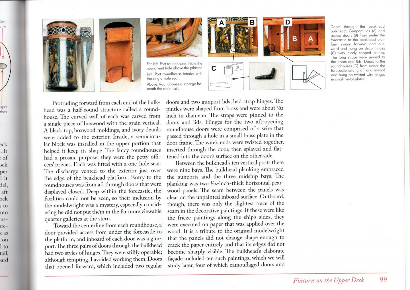
Good Evening Mark; Take a look at the pictures below, which come from Rob Napier's book about his repairs to the Princess Royal, published by Sea Watch books. This has a wealth of colour pictures of the internal features which are normally almost unseen. These show some good views of the roundhouse on this model. The doors are much narrower, and parallel sided. All the best, Mark P
-
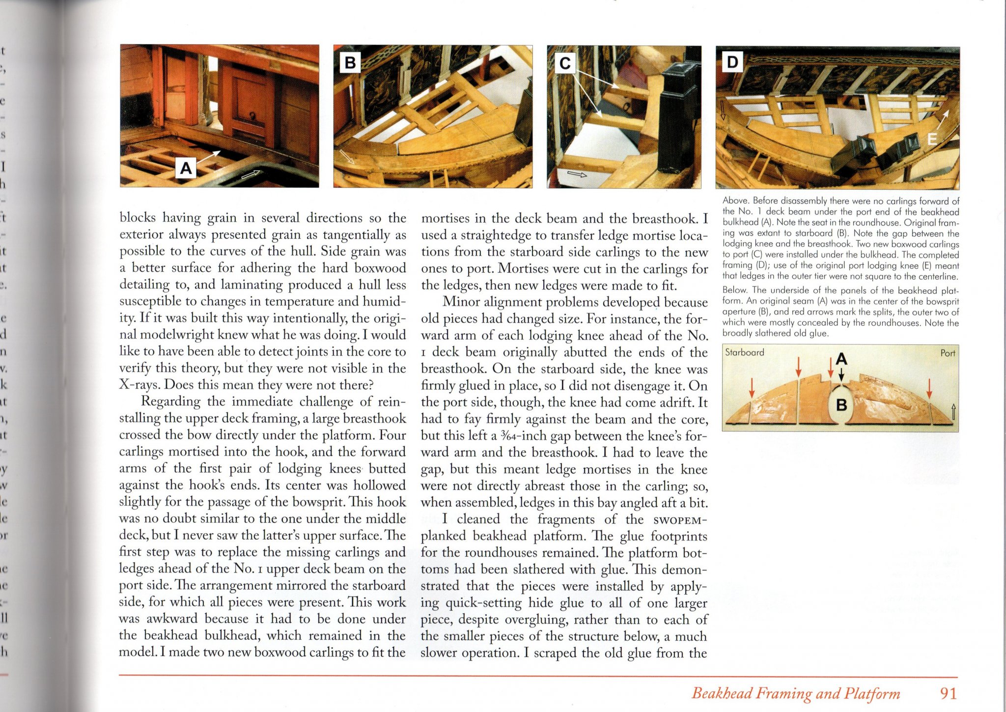
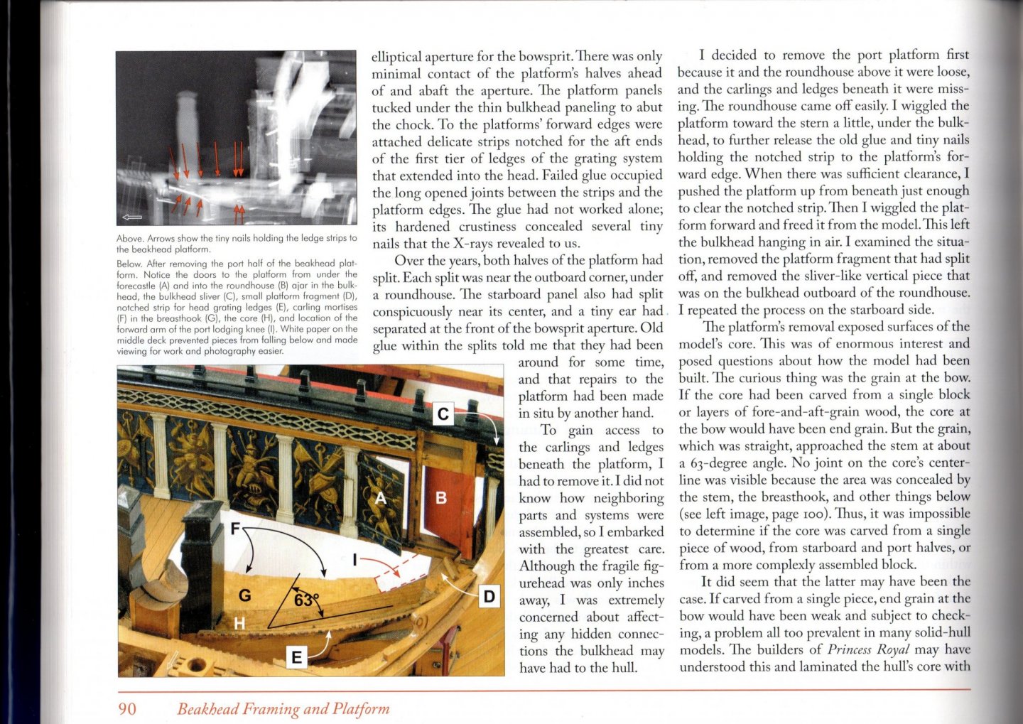
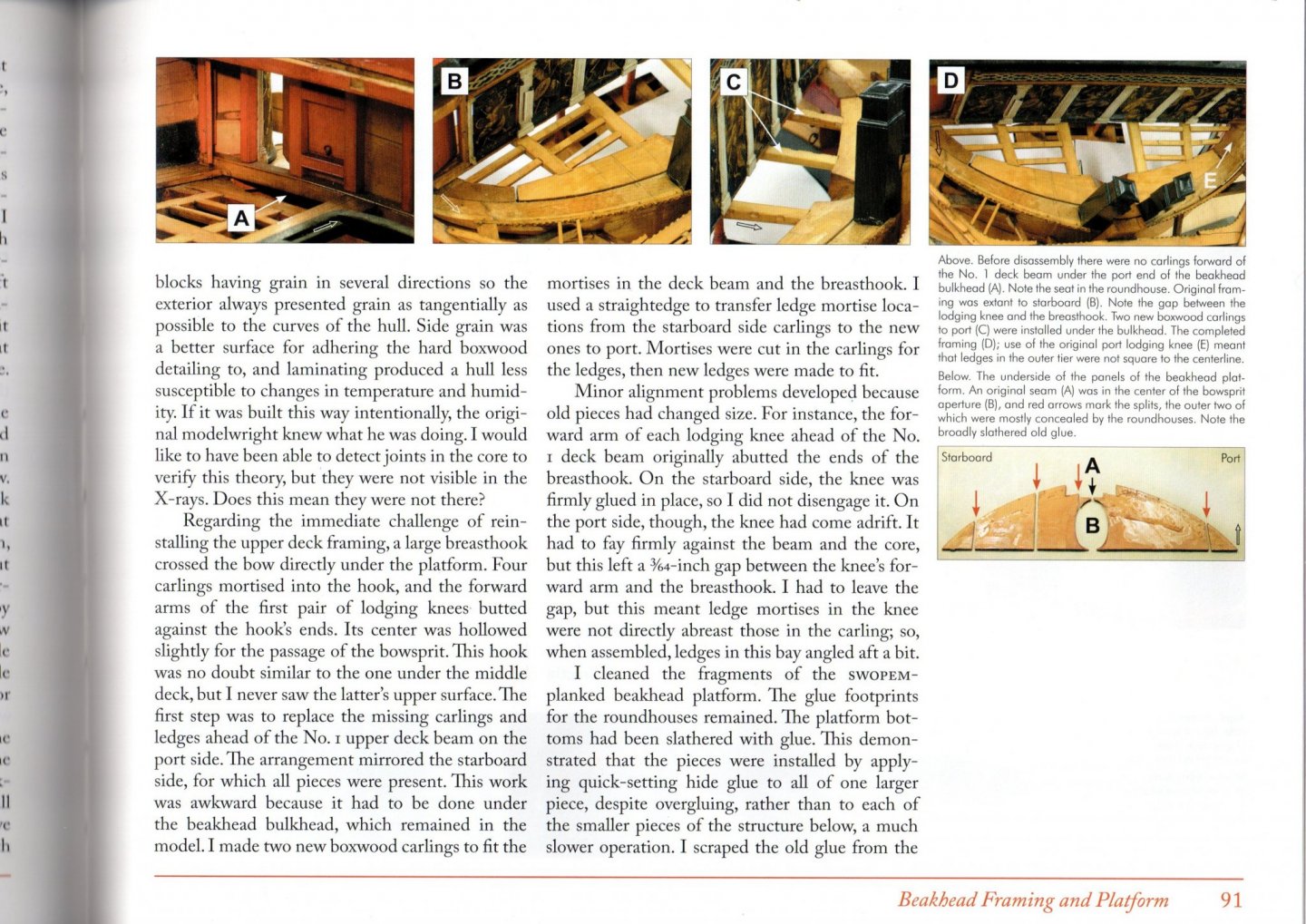
Good Afternoon Mark; Do you have Rob Napier's book 'Legacy of a ship model', about the repair of the Princess Royal in the Annapolis Collection. This shows many pictures of the inside parts of a model which one normally cannot see. If you have got this, look at chapter 6, pages 90, 91, 92, 98 & 99. There are lots of lovely pictures of the roundhouse from in and out, and removed; showing its internal structure quite clearly. It also shows quite clearly that there was a door in the bulkhead, to give the petty officers some privacy. As she was a 3-decker, the prow deck is not such a step up, so presumably on a 2-decker one had to duck carefully to squeeze in. The seat would have been higher than you show, as the deck of the prow deck formed the floor of the roundhouse. All the best, Mark
-
Good Morning Gentlemen; Further to the above comments, and as Bob says above, the garboard is often shown in sections as thicker than other planks at the edge where it meets the keel, tapering off at the outer/upper edge. In the 17th century it was also common practice to have thicker planks at the turn of the bilge. This was because of the need to grave, or clean, the ship's bottom, ideally twice a year; and to do this she had to be beached and allowed to lie on her keel and bilge. However this would be undetectable on a model. Sir Henry Manwayring, an experienced sailor who distributed one or two copies of his Seamans' Dictionary to influential patrons every year, around the 1630s, wrote that to spring a leak at the garboard was the worst disaster of its kind, 'as it cannot be got at'. It would therefore seem reasonable to suppose that the garboard received special attention. Another factor is that the timber shortages of later centuries would not have affected the shipwrights building the Great Harry, so wide planks would have been fairly easy to obtain. All the best, Mark
-
Good Evening Gary; She's coming on very well. Concerning the bolsters overhanging the cheeks, I have also seen the same instruction in several contracts. From what I remember, they always said 3/4 ", never 1 3/4" But you and the others who mentioned this are right, I would say: it does look better set back slightly, and that is the most likely reason for it being that way on models. All the best to you, Mark P