HOLIDAY DONATION DRIVE - SUPPORT MSW - DO YOUR PART TO KEEP THIS GREAT FORUM GOING! (Only 51 donations so far out of 49,000 members - C'mon guys!)
×


Mark P
-
Posts
1,772 -
Joined
-
Last visited
Content Type
Profiles
Forums
Gallery
Events
Everything posted by Mark P
-
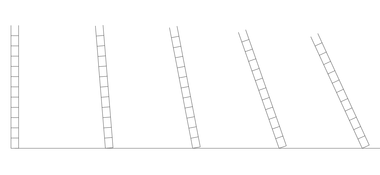
 Good Evening Mark; For tapering deck planks, take a look at my suggested method below. This will set them out nicely for you. Best drawn on a plan of the deck. Very simple, just an equally divided bar scale, rotated a little more each time as you approach the bow or stern. Then draw a gentle curve through all the left hand points, or bend the plank slightly to fit, if it will do so without buckling. All the best, Mark
-
Good Afternoon Messis; It looks to me as if it is the same sails in both pictures, but in the second one, the outer sail has been hauled further out on the jib-boom. It also looks to me as though the ship only has a bowsprit and jib-boom, there is no flying jib-boom rigged. So there are probably only intended to be two headsails in the present rigging set-up. All the best, Mark P
-
Good Morning Gerard; If you mean the projections at the bottom, the heel, this is due to the frames not being square to the line of the keel, but canted forward, so the heel has to be angled to fit against the side of the keel. If you mean the projections at the sides, this is simply because one half of the frame, the aft portion, one half of the frame sandwich, is much wider than the forward part of the frame, the other part of the sandwich. This is due to the taper of the ship towards the bow. Canting the frames negates some of the taper, but not all of it. All the best, Mark P
-
Good Morning Gerard; The frames are centred on the station lines because this is the joint line between two separate frames which make a sandwich, with the joints in each slice of the sandwich being staggered. The shaded area would seem to be the edge of that part of the frame which lies on one side of the joint line, and the un-shaded area is the edge of the other half of the frame. For example, in frame 5, the shaded portion each side is a single, un-jointed piece of timber, whereas the un-shaded part of the frame is in two pieces each side, and lies behind the shaded part. The joint line is shown dashed because it is hidden. Both halves of the sandwich have an almost equal amount of bevel. It also appears that one half of the sandwich stops at a lower height than the other, presumably around deck beam level. All the best, Mark P
-
Good Morning Alan; The confusion arises because when the bowsprit of Navy ships was first extended by adding an additional spar, this was frequently referred to as the flying jib-boom. So the combination was the bowsprit, and the flying jib-boom. There was no jib-boom. when the flying jib-boom proper was introduced, its end, as you say, was set in a cup in the cap, but it was secured with a lashing which passed through a hole in the heel of the flying jib-boom, and was given several turns around the jib-boom. I would say that Druxey is correct in the date for its introduction, although it may well have been fitted to frigates a little earlier. All the best, Mark P
-
Hi Fred; I agree with Chuck, it is looking good. However, one thing I can see is nagging at me a bit: are the timbers for the lower cills of the stern windows curving down at the outer end as they should? It might just be the photographs, but they look as though they are all in a straight line, whereas the bottoms of the windows should follow the curve of the upper counter moulding. Unless the timbers I am looking at are just infill pieces, there to help the ply facing piece take on the correct curvature, in which case please ignore my comment and carry on the good work. All the best, Mark P
-
Hello Mike; The black paint was official policy in the Navy, from around the 1780s I believe, although the custom was older. I cannot remember the reason, or the exact date. In 1740, Augustus Fitzroy, the captain of the Orford, wrote from Portsmouth harbour to the Navy Board, requesting them to instruct the port officers to paint the mastheads and yards of his ship black. In 1777, it was ordered that the lower masts of ships leaving to go to sea were to be painted. Unfortunately, no colour or material is specified. All the best, Mark P
-
Thanks for posting these Alan; Regarding the riggers hanging or drowning themselves, this was due to the Peace of Amiens, signed in 1802. Lord St Vincent, who had recently been made First Lord of the Admiralty, was convinced that the dockyards were staffed by rogues, who had no other object in life but to connive and steal for their own profit. As soon as peace was declared, one which St Vincent was adamant would last for at least 10 years, he immediately set up commissions of inquiry, and ordered swingeing cuts to the dockyard staff and Navy budget. He ordered halts to the purchase and stockpiling of most items needed for building or maintaining ships. These policies were opposed by more strategically aware Naval officers, but their protests were un-heeded. So of course, when war with France broke out again within a year or so, the Navy had few ships ready for sea, no timber stockpiled in the dockyards, a greatly reduced number of skilled men to put ships in commission and start on the building of new ones, and greatly reduced morale. At the same time, Napoleon was massing troops on the Channel coast, and proclaiming the forthcoming invasion of Britain. It was just like the disarmament policies of the British government in the 1930s, and the Munich agreement. Put not your faith in the promises of dictators! St Vincent, a notedly harsh disciplinarian even in an age when much that would be unthinkable now was regarded as commonplace, would certainly not have spared a thought for either the damage he did to the Navy, nor for the lives of those who were so badly affected by his mis-timed and inappropriate cutbacks. Many of these men were probably owed years of back-pay, and having been dismissed from their employment, would have been unable to obtain any further credit to buy food. Being unable to sustain their existence any longer, they probably saw no hope of ever receiving their arrears of pay, and quite understandably, just gave up. Sobering stuff. May their souls rest in peace All the best, Mark P
-
Good Evening All; Regarding the post with zu Mondfeldt's drawings of fish davits, his English style is not correct. The English fish davit was similar to the continental one he shows, and was, as mentioned in the extract from Lees quoted above, less than the overall breadth of the ship. It was used by having one end set in the span-shackle near the centre line, with the other end protruding over the bulwark. Regarding belaying pins, I would err on the side of caution when using Lees as an authority on this subject. His book is largely based on his own experience, admittedly a long one, of models in the NMM's collection. Whether he ever read Manwayring's book with his early 17th century reference to belaying pins (which is seemingly applicable to all sizes of vessel) or knew that they are mentioned in mid-seventeenth century contracts for two decked warships, must be doubted. All the best, Mark P
-
Good Afternoon Phil; Regarding the fish davit etc, it is possible that you are confusing the cat head and the fish davit (apologies if you are not!) In the Royal Navy, the cat heads were the outboard ends of a long beam (made in two pieces) which spanned the entire forecastle at the beakhead bulkhead, in each outboard end of which were sheaves used with a tackle (the cat-block and falls) to raise the anchor, once the men on the capstan had raised it as high as they could by hauling on the anchor cable. Hauling on the falls of the cat-block raised the anchor as close to the cat-head as possible/necessary, although it was still hanging vertically. The fish davit was then used, with another tackle, to haul up the crown (the point where the curved arms joined the vertical shank) of the anchor, from vertical, to horizontal, so that it could be lashed in the fore chains. The fish davit in Allan's picture had one end fitted into a square shackle, well fixed through the forecastle and upper-deck beams. In around the mid 1780s, the long fish davit was replaced by shorter ones which were set in a cast iron shoe in the fore channels. Regarding the date of the model, I believe that all of the models of sailing warships in the collection are contemporary, and so built at approximately the same time as the ships they portray. They were brought over from England in the early 20th century. Whilst this is a tragedy from the point of view of the English Museums' Collections, and the secretive way in which the models were sold and purchased aroused considerable controversy and condemnation at the time, I believe that it has had a good outcome. This is that the models are still on display (as so few now are in England, although that has improved slightly in recent years) that they are well-cared-for; and that being able to see them has undoubtedly made a considerable contribution towards the number of ship modellers in the US (and Canada) If the model has not been given a name, it is because it cannot be reliably identified with a particular vessel, only by period and type. Grant Walker and Seawatch books have produced 2 excellent books on the first and second rate, and the third rate, models in the collection, which are well worth looking at if you can purchase or find a copy. Regarding the introduction of belaying pins, see my first post in this thread, and several subsequent ones, which discuss the earliest known dates. All the best, Mark P
-
Good Afternoon Allan; Don't take it too hard, please. We are all guilty of making assumptions without making a proper scrutiny. I just wish it was possible to be certain about the origin of those belaying pins. There are apparently some photographs taken by R C Anderson, before the collection was sold, and one of these might show the beakhead as it was then. I just need to track down the pictures. As some of them are shown in Grant Walker's book, the location may be given in there. All the best, Mark
-
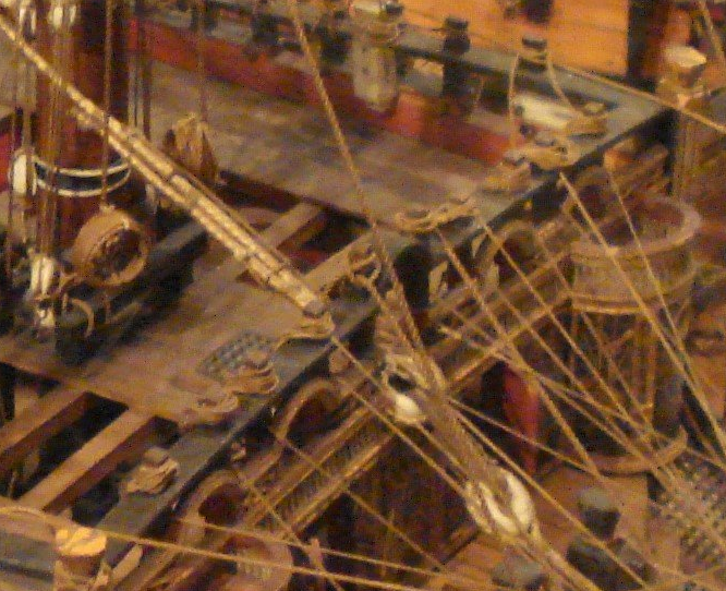
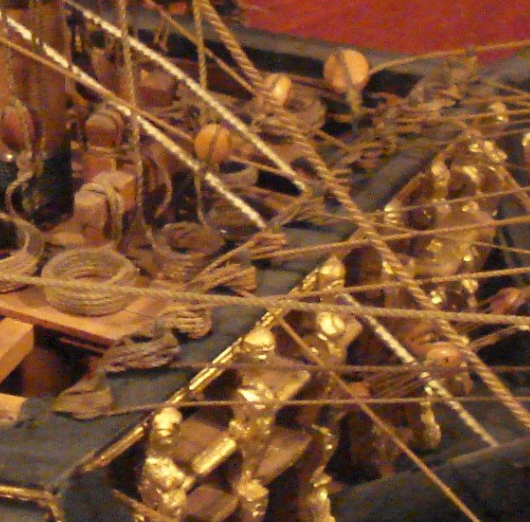
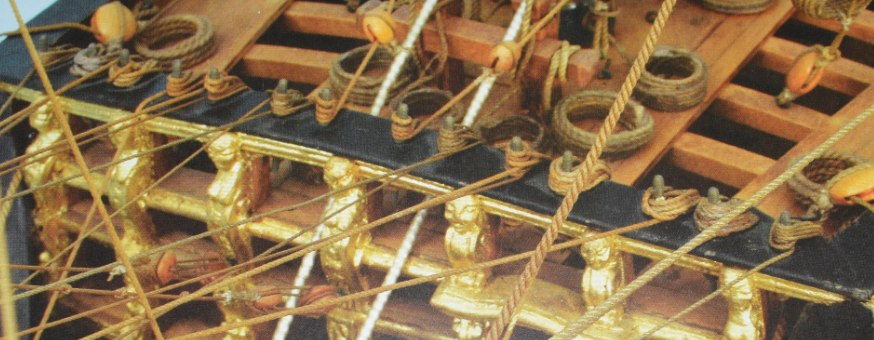
Good Evening Allan; I fear you are doing Phil an injustice. Those are quite definitely belaying pins in the fife rail of the last photograph. Compare the two shots below, from your third photo (to the left), and the last picture (right) They are noticeably different. Thank you for posting them, as I have not seen a picture of a beakhead with all pins in it before, and this is definitely worth seeing. I have just looked at the second volume of Grant Walker's/Seawatch's series on the Rogers Collection, and on page 11 there is a larger, clearer picture of the last model. It is even clearer there that these are belaying pins. See the picture below. The only doubt about these must be the suspicion that they might just have been fitted by Henry Culver, although as he was presumably also familiar with the model in your second picture, which shows the headsail ropes just wrapped around the fife rail, he would presumably have done this in preference to drilling and inserting a row of belaying pins. The same article in the book reveals that the model was rigged already in 1912, but the rigging was 18th century style, along with a lot of poor quality work to the hull, which Culver justifiably removed. So the rigging is presumably all by Henry Culver. All the best, Mark P
-
Good Evening Everyone; Druxey's comment seems fair enough, looking at the rather pristine state of the ropes, and the lack of dust anywhere. Henry Culver did a lot of restoration/reconstruction work to the Colonel's models, but surely even he would not have gone so far as to insert a line of belaying pins along the fife rail. So presumably the pins are genuine, even if the ropes belayed to them are not. All the best, Mark P
-
Good Morning All; Thanks for all the thoughts set out above. All very interesting and thought-provoking. I used an air brush with some model painting acrylic paints bought in a High Street bargain store. I thinned the paint with water, and after two coats the colour was deep and solid. However, this was on un-sealed lime wood, which is very porous. I wonder what the results would be on boxwood, which is much less open. I will have to try an experiment. All the best, Mark P
-
Thanks for those Alan; One of the reasons why shipwrights remained at the Royal dockyards, rather than seeking the more highly-paid and sooner-received wages for work in the merchant yards (dockyard wages could be four years in arrears) was that there was a chance of retirement and a pension, if one's service was thought worthy of it, once work became too hard. The same applied to the warrant officers serving on sailing ships. Greenwich Hospital also took in distressed sailors in old age, who had no other resources. This all dates back for at least three hundred years. In a time when life was precarious and hard for so many, any chance of some assistance in old age was greatly valued. The Navy was more paternalistic than popular modern legend, obsessed with flogging and sodomy (not necessarily at the same time) would have us believe. One reason for Nelson's success as a commanding officer was that he cared deeply for all his men's welfare, and tried hard to make some difference wherever he saw the need. He saw command as carrying an obligation towards those commanded, and not just as a means to personal glory or success. Not all saw things in this way, of course (and still don't!) All the best, Mark P
-
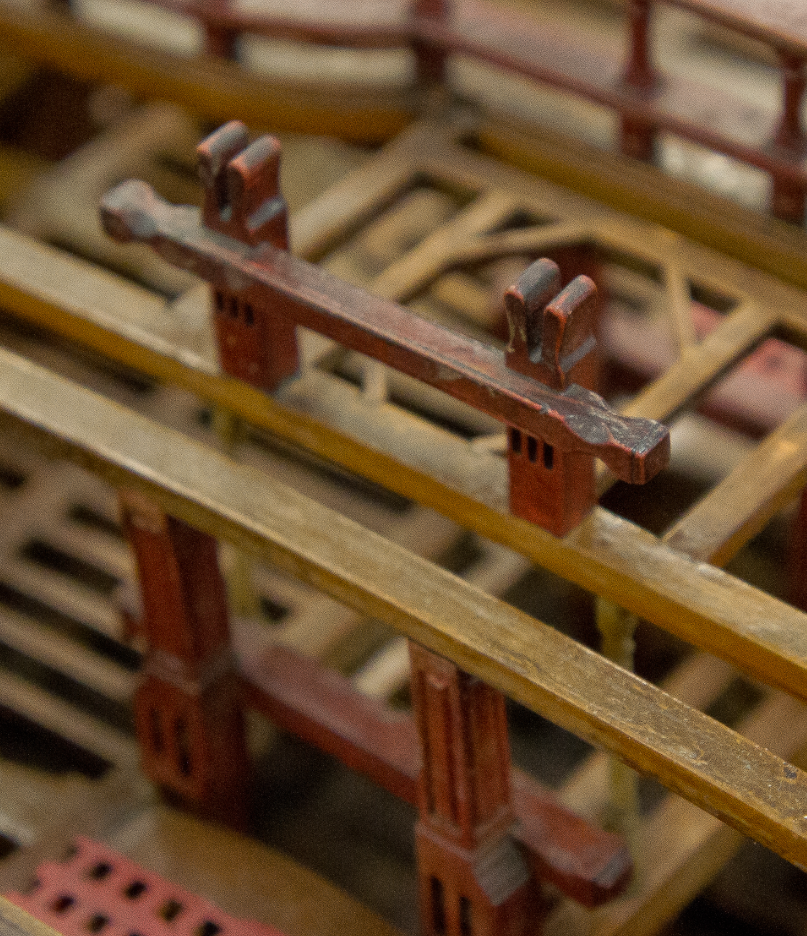
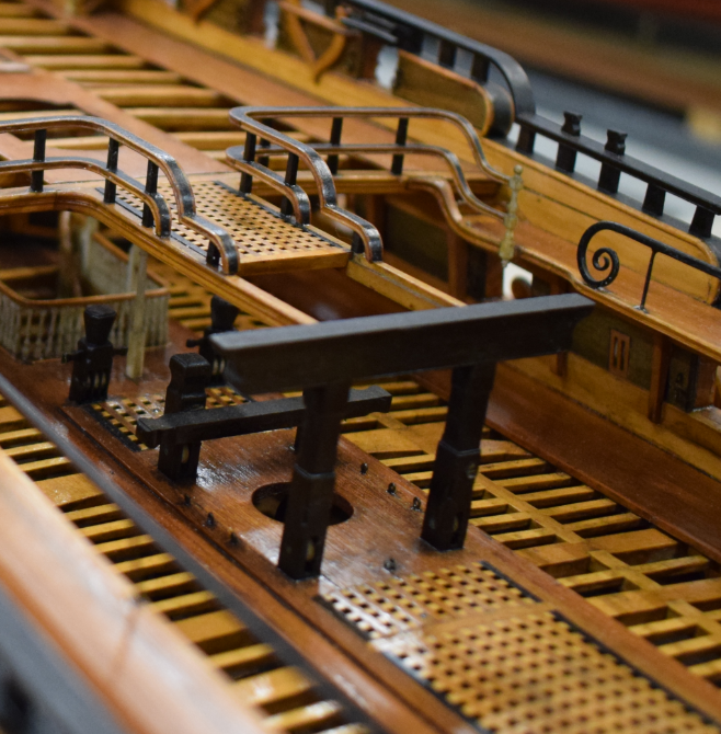
Good Morning Pat; I can help with some of your questions, but this is somewhat outside the period I know best. My answers are general, not specific to the particular vessel you are modelling. 3. The part of the bitts below deck was frequently tapered, and became noticeably thinner in a fore and aft direction by the time they reached the deck beams below. 4. The gallows was fitted to extended topsail sheet bitts, being around 5'6" - 6' high to the underside. The crossbeam on the top extended beyond the bitt pins. It was frequently used either to support a walkway projecting forward from the quarterdeck, or the spare spars for the ship. I have never seen a gallows referred to in any context but as an extended set of bitts with a high-level crossbeam. See below for an example of 'horned' bitts, from the framed model of Bellona, & an 18th century gallows from Royal William. The top surface follows the deck camber. All the best, Mark P
-
Is there a Beginner’s Guide to Metal Work?
Mark P replied to VTHokiEE's topic in Metal Work, Soldering and Metal Fittings
That's a bit of a pain; I purchased the first edition about a year ago. Now I will have to see if I can locate the second one! Thanks to all for the information in this very interesting and informative thread. All the best, Mark P -
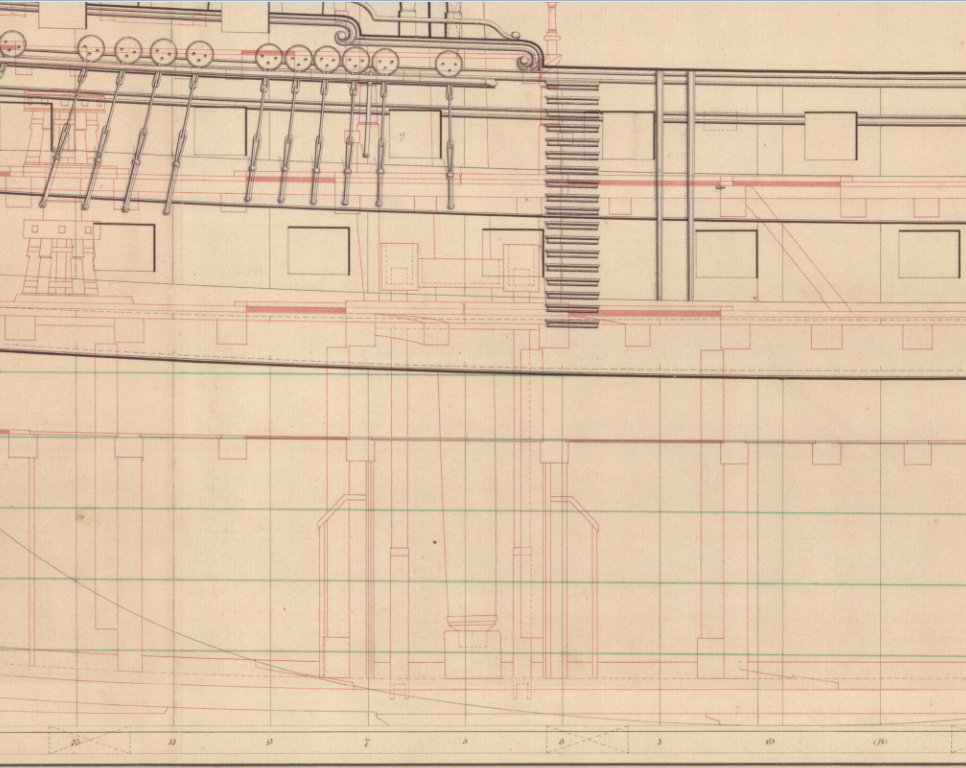
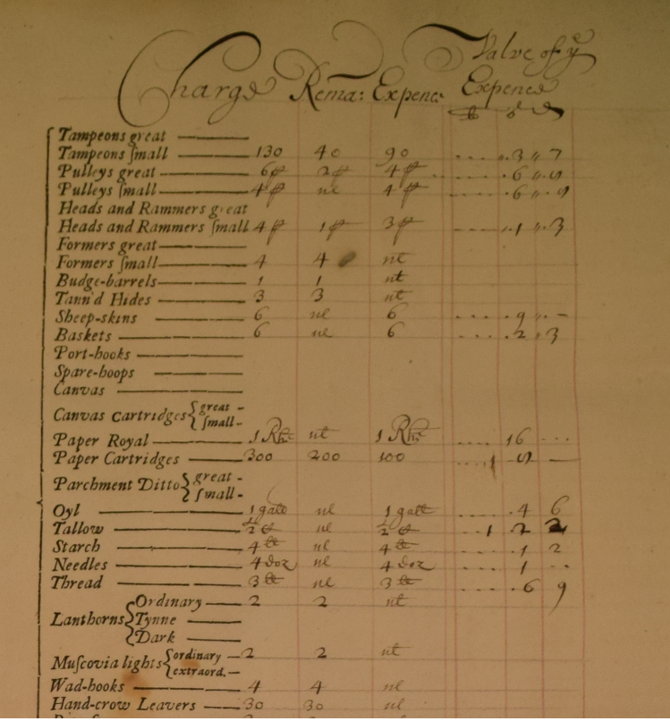
Good Morning All; The number of cannon-balls of each size was laid down in the Navy Board's standing orders, with quantities reduced for each smaller size of ship. When a ship was commissioned, the guns, powder and shot were all supplied by the Ordnance Board, and the ship's gunner had to check the quantity and was then responsible for all the stores issued. At the end of the commission, he had to account for, or return, everything which had been issued previously. As these stores were worth a lot of money, a strict inquiry was made for each ship. I have read of cases of powder being concealed behind piles of timber or under other stores in order to steal it (merchant ships or privateers were ready buyers) One ship, whose name I cannot remember, is believed to have been blown up when a stolen cache of powder was accidentally ignited. All the stores were listed and named on a printed sheet several pages long, with the quantities entered by hand. One document was created at issue, and then updated on return of the stores. See sample below, dating from 1682. Regarding the storage and movement of round-shot, the shot-lockers were located either side of the ship's well, directly under the successive layers of the main hatch and the after hatch on each deck. It would not have been difficult to rig a sling through either hatch and haul a net-full of shot up to whatever deck required it, which was the reverse of the method used when loading the round-shot from a delivery. Additionally, a quantity of shot was stored on each deck in racks, ready for use. The shot-lockers were divided internally to keep different sizes of shot separate. Each locker is approximately 9-10 feet tall, so they would have held a lot of shot. See below an excerpt from a draught of a 74, showing the hatchways (the solid red, horizontal rectangles) and shot-lockers in line. All the best, Mark P
-
Good Morning Gentlemen; A model with stylised frames would indeed be a good way of building a framed model in an instance where the true framing pattern is unknown, and would follow on from a long tradition. I would like to make one comment on the Navy Board pattern of framing models, though. Which is that the most common method of construction depicted in such models does actually represent a technique used in full-size practice in the early 1600s, and perhaps earlier, and was not as stylised as many authors have stated. Construction using interlocking timbers is documented archaeologically, and is specifically demanded in some early ship-building contracts. Interlocking floors and first futtocks continued into the early 1700s in some instances. A frame produced using interlocking timbers is actually very strong structurally, but was discontinued, I believe, for three reasons: firstly, the need to use relatively thick futtocks to maintain contact between adjacent timbers, which became harder to satisfy as timber shortages began to bite (this is already being complained of in the mid 1600s) Secondly, the fact that the relatively large spaces between the timbers (outside the areas of interlocking, which were obviously very strong) provided no protection against cannon-shot penetrating the ships' hulls. Lastly, the close contact between timbers encouraged dampness, which led to the onset of rot. All the best, Mark P
-
Good Evening Wayne; Your questions raise a good point. But if there are no records of how merchant vessels were built in this period and location, who can say what methods and sizes of timber were used. Archaeology may have some good indications, certainly, as Roger mentions. Where the local shipwrights were likely to have been trained would give some indication also. On Bermuda? If most were immigrants, they would bring their own traditions. I was looking at an original copy of the 'Shipbuilder's Repository' only a few days ago, and the unknown (but very knowledgeable) author included a section on the scantlings of merchant vessels. Unfortunately I did not photograph this part, as I concentrate on warships, but the author's opening remarks to this section indicated that merchant scantlings could be heavier than those of Navy vessels. This seems counter-intuitive, and as I only skimmed it briefly I may have not really taken it all in, but I am sure that this was the import of his remarks. If anyone reading this has a copy of the Repository (which is a very informative and information-packed volume) maybe they could check the beginning of the merchant vessel section and confirm/correct my impression, and expand on what is said there. The book was published in 1788, so will relate to ships somewhat earlier than this date. Yet whatever is said there is still not provably relevant to Bermuda, as you say. In the absence of any firm evidence, all that can be done is to choose one of a variety of options, and stick to it. In which case, it is probably best to choose one which is not only a possible method, but one which is fairly-well documented to avoid too much guesswork being needed. All the best, Mark P
-
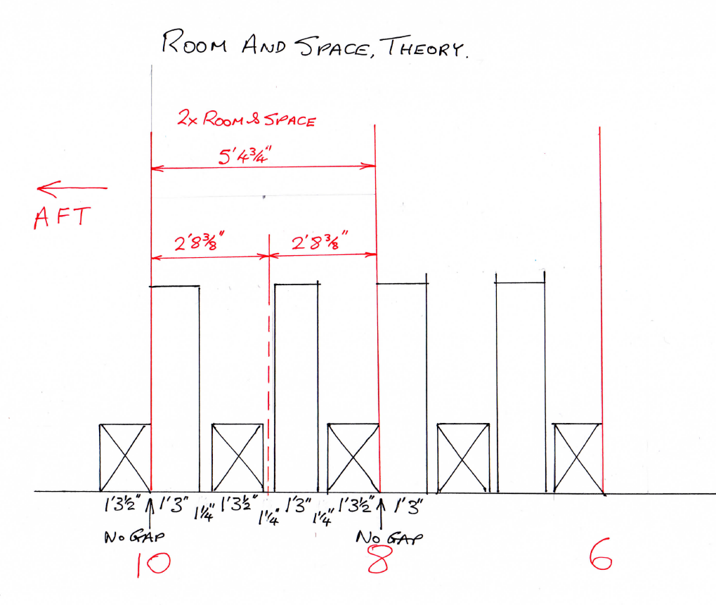
To clarify Jaager's post above, see below a sketch I made to illustrate room and space. This is based on a distance of 2'8 3/8", the room & space for a 74 gun ship, Ganges, and shows the station lines at 10, 8 & 6, at each of which there would be a double frame, or 'bend' located. Between these station lines lie 2 filling frames, which, being single, are not bends. The exact spacing of the filling frames could vary relative to each other. Note that other patterns of framing were used, but this will help to understand how it works. All the best, Mark P
-
Good Morning Gerard; As Mark says above, commercial plans may give you the answers you want. If this does not work for Lexington, then you will have to calculate or locate the dimensions. There is some confusion in your post, in that you mention you are looking for moulded dimensions, but then state that this is between the fore and aft faces. Then you seem to correctly describe the sided dimension. So it appears that you are correct in knowing that you are looking for the moulded dimension, but this is the distance between the inboard and outboard faces of the futtocks etc. In the Royal Navy, where the most plentiful records survive, everything was proportional to one of the principal dimensions of the ship. Originally this used the length of the keel, but by the 18th century, the length of the gun-deck, ie the length between perpendiculars, was used. Every dimension in the ship was then calculated as a proportion of this. As gun-deck length was fairly standard within each class, both these systems led to a high degree of standardisation. As large numbers of the shipwrights working in the original colonies or other parts of the Americas would have been trained in England, it would seem a reasonable assumption that the early American vessels were built using the same or a similar system. If there is no known record of the moulded dimensions used for Lexington, or similar ships at the time, then to use the RN's system will certainly give a viable method, even if Lexington was originally built as a privateer, which I think is the case here. If you can locate a copy of a builder's contract for a Royal Navy brig of similar size, this would be a good source for moulded dimensions. Alternatively, Allan Yedlinsky has compiled a book of scantlings used in the Royal Navy, available from Seawatch. I am not sure if this covers ships with two masts, but Allan is a member of this website, and he will be able to confirm this for you. I would suggest sending him a personal message (he is here under his own name) as he may not see this post otherwise. Note that moulded dimensions normally reduced at several points going forward and aft, so they were not constant. All the best, Mark P
-
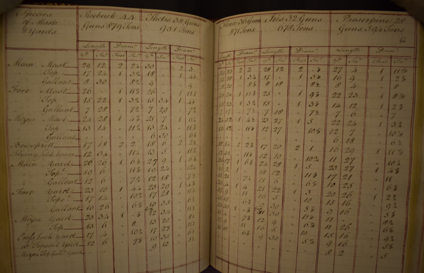
Good Evening Matrim; This might help you settle the sizes. See below an extract from a 1790 volume in the British Library. This gives mast & yard dimensions for a vessel of every class, including Iris, a 32 gun ship. The photograph is slightly out-of-focus as the reading rooms are not brightly lit, and the BL do not allow the use of camera stands, so everything is hand-held with an elongated exposure. The bowsprit is 52'8" (given as 17 yards & 20 inches) Note that the reference to 'flying jib-boom' is actually referring to the jib-boom. This was commonly called a flying jib-boom from its introduction in the early 18th century. If you need anything more, let me know. All the best, Mark P

-
Good Evening Auger; They would certainly have been notched out, as the iron bands were proud of the mast's surface. I know that I have seen this described somewhere, but I cannot remember where. Failure to do this would have allowed the battens to distort and crack under the localised pressure from the shrouds and other objects looped over the mast head. The lower part of the mast had its core bound together with iron bands, and the fishes and paunches applied over the bands were notched out to sit flush on the core. Incidentally, I see that you are using James Lees's book. Do not rely on his statement that iron bands are seldom seen on models before 1800 as a guide to full-size practice. After the American colonies became independent, the supply of New England masts dried up, and the Navy could not obtain trees of the same size elsewhere. The trees they formerly purchased from the colonies were large enough to supply most masts as a single tree. After the loss of this supply, they came to rely much more upon 'made' masts, comprising smaller pieces all carefully interlocked. These needed iron bands to hold the component parts together. From the late 1770s onward, there are a large number of drawings of masts made at various dockyards, all of 'made' masts, listing the sizes of the component timbers and their costs. These all show iron bands around the core, and each seems to be the relevant Master Shipwright's suggestion for overcoming the shortage of large trees (this is my assumption, and is not stated as such on any of the drawings) For any vessel built or re-masted from 1780 onwards, I would use metal hoops on the mast. All the best, Mark P
-
Good Morning Ferit; If you are talking of 18th century ships, or earlier, I have seen frequent mention in lists of bo'suns' stores to candles, and they are mentioned in other documents. Oil would be a volatile substance to have near a flame on a constantly-moving ship made of wood. I would exclude oil completely, and show candles. However, for 19th century merchant vessels, oil might have been used. I cannot say. If this is your area of interest, try looking under the National Maritime Museum's online collections site. They will certainly have some ships' lanterns there. All the best, Mark