


usedtosail
-
Posts
2,377 -
Joined
-
Last visited
Content Type
Profiles
Forums
Gallery
Events
Posts posted by usedtosail
-
-
Thanks guys. Every time I go to the dentist I think about looking into these, but with this information I can forget about it now. I bought a strong pair of readers that work really well for me better than the flip up magnifiers.
-
Thank you all for your encouragement. I wouldn't dream of tackling something this complex without knowing I can rely on you all for guidance and support.
I have been comparing the supplied plans with the AOS Constitution and started to note some of the differences, although the deck details in the AOS are not as detailed as I would like. I fear that I may end up adding details from the current configuration that weren't there in the 1812 version, but hopefully that won't happen too much.
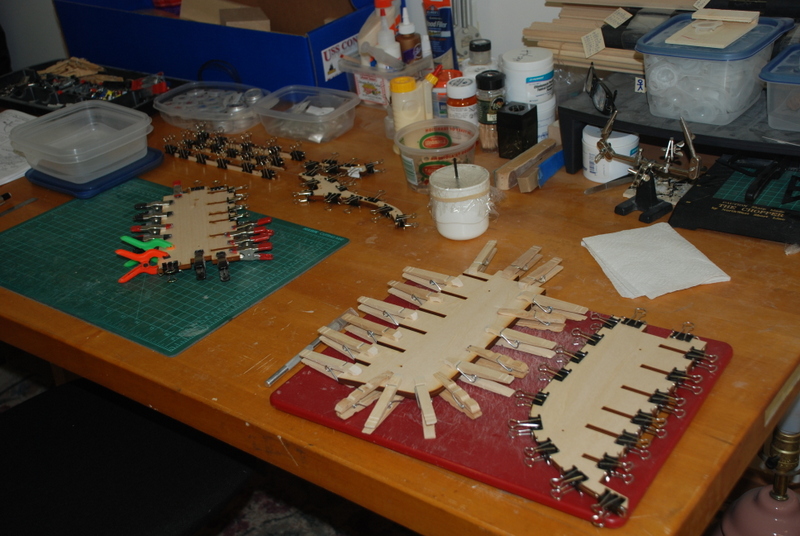
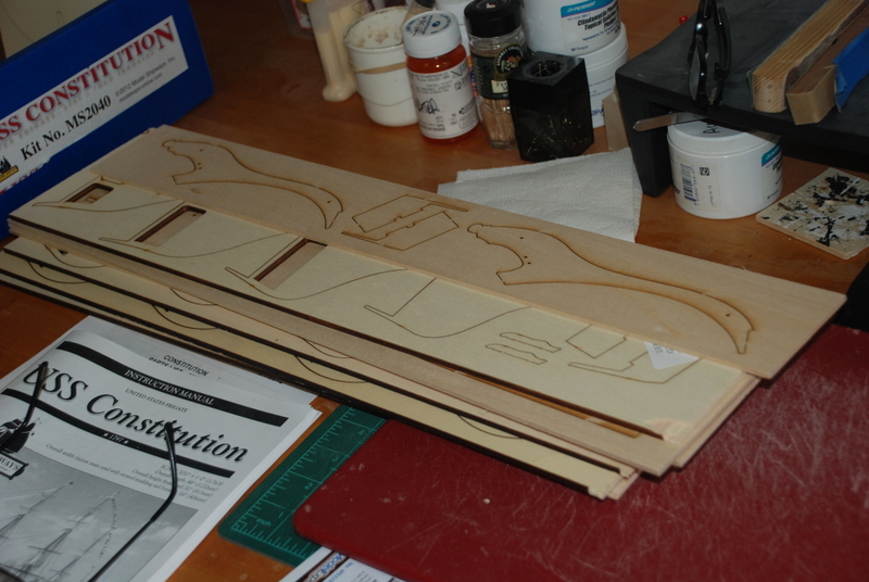
This week's progress. I cut the keel and stem pieces from the laser cut sheet and glued the halves together. I used just about all the clamps I had that would work on these pieces.

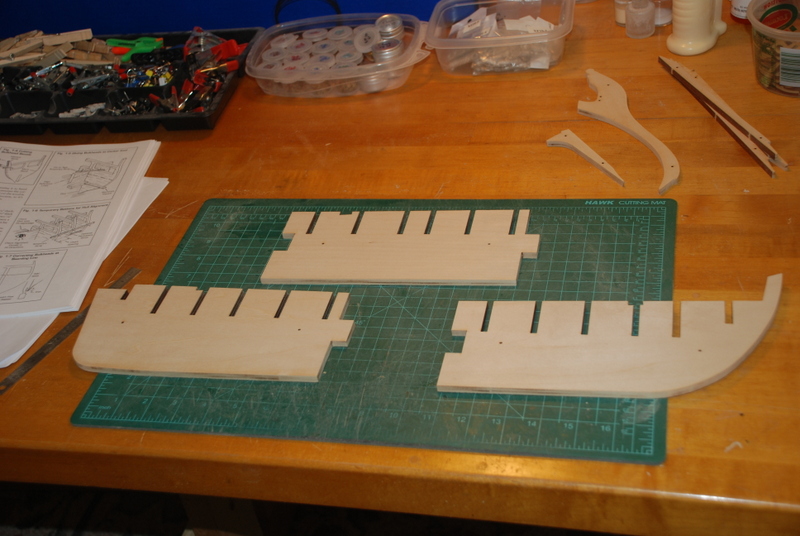
I then cleaned up the three keel former pieces and some of the other pieces. I used a sanding block on its side to keep the edges square. I have since ordered a True Sander to do this right, so I am waiting for that to arrive before cleaning the other keel pieces.

I copied the plans for the three keel former pieces and glued them to some manila folder material. I will use these to transfer the bearding and other reference lines to the wood.
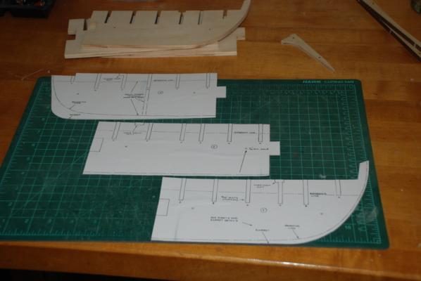
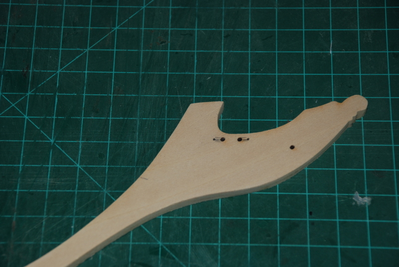
One difference between the 1812 version and the current version is that in 1812, the ship had rope gammoning, not chain as it does today. So, in order to use rope on the model, I need to expand the holes in the stem to slots. I have marked them on the stem but have not cut them out yet.
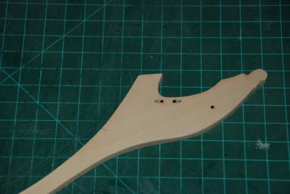
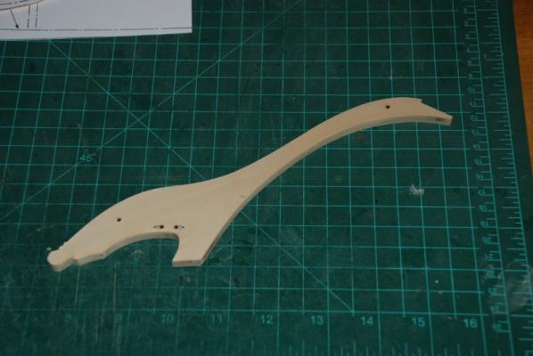
Here is my favorite picture of the stem - looks like a dinosaur to me

Thanks again for the encouragement and support.
-
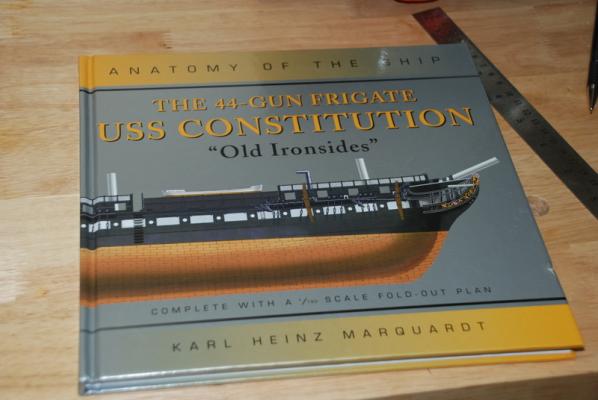
Besides the kit instructions, I plan to use the Anatomy of the Ship book for the Constitution as an additional guide. I used the AOS Beagle book to build that model and I really liked the extra information and details in these books.
I am going to try to build the Constitution in its 1812 configuration, as others have done on this site. In fact, those other build logs (Cookster, CaptainSteve, Jeff Toma, and others) have been a huge inspiration for me and I know the information in them will be a huge help.
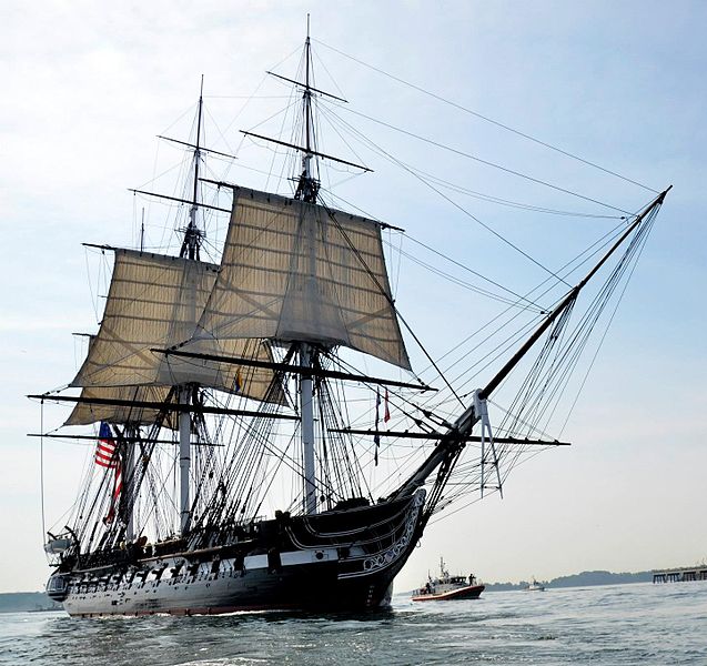
I plan to add some sails to the build, and my first thought was to go with a look like in this picture, when see sailed in Boston Harbor in August 2012 for the 1812 anniversary. I believe our own popeye2sea (Henry) was on it when this picture was taken.

Now I am thinking of adding some fore and aft sails too, but I am not sure on that yet.
-
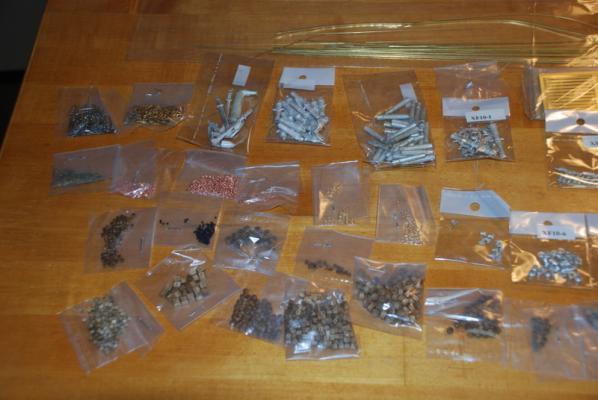
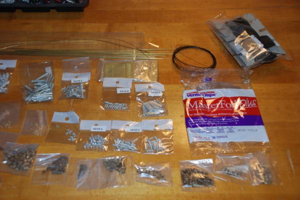
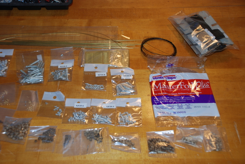
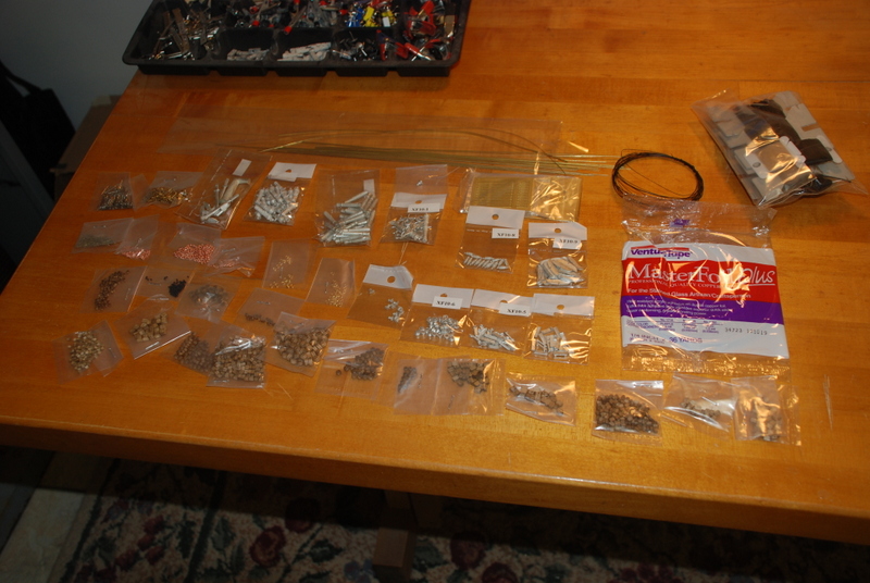
Some more content pictures:
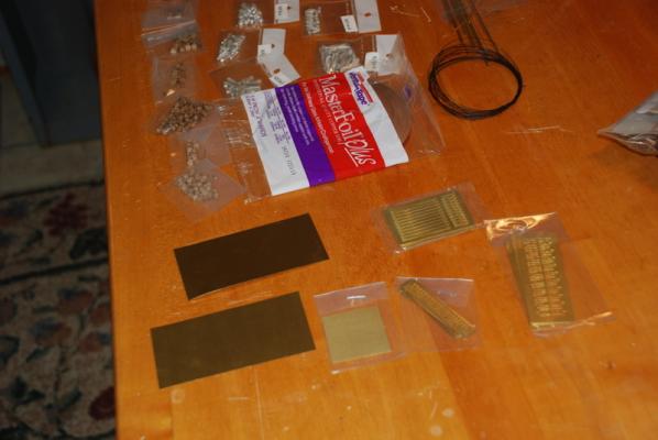
Some photo etched brass parts:
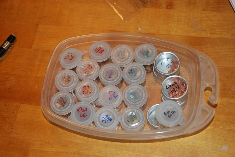
I organized the blocks, deadeyes, and bulls eyes in these small containers:

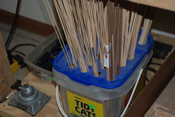
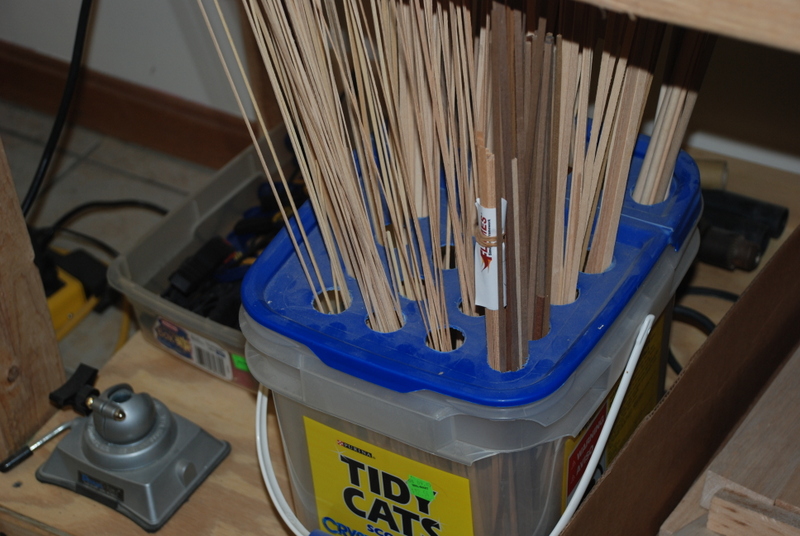
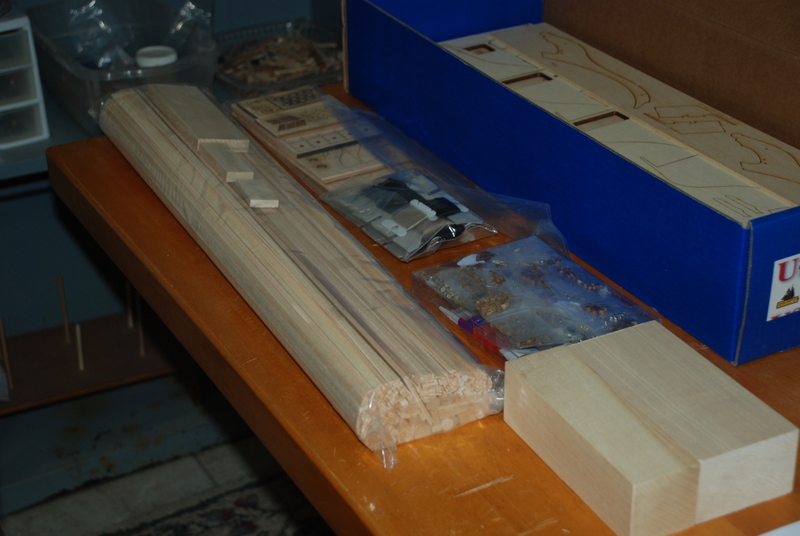
For the wood strips, I used these plastic golf bag tubes that I got from my father. I had originally planned to use these to organize all the extra wood strips I had in the workshop, but I had to go to something that could handle more strips, which you can see in the picture after this one. I was pretty amazed that the strips just in this kit filled up these tubes.
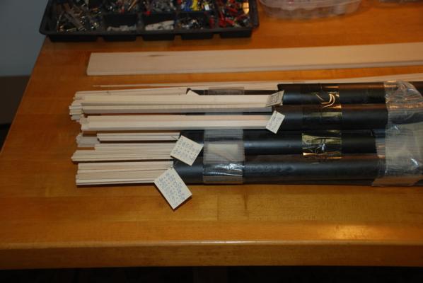
What I use now to organize my wood supply in the shop:
- Landlubber Mike, bbrockel, alde and 18 others
-
 21
21
-
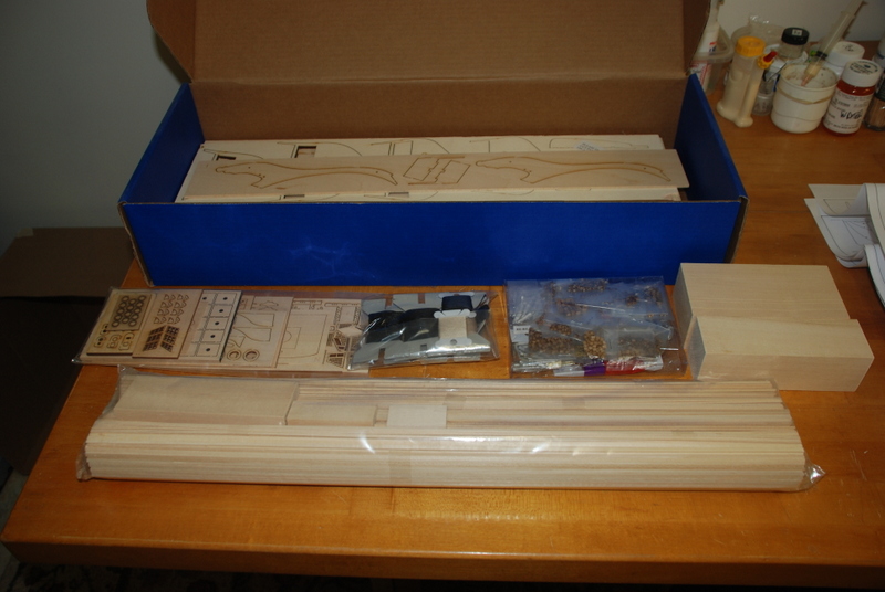
I am about to start the Model Expo Constitution. I have had the kit on the shelf for about a year, but I was waiting to finish the Bounty Launch. I only looked in the box once since I received it, and did not realize how many pieces parts there are for this one. I have to say I am a little intimidated now that I have started going through everything. Well, here goes...
Before I get to the pictures, I have come back to add an Index to this build log.
Hull Construction:
Deck Details:
Gun Deck Chain Pumps, Stove, Riding Bitts
Masts and Rigging:
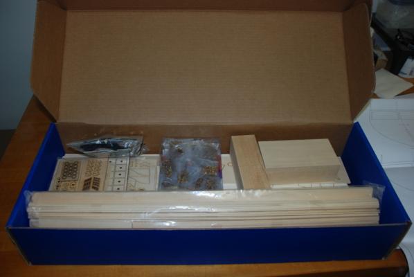
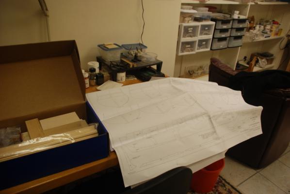
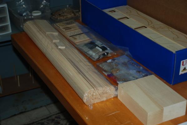
Now, some pictures of the contents:
Eight pages of plans:
A lot of wood pieces:


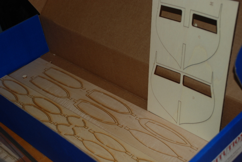
Looks like they upgraded some older parts:

Copper foil for the hull, blocks, cast metal parts, etc:

-
Flaws? What flaws? I don't see any. The detail you have added to these boats is incredible.
- GLakie and CaptainSteve
-
2
-
Those treenails are sweet. I like the color differences of the wood on the interior, too.
-
Thanks Bedford. I have not started the Constitution yet. I have a little more research to do first. I'll start a build log for it when I get going on it.
-
Mick, I will be very interested to see the differences too.
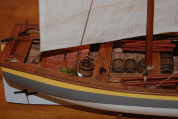
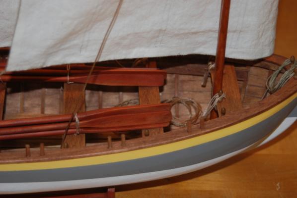
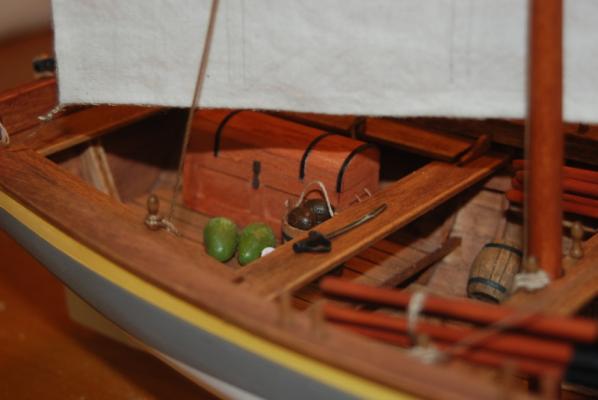
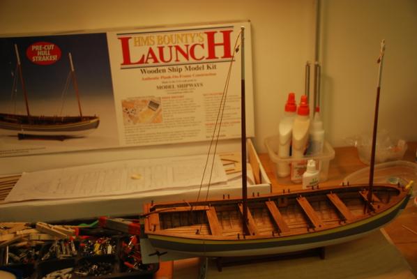
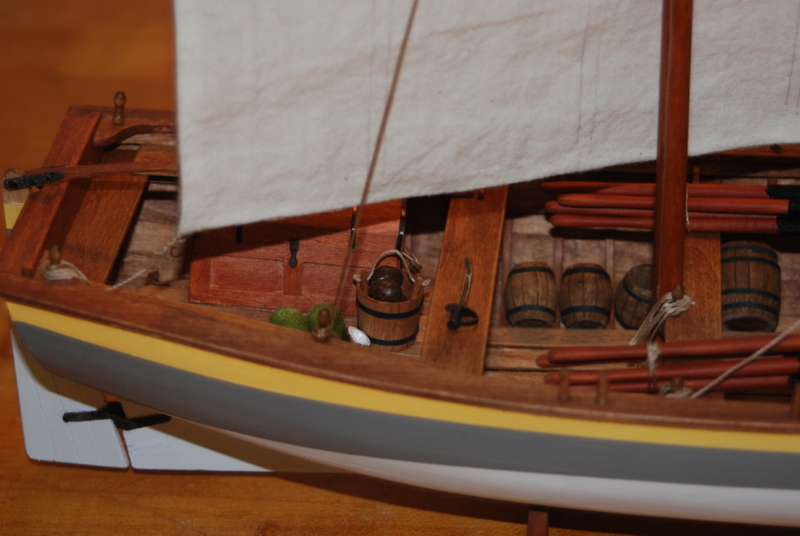
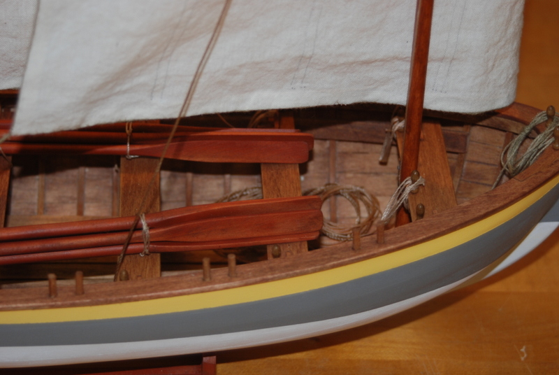
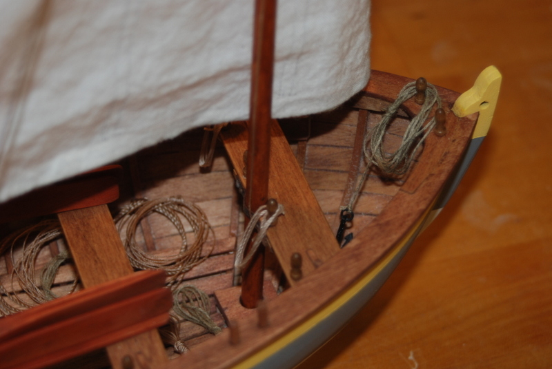
Well, how is this for timing. I finished the Bounty Launch on the last day of the year. I tied two bundles of oars together and tied them to the thwarts. I added the toolbox, bucket, coconuts, cutlass, barrels, coils of rope, and the grapnel, then took these pictures. Enjoy.


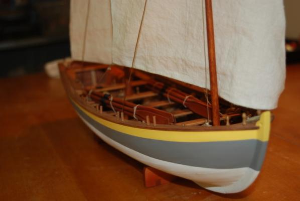
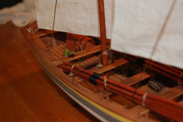

I will take some proper pictures soon and add them to the gallery.
This will conclude this build log. I hope I was able to convey some ideas for others to try. I had a lot of fun with this build and I am looking forward to the Conny, which I will start soon.
I hope you all have a great New Year. Thanks for looking in.
-
Thanks Greg. I am too.
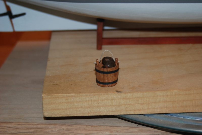
I couldn't leave the bucket unfinished, so here it is with its new bands.

I feel better now.
-
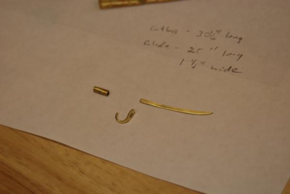
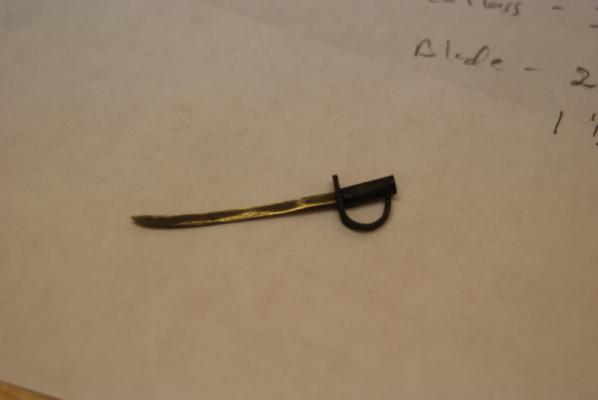
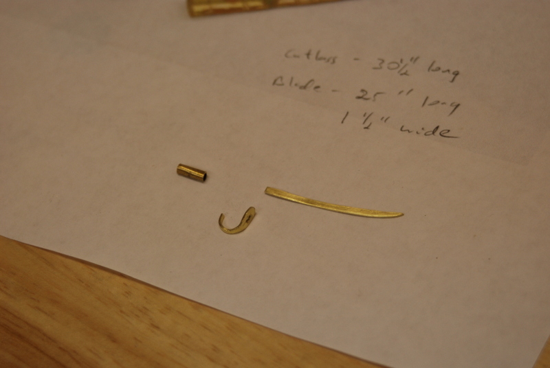
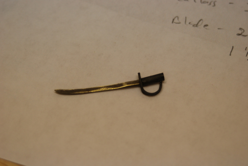
I made a few items to enhance the boat contents over the kit supplied items. I made a bucket by turning a piece of dowel on the lathe. For the slates, I used the same technique I used for the barrels, scoring the lines using a razor saw. I added a handle and filled it with some husked coconuts I made from Sculpey. I also made some unhusked coconuts from Sculpey and a halved one. I made the cutlass from some brass strip and a small piece of brass tubing. I used a wide piece for both the blade and the handle. On the blade, I filed in the curves. I used a single piece for the handle. I first filed in the shape of the hand guard, then filed the rest narrower and bent it around for the finger guard. I blackened the individual pieces, then glued them together with CA. I filled in the end of the handle with wood filler, then painted the handle black. I lightly sanded the blade so some of the metal shown through. I still have to add the bands around the bucket, which I will do with black paper.
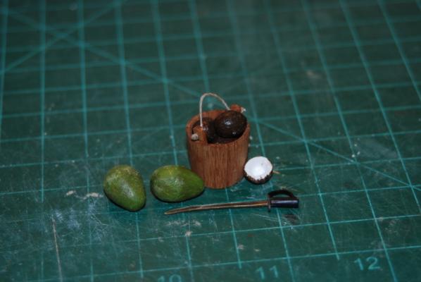
I really enjoy making these extra little details. Now I just have to figure out how to put all the stuff into the boat so it looks right.
- captainbob, rlb, CaptainSteve and 1 other
-
4
-
Keith,
You are off to a great start. That bending method you came up with is pretty neat. I am looking forward to following your build.
-
Thanks Pete and Richard.
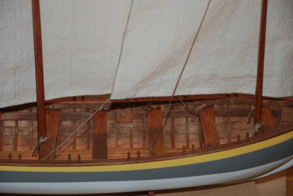
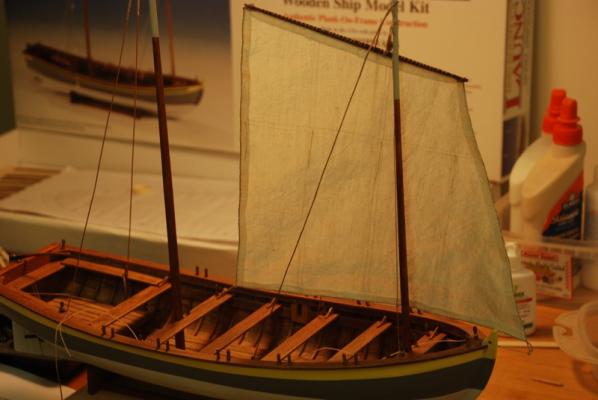
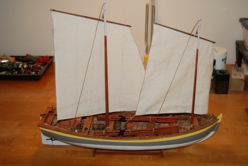
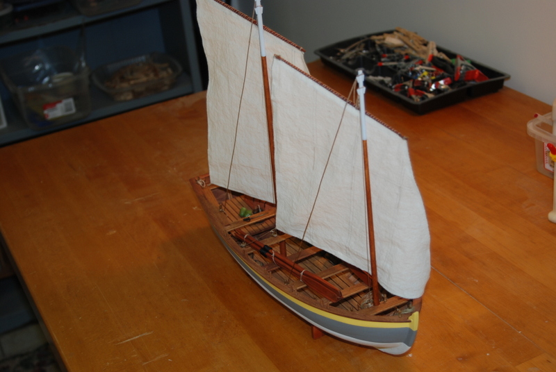
Here are the pictures with the main sail attached and all the rope coils installed.

I hope everyone got what they asked for this Christmas. I am looking forward to spending the rest of the day with my family.
-
The main sail is compete and I added it to the model this afternoon. Pictures to follow. I did get an early Christmas present, though, so I used it to take the following pictures. It is a macro lens for my camera, so now I can get all those too close shots that show off all the flaws
Merry Christmas everyone.
-
Thanks Mike. One of the plan sheets showed the sails on the spar on the boat, but they were shown in profile, so I traced the outline from that. It also showed the seams and the reef points (the ropes that hold the furled sails), so everything was there that I needed to make them. It did not show any holes along the top of the sail, so I just used a needle and sewed it to the spar.
-
Thank you Steve. I wasn't sure when I started this that it was going to be as interesting as the larger builds, but I have learned a lot and really enjoyed it. Plus my wife will be happy that we can put this on our mantle instead of taking a large space somewhere else.
-
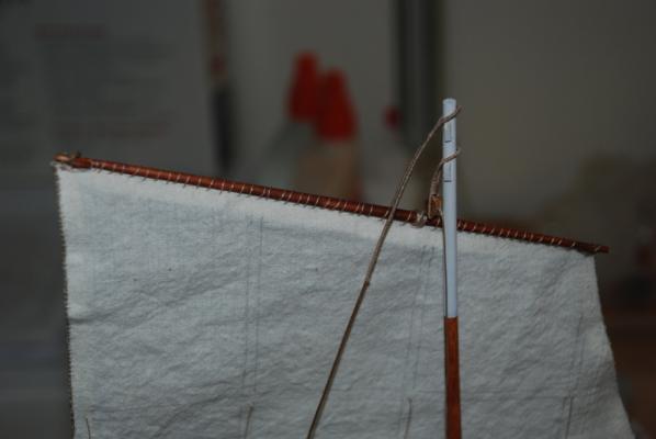
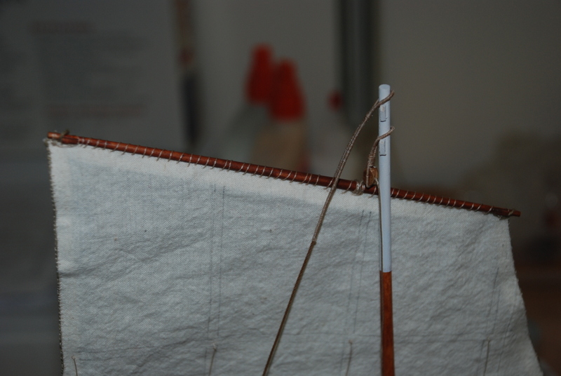
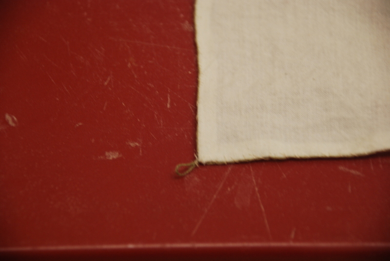
And here is what I have been working on all weekend, the fore sail. I used Tacky Glue to glue the seams all the way around the sail, cutting the corners so the material from two sides did not overlap. I then sewed a bolt rope all the way around the sail, seizing the corners into loops as I got to them. I started at the middle of the head of the sail and worked my way around. I used a very thin needle so the holes in the sail were small, and just went through the sail and the bolt rope at the same time, looping around each time. I finished where I started and trimmed the bolt rope so the ends were flush.
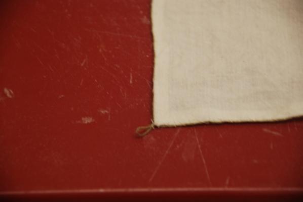
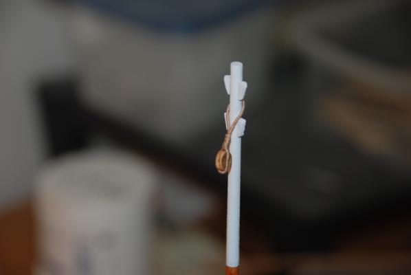
Here is a close up of one of the loops and the bolt rope on either side.
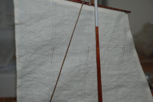
I drew the other seam lines onto both sides of the sail using a regular pencil with a light pressure. I added the reef points by knotting a piece of line and threading it through the sail with a needle, then tying another knot on the other side close to the sail. I left these all long until they were all on, then trimmed them all to the same length on both sides. I then used a tiny bit of the Tacky glue to hold the ends of the reef points to the sail, so they look like they are hanging straight down.
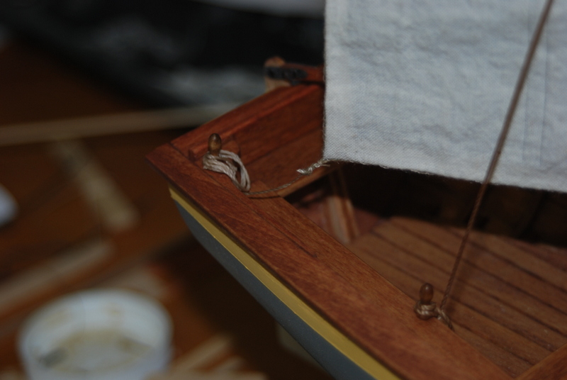
I then sewed the sail to the spar, just wrapping the line around the spar and through the sail. The two loops at the head of the sail are wrapped with this line at the ends of the spar.
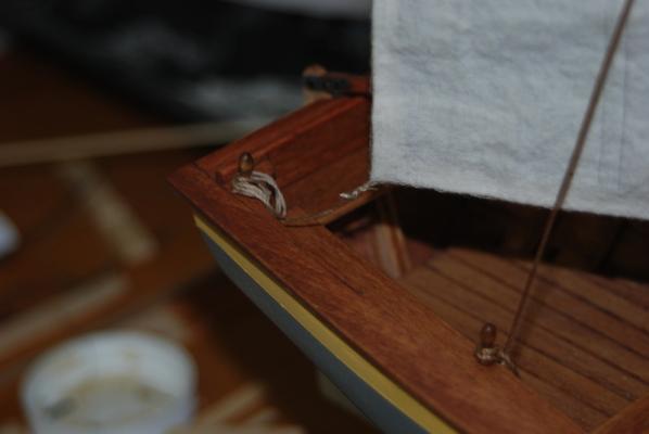
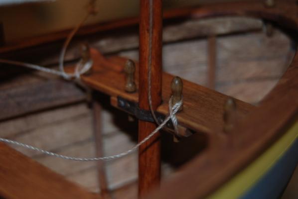
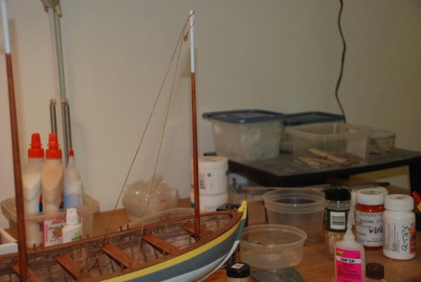
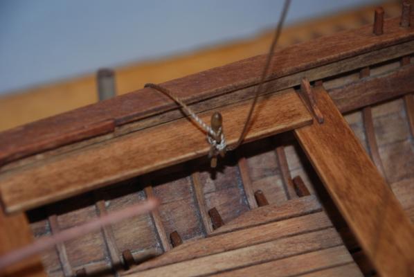
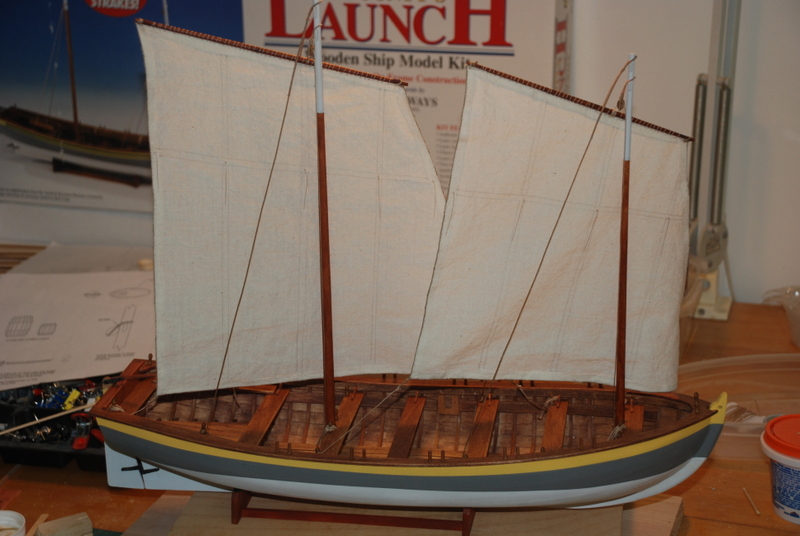
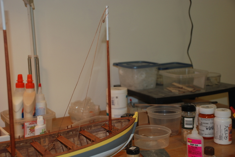
I straightened some of the supplied line for the halyard, sheet and tack. I first ran it through bees wax then over a hot light bulb and through my fingers. This does a nice job for lines that are supplied on cards, which tend to be very kinked. I tied the halyard to the spar with a clove hitch, then ran the other end through the block on the fore mast. I have the spar between the two shrouds. I tied the halyard off to the belaying pin next to the fore mast. I tied the sheet and tack lines to the two loops at the foot of the sail using bowlines, then tied off the other ends to belaying pins. Here is the result:
Now I just have to repeat all that for the main sail, plus I need to add rope coils for the halyards, sheets and tacks.
- captainbob, pete48 and CaptainSteve
-
3
-
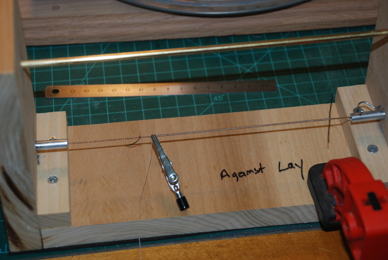
Other than the Pats getting beat by the Dolphins, its been a good weekend. Here are some pictures from last week when I extended the serving on the shrouds. The first one is the served line in the serving machine. I marked the ends of the serving with some thread pulled through the shroud with a needle. I have to remind myself which way the line should go into the machine so I made myself a big note right on it. I also made it so the line to be served is at the bottom of the machine. One advantage I found is then when I put an alligator clip on like in this picture, the clip hits the bottom of the machine so the serving doesn't unwind. I find it also easier to control the serving line since my hand can rest on the table.

The next picture shows my home made serving machine. I didn't have any gears lying around, so I tried rubber bands. While not the prettiest machine on this site, I does work OK. Eventually, I will make a better one with gears, probably before I need it for the Connie build, which will be next.
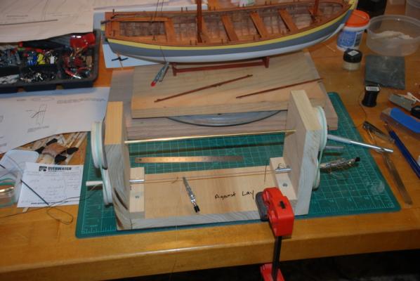
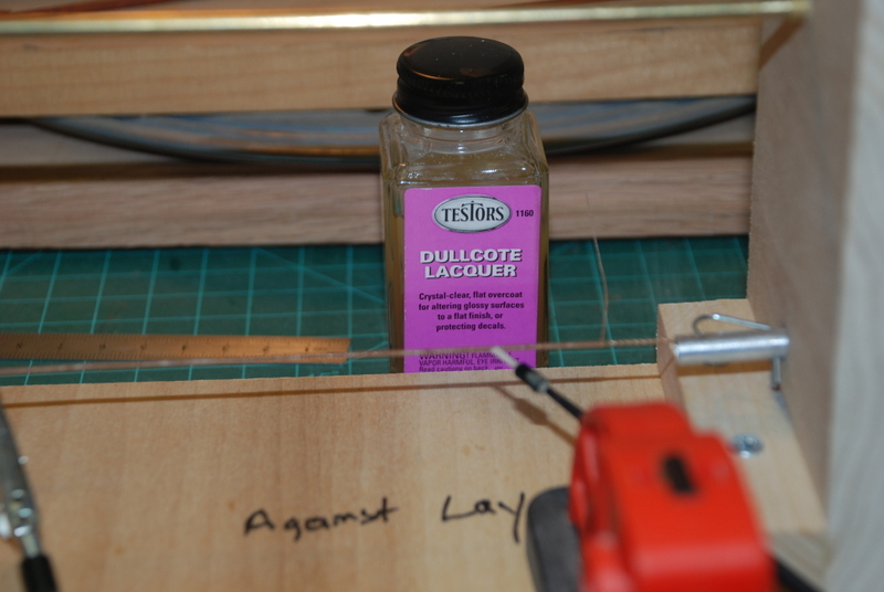
And here is how I finish the servings. I coat them with Dullcote Lacquer and put a tiny drop of CA glue on the end knots.

Here are the results of the new shrouds. I ma much happier with these than the old ones.
-
Great questions, esion. I did not glue the belaying pins into the holes, but that may change. When I was belaying the shrouds, I did notice the pins pulling up a little and the line wanting to go underneath the head, but I was able to push them back down as I belayed the line. If this becomes too much of a problem, I may glue some of them in that I am tying to. The rest I plan to leave loose. If you read some of the other build logs for the launch, you will see that the belaying pins are probably not authentic for this boat, but since I like the look of them I am using them. They used straight metal rods through the thwarts instead of the pins.
As for the sails, I am not putting holes in the corners, but instead seizing loops in the bolt rope at each of the corners. You can see a prototype in the first sail picture above. At least that is my plan. For the reefing lines, I am going to use a needle and thread line through the sail, so no hole there either.
-
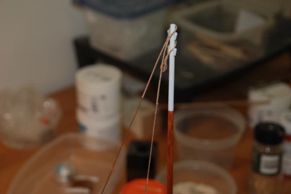
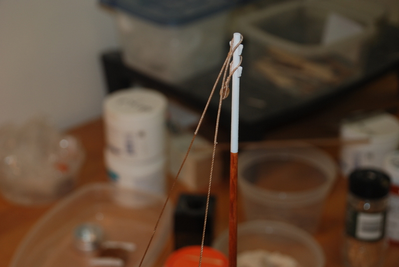
Quiz for today - what's wrong with the picture of the top of the shrouds?
The serving is too short. I figure it should end below where the spars will end up when installed, so I removed the shrouds and I am in the process of re-doing the serving. I am also making the fore shrouds with longer servers.
-
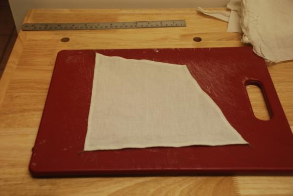
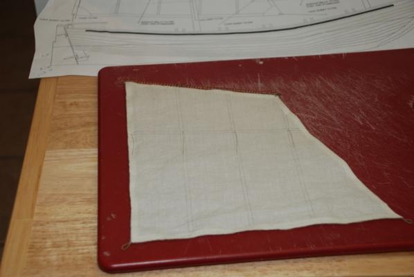
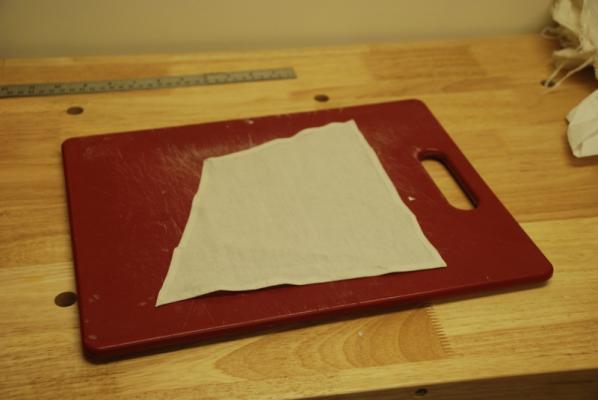
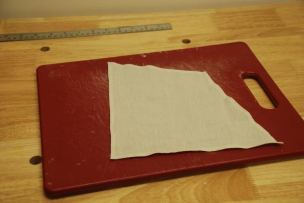
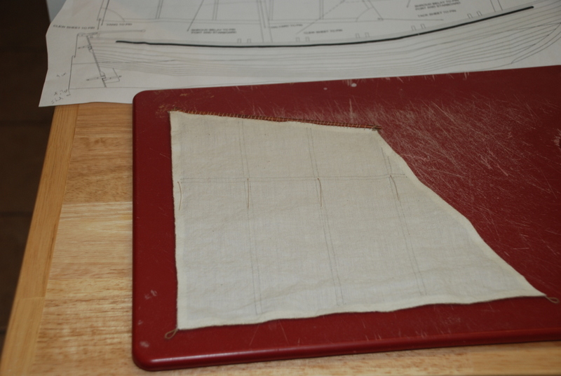
Making sails - This is the first model I will be adding sails to that I have had to make myself. I don't have a working sewing machine and I don't think I would like that look anyway, so I experimented with non-machine sewing techniques. ME supplied enough material so I could make an extra sail, which I did for the experimentation. I bought some Fray Check to seal the edges, so my first thought was to just use it on the edges, cut the sails out on those edges, then add the bolt rope to the raw edges. Actually, my original thought was to make a hem and put the bolt rope in the hem, but it looks like that is not how it was done, the bolt rope should be outside the sail all the way around. So, I cut out the first sail and started sewing a bolt rope to the unhemmed edge. This looked OK in some places but too ragged in others. I then used this same sail to glue a hem over, which looked pretty good, so my approach now is to cut a new sail, glue the hem over, and sew a bolt rope all the way around. I did experiment with seizing the loops in the same piece of line as the rest of the boltrope, which worked great. Here is the experimentation sail:
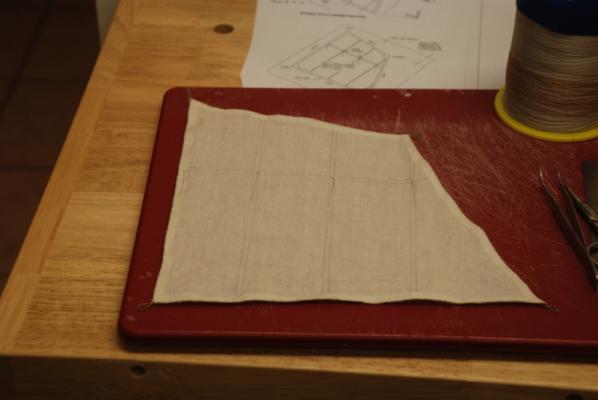
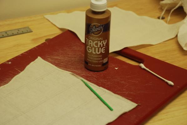
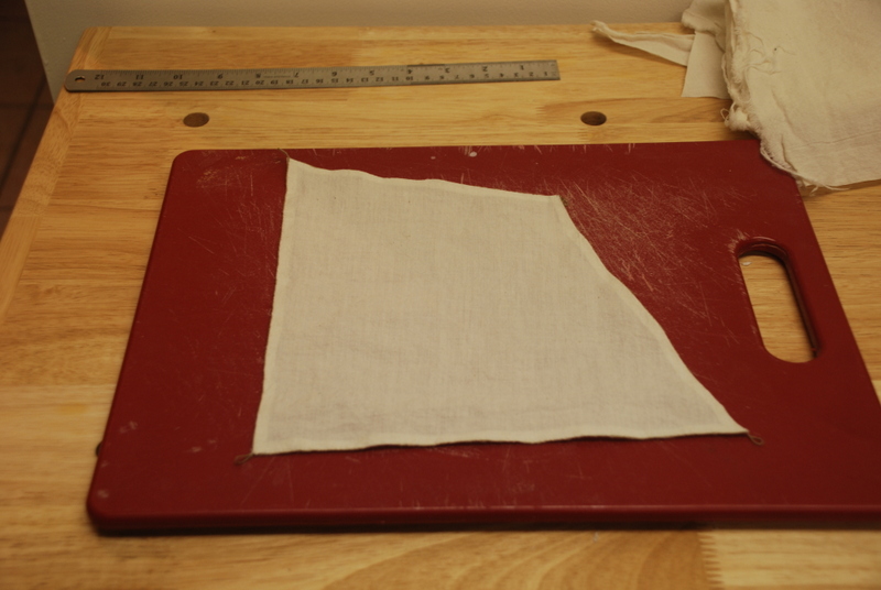
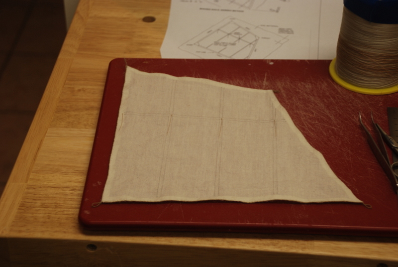
Here is the second sail cut and starting to be glued. I used a Tacky Glue that sticks pretty fast and doesn't run, with a small applicator to apply it. I found on the first sail that if I used my hands to close the hem, the sail could pick up dirt from them, so I used a Q-tip to force the seam together. At the corners, I cut the two hems to meet in the middle of the corner.
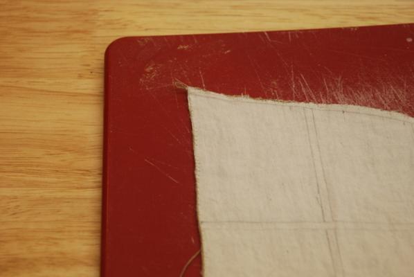
Here is the front and back of the sail after gluing. Besides the bolt rope and the loops, I will pencil in the other seam lines and add reefing lines. The pencil lines on the first sail are too dark, so the new ones will be lighter.
More pictures as the sail comes together. I am going to make one complete sail before starting the other.
-
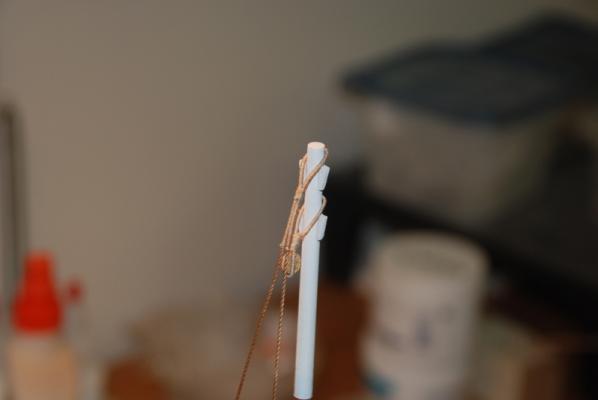
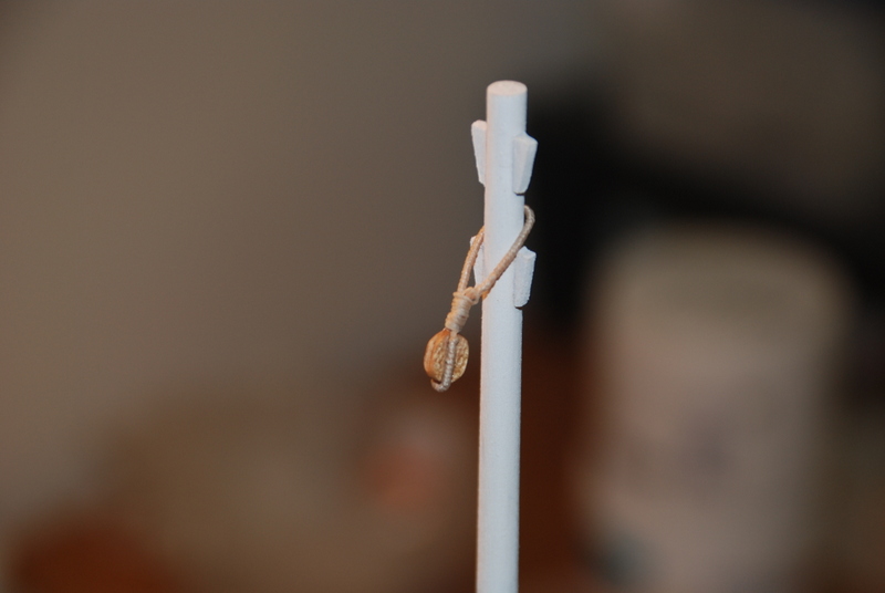
I was travelling all last week, so I didn't get back to building until Sunday. Here are the results of the new served block strops I made. This time, I left the serving a little short so the overlap section was unserved, I used two methods to fix the loop, which both worked well. For one, I used a fake splice, where I just threaded the unserved part on one end through the unserved part on the other end twice, then used some CA to hold the two sides together. On the other, I just tied an overhand knot and fixed it with CA. I then wrapped the loop around the block with the join above the block, which I then covered with a seizing. I used an alligator clip above the join to mark the start of the seizing, then worked my way down to the block. The line is much better centered above the block now.

I also served the middle of the main shroud/stay and seized it around the mast.
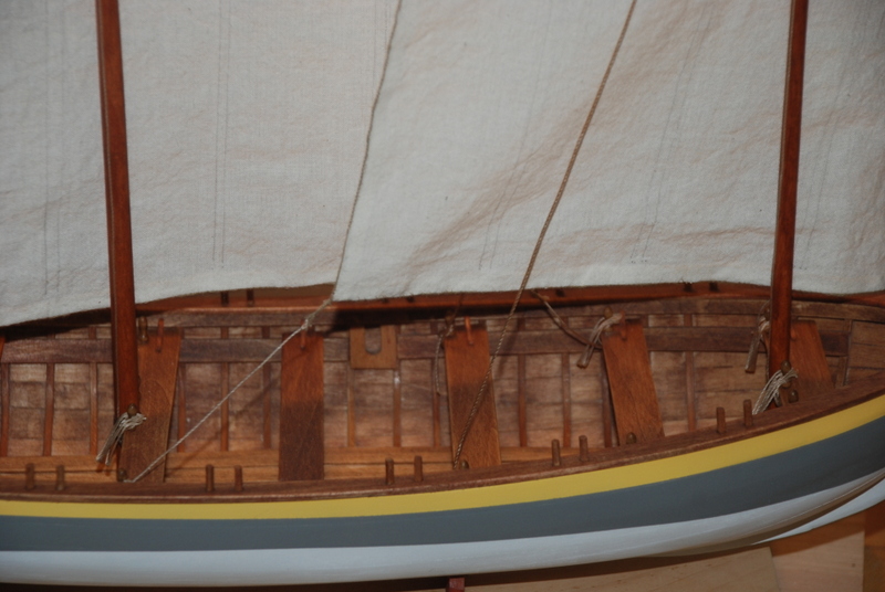
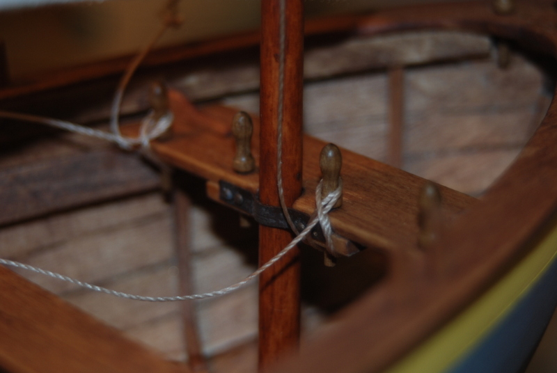
I attached the other ends to two belaying pins in the stern sheets. These are not glued in at all, just fixed by reversing the last loop around the top of the pin.
Another view of the shrouds/stays. You can see the difference with how they are placed from the kit instructions, as shown on the box top. I attached these above the spars instead of below, which matches the contemporary plans.
The next post will talk about the start of the sail making.
- pete48 and CaptainSteve
-
2
-
I think you'll like this build, Keith. Your Bounty build looks really nice. I think you will have no problem with the Launch. I look forward to following your log. be sure to look at the other logs on MSW for this kit. They were a big inspiration for me.
-
Michael,
I just got through reading your whole build log. All I say is Wow! That is some beautiful wood and metal work. You say you were a professional model builder. What a dream job, but I am sure it had its days. I am just glad you still enjoy model building, since myself and probably many others are learning a great deal from your work.
Thank you.


Santisima Trinidad by GTM - OcCre - 1:90 - Kit Bashed
in - Kit build logs for subjects built from 1751 - 1800
Posted
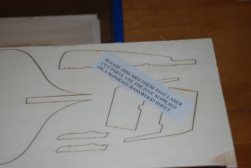
Much nicer than the supplied parts