


usedtosail
-
Posts
2,271 -
Joined
-
Last visited
Content Type
Profiles
Forums
Gallery
Events
Posts posted by usedtosail
-
-
Happy to help. I am certainly using ideas I have seen here too, so that helps a lot. Hopefully this will all work the way I see it in my head.
 Or, it may just turn out to be another "learning experience".
-
Thanks Rich. I have gotten in trouble in the past when not paying attention to these support pieces, so I am being careful now. I will still have problems later, but like you said, that is life and solving problems (up to a point) is actually one of the things that I really like about this hobby. I hope your stern problems get resolved satisfactorily.
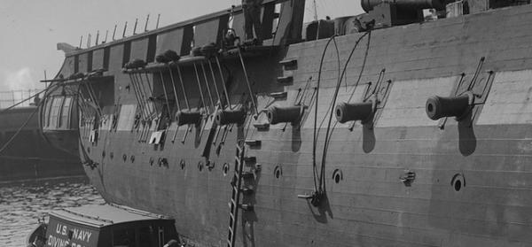
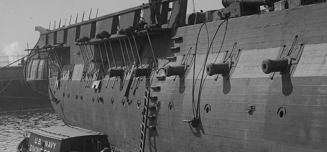
As I mention at the end of my last post, before I can tackle the stern framing I had some design decisions to make. Since I am shooting for an 1812-ish version, the first decision was the height of the bulwarks and taffrail. I had already decided to eliminate the bulwarks in the waist area and replace them with some stanchions and painted cloth panels. For the rest of the bulwarks, I am going to build them only as high as the top of the main rail, so there will be no top gallant rail and the top of the spar deck gun ports will be just under the main rail. I am going by these pictures from before the 1927 restoration. It was after the restoration that a topG rail was added. I am also going to make the top rail out of one wide piece instead of three glued together laterally, and thicker as in these pictures than what is on the plans (3/32" instead of 1/8").
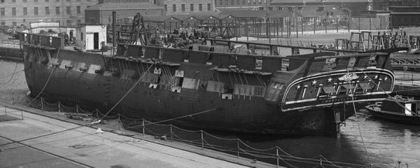
There were some other design decisions that came out of this one, like the placement of the hammock boards and their height and the bow rail details, but I'll show you those as I get to them. The major design piece that I needed for the transom was the height of the main rail where it intersects with the taffrail, so now that I have established that height I can design the transom. I am going with a modified five window design from the Constitution Anatomy of the Ship (AOS) book, which shows a possible transom design in 1812. I scanned this design along with the transom plans from the kit, and using Paint and PowerPoint, I was able to get them to the same scale and start merging the two. The AOS design when scaled to the height of the top rail was too narrow, so I stretched it out to the width of the kit. The AOS design also shows the taffrail above the main rail height, so I moved it down to meet the ends of the main rail. This meant having to move the decorations down to meet the sides of the chase ports, but I think that still looks OK.
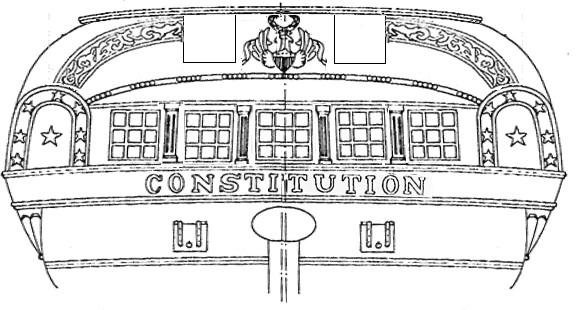
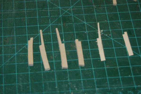
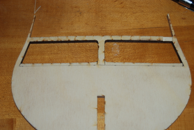
Since I am going with the five window configuration for the stern, and the kit has four inner supports for the transom, I wanted to make sure that none of the windows had supports behind them, since I plan to use acetate in the panes and would like some depth behind them. Since these supports are all the exact same, I figured I could move them laterally a bit without causing problems later, so I came up with a framing plan that has these supports moved and used to frame some of the windows and the two chase ports. I will add other framing as shown in the plan for the other sides, top, and bottom of the windows and chase ports.
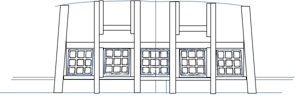
So, working from this plan I am currently adding the side supports for the windows and chase ports to the transom support pieces before I glue them in. This way I can shape them to conform to the shape of the supports before I glue the supports in, which appear to be only edge glued to the transom filler block and last bulkhead. I will probably add some small blocks of wood along the joints to support them better when I glue them in.
-
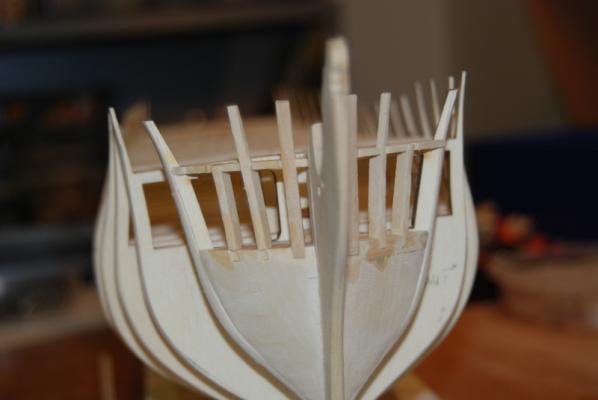
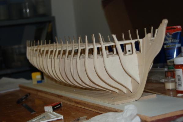
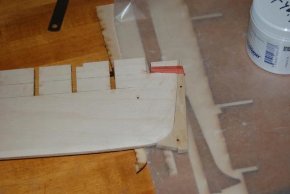
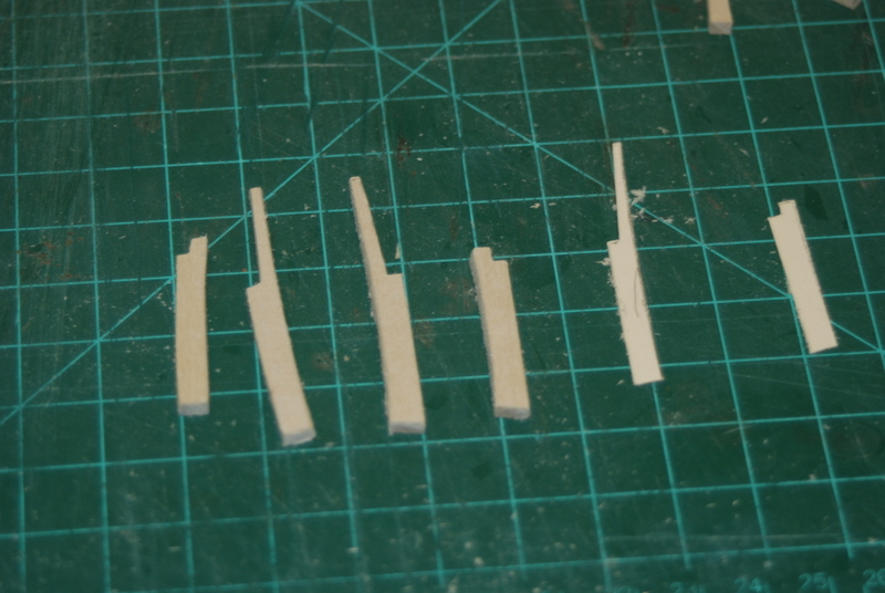
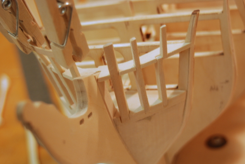
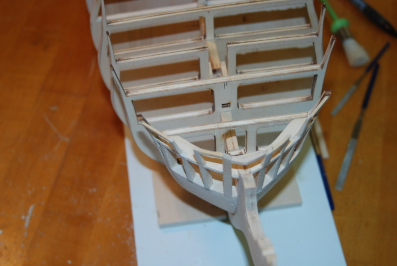
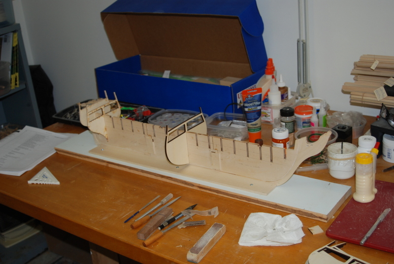
I faired the hull from the keel up to about the wale, then turned the hull over and faired the rest of the way up. I then started framing the bow. I first cut out the main frame pieces, after gluing up three strips of wood for the knightheads. The timberheads I could make out of a single piece of wood. One thing I did was to hold the pieces together to make sure the notches all lined up at the same height then sanded the bottoms flat.
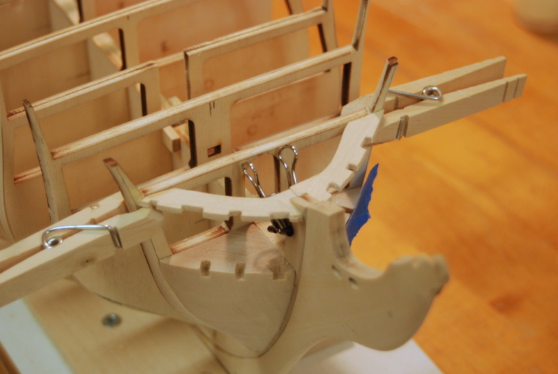
When I was satisfied with these, I fit them into the bow filler block notches and cut out the stiffener pieces that go between them. This took a couple of tries because these pieces as shown on the plans are too short and don't reach all the way to the rabbet. I modified the new pieces to end at the rabbet, then glued them to the stem and the first bulkhead, using clothes pins and a binder clip to hold them at the right height.


I then added the upper piece that forms one side of the head entry. I clipped a batten between the adjacent pieces to get the correct location for the top of this piece.
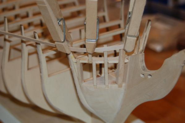
If you look closely at the picture before the last one, you can see that the port knighthead was curved too far back at the top and didn't make a nice curve with the timberheads on this side. Instead of replacing it, I added some wood to the front and removed some from the back to get it into the right shape.
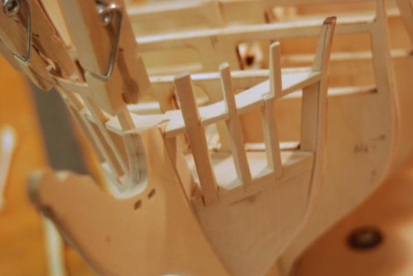
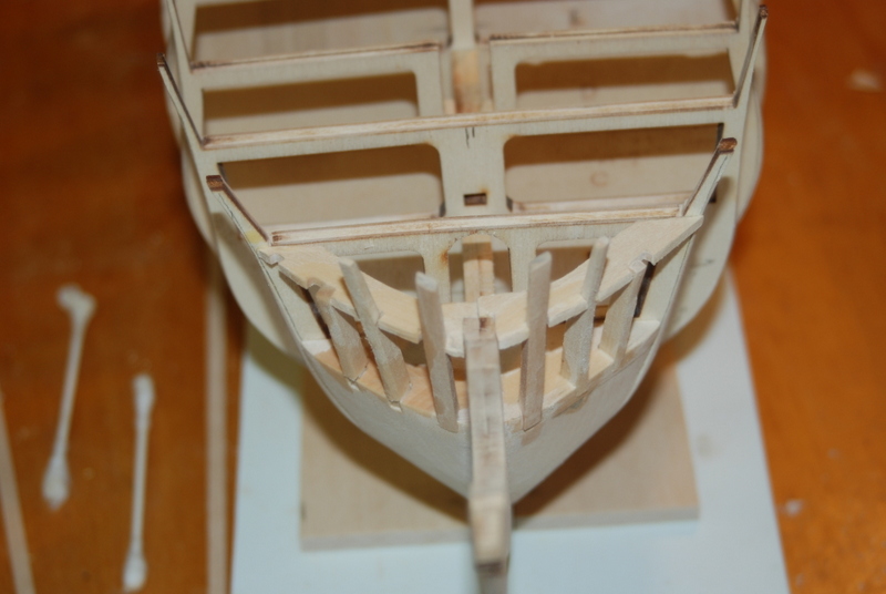
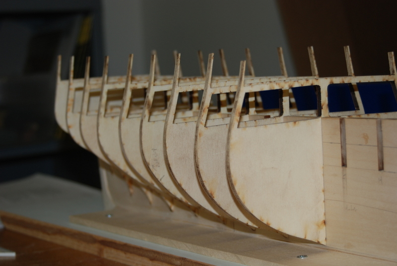
I added the side pieces for the bridle ports and the upper support pieces

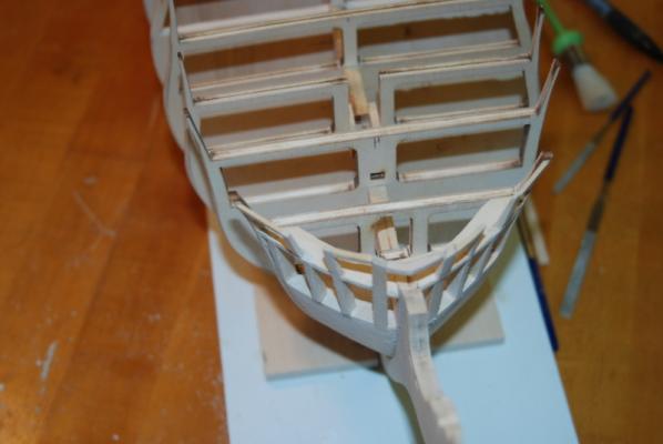
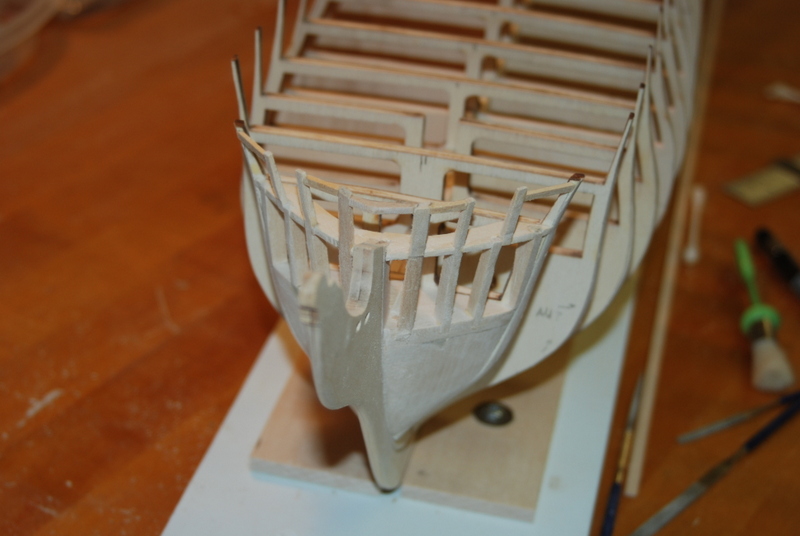
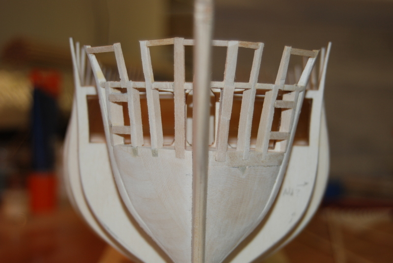
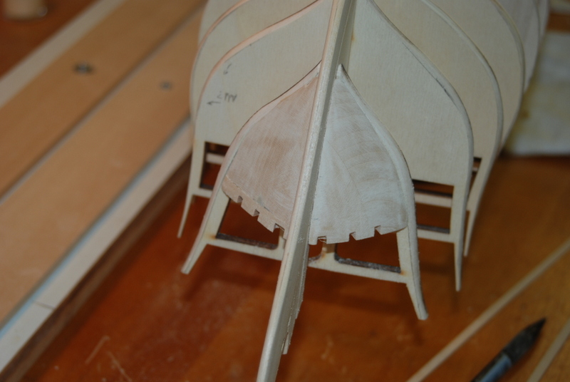
Then the top and bottom of the bridle ports. I faired it all and here is how it came out.

I have some more design work to do before I can tackle the stern framing, but that is next.
- Mirabell61, CaptainSteve, kier and 7 others
-
 10
10
-
I have used copper tape to good results. For preparation, I give the hull a coat of primer and a good final sanding afterwards. I cut a length of tape, then score the individual plates, so that I am applying them one plate at a time. This way I can overlap the ends as well as the sides. The trick is to just score the copper, not cut through the paper, so you can remove each plate with tweezers from the long strip. I have not tried using a ponce wheel to simulate the nails, but I am going to try that on my current build.
-
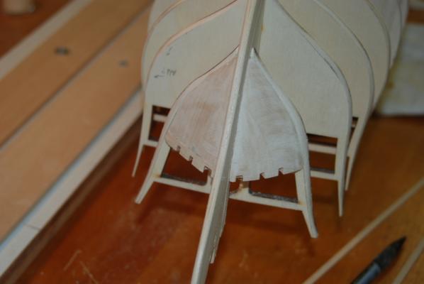
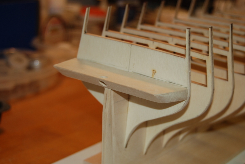
First, an update on the stern filler blocks. I ended up spending over an hour fairing these even more, once I started running a plank strip across them. They have a much nicer flow and a better transition from the rest of the stern bulkheads. The little shelf for the ends of the planks at the transom filler is now even on both sides. These are also now glued into place.
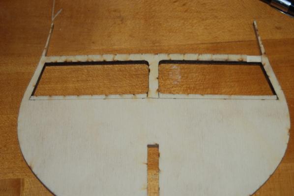
After making the stern filler blocks, it was time to make the bow filler blocks. Piece of cake, I thought. These have a much flatter profile than the stern so there shouldn't be so much sanding. Ha! I had not counted on the little notches, which made this a harder job than I thought.
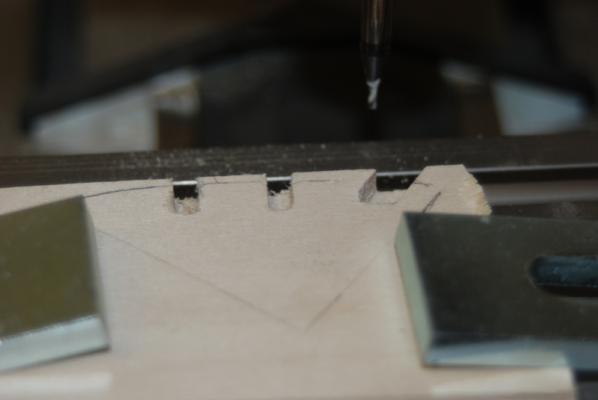
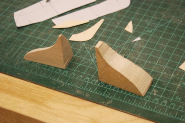
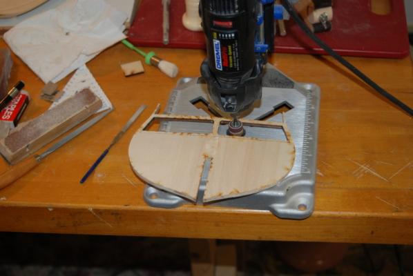
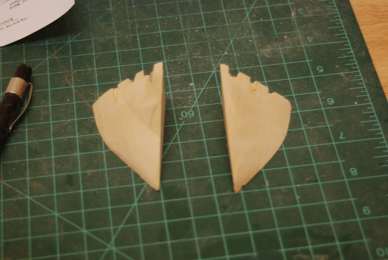
OK, to start, I cut out the blanks for each filler block from the supplied block, cut out the rough shape with the hand saw, and sanded in the final shape using the disk and belt sander, just like the stern blocks. These both came out pretty well, so it was time to carve the slots. I marked them on the top of the blocks using the cut out piece from the plans as a template. I cut a slot on each side using a razor saw and started removing the material in the slots with some small chisels. Well, these came out pretty rough as you can see in these pictures:
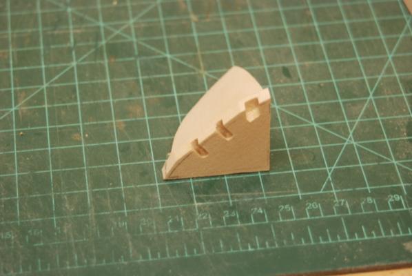
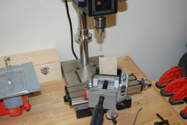
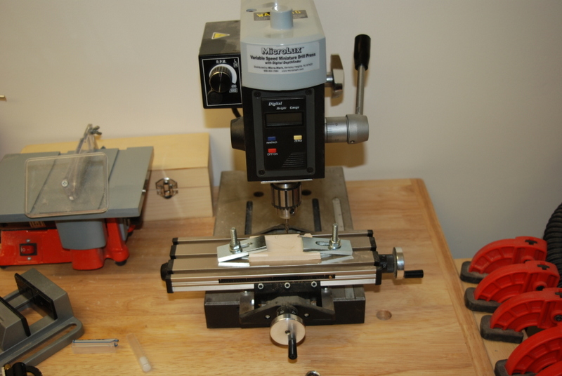
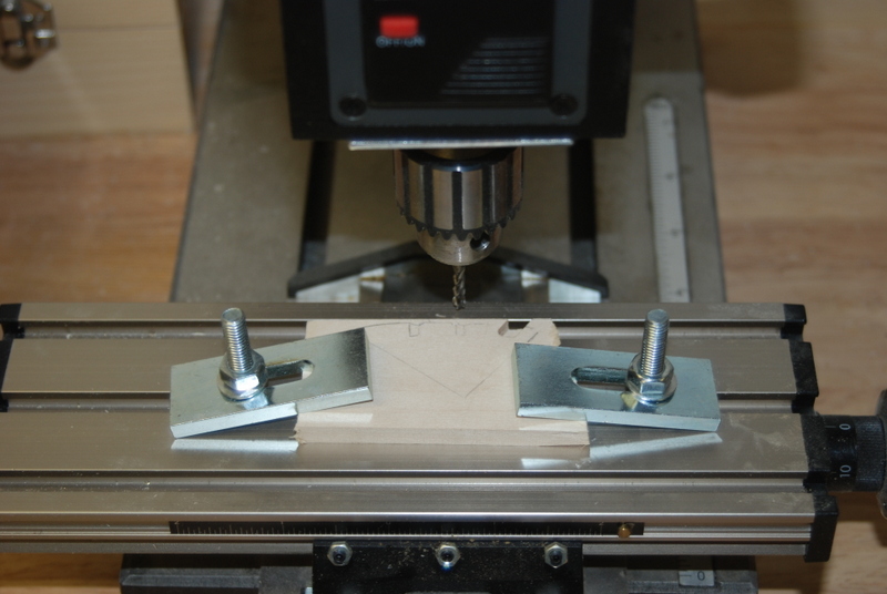
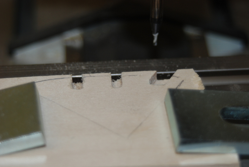
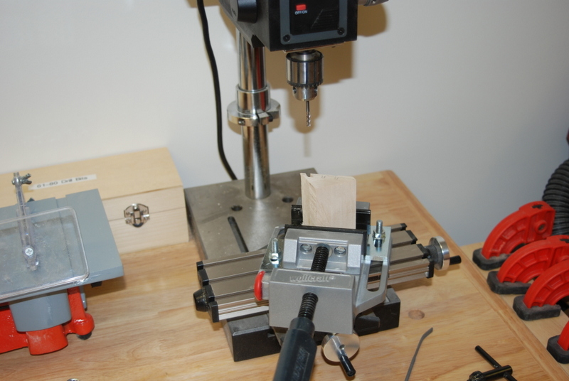
I slept on this but decided the next day that they were not acceptable. I had bought a few end mill bits to use in the drill press, and I figured this was the job for them. I had to figure out how to hold these odd shaped pieces in the vice I had and then it hit me. I could reuse most of the pieces I already had by cutting off the top 1/4" and mill a 1/4" piece of basswood sheet to replace it. The sheet I could hold flat on the XY table that I have under the vice on the drill press. So that is what I did. I used the table saw to cut most of the tops off, then sanding the rest off in the disk sander. I milled two piece of 1/4" sheet, using a 1/8" end mill bit for most of the slot, and a 1 mm end mill bit to clean out the corners.


These came out so much better, I was rather excited. I carefully glued the milled pieces to the rest of the filler blocks, making sure the slots were in the right place in relation to the rest of the filler block.
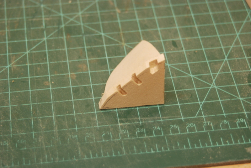
The next day, I sanded one of them down and it fit like it was supposed to.

I started sanding down the second one and managed to round over the top so it was ruined. OK, I thought. If I can do this once I can do it again. So off came the top, another sheet was milled and glued on. When I sanded this one it looked good, but when I fit to the stem, it was too small. Apparently in all the sanding, I was removing little bits of the original section and in the end it came out too small. Another lesson learned.
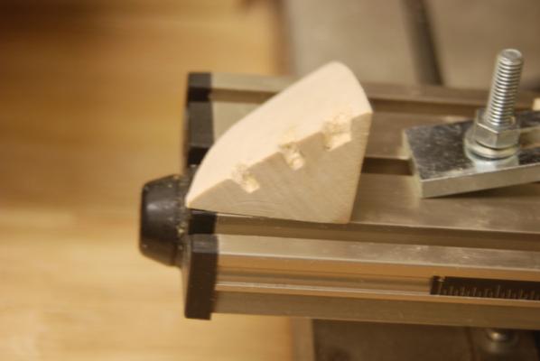
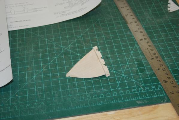
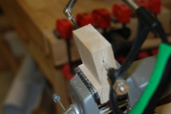
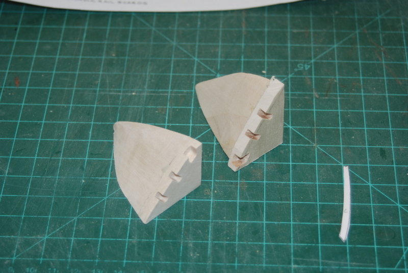
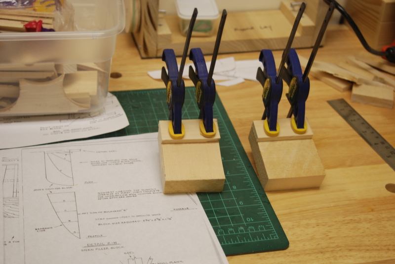
So it was time to start over with the second bow filler block. I had a couple of scrap pieces that I glued together to form a blank. I sanded one end flat for the top and milled the slots first, while I still had a nice rectangular block that I could hold in the vice:
After that, it was just a matter to cut out the rough shape and sand it to the final shape. And here is the result of a week of work:
They are just glued on and there will be some fairing left to do, but I am relieved that they are finished.
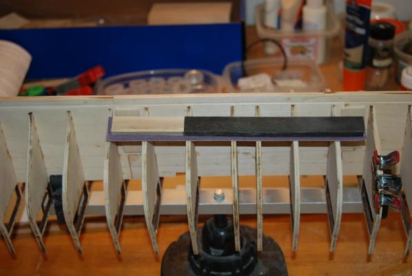
While the glue was drying on various pieces this week, I also did some fairing of the bulkheads. I glued some sand paper to this sanding stick and used it to fair down the bulkheads. As I noted in a previous post, some of the bulkheads were not wide enough in some places, so in these areas I glued some thin basswood strips to build them up, then sand down to meet their neighbors.
After the bow filler blocks dry, I will do more fairing then start the bow and stern framing.
Thanks for watching.
-
Me too. I am looking forward to seeing how you put your own spin on this model.
-
I know that only because the good Cap'n has been very interested in my build log. I have a feeling his will come out much better than mine.
- CaptainSteve and GLakie
-
2
-
The Bounty Launch, me thinks.
- GLakie and CaptainSteve
-
2
-
Oooh OOh I think I know.
- CaptainSteve and GLakie
-
2
-
Bob, I am glad I found your log. The schooner looks really nice so far. I am looking forward to following along.
-
-
Stern filler blocks:
The first one of these took me much longer than I thought it would, but the second one was a lot faster. Isn't that how it always goes.
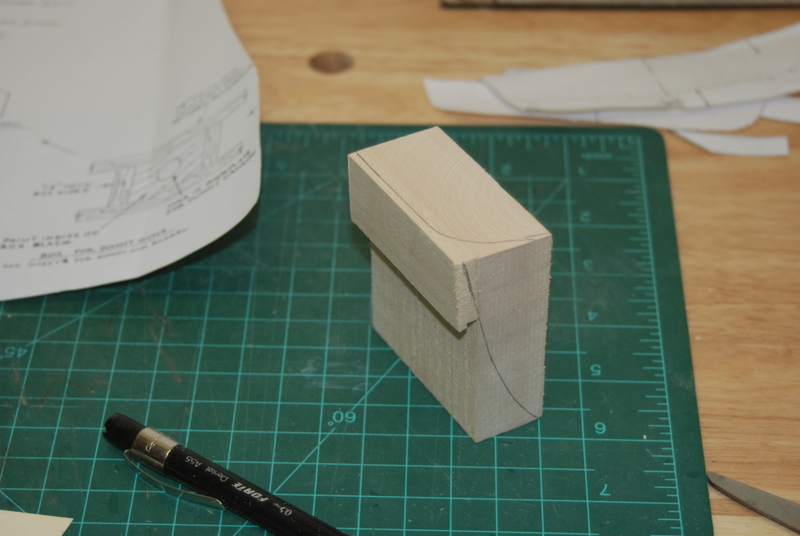
I first glued up two blanks to use for these. Instead of the 2" wide block that came with the kit, I used a a 1" piece of basswood that I had and glued on a 1/4" piece at the top, just to reduce the amount of waste.

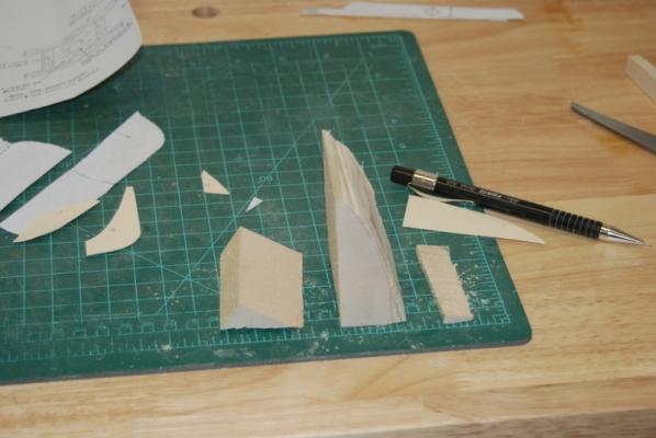
I then made templates form the plans and traced the edges onto the different sides of the blank.

I cut the side profile with a coping saw, then taped the pieces back together and cut the S shaped back profile on the scroll saw. This took a while since my little scroll saw and thin blades didn't want to follow the lines nicely. But, I eventually got it cut out.
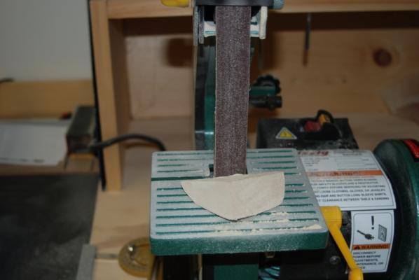
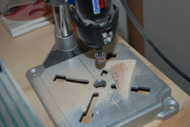
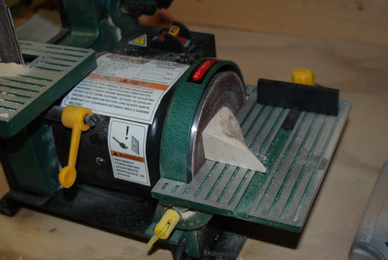
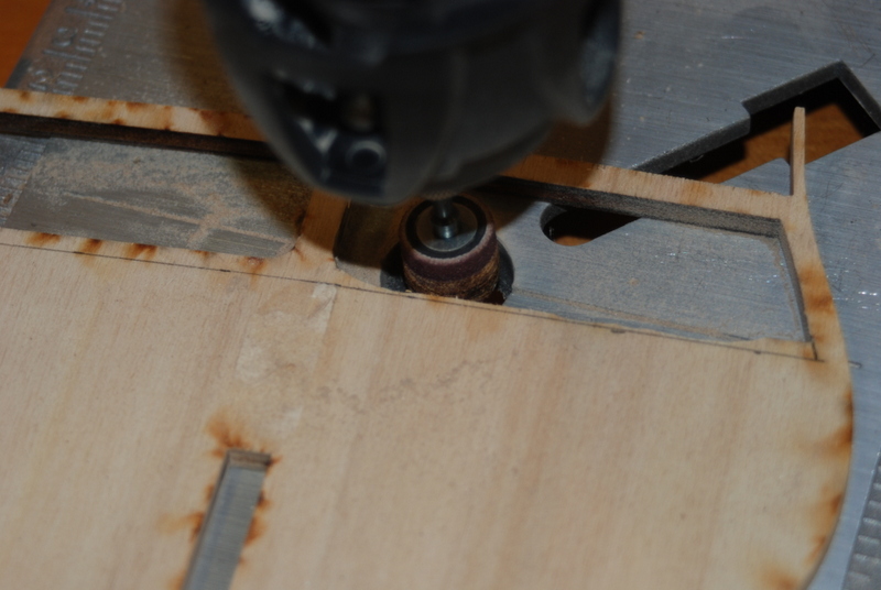
I then used the belt and disk sander to square up the top and side edges so they fit flush to the last bulkhead and the keel. I used them to remove a lot of the material in the middle of the blank, and I also used my Dremel tool in the workstation with a sanding drum to get into the tighter curves. I finished up with a rounded file and some sanding blocks, and used the profile templates I made form the plans to check the overall shape of the block. I got the overall shape but the top edges were too small compared to the transom filler. Instead of remaking a whole new piece, I cut about 1/2" off the top of the blank and glued on two 1/4" pieces that were wider. After they dried, I sanded them to fit the existing shape of the blank but left the tops a bit wider than the template.
It was at this point that I realized that I had left the underside of the transom filler piece too long, since the stern filler piece did not fit all the way to the back edge. I flipped the hull over and held it in a keel klamper, then used a sanding block to sand the back edge of the transom filler back to the correct length. I left about a 1/16” flat area so the planking can end nicely into the transom filler. I found it much easier fitting these filler pieces with the hull upside down. I then used the disk and belt sander to sand down the added top pieces to match the templates and flow into the original filler piece. I had to remove material in the middle of the filler to match the profile templates. For this I used the sanding disk in the Dremel tool in the workstation. I left the drum above the base so I could get the piece under the disk if I needed to.


I ended up with a nice general fit, but then I worked the edges some more with sanding blocks and the rounded file to get the edges to flow into the bulkhead R and the rabbet along the stern post. I ended up increasing the rabbet depth some with an X-Acto chisel so a 1/16” plank would fit nicely into the rabbet. When I had a good fit, I gave the whole piece a final sanding with medium and fine sandpaper. I was very happy with the way this filler piece turned out, but it took about 6 hours for make it.
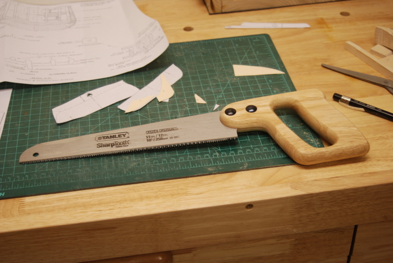
The second one was a lot easier. I bought a few tools to make this process a little easier for this and the remaining filler pieces, which included heavier scroll saw blades with larger teeth and a small hand saw. I found this saw at Home Depot and it worked really well:

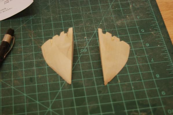
I used the hand saw to start the cut of the excess off the side profile, then the coping saw to finish it. I drew the side profile on both sides of the blank this time so I could check that I was not cutting off too much on either side. I taped the cut off pieces back on and cut the back S profile with the scroll saw with the new blades, which worked much better, especially after I increased the speed of the saw.
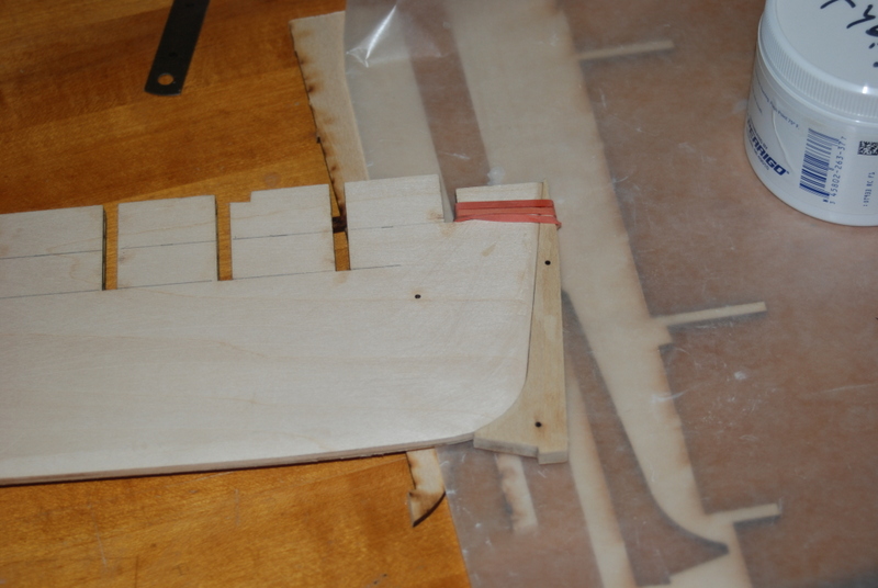
I then sanded the edges to the template lines. I again removed the center material with the Dremel sanding drum set up, and finished off with the sanding blocks and file. The rabbet on the starboard side was in good shape so I did not need to so anything with it. This side only took me 1.5 hours, and the two piece seem to match very well. I'll give them a final sanding along the edges when I fair the hull. You can see that the tips got pretty thin and ended up breaking off, but there is plenty of support from the bulkhead at those points, so I didn't bother to replace the tips. The pieces are not glued in yet, but will be soon.
 Lots of saw dust created to make these two fillers, but it was pretty fun overall.
 -
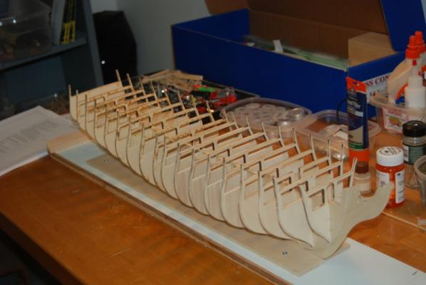
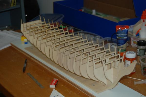
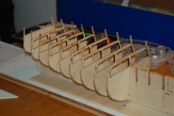
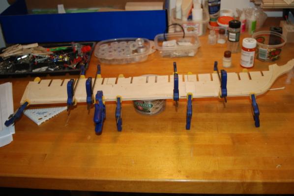
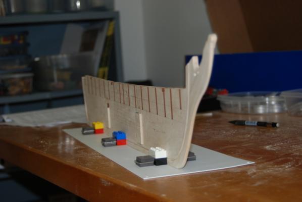
Adding the bulkheads:
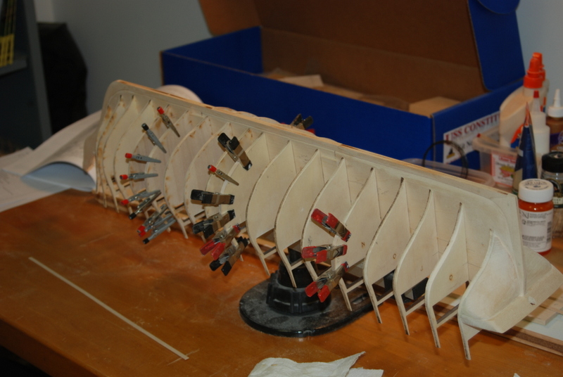
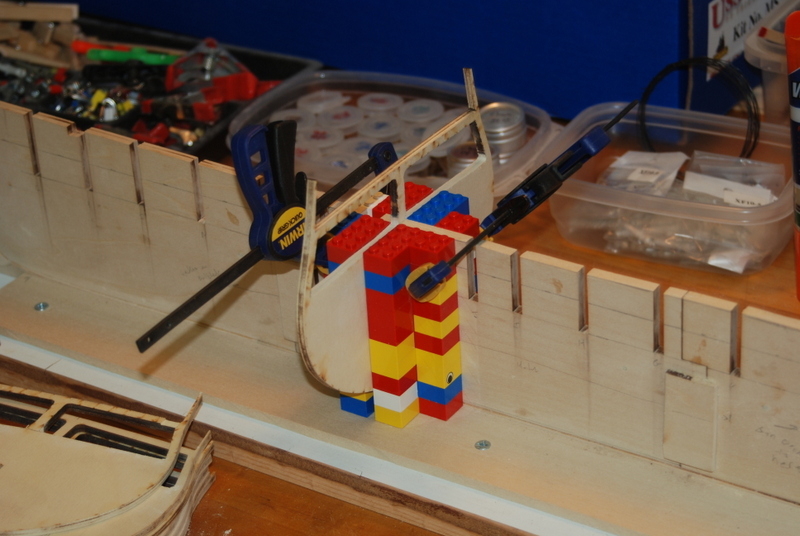
This was pretty straight forward. I had made these Lego corners for a previous build, but they were about half as tall as I needed for this one. A quick trip to the attic to find more of my son's Legos and I had what I needed.


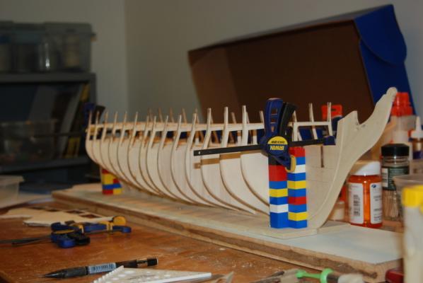
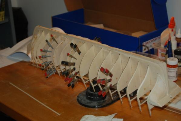
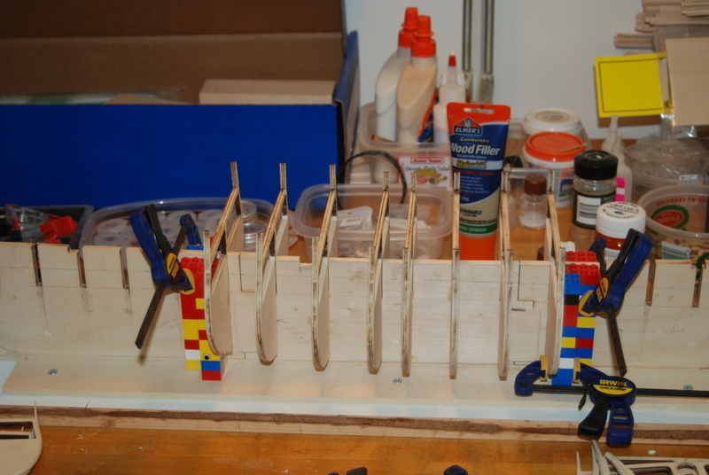
And here they are all attached. Overall, this process took a few days as I was only adding them two at a time and letting them dry a few hours before the next two. The deck beams seem to have a nice run to them without any high or low spots. I know the sides of the bulkheads still need some fairing, which I will get to soon.
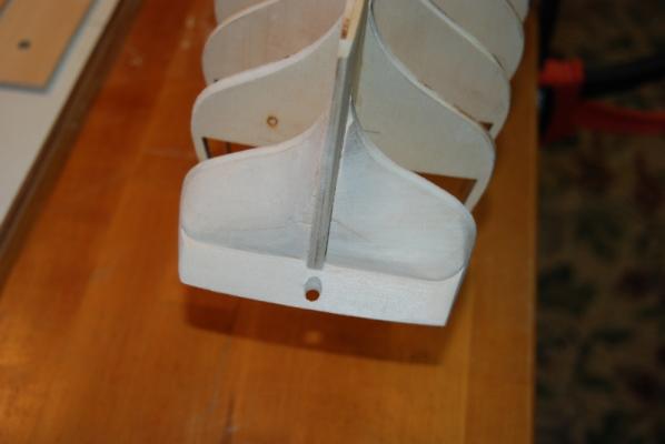
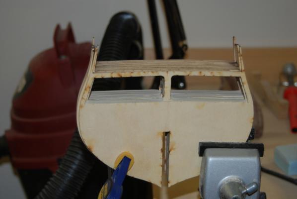
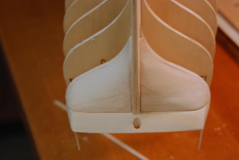
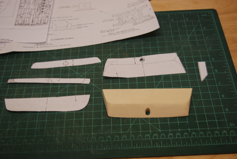
While this was going on, I started making the transom filler block. I used the supplied basswood block and cut out the templates from a copy of the plans, which I glued onto the top and bottom. I then used a disk sander to thin the block down and rough in the shape, then a variety of sanding blocks to get it close to the final shape.

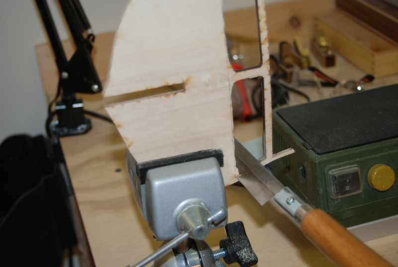
I drilled the rudder hole, which is at a slight angle, by holding the filler piece in an adjustable vise and setting the angle to match the stern post angle, then hand drilling a series of small to large holes, finishing the hole with a couple of rat tail files. I used the raw kit supplied rudder to test the fit, so I left it a little tight, since the rudder stock will be sanded round later.
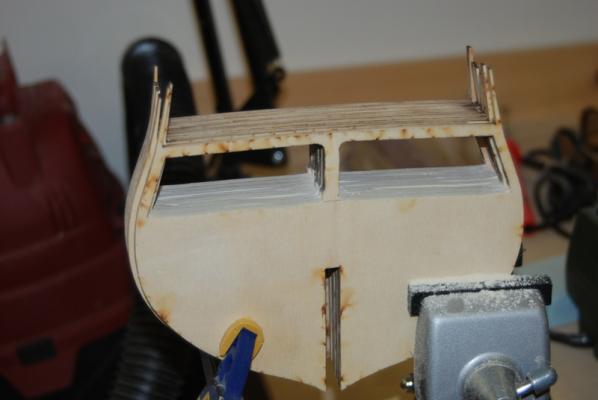
I test fit the transom filler piece to the stern, using the center line on the plans to line up with the center line of the last bulkhead. Getting the piece to be aligned horizontally was a bit of a challenge, but I used the transom pieces as guides, so that when they were level all the way across that was the right angle for the filler. I had to reduce the thickness of the filler a bit more and may still take some off before adding the transom pieces. I glued it on with white glue but did not find a good way to clamp it, so I held it in place until the glue was tacky.

I am working on the two filler pieces that sit under this piece and will have pictures when I finish them.
-
Wow. I love all that metal work. It looks fantastic.
-
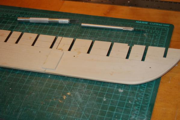
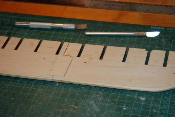
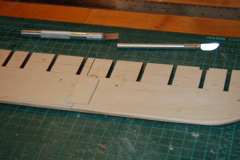
To continue on dealing with the gun deck, I set up my Dremel tool in the Workstation with a sanding drum to sand down the area on the bulkheads to be removed. This set up let me quickly switch bulkhead sides and change bulkheads by raising the Dremel tool. There is a hole in the base of the workstation that allows the drum to fit into, so I could get the whole width of the bulkhead in one shot.

The drum doesn't fit in the corners, so after doing what I could with the Dremel, I put the bulkheads in a vise and used a razor saw to cut out the material in the corners.

I then used a flat file to clean up the cuts.

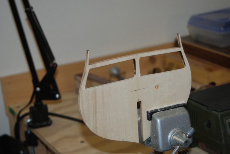
When I had all of the bulkheads cut, I stacked them together and aligned the top rails, then used a flat file to get the cuts even. Here is the before picture:
And here is the after. I think I could do more clean up but I don't want to remove too much, so I am going to wait until the final sanding after removing the center posts for any additional material removal.
Finally, to remove the material on the hull former, I just used a razor saw to cut close to the lines, then a sanding block to finish off the cuts so they were all straight. I had to deepen the notch for the main mast, which I did with some careful chiselling. Well, not really so careful, but the pieces broke off cleanly and I was able to cut the notch out with a razor saw at that point and glue the two side pieces back in. For plywood, this stuff splits pretty easily.

The next task will be to carefully glue the bulkheads to the hull former.
- CaptainSteve, CaptMorgan, mspringer and 4 others
-
7
-
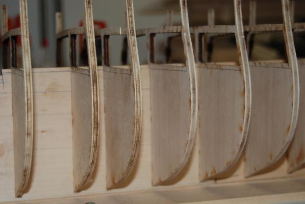
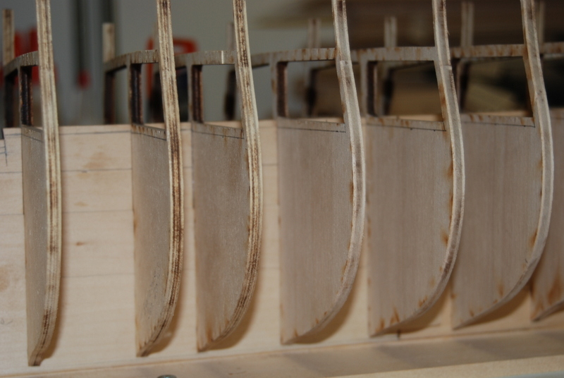
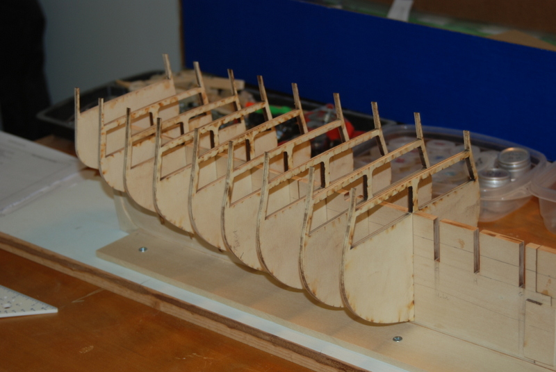
I finished cleaning up all of the bulkheads and here is how they look (unglued) in the hull former:
As I mentioned earlier, I am going to attempt an 1812-ish version for this model, since taking a hard model and making it harder just seems like the right thing to do
 . So I want to have the main hatch open with beams across, instead of the closed hatches that are on the ship now. This one decision led to many others. Since the hatch will be open, the gun deck will need to be added since it should be visible when looking into the hatch, even though there will be a boat or two on the beams. And if the gun deck is seen, it has to have real cannons (not the dummy barrels), which should be fully rigged. So that means I need to buy the cannon set from Model Expo since I need about 12 cannons in the area that can be seen from the hatch. Other things could be seen too, like the chain pumps and hatches leading down to the berth deck, so these will be added too. Diagonal knees - sure. Deck planking and treenails - sure. Rivets on the walls - probably not (I have to draw the line somewhere).
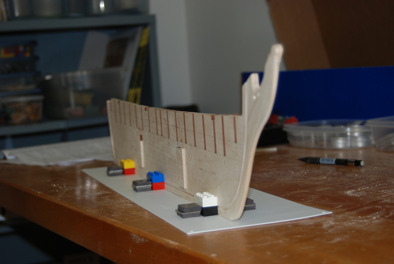
I am going to use 1/16" thick planks for the gun deck planking, but I also want to put them on a basswood sheet backing, which will be another 1/16". Since the bulkheads are cut at the top of the gun deck, I need to remove 1/8" from those that will be seen from the main hatch, which are E through L. I measured down 1/8" from the cut out and marked the line to be cut to. I am going to leave the center supports and spar deck beams in place for now until I add the spar deck waterway. I will cut these out in place and clean up the center of the bulkheads so there is a smooth run of the gun deck across them, before installing the gun deck.
Since the top of the hull former is at the same level in this area, I also need to cut it down by 1/8", so I marked it too:
In the next post, I will show how I cut these areas out.
-
You can still get 70mm film rolls on eBay, but you would have to strip the emulsion off. Photographic fixer will do that
-
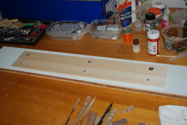
I decided to build a new building board that would hold the keel more rigidly and straight. I cut a 1/4" by 24" by 6" basswood board in half and screwed one piece to a larger board. I then put three slots in the other board and screwed it down on the larger board. The slots let me adjust the width of the keel slot and to tighten it to the keel.

I have been cleaning up the bulkheads and adding the bevels to them. I have about half of them done so far. It takes about 15 minutes to do each one so it is taking so time. So far, the fairing looks pretty good, although I have not adjusted them for squareness to the keel yet. They are just slid into the keel for now and not glued in yet.

- ScottRC, CaptainSteve, SkerryAmp and 1 other
-
4
-
-
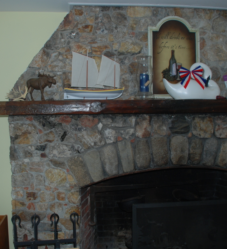
One last entry just to show the model in its new home, on the mantle in our lake condo in New Hampshire:
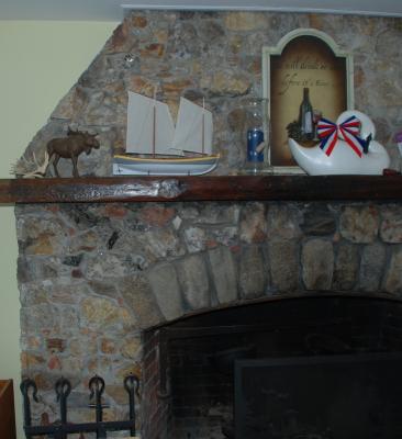
My kids provide me with the moose themed items on Father's Day. I am running out of places to put them.
- captainbob and CaptainSteve
-
2
-
Thanks Steve Bob and Jay. I am with you all as I have already had the plans copied at Staples. This lets me cut out sections and use them as templates. One\ the bulkhead plans, there are two lines on one side, one for the fairing line and one for the edge of the bulkhead. The asymmetry I am seeing is in the bulkhead edges on each side. I found another one last night that was off, too. Thanks for the heads up on the copper tape. I have an extra roll that I bought a few years ago, but I will have to see how they match up in patina.
-
More progress on the keel. Here is the stern post being glued to the former. I used a rubber band to hold it while drying, after making sure it was centered.
I then sanded and fit the three bottom keel pieces between the stem and the stern post. Lots of clamps to hold them together while the glue dried.
Then I filled the holes in the keel pieces that are there to help align the two halves when gluing them together, and also used a little filler on the joints. I sanded the joints flat, then drew lines on the stem and stern post for the extent of the tapering. I used a #22 X-Acto blade and a sanding block to add the tapers. I think they came out pretty well. I was a little concerned because I messed this step up on the Bounty Launch and was never happy with the way the stem looked.
I have started checking the bulkheads for symmetry. I found one that is a bit small compared to the plans, but the plans are also not symmetrical. I am going to add some strips of wood to the edge of that bulkhead and sand it down during the fairing process. The other bulkheads that I have checked look pretty good. I have four more to go. I am also adding the reference lines and tapering lines as I go.
-
I am very sorry to hear this Mick. Hopefully you can get some building in to take your mind off other things.
-
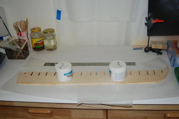
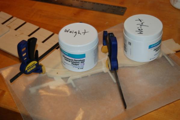
Work on the keel continues. I glued the three pieces of the keel former together using epoxy, with some weights to hold them flat. Those jars contain rolled up pieces of lead sheeting.
I then carved the rabbet into the bottom edge. I used a #22 X-Acto blade and an X-Acto chisel blade. I cleaned up the rabbet after carving with a small sanding block.
I enlarged the holes in the stem to slots for the rope gammoning by drilling holes in the other end of the slot and cleaning them out with small files. They came out a little wider than I wanted, but should be OK once they are trimmed by the cheeks or head rail (whatever that piece is that follows the curve of the stem under the bow sprit) and have rope in them. I sanded the inside edge of the stem to fit on the keel former without gaps, then glued it in place with white glue. I used some clamps to hold them together and some weights to keep everything flat. There is some scrap wood under both piece to keep them level, too.
In the mean time, I am still going through all the Constitution build logs and other materials, making lots of notes. I still have many decisions to make going forward, but I am starting to get a pretty good idea of where I want this build to take me. There is so much information here that is really making this job so much easier than it could be, and so many good ideas and ways to tackle the different parts of the build. Again, I thank all those who have come before me on this path.


USS Constitution by usedtosail - FINISHED - Model Shipways - scale 1/76
in - Kit build logs for subjects built from 1751 - 1800
Posted
Thanks dragzz.
Russ, thanks for the tip. I have been looking at both the Hull model and the Corne painting of the period for a while too.
There are some major differences, like the number of windows, and as others have discussed in their build logs there is really no good source. As you suggest the Hull model may be the best reference since is was made by the crew, but I am not crazy about that stern configuration. The Corne painting is better and does have some of the elements I like, but may have some inaccuracies because it was painted at a later time. That is one of the reasons i am calling this an 1812-ish build.