


popeye2sea
-
Posts
1,933 -
Joined
-
Last visited
Content Type
Profiles
Forums
Gallery
Events
Posts posted by popeye2sea
-
-
The photo shows the topmasts and topgallant masts "housed". All of the upper yards are "struck" or sent down. The topsail yards are lowered to the caps. The lower yards are also lowered to reduce weight aloft. The ship is under "bare poles," (no sails) and "scudding" (drifting) before the wind.
The ship would be forced into this condition under a heavy gale with high winds and high seas. She may have a sea anchor set out to keep her from getting beam to the waves so she doesn't capsize.
Regards,
Henry
- davyboy, Keith Black, allanyed and 3 others
-
 6
6
-
Bill,
1114 is the mizzen sheet and you are correct it would not be fastened to the flag staff. It would have an eyebolt in the deck for the lower block and a cleat for belaying. But, if you find moving it would be a hassle, leave it there. It is the least offensive of the three that Heller wants to belay on the flag staff.
Regards,
Henry
-
Hellerism. Omit.
BTW, Line 1040, the main brace, should not go to the flag staff, either.
Regards,
Henry
-
-
She looks great, Bill. The only suggestion I would make is to try and get the kinks out of the slacked lines. Perhaps they can be 'painted' with dilute white glue and then held in place until set?
I am not sure which method works best for this, but I am sure it has been done here on MSW.
Regards,
Henry
-
Stiffen a good length of thread with CA adhesive. It will turn it as hard as a needle.
Regards,
Henry
-
I think we mentioned previously that the hauling end of the line leads inboard along underneath the yard. As far as the tackle fall itself is concerned, the reef tackle is only in use to pull the reef band up to the yard for reefing (shortening sail). When the sail is furled the lower block of the reef tackle fall is un-hooked from the reef band cringle and is brought in under the yard and lashed to it. There is sometimes fitted a tricing line on the lower block to help facilitate hauling it up to the yard.
Regards,
Henry
-
2 hours ago, Bill97 said:
Also, the bow lines would be slacked and as their cringles reached the yard they would have been loosed or un-toggled from the sail.
Also Henry would you care to elaborate a bit more on the bowlines connected to your he course sails that have folded back. Should I just remove them or have them drape loosely toward their belay point?
The bowlines are normally toggled or knotted into their cringles (loops turned in on the bolt rope on the sides of the sail). Oddly enough, the knot employed is the bowline knot.
When the sail is close hauled (yard set at an extreme angle to the mast) the bowline on the weather side (up-wind) is hauled taut and serves to keep the proper shape to the belly of the sail. The leeward bowline (down-wind) has no function and so remains slack.
When the sail is gathered up to be furled, the bowlines are removed. I am not 100% certain if the normal practice was to seize the now removed bowlines and their crowfeet (sp?) to the approximate location on the yard where they would be when the sail is hauled up. It seems to be the practice with modelers to depict them this way when sails are either furled or not fitted. Seizing them on the yard in this manner makes sense due to them being in an accessible position when the sail is set the next time.
In your case, with the sails only raised slightly, the bowlines would probably not be removed because the sail is likely to be sheeted home (fully set) again in the near future. The bowlines would simply be slacked.
Regards,
Henry
-
5 hours ago, Bill97 said:
Yes Henry. That is my line number as well. I will see if I understand what you say to do. When you say “they cross over to the opposite side through a hole in a the stem” am I correct to to understand they go forward to a hole in the knee where Heller shows, then they both pass through the same hole to the opposite side and then up to the beakhead??
That is the idea. Although, in my opinion there would be two holes or a separate fairlead with two holes fitted on the front of the knee. But, the one hole will suffice.
Regards,
Henry
-
There are two tack lines. One for each corner of the sail. They both lead forward and cross over to the opposite side through a hole in the stem. Then they lead back up to the beakhead bulkhead where they belay on the rail. Or you can take them to one of the forward pins on the bulwarks. In my rigging plan they are lines 1123. Don't go by the Heller plan. It is wrong
Regards,
Henry
-
On the question of one rope or two. I have no definitive answer. If it helps with the justification, there is a tackle for each rope up in the overhead beams of the inside deck. As you said 300 lbs. is a lot to haul with a single rope.
Regards,
Henry
-
9 hours ago, Veszett Roka said:
Bill,
i think Henry thought these reef lines on the foremast. I believe it is easy to comb them down if you pinch the sail forward a bit, then the sail's curve will push the reef lines down:
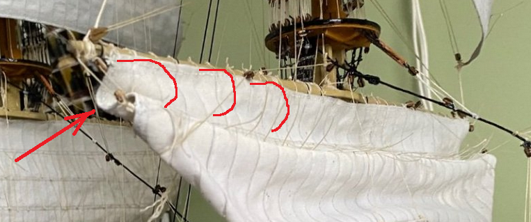
I draw the three red curves just for illustrate what i thinking. The red arrow points to the backward curve of the sail whic (in my theory) need to push towards the bow to form the red curve lines.
No, Bill got my "point". Pun intended. I was 'reefering' to the line of reef points sticking out from the reef band due to the bulge of the sail cloth.
Regards,
Henry
-
-
Bill, at the risk of causing you a bit more grief with one last suggestion for those sails.
You should knock those reef points down so that they don't look like stray whiskers or eyelashes.
I think the sails look great.
Regards,
Henry
-
That will look good too! It adds some interest to the rig.
-
You have it right Bill. The clew lines pull the corners of the sail up aft or under the yard. This is done first. Then the bunt lines and leech lines haul all of the loose slab of sail cloth up towards the front of the yard. When the sails are to be furled the crew lays out on the yard, reaches down in front of the yard, and starts to grab the loose canvas and hauls it up in accordion pleats on the top of the yard. When the final bundle of sail is hauled up to the yard the previous folds are stuffed inside the "skin" of the final fold. The clews of the sail will then be remaining as small triangles of canvas hanging below the sail bundle.
Also, the bow lines would be slacked and as their cringles reached the yard they would have been loosed or un-toggled from the sail.
Your mainsail looks like a pretty good representation of a sail "hanging in it's gear." The fore sail starboard bunt line may need a little adjusting to make the foot of the sail appear to hang more fair.
Regards,
Henry
P.S. I responded before seeing your last photo. Obviously, the photo I am referring to is the ones with the sail clewed up.
-
The mechanism of pulling up (or gathering up) the sail is via the bunt and leech lines so they would be taut. The sail is pulled straight up. Since the bunt line blocks are hanging before the sail the sail does get pulled up towards the fore side of the yard. This works out well as the crew has to hand the sail from the fore side of the yard.
Henry
-
Yes, bunt and leech lines have the same function, but they are applied to different parts of the sail, so...different name.
Henry
-
They are the same thing. Just two different names.
-
Bill,
I am assuming you meant bow lines and not bunt lines?
No need to get the bow lines very tight. In reality only the weather bow line would have any strain on it.
When sailing before the wind, yards nearly square, there is no need to haul any bow lines. Bow lines are primarily used to give the right shape to the sail when close hauled.
Regards,
Henry
-
She's looking very sharp. Great job!
Regards,
Henry
-
3 hours ago, allanyed said:
I cannot find any information based on contemporary sources that give this configuration. What is the advantage of having three sets of blocks versus two sets? This is very interesting and hope that Flyer and Dave Lester can share the source for this configuration? Era aside, as with so much in rigging there seems to be variations a lot of the time within any given era. Thanks in advance for your help.
Allan
I believe the advantage comes from the lead of the line down the front of the sail. A double block works for paired bunt lines because they lead in relatively the same angle down to the foot of the sail. If you have a bunt line and a leech line passing through a double block one of those lines is going to bind on the block because they are leading off in two very different directions.
Regards,
Henry
- Keith Black and mtaylor
-
2
-
These look like leading blocks for the bunt and leech lines. The double blocks will probably be for inner bunt lines. It may be that they are rigged in the following manner:
The various lines pass up the front of the sail , through jewel blocks on the yard , through the first leading block on the fore cross tree, back to the corresponding block on the aft cross tree and thence down to the pin rail abaft the mast.
You will have to confirm by looking at your belaying plan and seeing if the lines belay before or after the mast.
Regards,
Henry
-

Topgallant Storm Rig
in Masting, rigging and sails
Posted
FYI, to give you some perspective on the kinds of weight your dealing with aloft, the main yard of Constitution weighs in at 5 tons and with the sail add another half ton.
Regards,
Henry