

popeye2sea
-
Posts
1,933 -
Joined
-
Last visited
Content Type
Profiles
Forums
Gallery
Events
Posts posted by popeye2sea
-
-
There are plenty of reference materials that will depict general rigging plans, i.e. the differences between a ship, brig, barque, barkentine, etc. Once you try to refine the rig for wind and wave conditions, the variations are myriad. Not to mention variations in rig based on the time period the vessel belongs to. There are variations in reefing, hoisting, furling, dowsing, scandalizing, canting, bracing, and sending down.
It would be a very big endeavor (plus, historically, years to learn).
Regards,
Henry
-
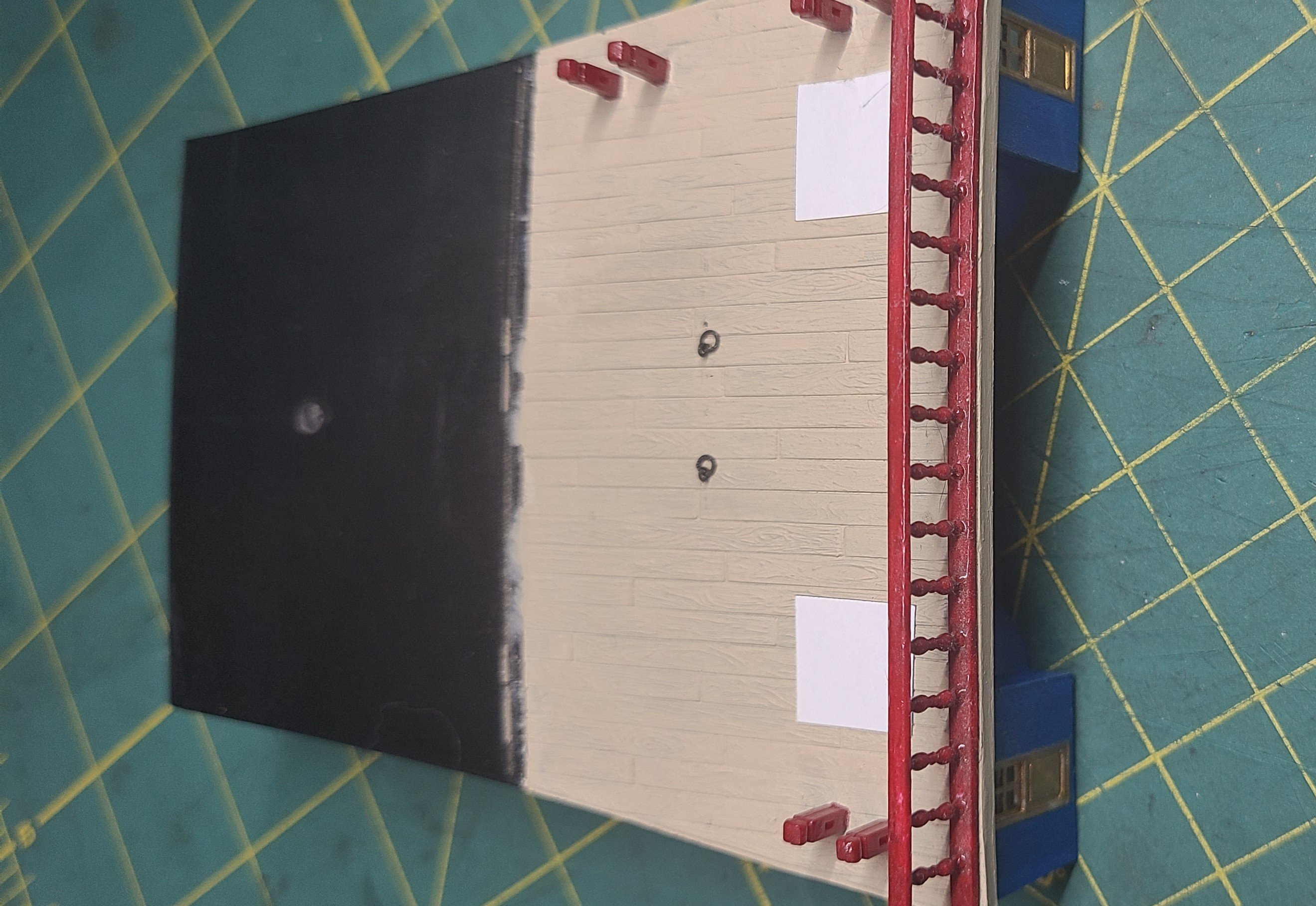
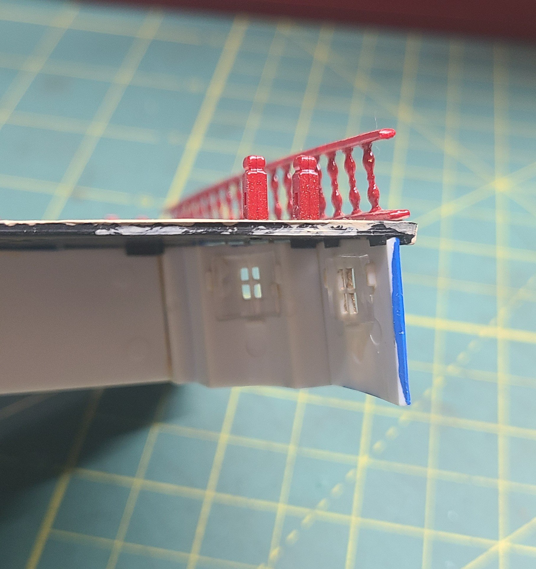
Sorry, I was a bit lacking in detail. Custom breast-rails.
I was considering cutting in a companionway and stairs with a rail surround in order to access the poop from within the quarterdeck house. The companionways will go where the white squares are in the picture below. The stairs will curve along the interior bulkhead in front of the small window and end next to the door to the quarterdeck. I will be removing the rail that is there and using the balusters for the companionway railings. It bothers me that there is no way to access the poop or poop-royal decks.
The area between the mizzen mast and the quarterdeck is too congested for an exterior ladder or stairs, especially with a cannon sitting where the bottom of a stairway would go.


Regards,
Henry
- Archi, Hubac's Historian, Bill97 and 3 others
-
 6
6
-
This is something that I have been contemplating doing for my build. As well as making internal access from below to the poop deck.
Regards,
Henry
-
Finally, my new officers sword baldric.
The back story:
The current person portraying an officer in our unit has decided to step down. The next person in line for the position is me. Therefore I have had to start the process of acquiring and/or making a new officers uniform for myself. It is not an easy or inexpensive project. The wool and other materials have to be authentic and the tailor has to be familiar with period tailoring construction and techniques.
Here is a breakdown of the items with cost.
Chapeau Bras (hat) $400
Wool for coat $900
Waistcoat $150
Trousers $100
Hessian Boots $1000
Sword $350
Sash, Epaulets, Braid, Buttons, etc. $300
Seamstress/tailoring fees $?? not done yet.
To date I have the wool, the trousers, the sword, and all the small accessories. The waistcoat is in progress with the seamstress. The hatter is completing my chapeau bras. It is going to take some time for fittings and such for the tail coat. But, the Hessian boots are currently stuck in France.
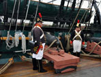
That brings us back to todays topic. I have completed fabricating the sword baldric.
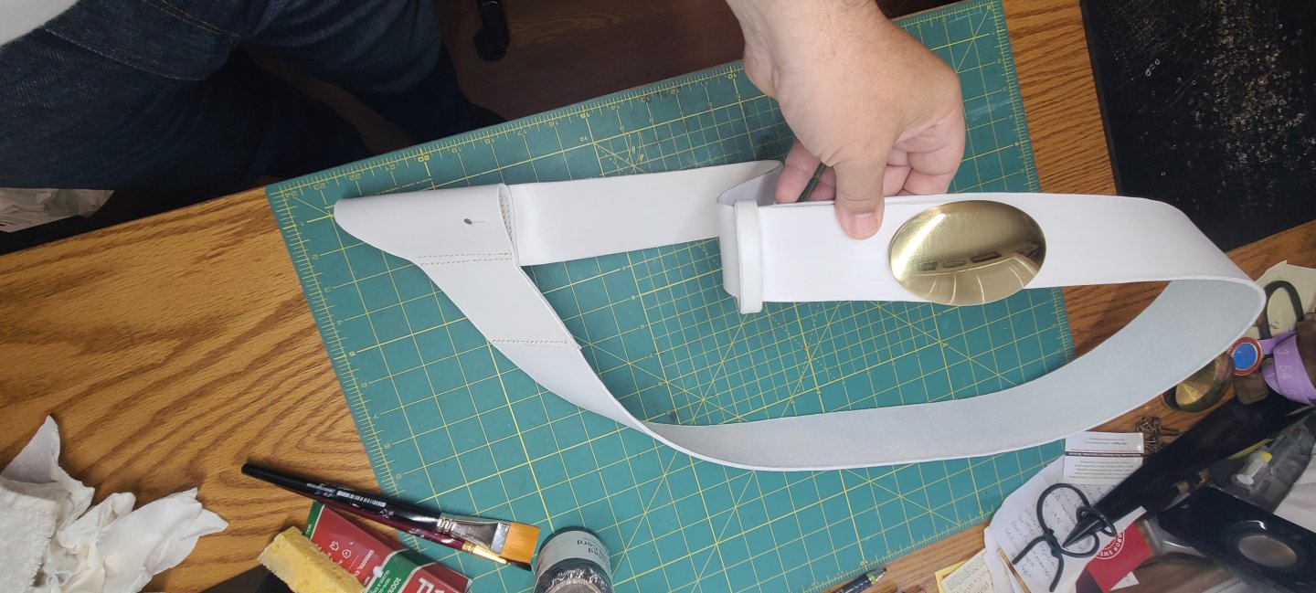
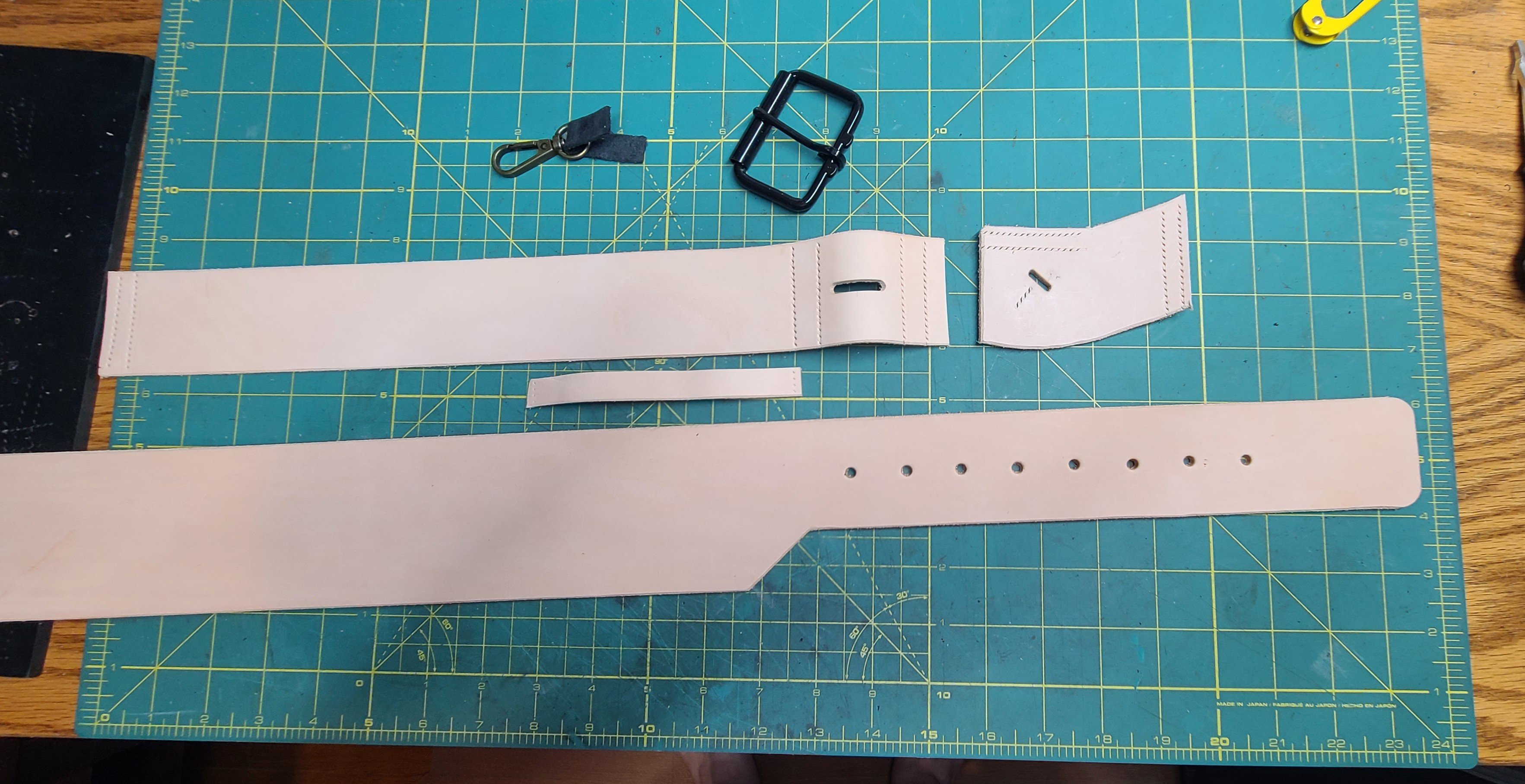
Here it is
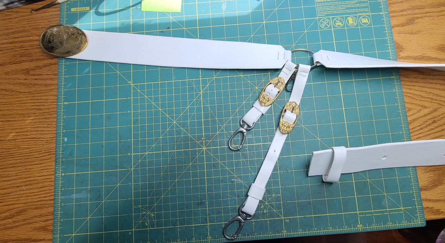
The fittings, from left to right, are all stitched to a central ring that hangs at my left hip: Breast plate, front sword hanger, hook, rear sword hanger, shoulder strap.
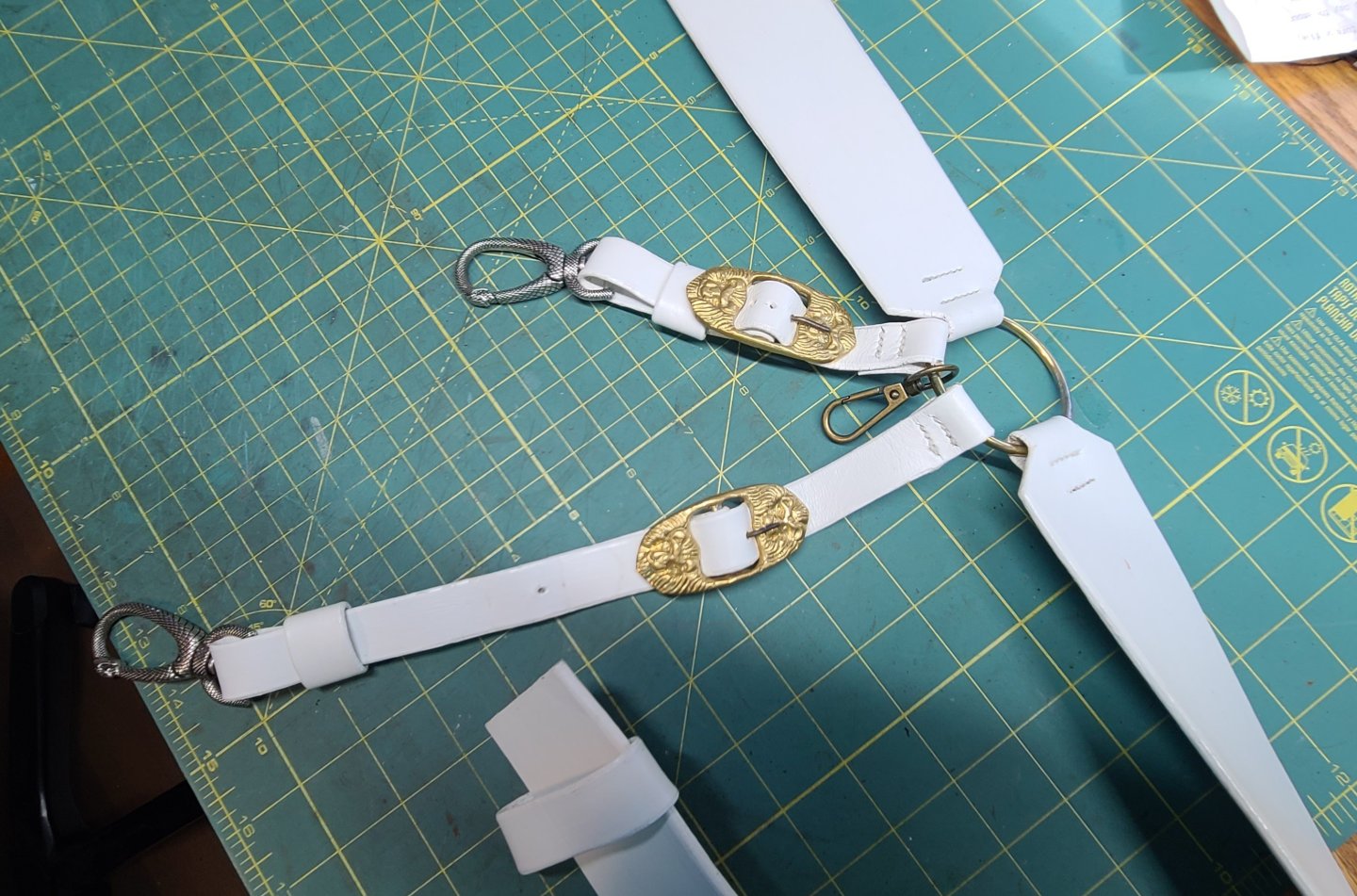
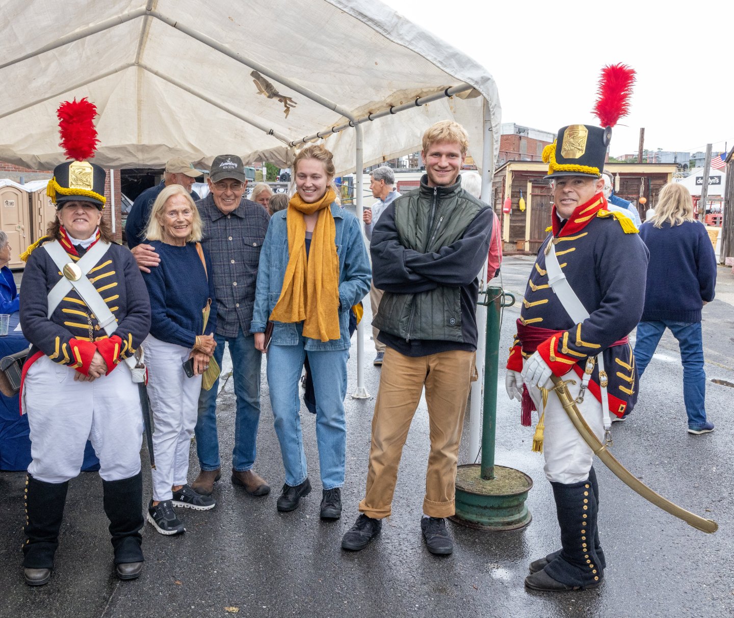
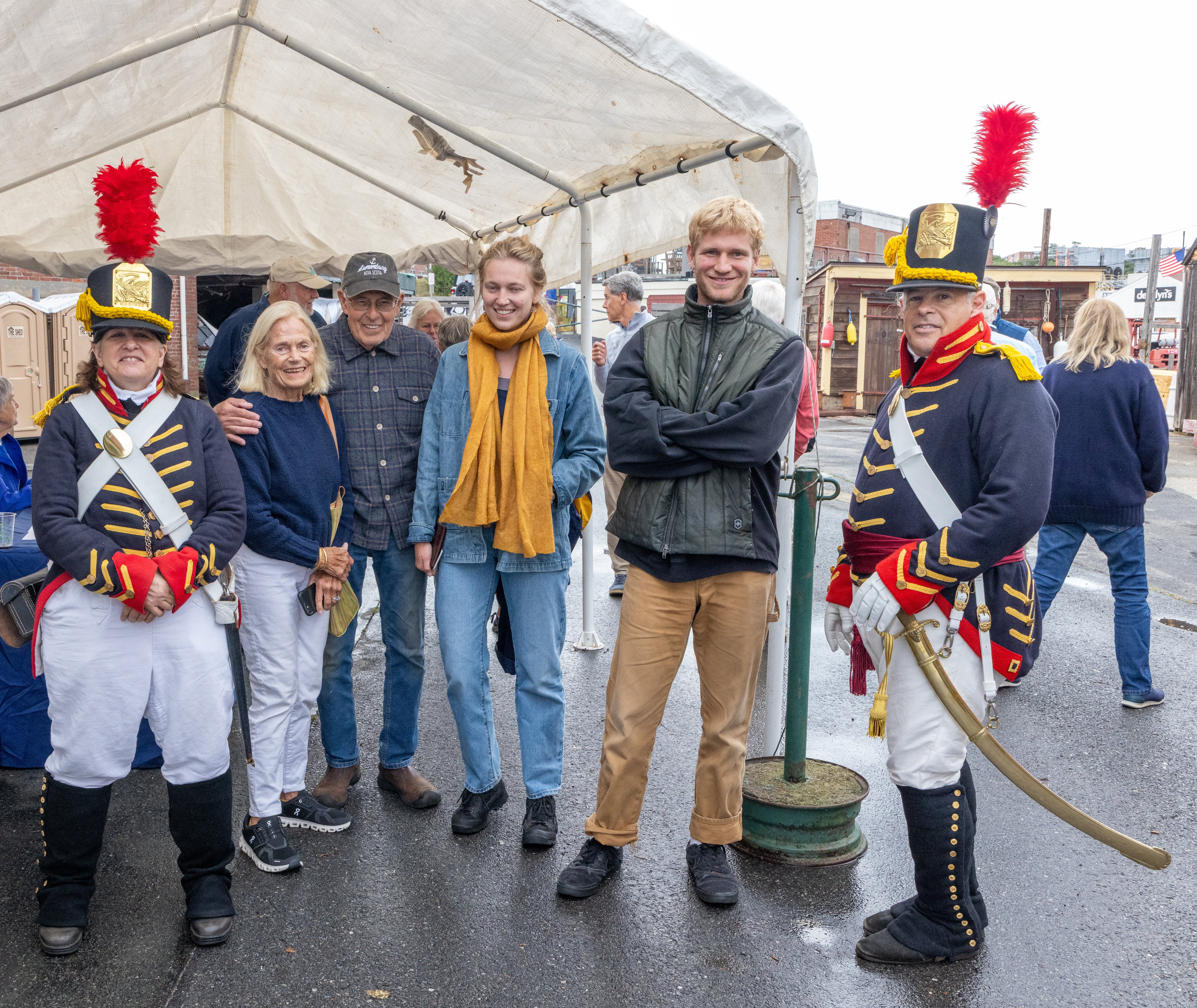
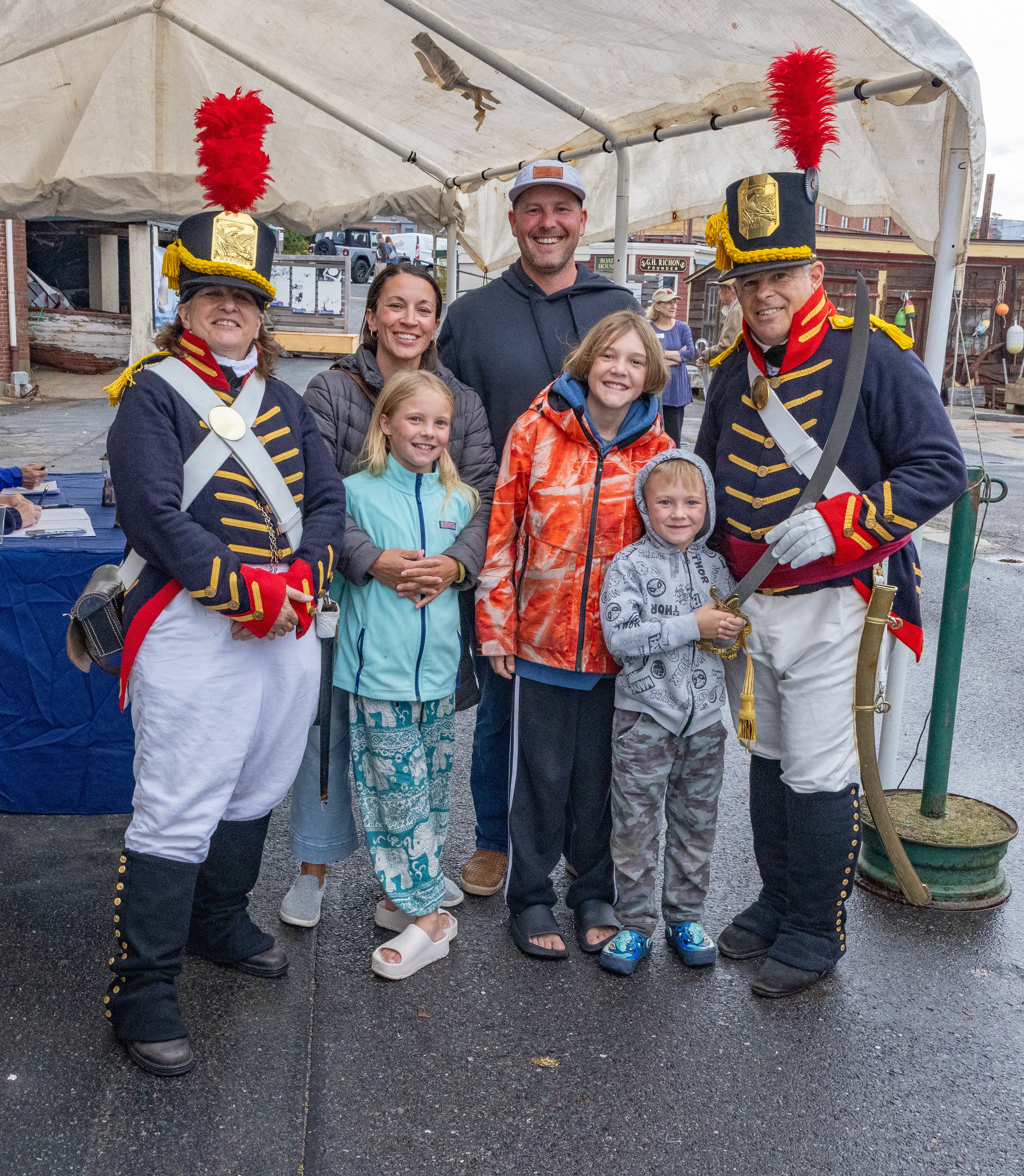
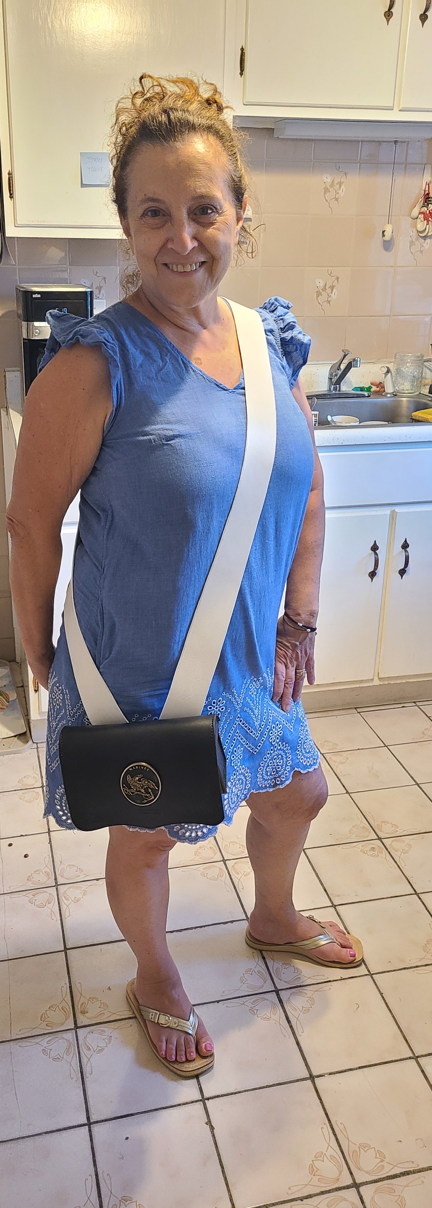
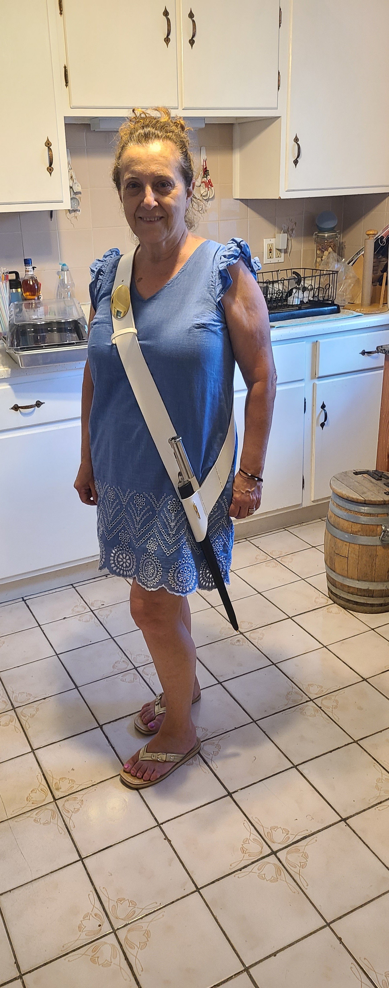
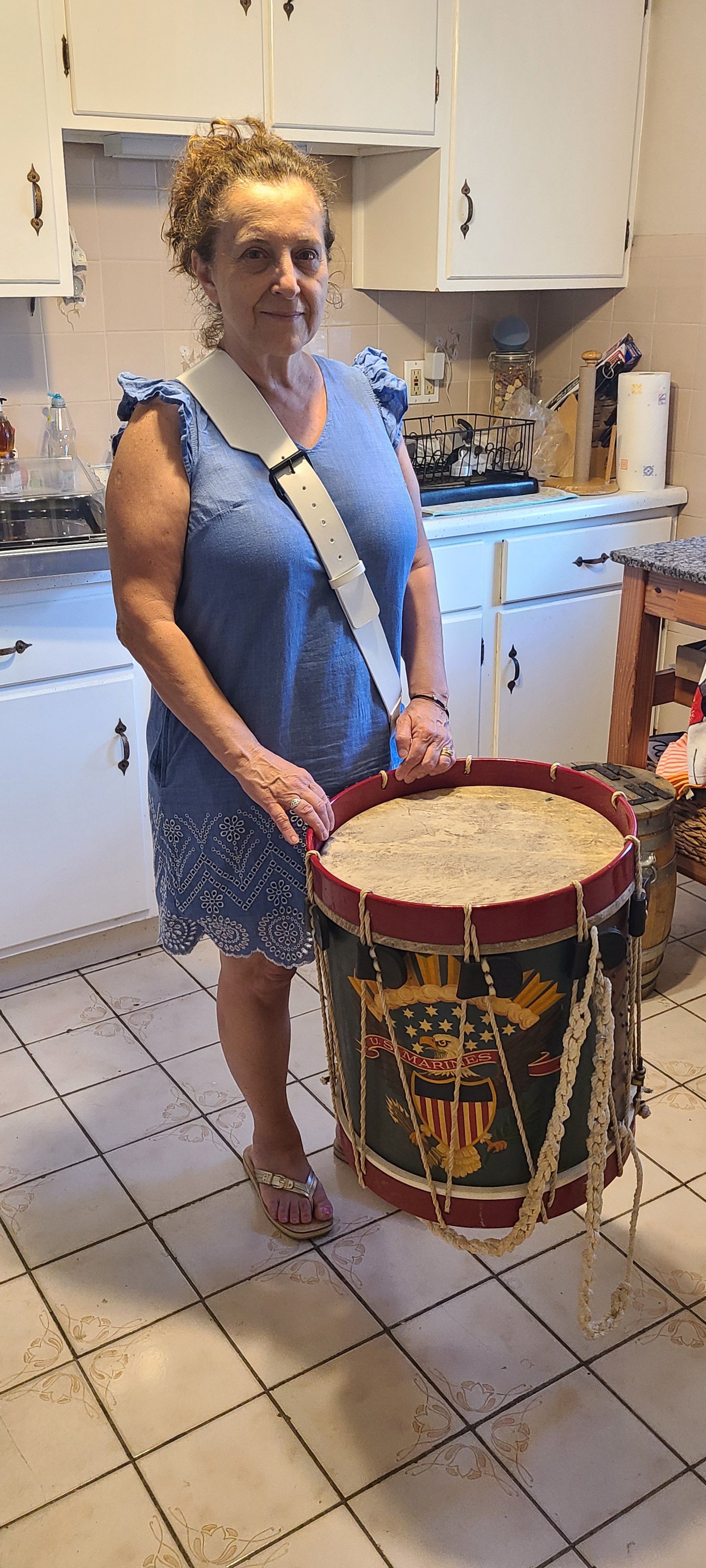
Here are some photos from an event last weekend showing how it is worn. In the interim between when my officers uniform is complete and now, I am portraying what , in the era, was called an orderly sergeant; a sergeant who was in command of a ships detachment of marines. I am, therefore, authorized to wear the sword and the sash denoting command. When the new uniform is complete I will switch over to portraying a captain of marines.
In this next photo is demonstrated the use of the small hook that is installed between the two hangers. When 'in use' the scabbard depends from the hangers at an angle convenient for drawing the sword. When not in use the scabbard can be reversed and hung from the small hook. This allows the sword to hang more vertically along the left leg making it more comfortable to walk about without the sword banging around your legs.
One more note: the decorative gold and red sword knot on the hilt of the sword actually has a function. The sword knot is composed of a long loop of braid with a tassel on the end which is knotted and wrapped around the guard. When in battle the hand is passed through loop of braid so that if the sword is un-handed it will remain hanging from the wrist and not be lost.

That concludes the current leather work projects for the 1812 Marines. As new people join the unit I will make items as appropriate.
I do not have any orders yet for neck stocks or fatigue hats, but those were also made of leather and I do have patterns made for them.
Until next time.
Regards,
Henry
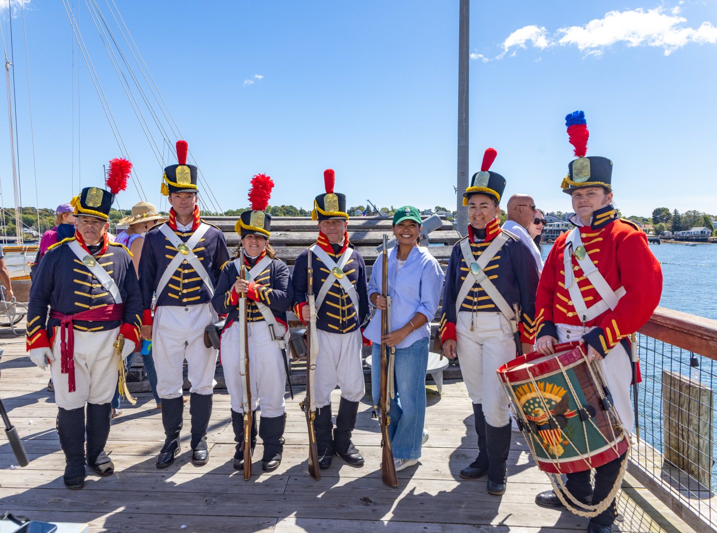
P.S. on the right is my drummer who is wearing his new snare drum hanger and sword baldric!!
-
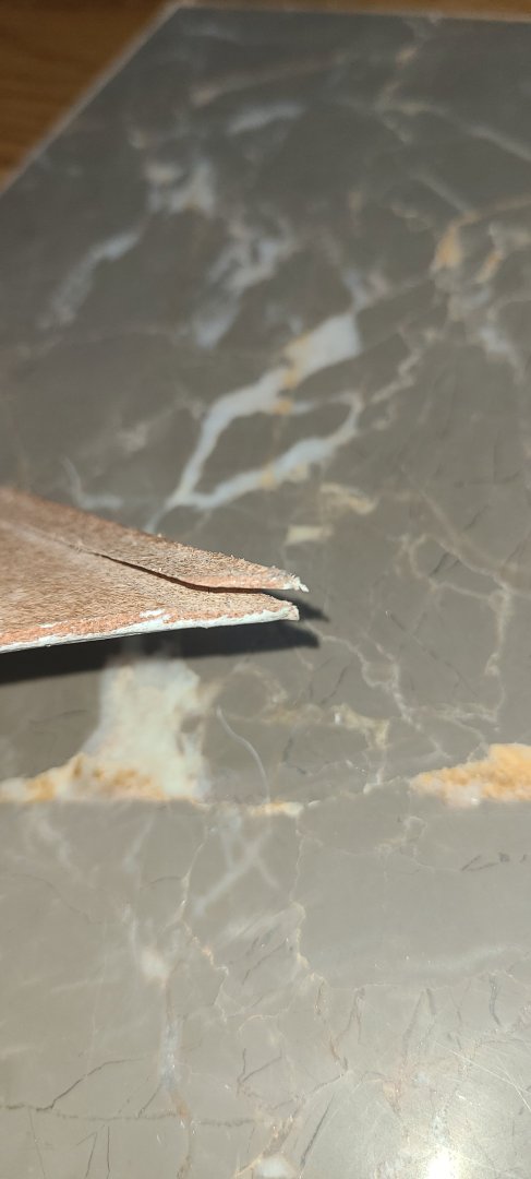
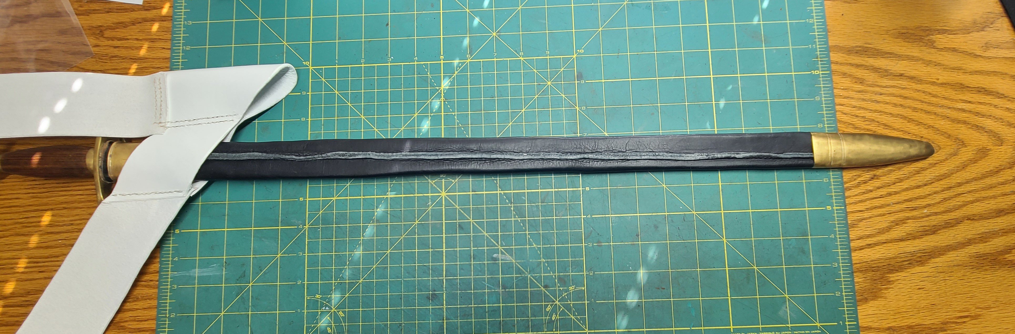
New sergeant scabbard.
You can see in the picture of the old sword scabbard that the leather is old, dried out, cracking, and falling apart.
Here is my first attempt at a replacement scabbard.
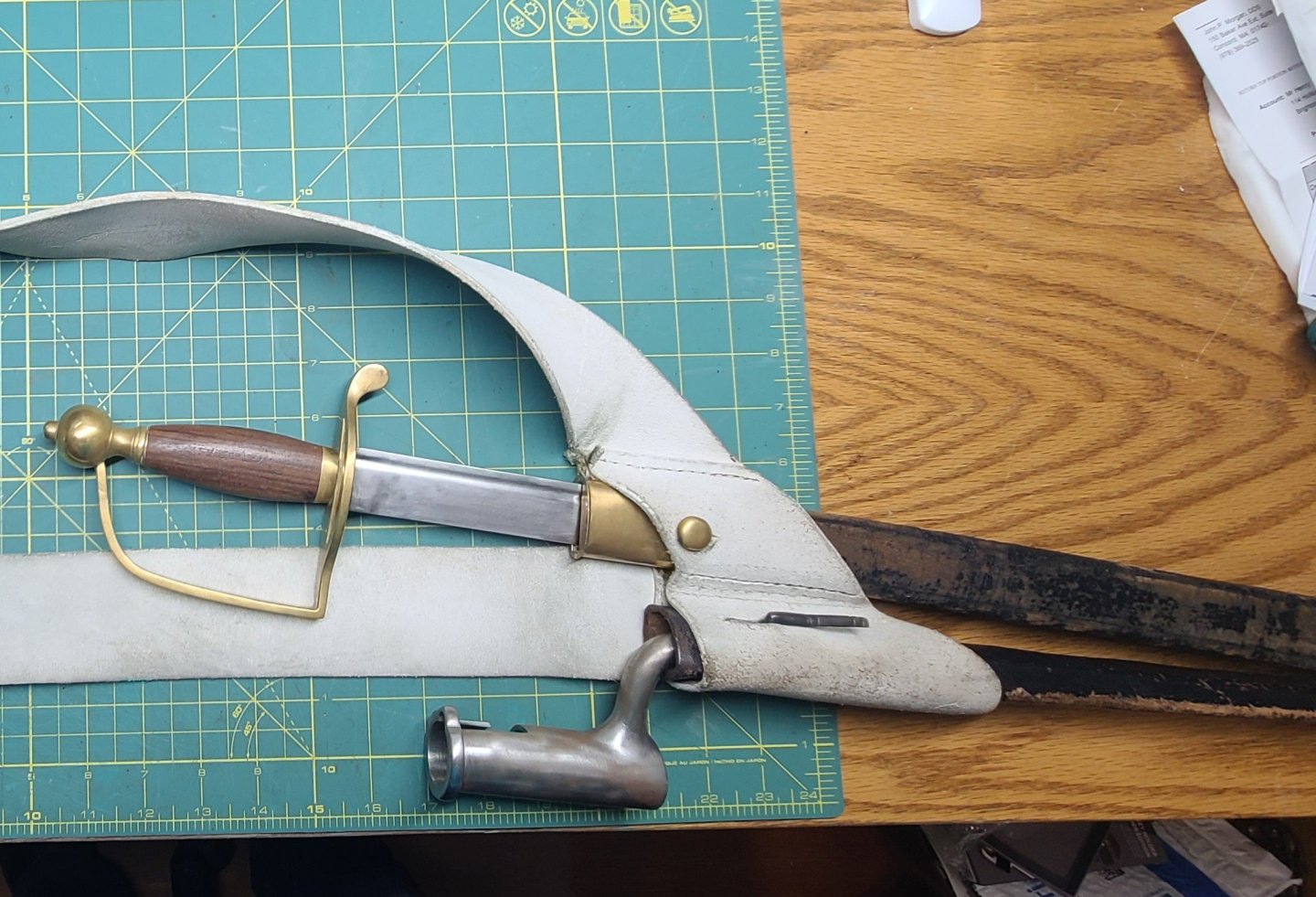
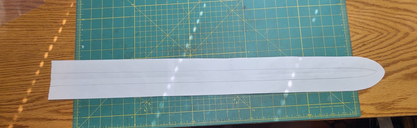
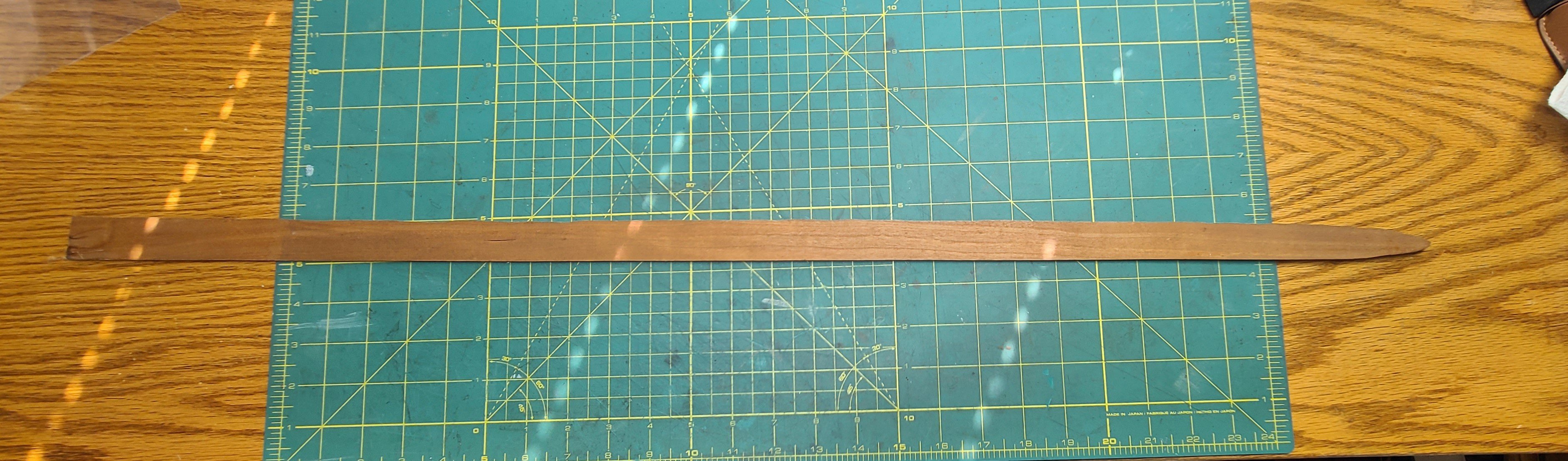
First the pattern is made by tracing the sword onto paper. An allowance is added on either side for the width of the blade plus a seam allowance for stitching. Then a wooden former is cut out using the sword as a template. The leather is cut to the pattern size. I am using the same black leather that I used for parts of the cartouche box.
The leather is folded in half length wise, finished sides out and cut edges aligned, and contact cemented together. A single row of saddle stitches are run along the seam allowance from the throat to just before the tip. The scabbard is then soaked, submerged in water, for about 30 seconds. After soaking the scabbard is allowed to sit for about 5 minutes to allow the moisture to penetrate all of the leather. Then the seam is pressed down into the middle of scabbard, making sure it runs centered down the middle of the face. Then hammer the seam down with a mallet. Slide the former into the scabbard all the way to the tip. Ensure that the seam is centered on the face of the scabbard. Using an edge slicker, smooth down the edges of the seam. The hammering and slicking helps to get the seam allowance flattened out and tight against the face of the scabbard.
Now comes the pressing. In order to press the scabbard into its final shape I made a simple press out of two 1 x 2 pieces of wood. I cut a shallow groove the width of the scabbard seam into one face and then sanded the faces of the wood that would come in contact with the scabbard. Any imperfections in the wood will get transferred into the leather when you press the scabbard.
Place the scabbard into the wood press with the seam in the slot. You can add pressure by standing on the wood or you can use clamps. Press the scabbard down hard. Take the former out of the scabbard and press it again. Now one last press with the former back in.
Once the scabbard is pressed down hard, remove it from the press and check it to see if you have a good, clean, smooth, straight shape. Now you can let the scabbard dry, with the form in, 12 to 24 hours till completely dry.
To finish the scabbard, the brass throat and tip guards are press fit onto the leather.

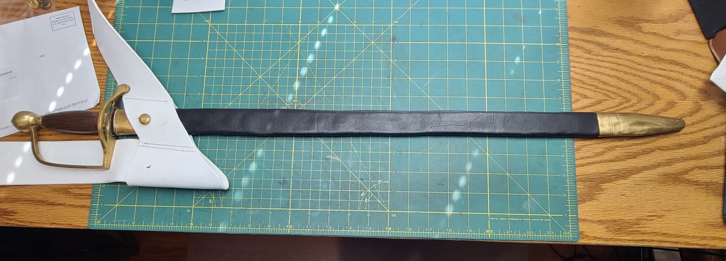
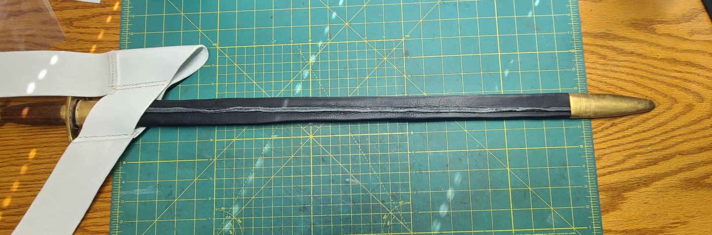
You can see with the last picture that the seam on my scabbard is not very centered all the way down. That is because the sword is not symmetrical. The back of the blade stays relatively straight and the cutting edge curves a bit more towards the tip. I tried to make the pattern do the same thing but when I formed the scabbard up it ended up twisting a bit. I am not going to redo the scabbard. The seam side is worn towards the body so it is less visible. I will, however, re finish the seam so it is a bit smoother and edge coat it so it disappears more against the face.
Regards,
Henry
-
-
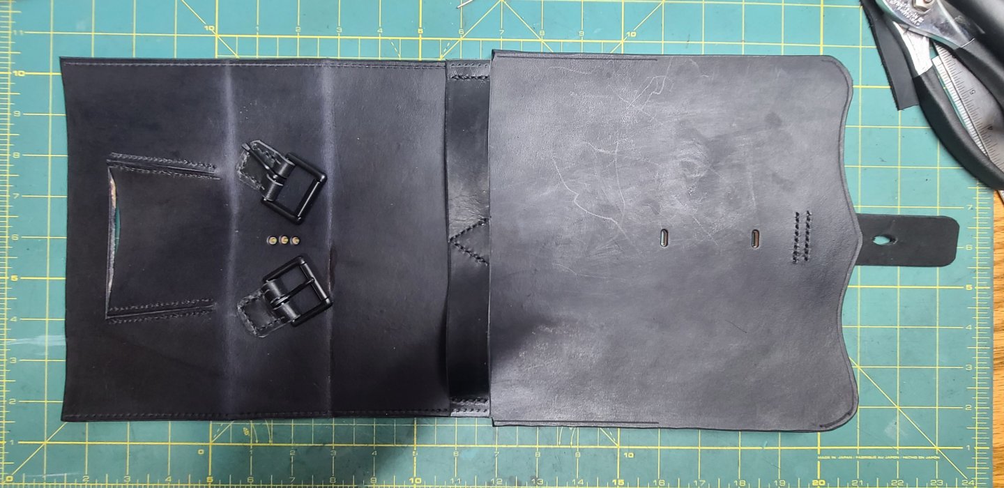
Moving on the the snare drum hanger.
I designed a pattern for and constructed a drum hanger. The pattern uses the same design as the scabbard baldric except it has a different frog to hang the drum and a wider shoulder piece. The buckle is added to make the sling height adjustable. The snap hook is the attachment point to the drum and the short black strap on the hook is passed through the slot in the frog and cemented and stitch to the inside of the frog.

Regards,
Henry
-
Final assembly of the cartouche box.
In order to stitch the sides and end pieces into the box, I use a different stitch; the box stitch.
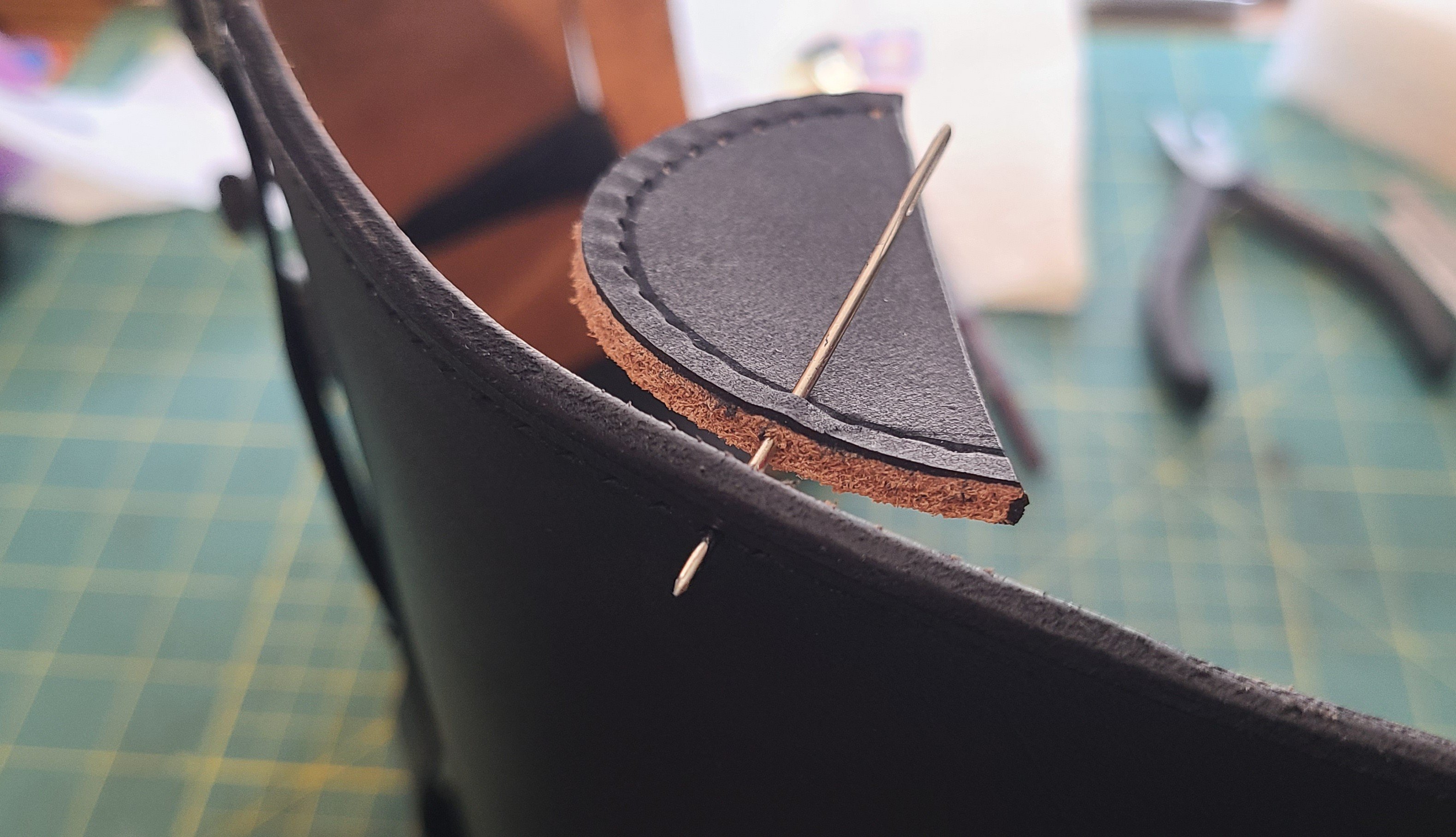
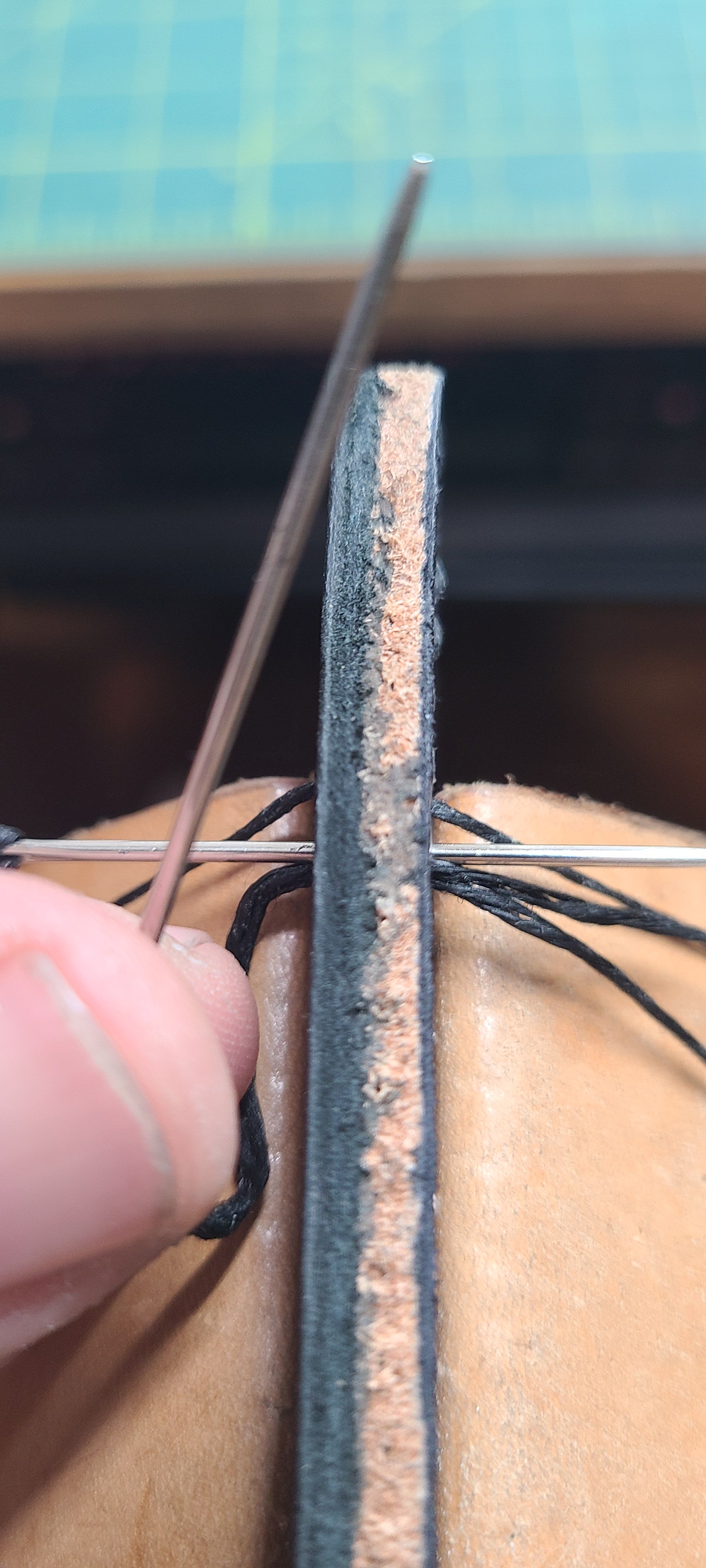
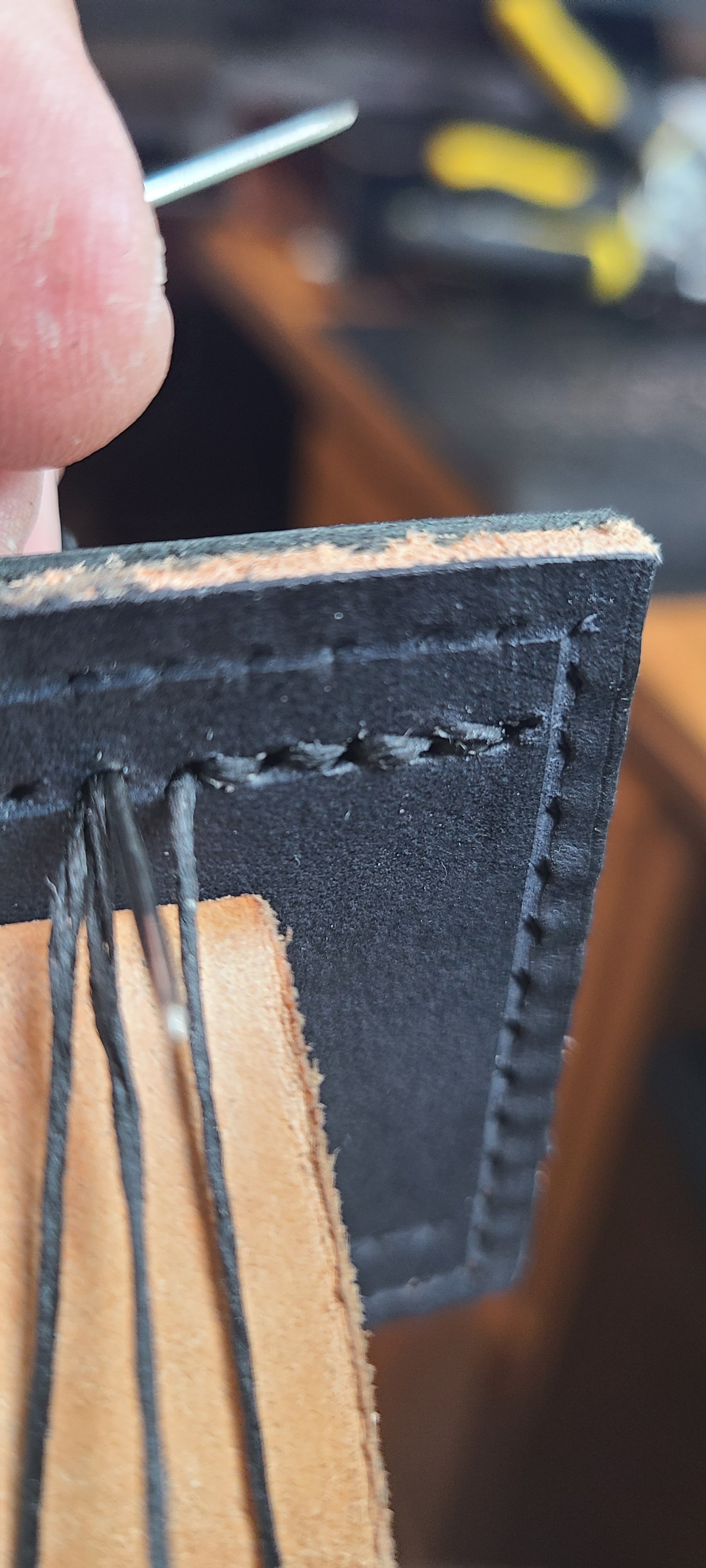
The box stitch is different from the saddle stitch in that instead of the two pieces lying flat on top of each other one piece is stitched end to. In order to do this the holes are punched differently. On the piece that will be standing on edge, the holes are punched so that they pass through the edge grain instead of through the back face. You can't just punch the holes with a stitching chisel, eight at a time. Each hole has to be made with an awl one at a time, being careful to push the awl through at the right angle to come out of the edge in the right spot. It takes practice. (Once again, being the first iteration of this type of piece, mistakes were made).
These photos are of the end caps for the box cover being stitched into place.

The sides of the box were stitched into the box in the same manner for the final assembly
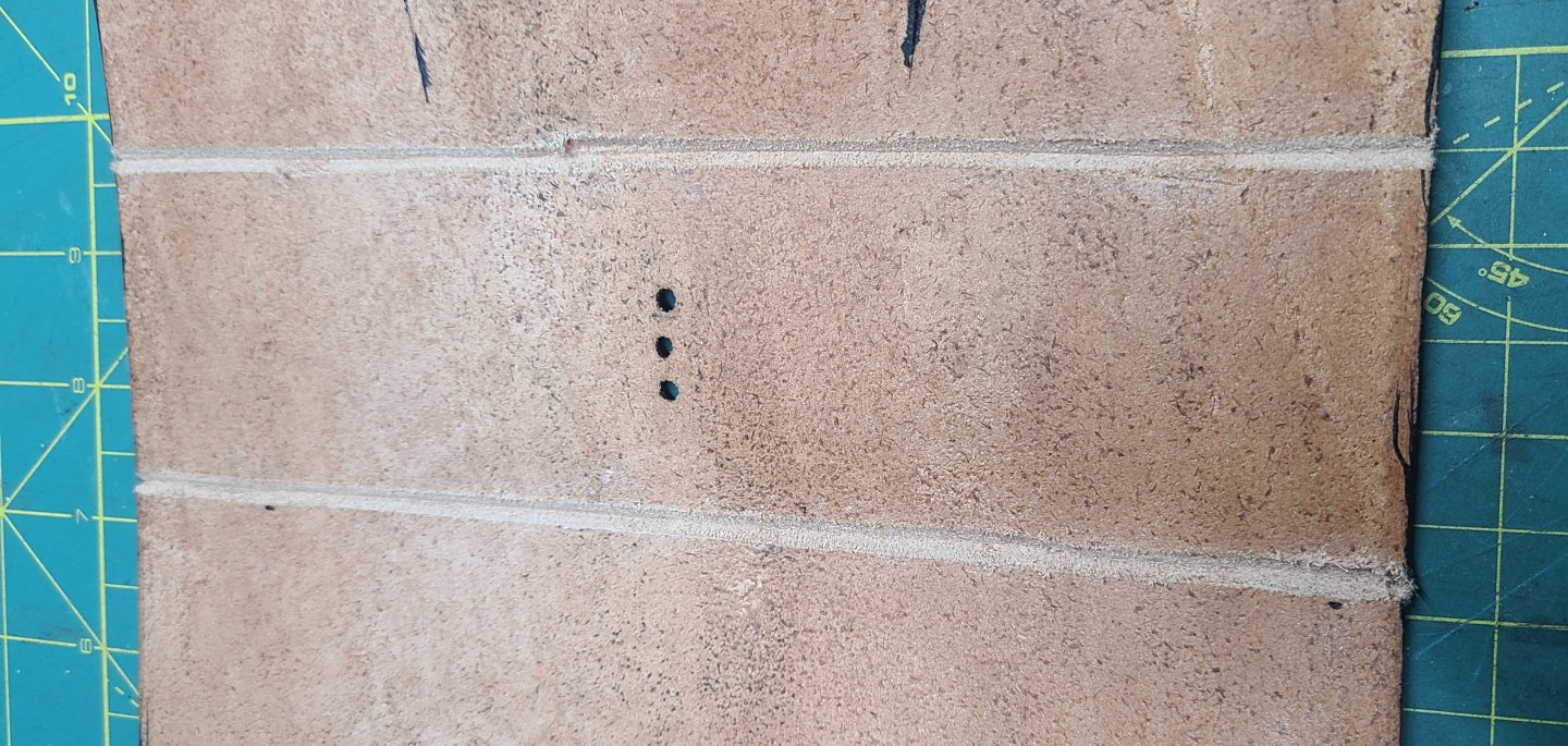
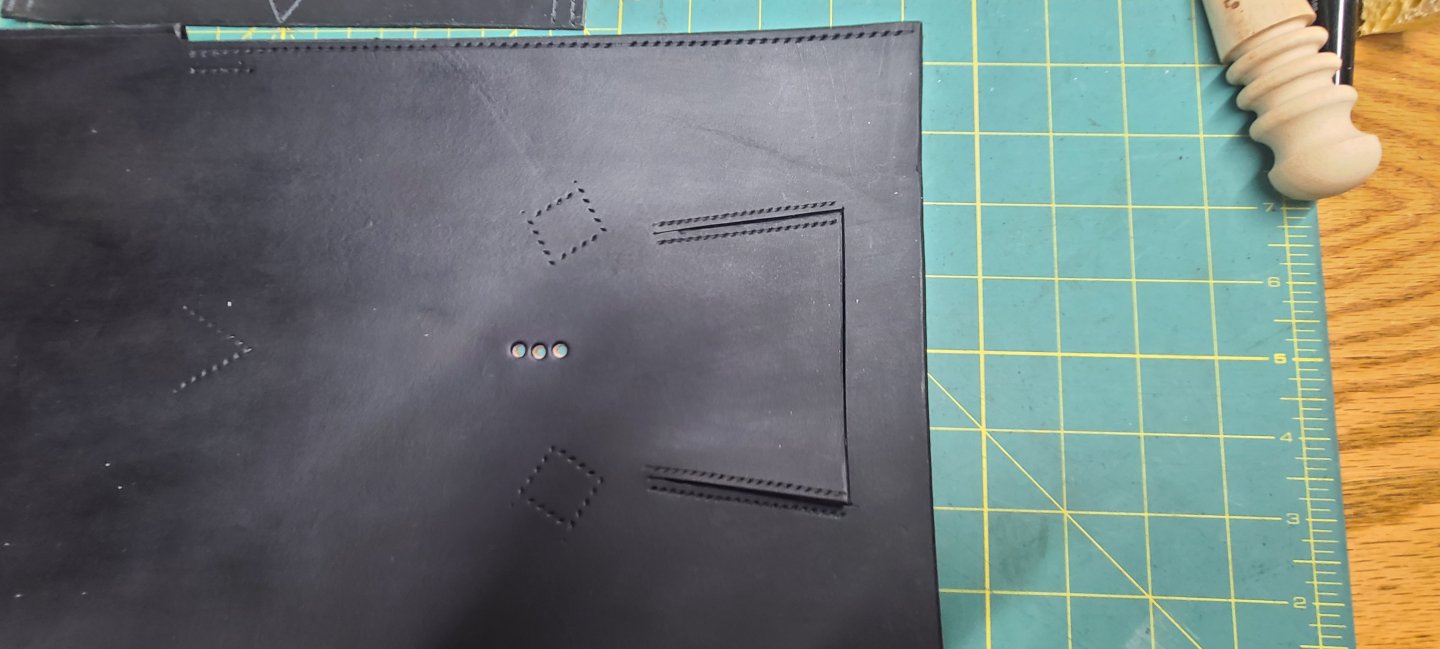
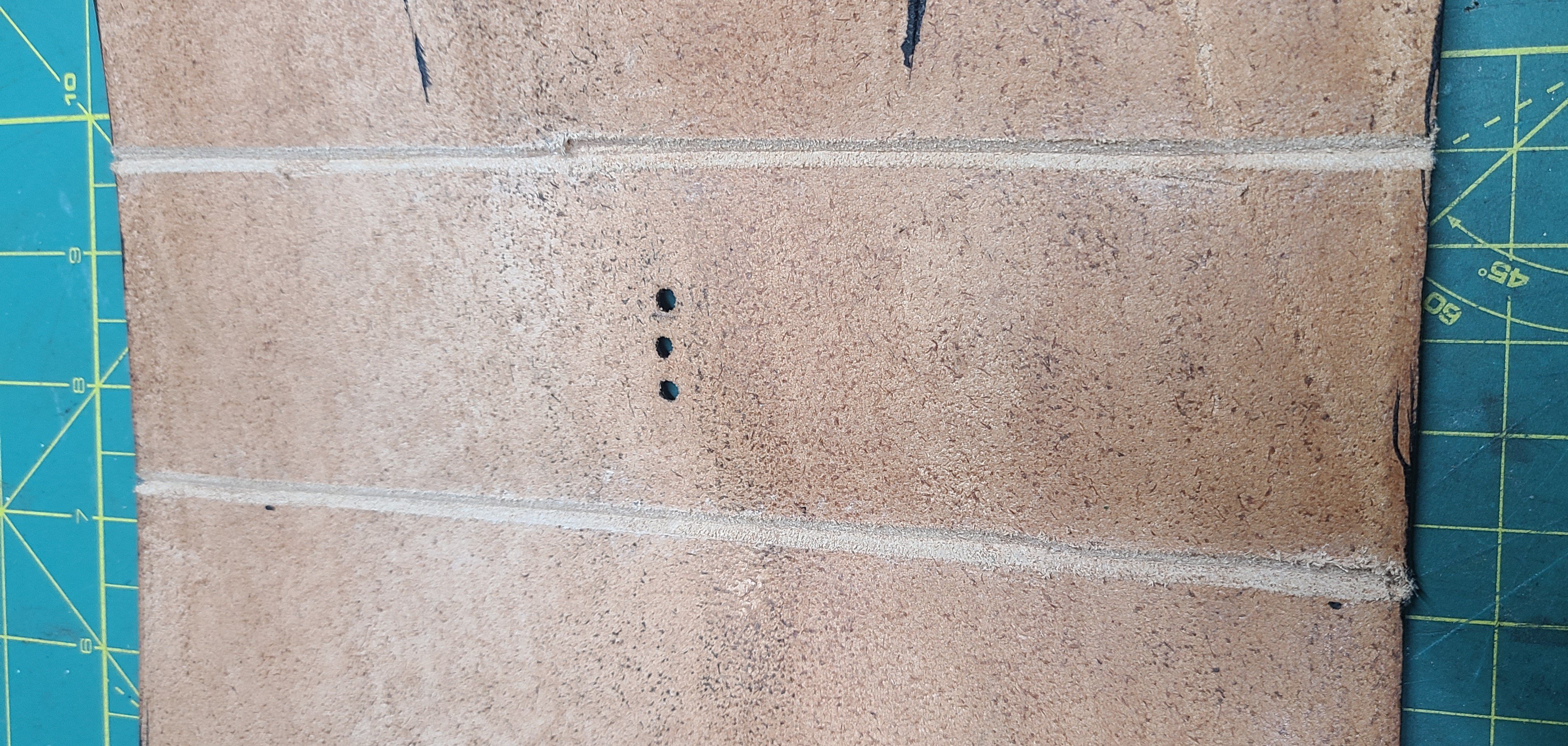
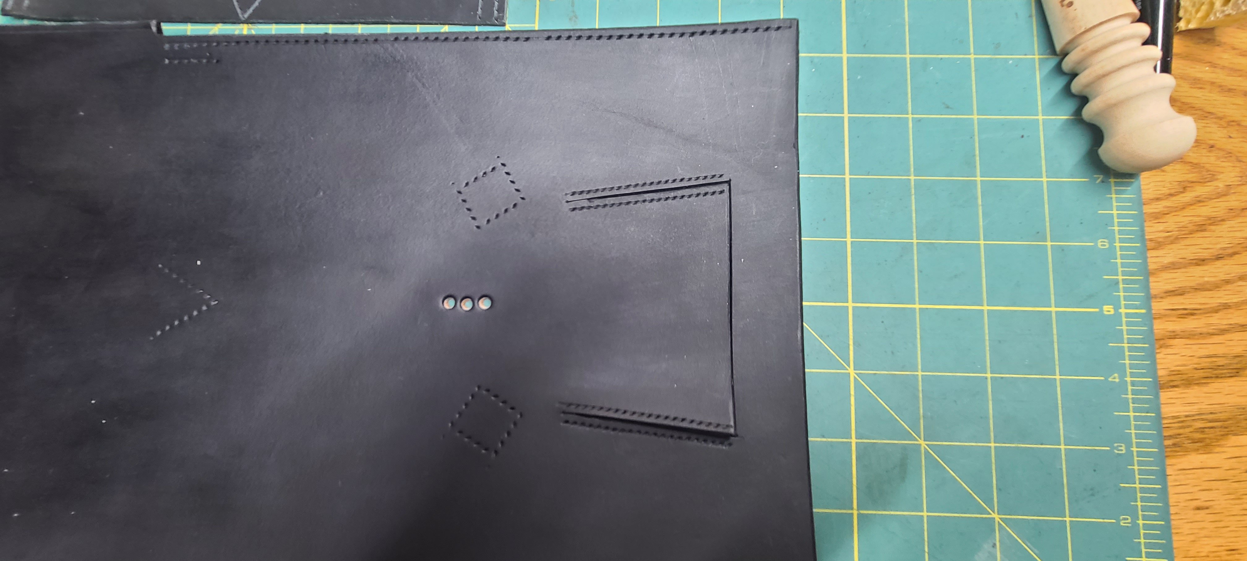
One last item that I forgot to take a picture of is the leather toggle for the box closure. It consists of a strip of thin leather that is narrowed at one end and rolled up to form a toggle. The dimensions of the strap are determined as follows. The width of the strap will determine the length of the toggle. The diameter of the toggle depends on the length of the strap from the end to where it narrows. You can figure out the size your toggle needs to be by the size and shape of its corresponding hole in the closure on the bag.
The portion of the toggle strap that is cut narrow passes through a slot cut in the larger end and holds the rolled up toggle. The toggle strap should be sized to fit the holes in the bottom of the cartouche box. (Those are the three holes punched in the bottom of the box seen in previous posts).
I know it is hard to envision how the toggle is made, but there are YouTube videos if you are interested.
After the toggle is formed, the narrow strap is passed through the three holes in the bottom of the cartouche box leaving enough length to toggle through the closure. A bit of contact cement is used fix the toggle strap to the inside of the box.
Regards,
Henry
-
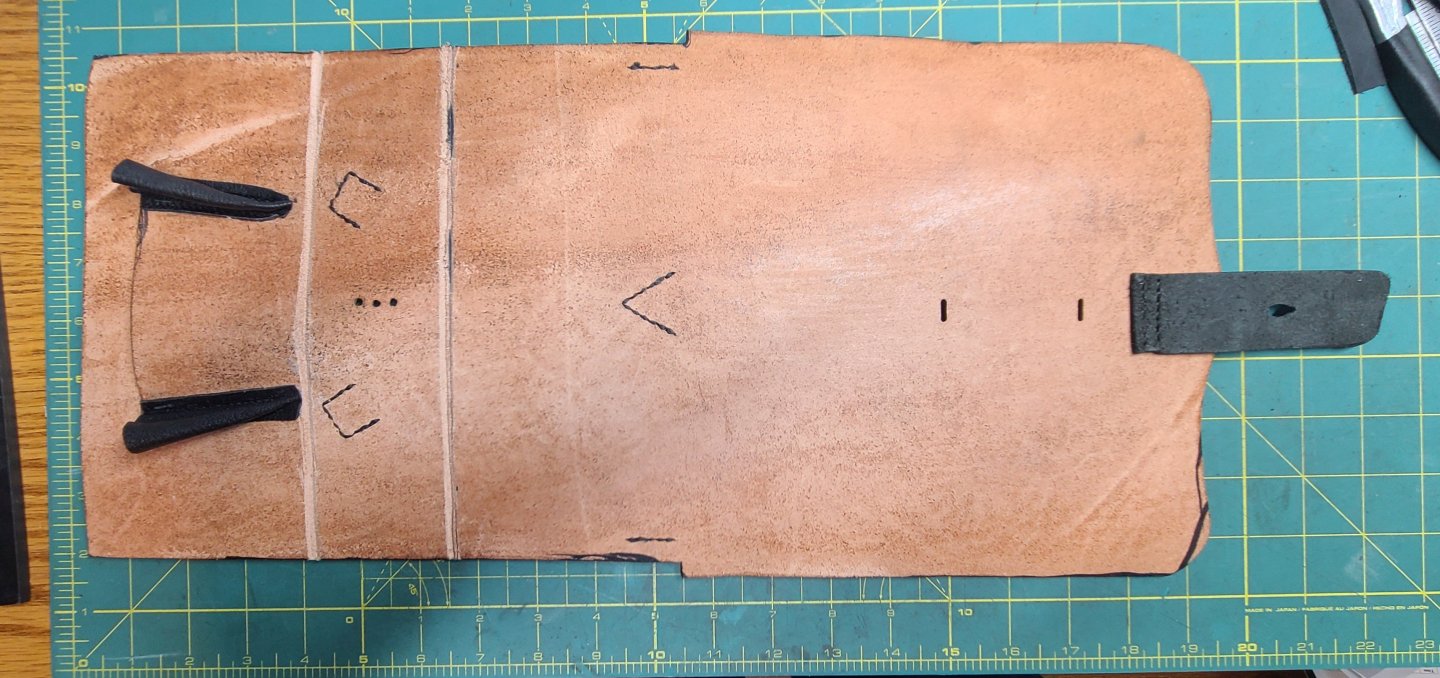
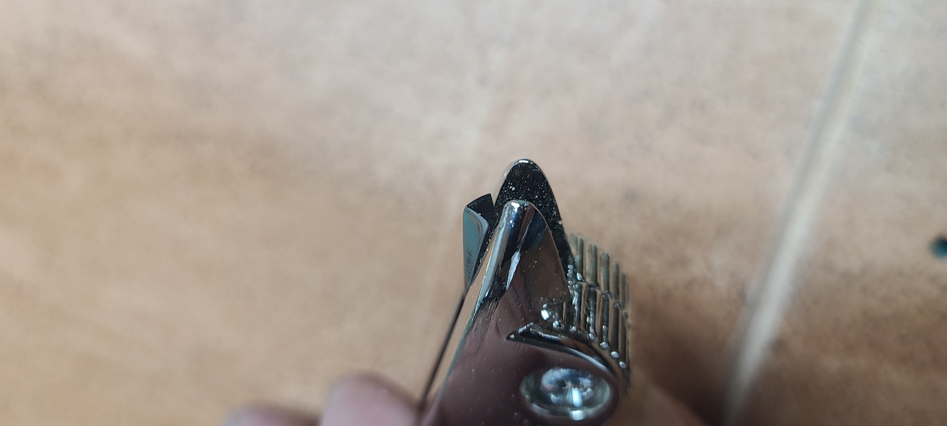
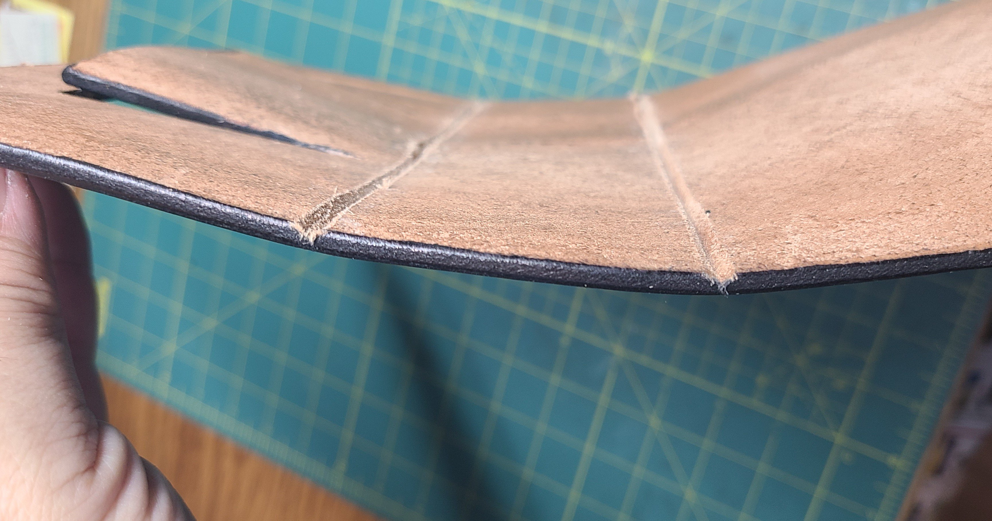
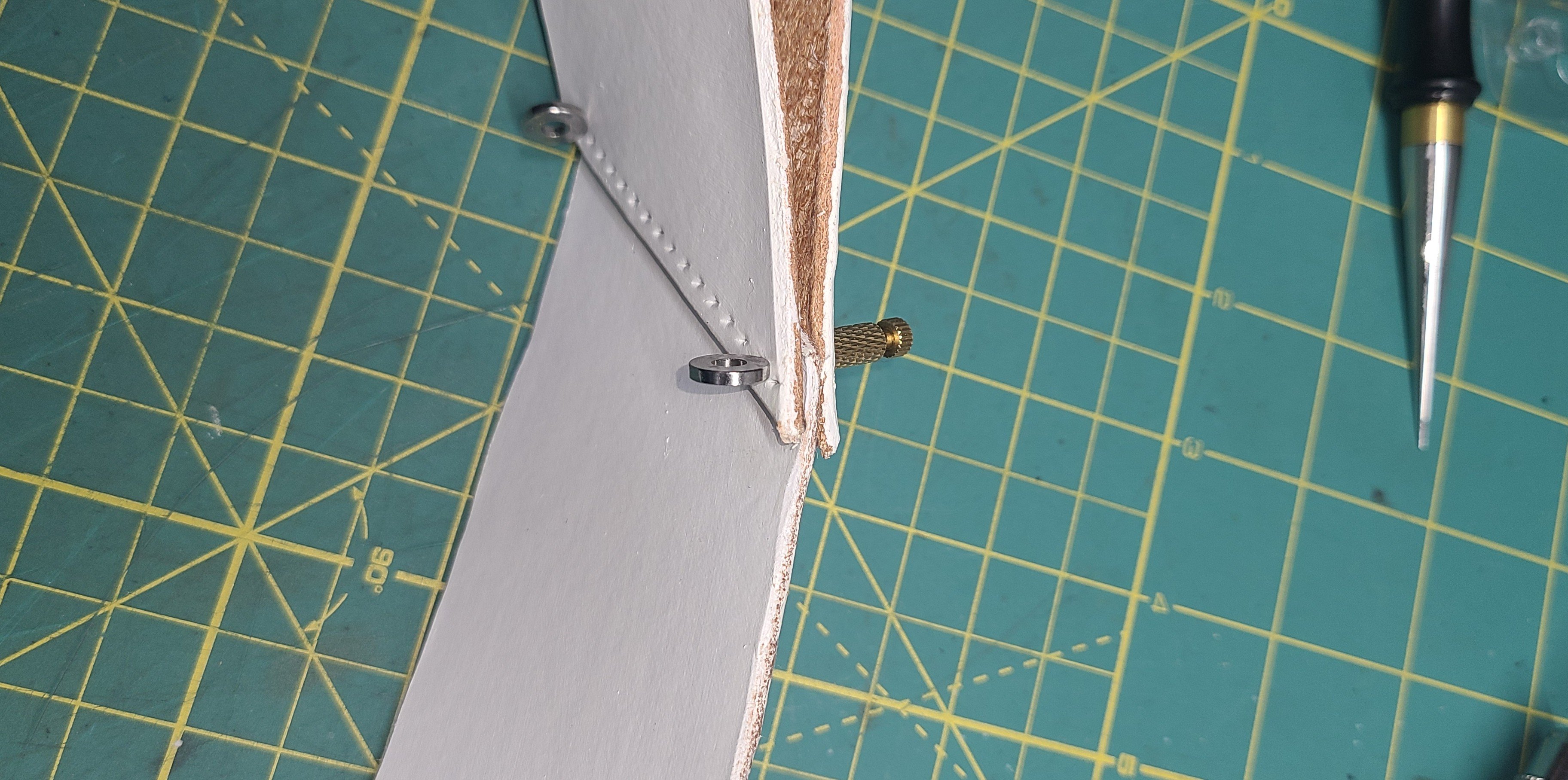
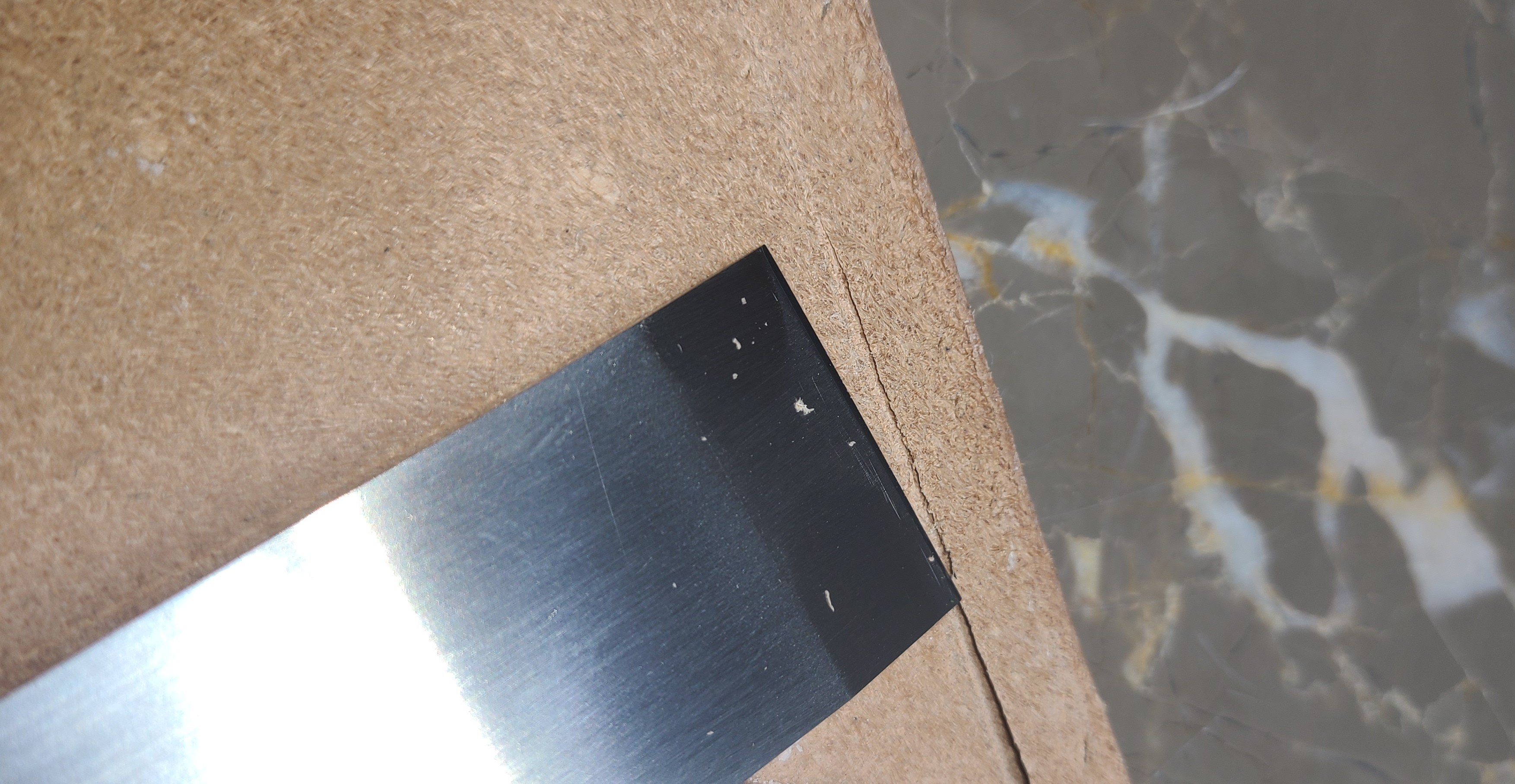
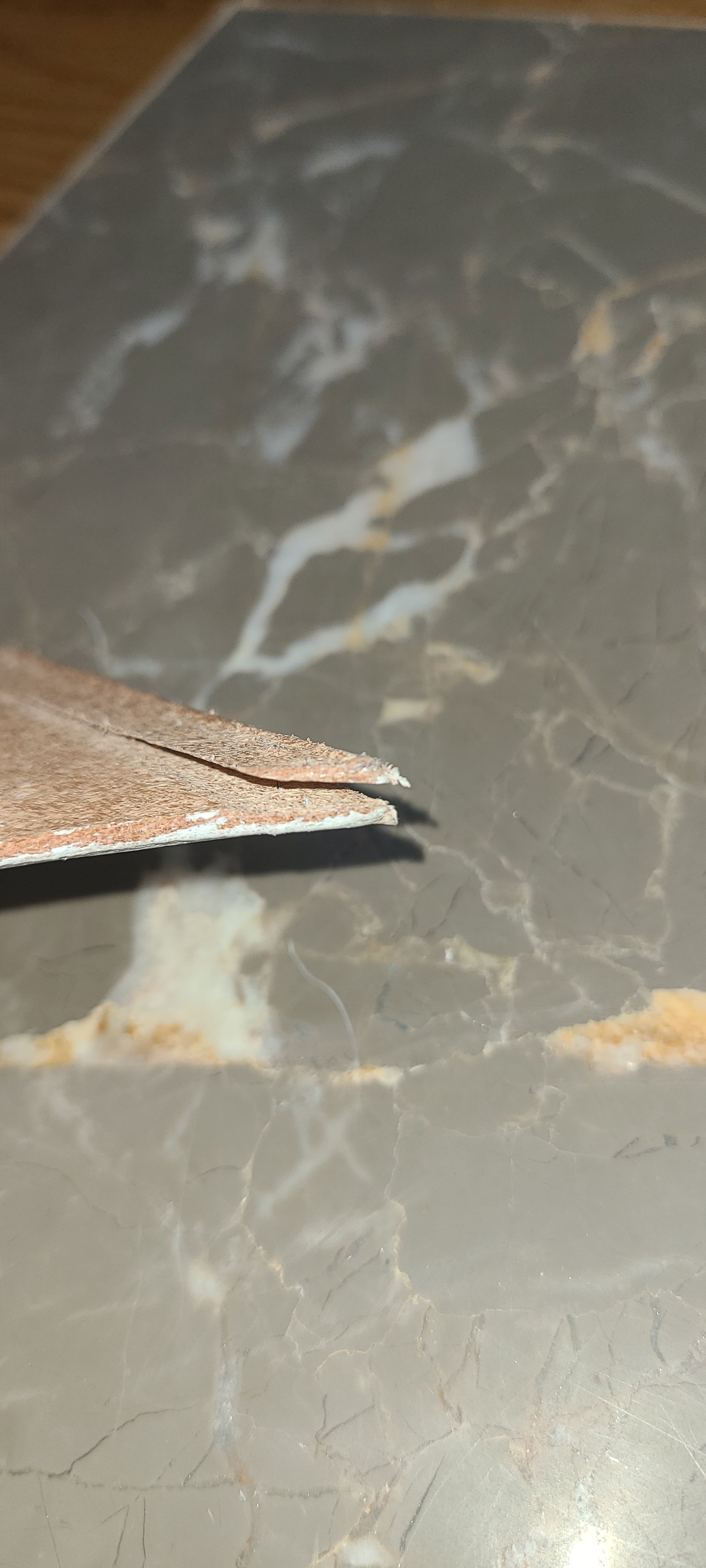
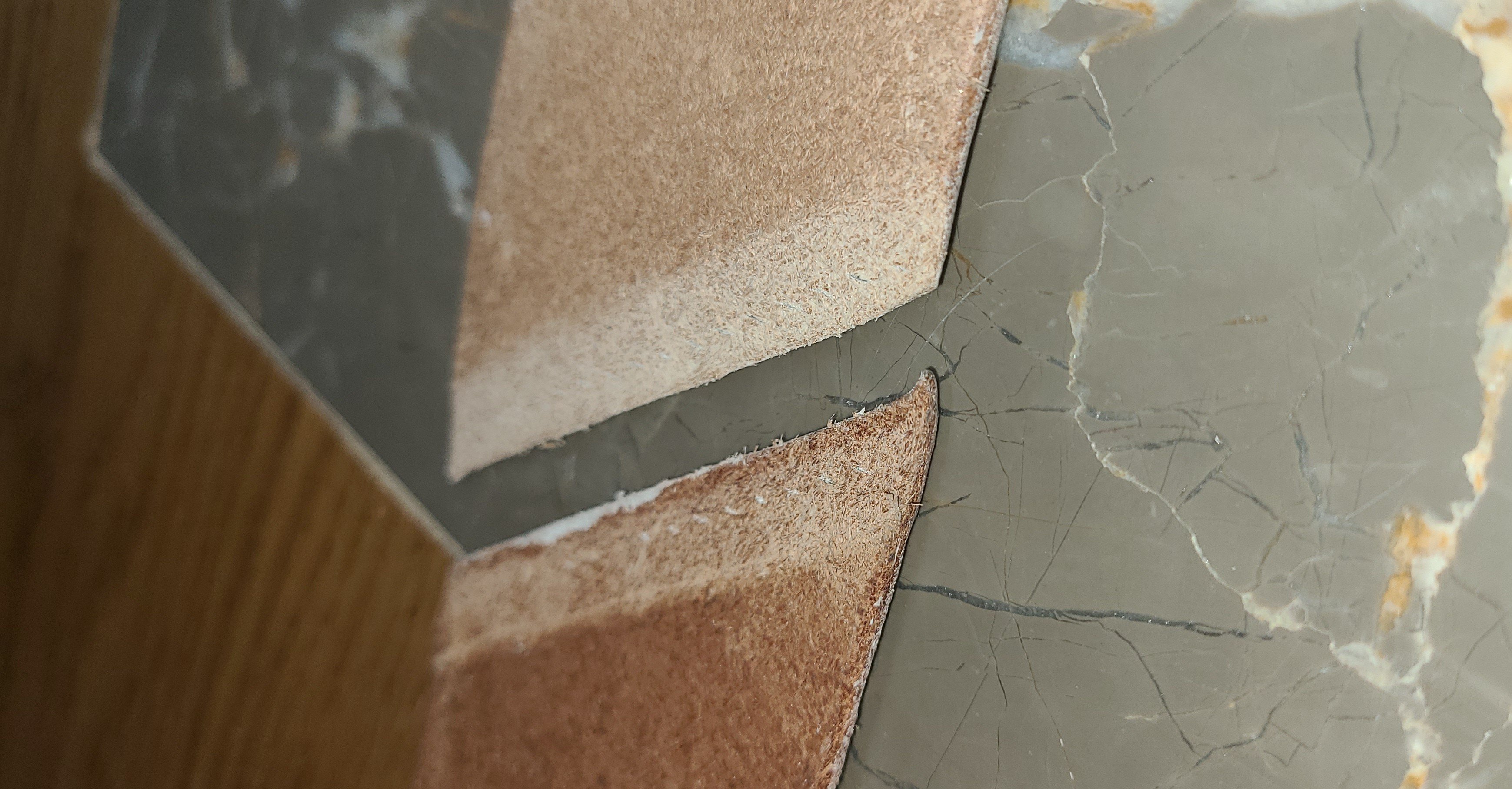
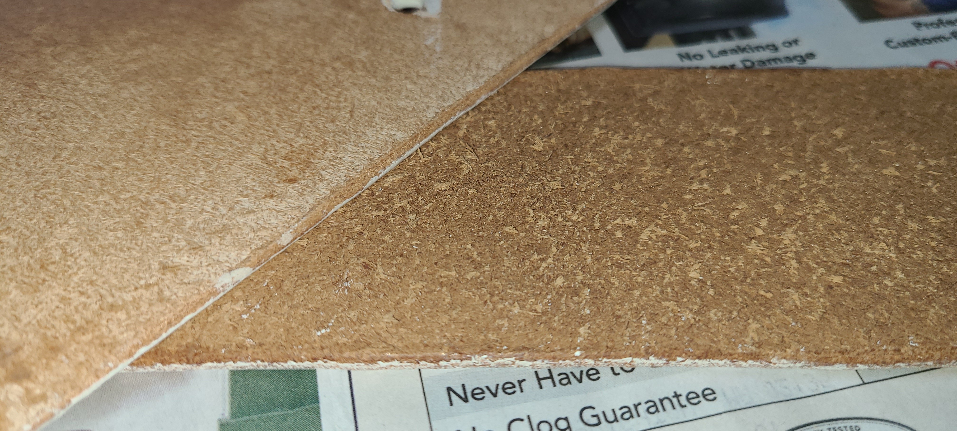
Before I can finish assembling the cartouche box it must be folded into shape. To make that possible, two grooves have to be cut to form the bottom of the box. I bought another new tool, the v-shaped groover, to accomplish this. While it is not a difficult tool to use, it is a bit nerve wracking getting the groove deep enough to fold the heavy leather, but not go through the whole piece to leave a gash in the finished side.
( I was not entirely successful in this. Luckily the small gash is in a spot that will be covered by the cross belt. This was my first attempt at a cartouche box. Mistakes were made.)


The various pieces are stitched on to the body of the box.
Regards,
Henry
-
Back to the Cartouche box.
Here I have dyed all the pieces black.

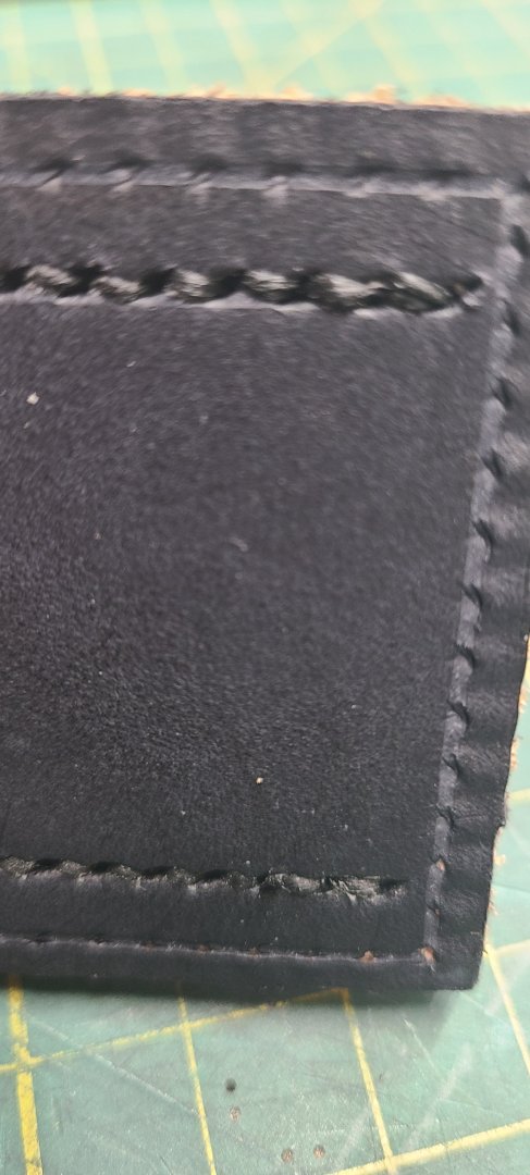
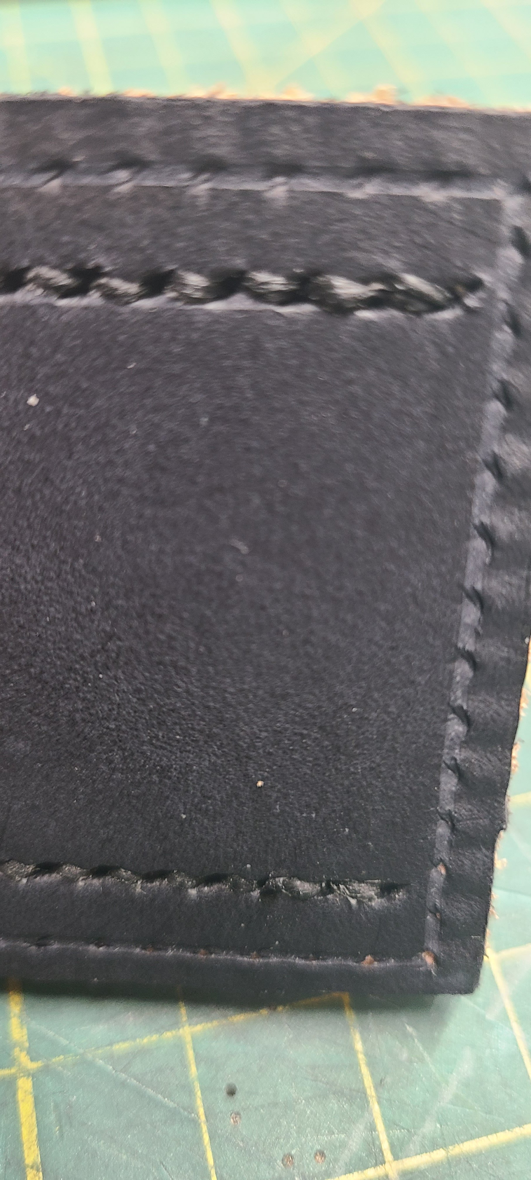
Starting to stitch the parts together. After the stitching is done the finished seam is tapped down with a leatherwork hammer. The hammer has a highly polished, slightly convex face. Tapping the seam down sets the row of stitches down into the stitch groove and closes up the hole so they don't have that puffy, ragged look that you get after stitching.


Regards,
Henry
-
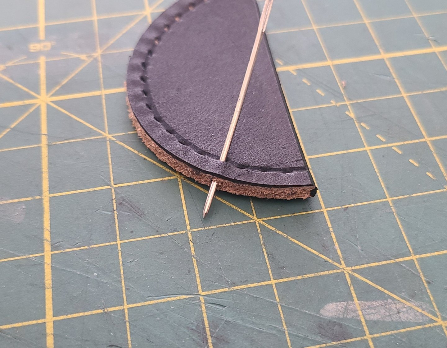
Next up is stitching up the baldric.
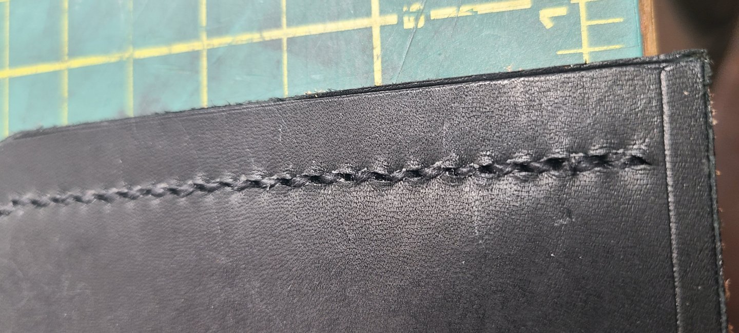
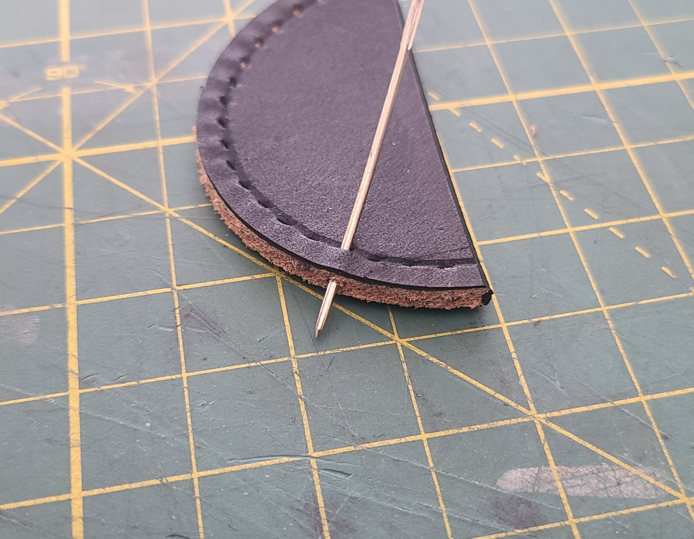
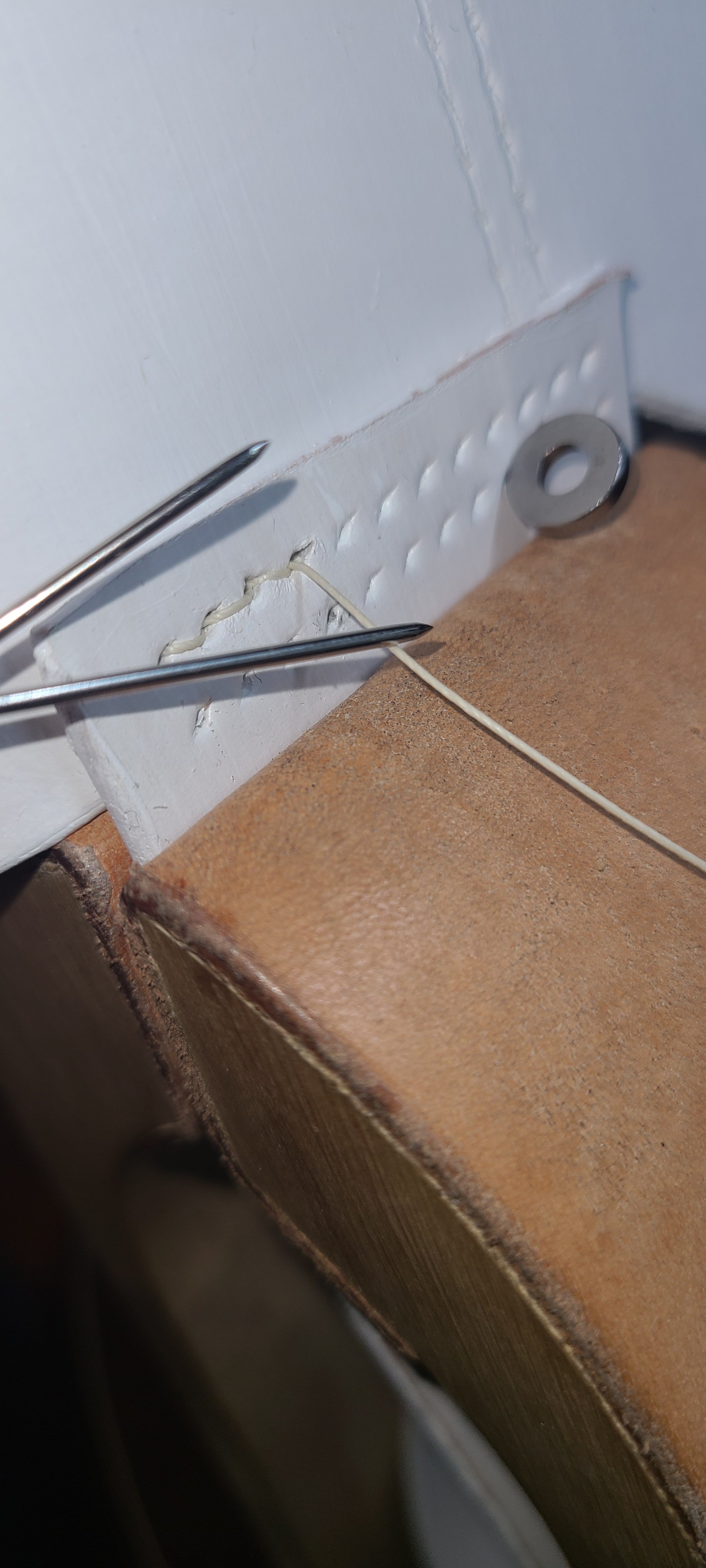
Here is the piece being stitched. It is being held firmly in the stitching pony and the positioning is being fixed by the alignment pin. I am using a basic two needle saddle stitch. The needles are specifically made for leather stitching, They have a blunt tip and a large eye.
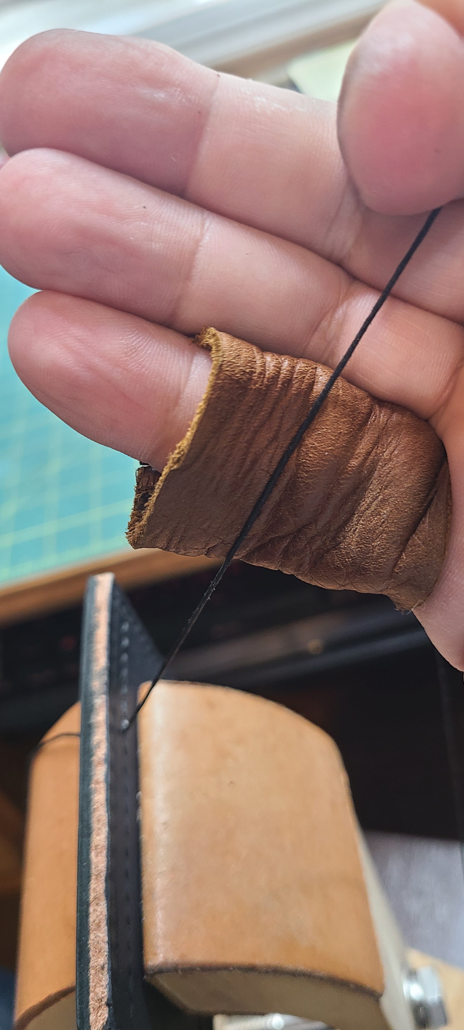
You can see short demo of how the stitching proceeds below. The small overcast that is done before the thread is pull tight insures that the thread lays in the correct orientation in the holes to produce a consistent angle on the top face of the completed product. It is just a more polished, refined look than a simple straight stitch. You can also see in the video that I am wearing a set of leather finger protectors that I made. The thread will tend to cut up your fingers after a long stint of hauling those stitches taut.

Here are the finished leather cross belts

Regards,
Henry
-
Sorry for the delay in posting. As usual life often gets in the way of hobbies.
Since last I posted I have completed all of these leather projects and the end users have taken delivery and are happily wearing them. I did document the rest of the manufacture, and I will continue to add posts here.
I did decide that my existing sergeant sword scabbard and baldric was not in good enough condition to pass along to the new sergeant so I made him a new one. I will include a photo and brief explanation of the manufacture here also.
So, to continue...
I received those alignment pins mentioned earlier. You can see them in the upper right corner of this next photo. The pins are helpful in holding two or more pieces together for alignment, punching, stitching, etc. Here are all the pieces of the cartouche box with all of the holes punched. The box end linings have been glued to the facings with contact cement. They will also be stitched together. You can see the front and back of the end pieces in the photo.
These pieces are now ready to be dyed and edge finished prior to stitching up the box.

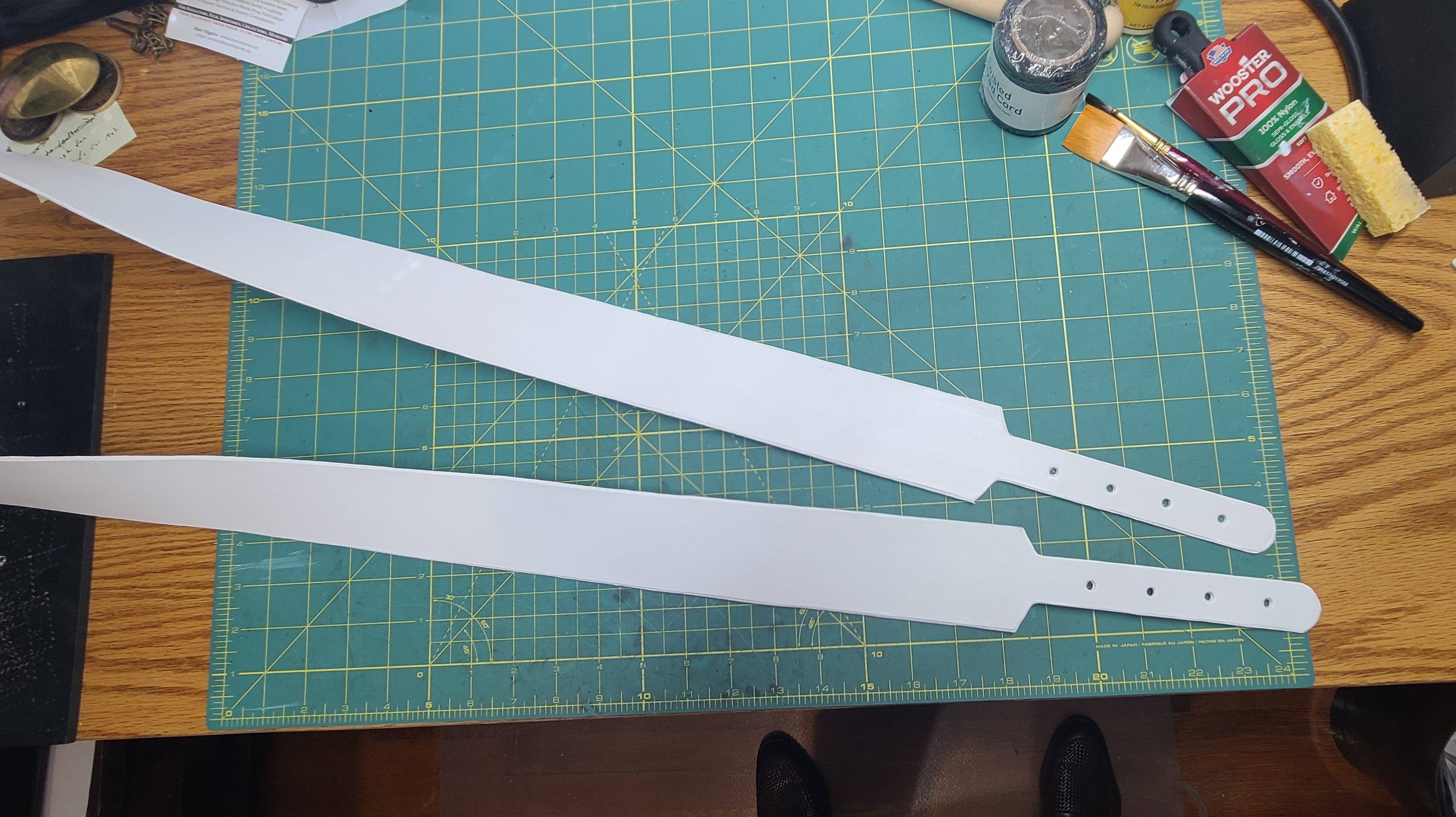
Next we move on to the baldrics, or cross belts. I use the alignment pins to hold the pieces together to determine the fit. As you can see, laying up several pieces of leather makes for a very bulky and hard transition, so the leather must be thinned in a process called skiving. Basically skiving is just shaving off part of the flesh side of the leather to make it thinner. The skiving knife must be kept razor sharp. The blade is not pushed directly through the leather but moved in a slicing motion along an angle like you see in the photo. You work the edge in small bites from one side to the other to thin out the edge. In this case I am beveling the edge to create a less harsh transition between the finished layers of the baldric. There are other variations of the skiving knife employed if you want to thin the entire face of the leather.


Here are the beveled edges and the improved fitment when put together.

Regards,
Henry
- GrandpaPhil, Jack12477 and Canute
-
3
-
-
-
Is this document a French translation? I notice they mis-spelled some other things like 'pendant', and 'collar'. Perhaps they are referring to a Flemish Horse similar to what is used on the end of a yard arm.
Regards,
Henry
-
Anything that needs hauling by hand will most likely stay hemp. Even if other parts of tackle (pendants, etc.) were chain or wire. For example, in clipper rigs, the sheets for the courses were chain from the sail to just through the quarter block, then wire down to the tackle block, and the blocks were rove with hemp.
Regards,
Henry
- wefalck and GrandpaPhil
-
1
-
 1
1
-
There is also the fact that all these lines work as part of a system. Where one line is pulling upwards or outwards, an opposite line is pulling downwards or inwards. You get your tension set up automatically that way. For instance, your boom probably has a sheet line at the end of it that will add a downward pull.
Also, if you can arrange it while prepping for your build. Try adding weight to the parts by incorporating metal inserts or fittings. That might just add enough weight to snug up a line.
Regards,
Henry
- Cast Off and thibaultron
-
2
-
8 hours ago, Sagrado said:
Hello everyone. Give me some advice about the rigging of the boat. I found two different diagrams on the internet. Which one do you think is the most appropriate (HMS Beagle ship)?
a)
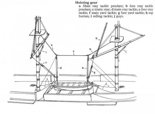
b)
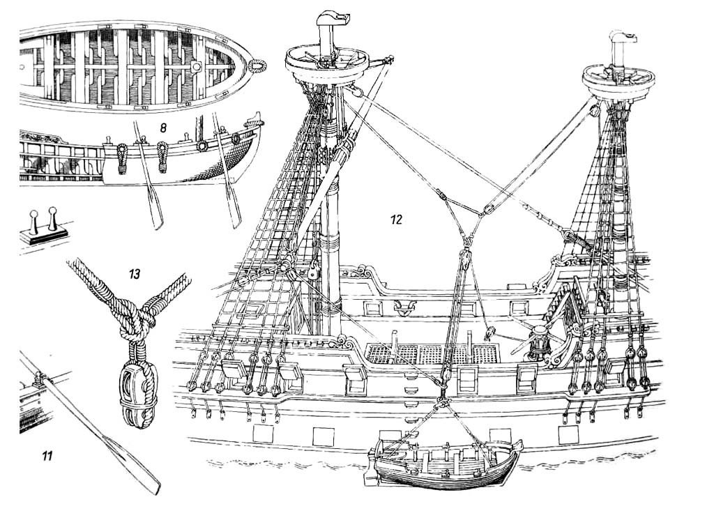
The top figure employs the more modern style of rig (relatively) with the falls suspended from the mast tackle pendants and a triatic stay. The second figure shows the older method of employing a mast pendant and guy assembly (1600's to early 1700's, I believe). (Note the round tops and the tye and halliard arrangement for the yards).
Regards,
Henry
-
A block and tackle system can have blocks with multiple sheaves (pulleys). If there is only one block with a single sheave, then the tackle is called a whip. This type of system provides no additional mechanical advantage (purchase). It is in fact no more than a lead block, which is a block employed to change the direction of the pull, or lead.
If you add another single block to the tackle system, now you have a two part, or two fold purchase. The load is supported by two parts of the rope, therefore the mechanical effort is halved. You can keep adding sheaves to the blocks and "purchase" more force applied to the load. You can have any combination of sheaves for the upper and lower blocks, single, double, triple, or more. One block will usually be fixed in place while the other moves with the load (see figure below).
In the case of your halliard, the lower block is fixed to the deck and the upper block is spliced on to the end of the runner.
Let us assume that you have a tackle arrangement where the hauling (running) end of the rope emerges from the top block. In order to haul that rope you have to be almost beneath the tackle. This limits the number of men that can be employed for the haul. If you add a lead block at the deck level you can change the direction of the pull to horizontal and now you can employ more hands to tail on the rope.

Regards,
Henry
-
Indeed, as is shown in the illustration the runner and halliard come down on opposite sides of the ship. The standing end of the runner (to the left in the picture) commonly had a hook spliced on to the end and was hooked to an eyebolt near the bulwark or rail. The halliard may be in two or more parts with its standing end hooked to an eyebolt opposite the eyebolt for the runner. The lower block of the halliard tackle would be hooked or seized to either another eyebolt close by or the same eyebolt. If the halliard was only a single whip (two part) there would be a leading block at the bottom instead of a tackle block. The hauling part of the halliard would belay to a pin on the rail.
Typically, the halliards for the yards as you go up the masts would switch sides. For instance, the halliard for the topsail yard would come down on the starboard side while the one for the the topgallant yard would come down to port, while the royal would belay to starboard again. The halliards would also switch sides from mast to mast also.
Regards,
Henry
-
I have often wondered about this myself. If you have ever worked with canvas before you know that stowing it means it has to be folded and bundled. But I would not want to be the one that had to handle that bundle. A single topsail could weigh upwards of a ton.
All of the gear (blocks, tackles and the like) would be stored in the boatswains store room.
All of the cables would be coiled on the cable tier in the orlop.
Stowage of sail cloth would be considerably easier because it is only 24 - 26 inches wide and would make a much smaller bundle.
If not lashed in the channels, kedge, stream and spare anchors would be stowed in the orlop.
You can see that the available storage space would be used up very quickly before you even consider shot, food and water.
And, how in the world could you find and get to what you needed efficiently?
Regards,
Henry
-
-
I am waiting on delivery of another item before I dye the backs. There needs to be a little bit of thinning of the leather where some of the pieces come together. I am waiting on some alignment pins before I can get the locations for thinning marked.
In the meantime I have started cutting leather for the cartouche boxes.

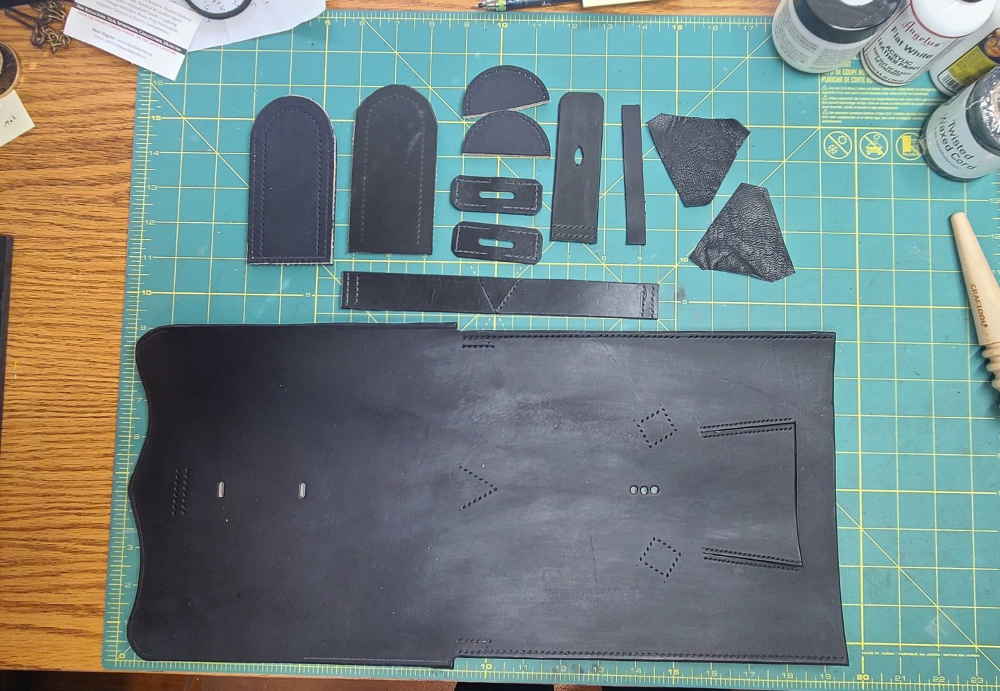
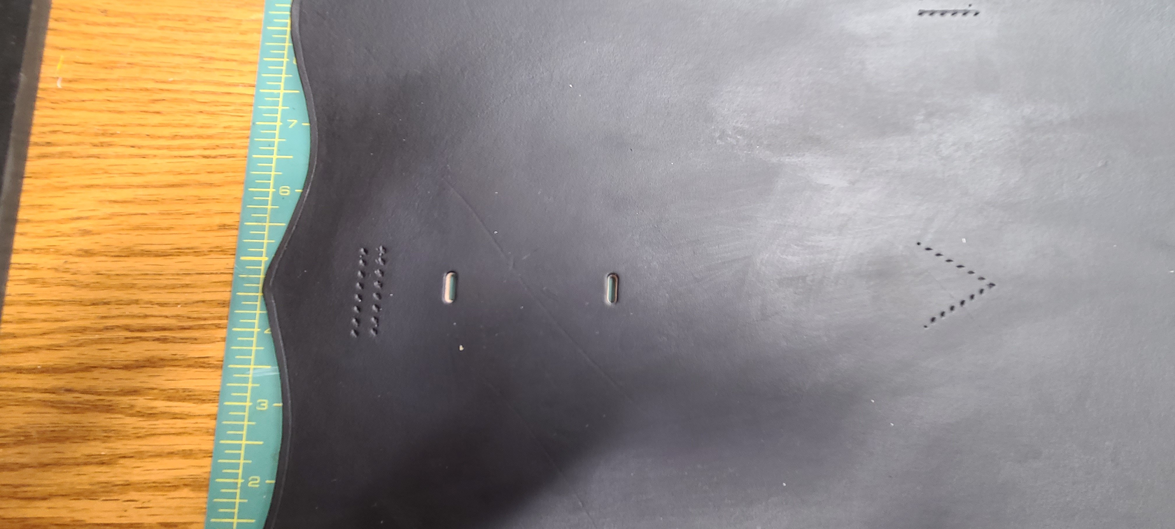
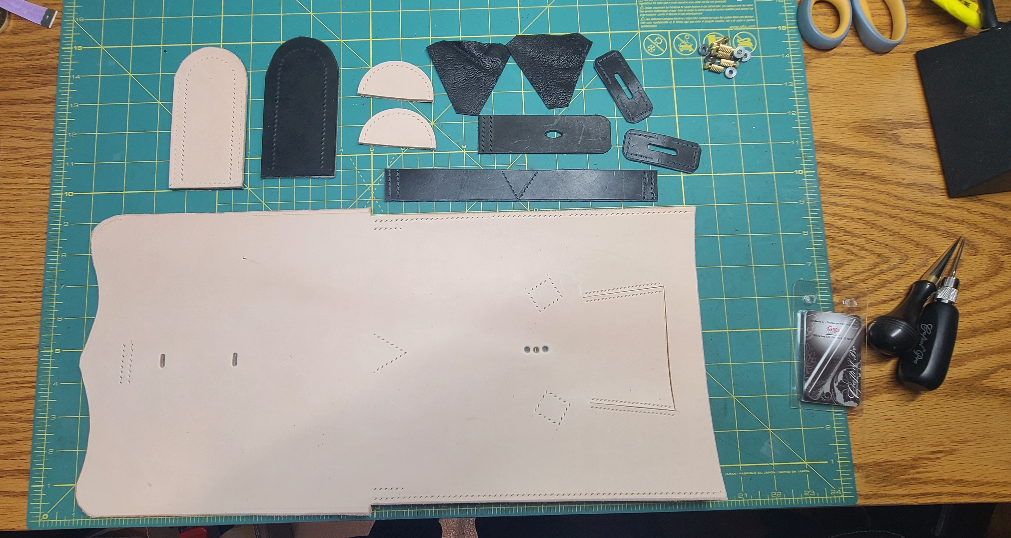
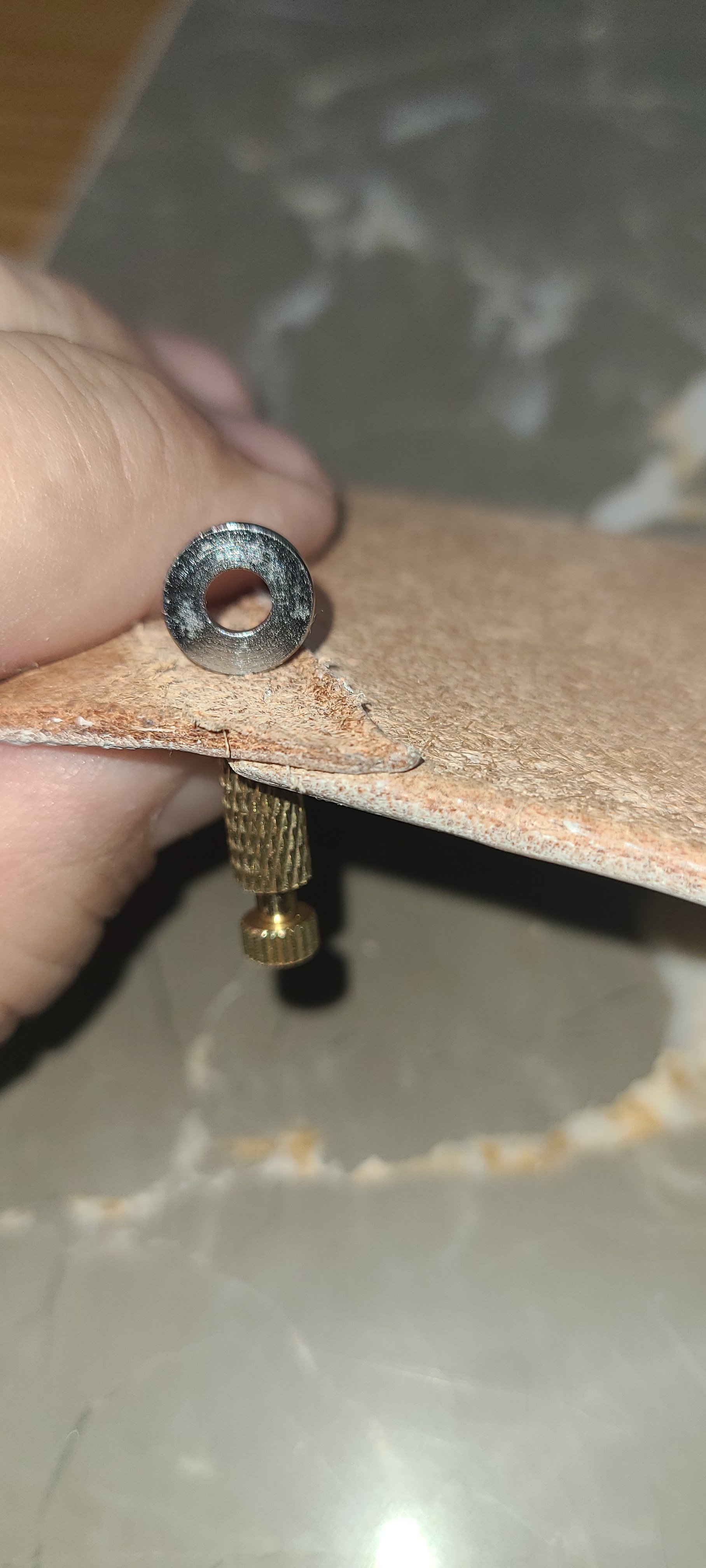
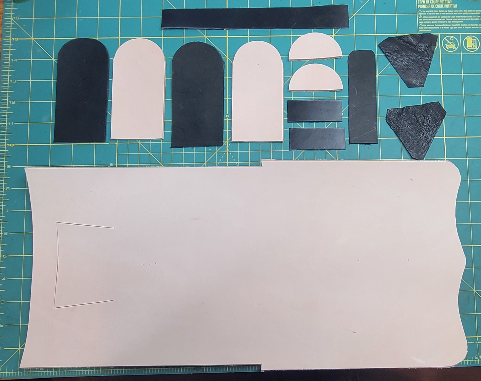
Here are all of the pieces that make up the cartouche box. The body of the box is at bottom. It will be scored and folded to make the front, back, and lid of the box (lid on the right). The box end pieces with their linings are the tombstone shapes. The half circles are the lid ends. Beneath the lid ends are the buckle straps for the cross belt. Next to the right is the closure strap and two gussets for the access panel in the front of the box. Above is the keeper for the cross belts that run across the back of the box.
All pieces will be black. I still need to punch all of the stitching holes. One last piece that I have not figured out how to make yet is a leather knob like object that fastens the box closed.
Stay tuned.
Regards,
Henry
-
More progress on finishing the edges and backs.
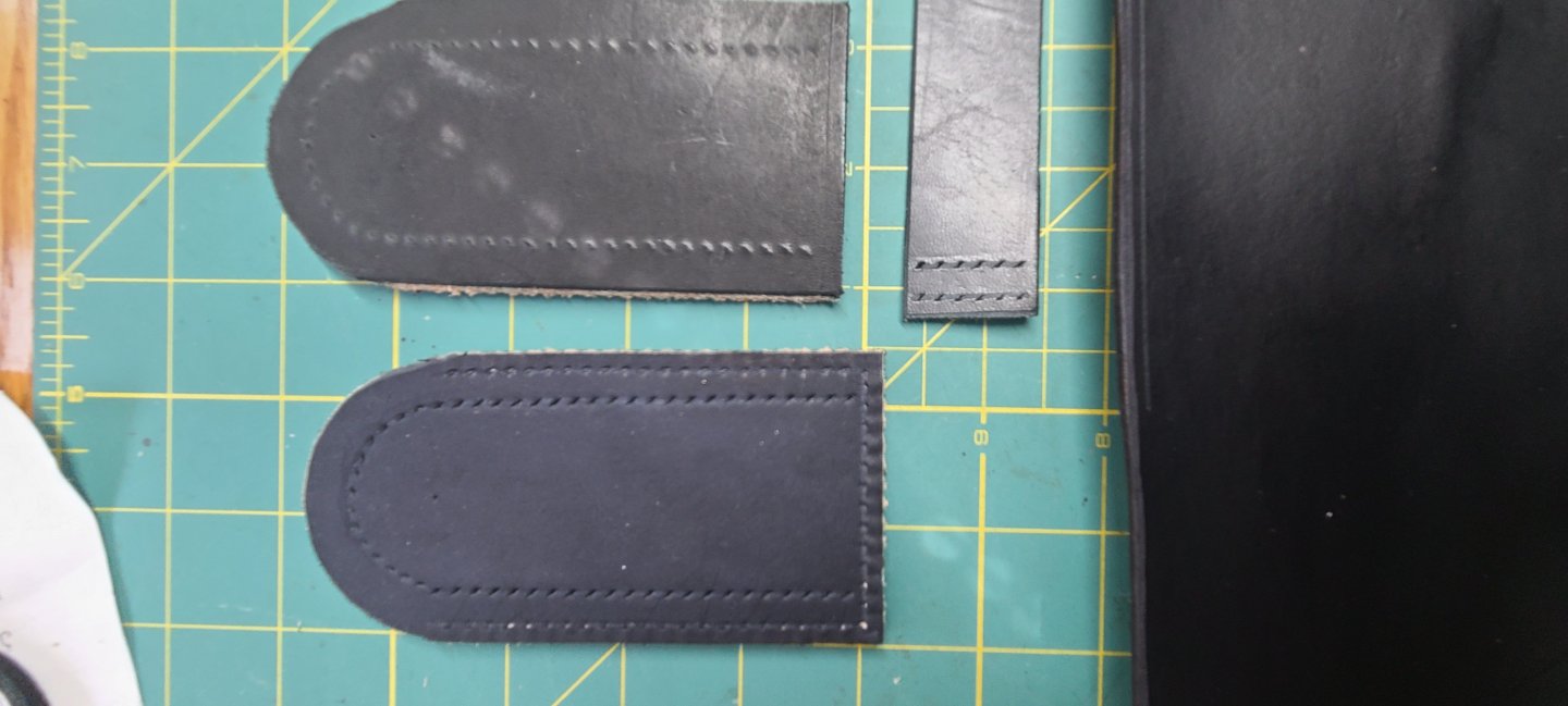
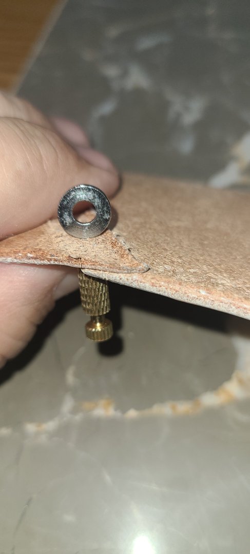
The edges round over and polish up nicely with the burnishing burr mounted on the drill. I am moving on to the backs of the pieces. The nap of the flesh side of the leather needs to be knocked down and polished and a coat of dye applied. I don't need it to be super finely finished because it will be on the inside of all the cross belts when worn. It just needs to be whiter instead of raw leather.
Below are the items used to accomplish this part. Tokonole Burnishing Gum, a thin spreader, and a wood burnishing tool
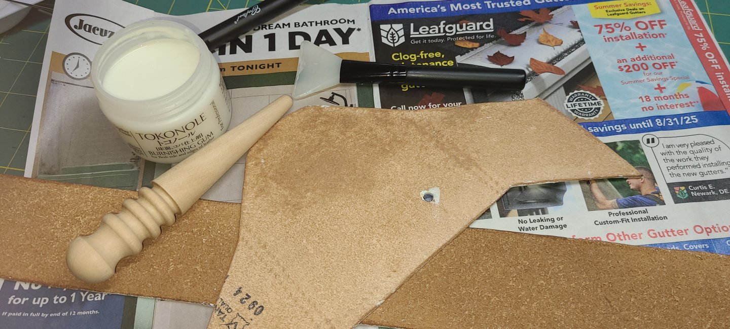
In this second photo, you can better see how much the nap is knocked down. The piece on top is finished ready for white dye.

Next step is dying the backs white followed by white edge coat, and the pieces will be almost ready for assembly.
Regards,
Henry
- GrandpaPhil, Canute, Jack12477 and 1 other
-
4


Revell 1/220 scale Cutty Sark assembly questions
in Plastic model kits
Posted
Going by other Revell kits that I had, usually the A, B, and C variations are a choice you make before starting the rigging to determine if you want to show the vessel A - without sails, B - with plain sails (that is the square sails and the triangular jibs and staysails), or C - with full sails which will include all of the plain sails plus the studding sails.
May I suggest you start a build log and we can follow along and help you out on your rigging journey.
Regards,
Henry