
.JPG.ca33079f5815b861e67b9c2cccd37982.JPG)

Blue Ensign
-
Posts
4,520 -
Joined
-
Last visited
Reputation Activity
-

 Blue Ensign reacted to jwvolz in HMS Sophie from Cruizer kit by jwvolz (Joe V.) - FINISHED - Caldercraft - 1:64 - kitbash
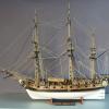
I've completed the hatches and have used the Gannet deck layout to position them.
The companionway and capstan are also complete, but I'm likely going to leave them off until cannon rigging/installation is complete.
I'm going to base the head off of the sister ship drawing of Epervier in Chapelle's History of the American Sailing Navy. The kit plans and parts are not even close to correct in this area.
Work has begun on the cheeks. These pieces are made from Boxwood.
-
Blue Ensign reacted to jwvolz in HMS Sophie from Cruizer kit by jwvolz (Joe V.) - FINISHED - Caldercraft - 1:64 - kitbash
The deck has been laid. I used maple from Crown Timberyard, with a boxwood waterway. . I like the subtle variations and look of the maple, and had used it previously on Granado. I rough counted the treenails at somewhere over 1800 holes...They were done with the drill and fill method. This filler ended up having a bit more contrast than I wanted after staining, but the deck furniture and armament will hide a good bit of the "busy-ness".
I also hung the rudder.
On to the deck furniture.
-
Blue Ensign reacted to jwvolz in HMS Sophie from Cruizer kit by jwvolz (Joe V.) - FINISHED - Caldercraft - 1:64 - kitbash
I've gotten some details such as cap rail, fenders and side steps installed and painted the remainder of the hull. Starting to look like a ship...
-
Blue Ensign reacted to jwvolz in HMS Sophie from Cruizer kit by jwvolz (Joe V.) - FINISHED - Caldercraft - 1:64 - kitbash
Thanks guys.
Not a big update, but I've weathered the copper plating. I used the "bodily fluid" method mentioned elsewhere on the site, and it worked out quite well. It took a few applications to even out due to some initial beading up that occurred.
I have used the salt/water/vinegar method in the past on Model Expo tape, and tried it initially this time, but it didn't work properly. I think there is some type of coating on the copper, which is difficult to remove.
I sealed the copper with Testor's Dullcote lacquer, applied with my airbrush.
I am a bit further ahead than this, but need to catch up on photos.
-
Blue Ensign reacted to jwvolz in HMS Sophie from Cruizer kit by jwvolz (Joe V.) - FINISHED - Caldercraft - 1:64 - kitbash
I've spent the last couple weeks working on the coppering. Since the Cruizer kit does not come with copper plates I used Model Expo's copper tape.
To simulate the nails I made a jig (several actually, depending upon pattern) and stamped individual plates. A few years back, a member of our model club had given out a large supply of hypodermic tubing in various sizes. I had used it for gun barrels on plastic aircraft but thought in this case it would make the perfect nail simulator. The tubing was cut with a dremel and cut-off wheel and CA'd into a piece of boxwood which had the pattern drilled into it. This was backed with another piece of boxwood and a solid rap with a hammer produced a nice plate. I think the hollow tubing does a great job simulating an actual nail dimple.
Copper is hard to photograph...
-
 Blue Ensign got a reaction from RonaldB in Revenge by Emelbe - Amati/Victory Models - 1/64 scale
From the work you've done so far Martin, I think most of us, and certainly me, would be well satisfied with the standard of your build, and like you I was attracted to this kit when I first saw it - maybe when Pegasus is finished..........
I will continue to follow your build with great interest.
Regards,
B.E.
-
 Blue Ensign got a reaction from Piet in Licorne 1755 by mtaylor - 3/16" scale - French Frigate - from Hahn plans - Version 2.0 - TERMINATED
She's looking impressive Mark, you must surely be pleased with your efforts.
I like the effect you have achieved with the stern lights, and that is a neat job on the rudder coat.
B.E.
-
 Blue Ensign got a reaction from Ferit in Frigate Berlin by Ferit KUTLU - Corel - 1/40 - 1674
Good to see you back Ferit, looking forward to your renewed progress.
B.E.
-
 Blue Ensign got a reaction from popeye the sailor in HMS Diana by realworkingsailor (Andy) - Caldercraft - 1:64
She's looking a class job Andy, well done
B. E.
-
 Blue Ensign got a reaction from Canute in Licorne 1755 by mtaylor - 3/16" scale - French Frigate - from Hahn plans - Version 2.0 - TERMINATED
She's looking impressive Mark, you must surely be pleased with your efforts.
I like the effect you have achieved with the stern lights, and that is a neat job on the rudder coat.
B.E.
-
 Blue Ensign got a reaction from FriedClams in Licorne 1755 by mtaylor - 3/16" scale - French Frigate - from Hahn plans - Version 2.0 - TERMINATED
She's looking impressive Mark, you must surely be pleased with your efforts.
I like the effect you have achieved with the stern lights, and that is a neat job on the rudder coat.
B.E.
-
 Blue Ensign got a reaction from CaptainSteve in Licorne 1755 by mtaylor - 3/16" scale - French Frigate - from Hahn plans - Version 2.0 - TERMINATED
She's looking impressive Mark, you must surely be pleased with your efforts.
I like the effect you have achieved with the stern lights, and that is a neat job on the rudder coat.
B.E.
-
 Blue Ensign got a reaction from mtaylor in Licorne 1755 by mtaylor - 3/16" scale - French Frigate - from Hahn plans - Version 2.0 - TERMINATED
She's looking impressive Mark, you must surely be pleased with your efforts.
I like the effect you have achieved with the stern lights, and that is a neat job on the rudder coat.
B.E.
-
 Blue Ensign got a reaction from EJ_L in Licorne 1755 by mtaylor - 3/16" scale - French Frigate - from Hahn plans - Version 2.0 - TERMINATED
She's looking impressive Mark, you must surely be pleased with your efforts.
I like the effect you have achieved with the stern lights, and that is a neat job on the rudder coat.
B.E.
-
 Blue Ensign got a reaction from Omega1234 in Licorne 1755 by mtaylor - 3/16" scale - French Frigate - from Hahn plans - Version 2.0 - TERMINATED
She's looking impressive Mark, you must surely be pleased with your efforts.
I like the effect you have achieved with the stern lights, and that is a neat job on the rudder coat.
B.E.
-
Blue Ensign reacted to mtaylor in Licorne 1755 by mtaylor - 3/16" scale - French Frigate - from Hahn plans - Version 2.0 - TERMINATED
Thanks for the comments, the "likes" and just looking in...
At last, a real update as life (the Admiral's health) got in the way. The frame extensions have been removed and she's starting to look more like a frigate. I still need to sand them down to the sheer strake but I'll be doing that when I need a break from the gundeck work.
Here's the pictures... as always, a click on them will open them to full size (or what constitutes full size on MSW). The last two are more of a reference shot for examining things on my part but I thought I'd toss them in anyway. Sorry about the sawdust and mess.....
-

 Blue Ensign got a reaction from FrankWouts in Le Superbe by Blue Ensign - FINISHED - Heller - PLASTIC - Built as "Le Praetorian", after Boudriot
Detail shots of the completed model
Long boat with the sheep pens beneath.
Activity on the Qtr deck, the crew are converted ‘N’ scale rail figures.
Poop deck detail.
Crew ascending the Main shrouds.
Fore deck detail.
Crew at the Fore Topmast head.
Head details.
Stern Qtr details.
Full shots of the model
Secure in her protective case.
I think this has been the most exacting build I have undertaken due to the small scale and my
less than good eyesight, I am very pleased with the result but I don’t think I
will attempt another at this scale.
I am much more comfortable with 1:64 scale, as with my current Pegasus build.
B.E.
-
 Blue Ensign got a reaction from PeteB in Le Superbe by Blue Ensign - FINISHED - Heller - PLASTIC - Built as "Le Praetorian", after Boudriot
Continuing:
Raising the Topsail yards.
A word about yards.
Working out the details.
Parrals at 1:150 scale are pretty small.
Topsail yard in place,
A member of the Royal Corps of Marine Infantry gives scale to the top.
The sails were attached, dampened and pulled into position using the Buntlines, Leechlines, and clues.
Rigging the anchors.
-
Blue Ensign got a reaction from FrankWouts in Le Superbe by Blue Ensign - FINISHED - Heller - PLASTIC - Built as "Le Praetorian", after Boudriot
Continuing:
Details of the sails.
These were drawn from the plans of Boudriot and are made of Modelspan
tissue .
Attaching reef points nearly destroyed what little was left of my sanity.
As did the ratlines using 125g copper wire.
Almost done.
-
 Blue Ensign got a reaction from daHeld in Le Superbe by Blue Ensign - FINISHED - Heller - PLASTIC - Built as "Le Praetorian", after Boudriot
Continuing
Waist with Longboat and sheep pens.
Quarterdeck modifications with added cabin detail.
Modified berthing of the Main Ladderway and added Chicken Coops on the Poop deck.
Modified Head.
Copper wire and strip used to make the chains and preventer plates.
Upgrading the Long boat.
Modified ‘N’ scale figures fit just right.
The finished boat.
Rigging the ‘show’ guns was a bit of a challenge at this scale
Rigging can get a tad untidy at this scale, blocking yourself out is so easy.
-
 Blue Ensign got a reaction from Bill Morrison in Le Superbe by Blue Ensign - FINISHED - Heller - PLASTIC - Built as "Le Praetorian", after Boudriot
From Le Superbe to Le Praetorian – A Heller Seventy-four, after Boudriot
This is a summarised record of my attempt to modify a small scale plastic
kit by reference to the works of Jean Boudriot. Very few of the original kit
fittings were used in the build.
This was to be a first attempt at fully detailing a model of this scale,
adding sails and displaying in a waterline setting.
Early progress
Lower deck detail.
Upperdeck showing Galley and Pastry oven.
One unfortunate fellow is spending time in the bilboes, for swearing on a Sunday.
Restyling the Foc’sle rail.
Modified waist railings using brass strip.
-
Blue Ensign got a reaction from Piet in HMS Diana by realworkingsailor (Andy) - Caldercraft - 1:64
She's looking a class job Andy, well done
B. E.
-
 Blue Ensign got a reaction from mort stoll in HMS Diana by realworkingsailor (Andy) - Caldercraft - 1:64
She's looking a class job Andy, well done
B. E.
-
 Blue Ensign got a reaction from realworkingsailor in HMS Diana by realworkingsailor (Andy) - Caldercraft - 1:64
She's looking a class job Andy, well done
B. E.
-
Blue Ensign got a reaction from mtaylor in Frigate Berlin by Ferit KUTLU - Corel - 1/40 - 1674
Good to see you back Ferit, looking forward to your renewed progress.
B.E.