HOLIDAY DONATION DRIVE - SUPPORT MSW - DO YOUR PART TO KEEP THIS GREAT FORUM GOING! (78 donations so far out of 49,000 members - C'mon guys!)
×


dcicero
-
Posts
267 -
Joined
-
Last visited
Content Type
Profiles
Forums
Gallery
Events
Everything posted by dcicero
-
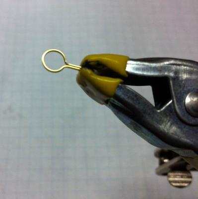
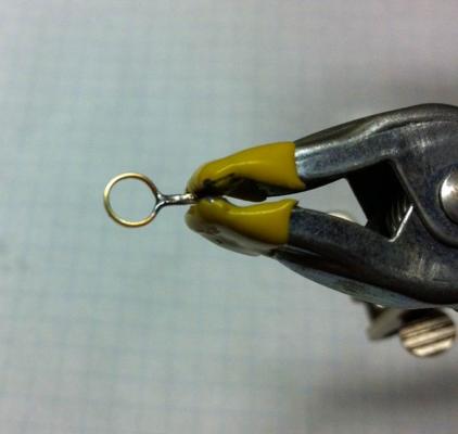
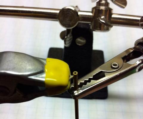
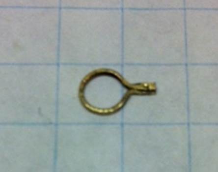
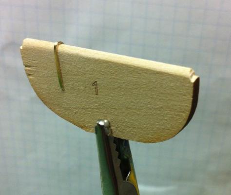
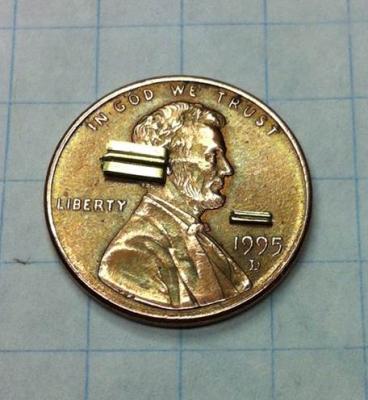
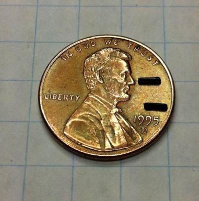
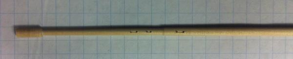
Thanks for all the kind words, everyone! I started on the mast bands today and ran into some trouble. Now I'm looking for advice. It all started promisingly enough... I located the right spot on the mast for the band. Then I bent the brass strip around the mast, crimping it. Then I removed the band from the mast. Looks good so far. Holding the band together with a clamp... I soldered it together. Then I dressed it with a sanding stick, getting rid of the excess solder. That's when the trouble started. I couldn't for the life of me, drill that little hole. I used dental drills -- thanks, Marc! -- and small diameter drills that I'd used on other things. I put them in my Dremel after my pin vice failed to do the job. Nothing worked. I just couldn't cut through the brass and solder. Then I thought, why don't I make a fitting that will do the same job. I cut the end off the band and got a little brass tubing I had, figuring I'd just solder it on the end. That worked alright, but trimming the brass tubing was problematic. (It took too much pressure to cut the tubing and the solder joint failed.) So, back to the drawing board. I figured that, if I made another band like the first, but twisted the end 90°, I could make a flat enough area to drill the hole and maybe use less solder, if that was the problem. I did that and the results were fine. But I still couldn't drill that hole. What might I try? Dan

-
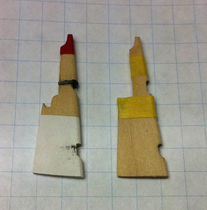
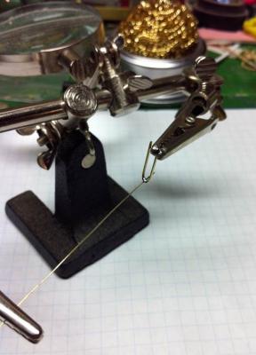
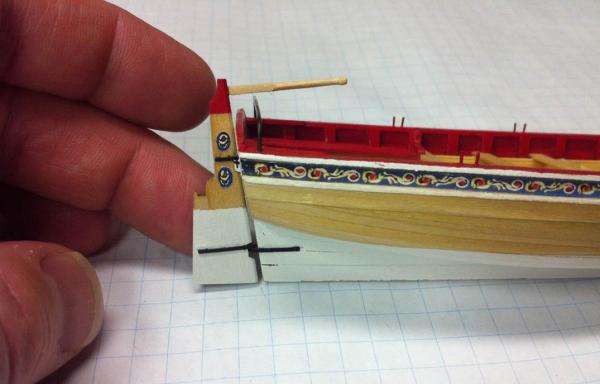
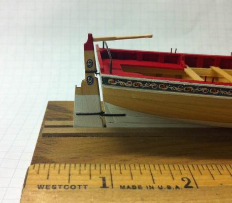
It's been a month since I posted anything, but it's been an eventful month. The rudder has been giving me fits, but I finally finished it off. Sanding the rudder to its final shape is straightforward. Nothing much to that. Once that was done, I decided to paint it. Had a little trouble with that because the paint bled under the tape. Tried to fix that. The fix didn't work very well. Continued anyway... I needed to make the pintels and gudgeons. I started by bending the brass strip over a piece of scrap wood the same thickness as the rudder. Better to mess this up, I thought, than the actual rudder. Then I tried to glue the 28 gauge wire into the bent piece of brass to finish the pintel. I tried CA glue. No go. The thing just fell right out. No problem, I thought. I'll solder it in. I found my 1983 vintage 20W soldering iron -- the one with the completely corroded tip -- my old Radio Shack resin-core solder and went at it. The result: disaster. Big glob of solder and a cold solder joint. Kurt Van Dahm set me straight. I needed to upgrade my soldering rig. I bought a new soldering iron from Radio Shack. (Probably should have ordered a Weller from Amazon, but I didn't want to wait for it.) I got some acid flux and 50/50 Lead/Tin solder from Ace Hardware. That's what's needed for soldering brass. I used my Helping Hands as a jig to hold the wire and the piece of brass strip. The results were great. I blackened the pintels using Birchwood Casey Brass Black. I really like the finish you get with the Birchwood Casey, but I've found getting a really tenacious finish takes a lot of iterations. And even when I go through that effort, if I have to work with the piece much, it does seem to rub off. That's what happened with the pintels. I didn't get them exactly in the right place the first time, so some of the finish rubbed off on the rudder itself. By now, the rudder was starting to look really rough: bad paint, stains from the pintels. It was junk. I made another one, figuring I could learn from my mistakes. The second time around, I was much more careful about masking the paint job. And I made sure not to leave behind any residue from the Birchwood Casey. I also touched the brass up with paint, which won't rub off. The results, I thought, were really good. I applied the first coat of Watco's Danish Wood Oil. No problems. I applied the friezes using white glue. Simple enough. I carved the tiller from a piece of 1/16" x 1/16" stock. That took a while, but turned out pretty well. To attach the tiller to the rudder, I drilled a small hole in the end of the tiller and, using CA glue, stuck a piece of wire in the end. Then I drilled a small hole in the tiller head and, again with the CA glue, tacked the tiller into place. Installing the eyebolt in the transom was, again, simple enough. The lower gudgeon was a little trickier because 1) it has a compound curve that you need to bend into place and 2) it has to line up with the pintel on the rudder in a straight line. I actually thought that alignment was going to be harder than it was, but it went into place the first time. This is a small piece, but there's a lot involved in it: ten pieces and ten different materials (basswood, brass strip, brass wire, paper, white glue, CA glue, solder, paint, Birchwood Casey, Watco's) ... oh, and a month's work. Dan
- 175 replies
-
- 8
-

-
- 18th century longboat
- model shipways
- (and 1 more)
-
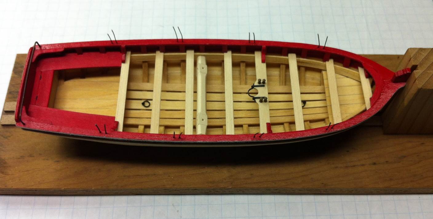
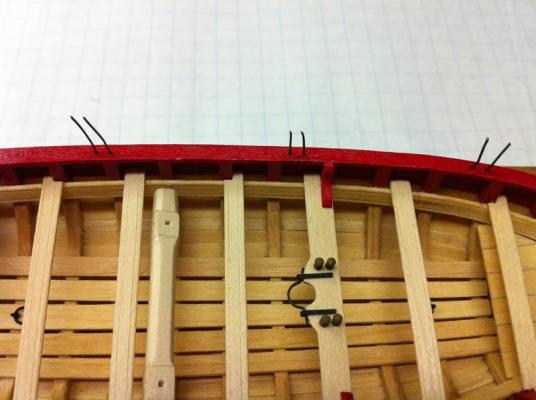
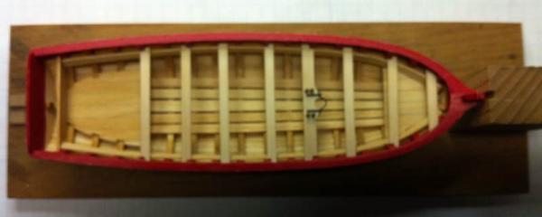
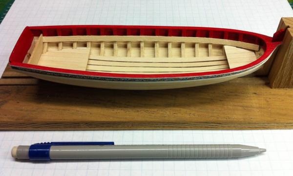
I've got the oarlocks installed. I made a little jig to consistently space and trim them. Looking at the plans, they're 3/32" tall, so I glued three pieces of 1/32" stock together. Then I drilled some holes in it at the correct spacing, per the plans. Then I pushed some pins through the whole thing. This allowed me to maintain the proper spacing between the two pieces of the oarlocks and line them up athwartships so they'll be symetrical. I just pushed the pins lightly into the cap rail where I wanted the holes and then drilled them out to accept the wire used for the oarlocks. There's not much thickness to that caprail, so a light touch is needed. Otherwise, you'll go right through it! (Trust me, I know...) Once that was done, I just glued -- with a little CA -- lengths of wire into the holes. Once they were in, I removed the pins and slipped the jig over the long wires. That did a few things for me. First, it allowed me to trim them all off to the same length. Second, when you snip the wires, they look like they've been snipped off! They don't have a nice, round cross section like a real oarlock would. They're fragile, though, so you can't just file them without breaking them off. With the jig, you can. Snip them to the right length and then use a file to file them down to the final length and finish. That's all for that little part of the project. One other thing... When I finished trimming all the oarlocks down, they looked longer than they should have been. Sure enough, when I measured them, they were closer to 4/32" than 3/32". Turns out, the sheer of the caprail raised my little jig just a tiny amount, so, even though the jig is the right thickness, it produced an oarlock slightly longer than I wanted. I knocked one of the layers off the jig and went back through all the oarlocks and trimmed them again. After that, they were all 3/32" long, even using a 2/32" thick jig. Go figure. Dan
- 175 replies
-
- 5
-
-
- 18th century longboat
- model shipways
- (and 1 more)
-
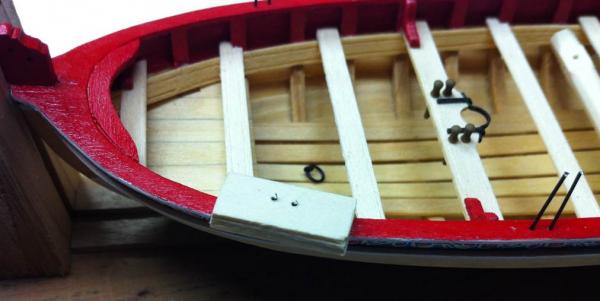
I've been pretty busy lately, so not a lot of progress has been made on my longboat. Got some stuff done over the weekend, though, so I figured it was time for an update. A couple of weeks ago, I brought the model up to Manitowoc, WI for the 38th Annual Model Ships and Boats Show and Contest at the Wisconsin Maritime Museum. What a great event in a great location! Obviously, the longboat was there just for display this year. Next year, it'll be in the contest. Back in the workshop and motivated by all the great models I saw in Manitowoc, I started installing the knees around the boat. There really isn't much to this. They go in pretty easily for the most part. The two knees in the bow and the part that fits around the bow itself were a little trickier. I got the knees in last night (and didn't take a picture) and the bow piece is going to take a little surgery. The part in the kit needed to be sanded down quite a lot to fit the bow, to the point where it really didn't look correct. I'll take a swing at making a new part and fitting it in. Next came the windlass. I was a little apprehensive about this part. Bob Filipowski made a presentation at our last NRMSS meeting about how he made his windlass. Looked like a tricky operation. Here's how I did it. The first thing I needed to figure out was how to make those eight sides all parallel to the centerline of the windlass. I cut the square stock and marked the locations of the various sections of the windlass. I plunked the square stock on my building board. That held it securely in place and gave me a reference to the centerline of the windlass. Then I carefully sanded, using a sanding stick, parallel to the building board. It only took, maybe, four passes with the sanding stick to finish off one of the sides. As the instructions say, I scored the lines between the sections to make them stand out more. And I made the square holes almost the same way Chuck did. The difference? The business end of my square file is square, but the other end is round. I had to use the business end, which worked out fine. (Getting the sawdust out of those little holes was a little tricky!) Then I drilled holes in the end of the windlass and put short pieces of wire in them. Here they are, prior to trimming. I wish I'd taken a picture of the end of the windlass. You can clearly see eight sides, all nice and symmetrical. And so here it is, installed. Chuck mentions that the wire axles on the end of the windlass need to be short. He's right about that. I ended up trimming them down to almost nothing to get them to fit into the small holes in the risers. Once installed, though, the thing rotates just as it should! I didn't take pictures of them yesterday, but I also installed the two lifting rings in the bottom of the boat. They look good and add a nice level of detail to this model. More pictures of that stuff to follow. Dan
- 175 replies
-
- 10
-
-
- 18th century longboat
- model shipways
- (and 1 more)
-
Regarding edge bending, I tried all kinds of techniques before finding one that worked for me. I tried thoroughly wetting the planks, wrapping them in paper towels and nuking them in the microwave for 2 minutes. That works. It produces a nice al dente plank! Seriously, it's like working with a noodle. You need to shape the plank prior to cooking it, though. You can't sand those noodles... I tried the "long soak" method, where you leave the plank in the water for a long time, letting it get thoroughly waterlogged. (I used a tray used for mixing up drywall mud for that.) Less work than cooking the planks in the microwave and about the same result. Here's the one that worked for me. Cut the plank to a length slightly longer than you need. Go to the sink and get it wet. Don't waste a lot of time. Just run it under the water and get it wet. Then clamp it to a piece of plate glass. I got mine at a glass shop for just a couple of bucks. Mines 12" x 12" and a little bigger than necessary. I think 6" x 12" or even 6" x 6" would be fine. Use lots of clamps and get the best bend you can in it without it buckling. Come back in 10 minutes or however long it takes for the plank to dry. Take off the clamps and you'll see the plank try to snap back to its original shape, but not all the way back. Wet it again and clamp it again. You'll find, the second time, that it'll bend a little farther. Let it dry. I found that two or three iterations were needed to get the more extreme bends in the plank. Here's the part that I missed initially and had to learn over time. Just because you're edge bending doesn't mean you don't have to spile the planks. They're still going to need to be bent a little -- in the normal way, not more edge bending -- carved a little, sanded (to the get the edges to mate properly) and generally finessed into place. It gets a lot easier after you've gotten the first two or three planks in place, but I found fiddling with the planks is still necessary, even with the edge bending. Dan
- 132 replies
-
- 2
-
-
- 18th century longboat
- model shipways
- (and 1 more)
-
Looks like a fun project, David. You seem to have caught the card modeling bug! Dan
-
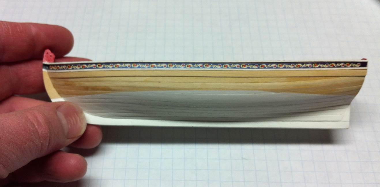
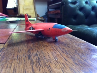
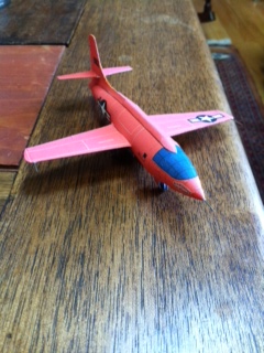
David: Your work inspired me to look at some of the old paper models I have. Luisa had some health problems recently and I just didn't have the mental energy to work on the Longboat. Paper modeling was just the thing. I printed out this model of the Bell Aircraft X-1, aka Glamorous Glennis. This was the aircraft in which Chuck Yeager broke the sound barrier back in 1947. Took just a few modeling sessions, maybe four in all. It turned out alright, although I need to do a better job touching up the seams. Tried the colored pencil route, but the kids just didn't have exactly the right shade of orange! Hope you're feeling better. We all missed you in Manitowoc. Dan
- 27 replies
-
- 1
-
-
- teazer
- blockade runner
- (and 2 more)
-
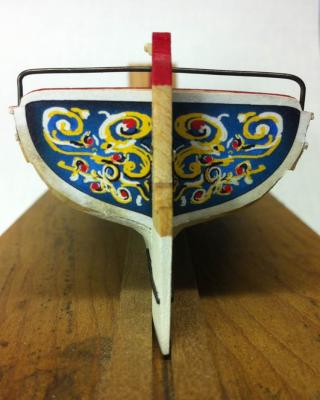
The flags look great, Marc. I think if you hit them with a little Dulcoat, they'll lose that "too bright" look. Sometimes, I think people project a modern sensibility on prior centuries. This happens all the time with views of the American Civil War. Millions of photos exist from the Civil War ... all in black-and-white, giving the impression that things were not very colorful back then. In fact, the opposite was true. They loved colorful things back then as much as we do now and sailors painted their ships to impress! Bright colors were used, but on a model they need to be toned down a little to make them look properly to scale and not like toys. Dan
- 85 replies
-
- 2
-
-
- yacht mary
- mamoli
- (and 1 more)
-
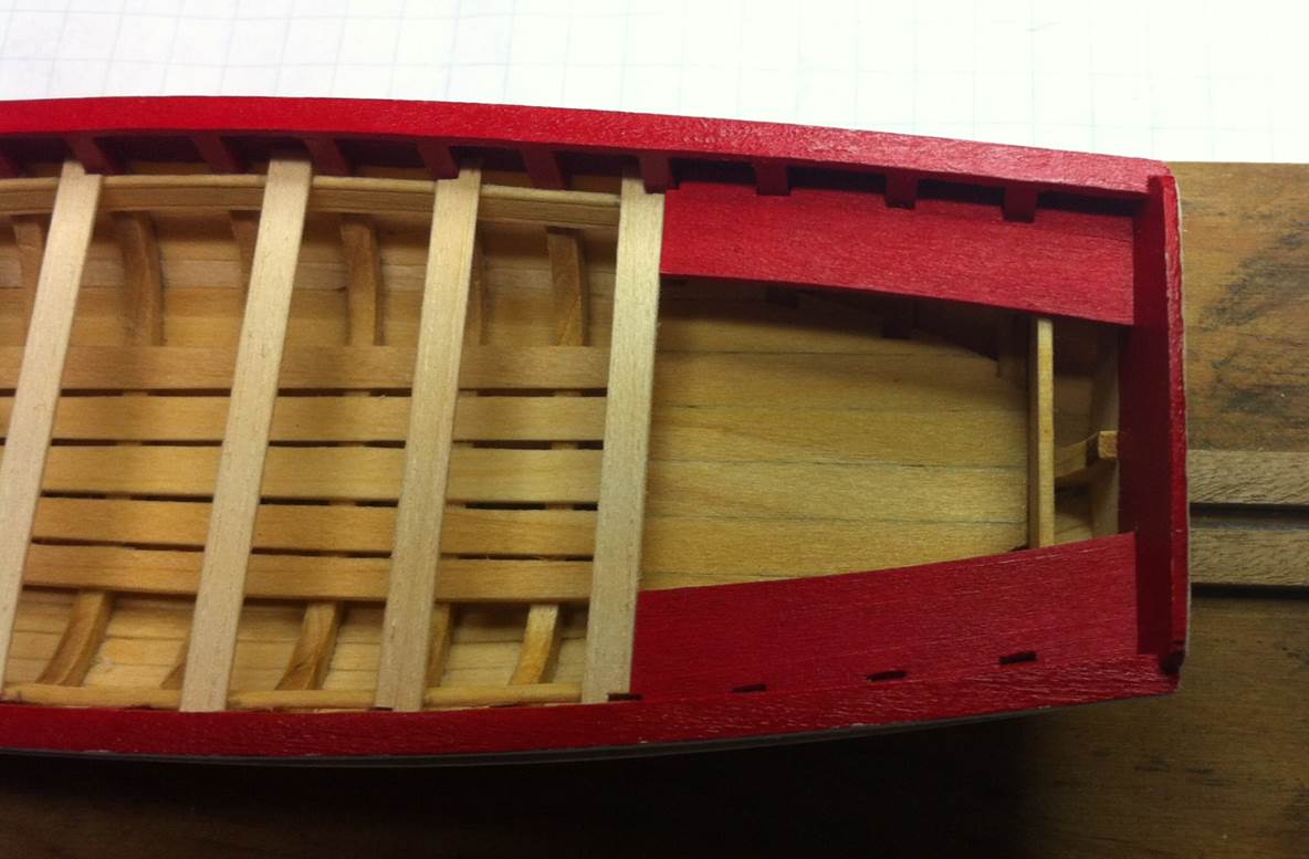
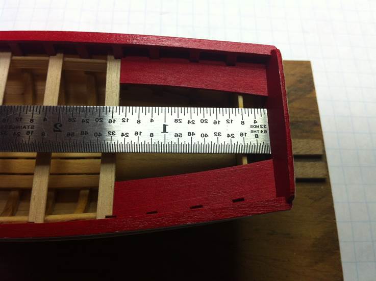
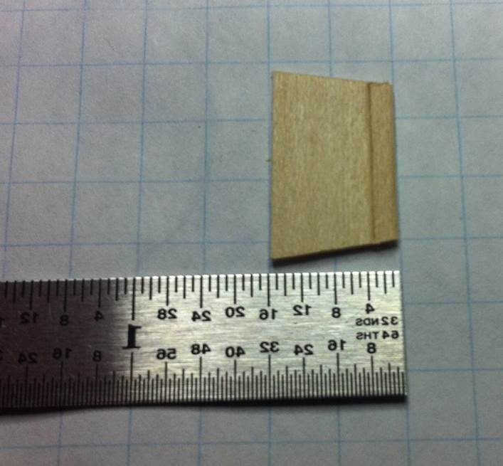
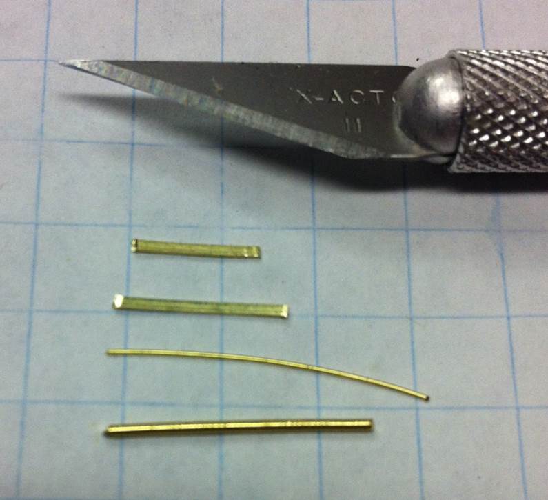
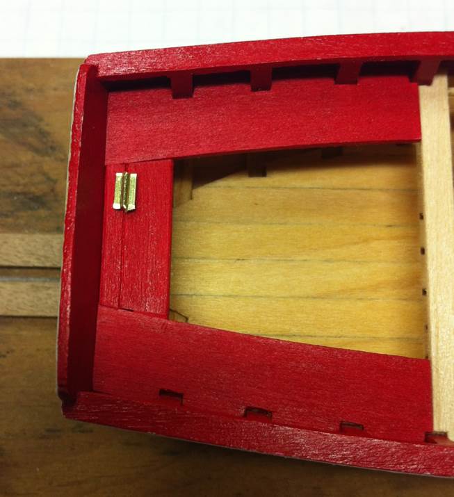
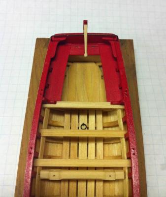
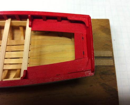
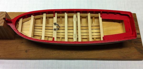
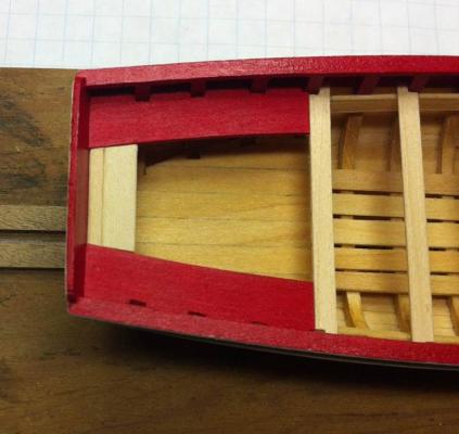
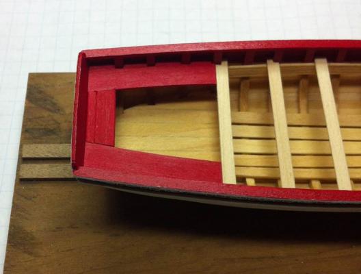
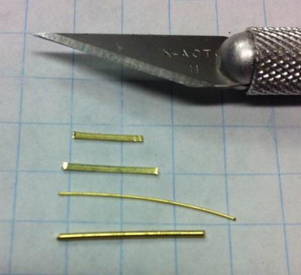
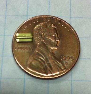
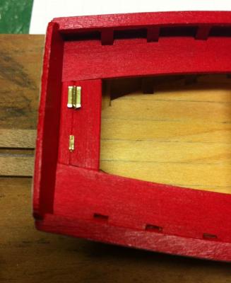
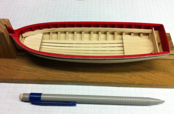
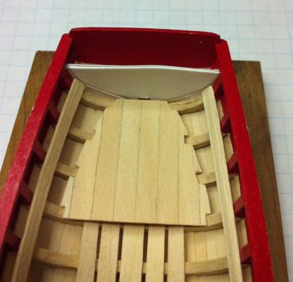
Not a tremendous amount of progress to report, but some... I've got the seats and the locker lid installed. This whole operation was pretty straightforward. I fitted the seats in place by cutting the notches needed to fit around the frames. Then installed them. There was one tricky part of this process. The seat, locker lid and the thin part of the locker lid that butts up against the transom: four pieces. There isn't much gluing surface to work on the locker lid, so dry fitting all four pieces gave me a little trouble. I installed the seats first because, once in place, I would be able to concentrate on the locker lid. The cut piece in the kit is substantially bigger than it needs to be. As can be seen here, the distance from the transom to the end of the locker is only about 8/32". And the locker lid -- with the stern piece attached -- is about twice that wide. So cutting that piece down to size and maintaining the proper angle on the edges is a little tricky. Once in, I just painted it. Then an interesting part of the project came up. I was trying to figure out how to make the hinges described in the instructions. Seemed pretty simple: use the narrow brass strip and some 28 gauge wire and, well, just make them. But I thought that 28 gauge wire was a little narrow and the brass strip was tiny too. Wouldn't it look too small? I figured I could make some pretty convincing hinges, so I started. Here are all the materials. I started by cutting two little pieces of brass strip and putting a small piece of 20 gauge wire between them. I glued them together with CA and then cut out the assembly to make the hinge. I thought it looked good. This is a really small hinge. But when I put it on the boat, it looked huge an out-of-scale. So I made some smaller hinges. That process was simpler. I just used the CA glue to attach a piece of 28 gauge wire to the narrow brass strip. I made two of those. Those small hinges look a lot closer to scale. Now we're talking about some really, really small hinges. I had to paint them flat black because putting them in the brass black with the CA glue on them, I figured, would mean the glued parts would remain brass and the parts without glue would be blackened. Here they are. Now I just need to attach them to the boat. Dan


- 175 replies
-
- 6
-
-
- 18th century longboat
- model shipways
- (and 1 more)
-
I left the paneling off my model. Looked a little hokey to me.... Dan
- 607 replies
-
- 2
-
-
- scottish maid
- artesania latina
- (and 1 more)
-
I remember having trouble with those waterways too. The pre-fab parts were thicker than the rest of the waterway material. I stared at that for a while and then I remembered Alice's Restraurant, the part where they're trying to get rid of the half a ton of garbage they've piled in the back of the red VW microbus. "...and off the side of the side road there was another fifteen foot cliff. And at the bottom of the cliff there was another pile of garbage. We decided that one big pile was better than two little piles, and rather than bring that one up we decided to throw our's down." Following Arlo Gurthrie's advice, I figured it was easier to build up the thin parts rather than grind down the thick parts. I used the walnut planking material to build up the thin parts. The color's the same and you can't tell where the surgery was done. Worked out great. You can get anything you want at Alice's Restaurant... Dan
- 607 replies
-
- 2
-
-
- scottish maid
- artesania latina
- (and 1 more)
-
Looking really good, David. I think I have this model in the big pile of paper models on my hard drive. I'm enjoying watching you build it. Dan
-
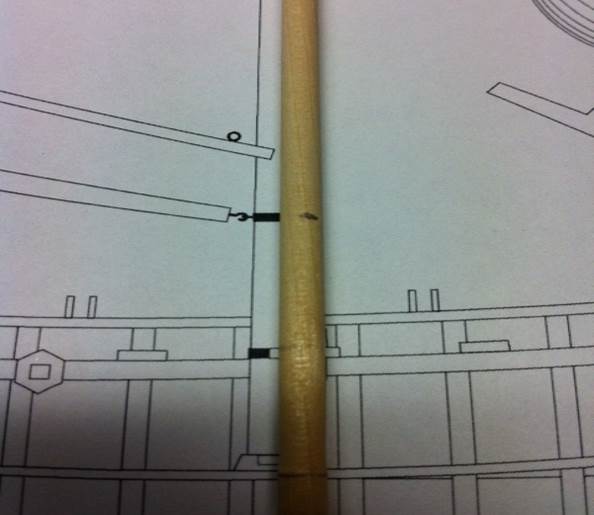
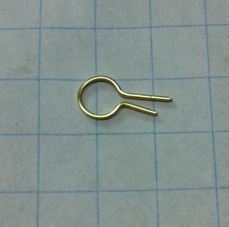
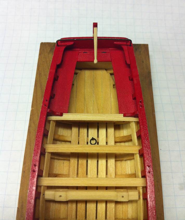
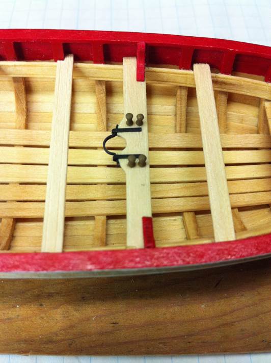
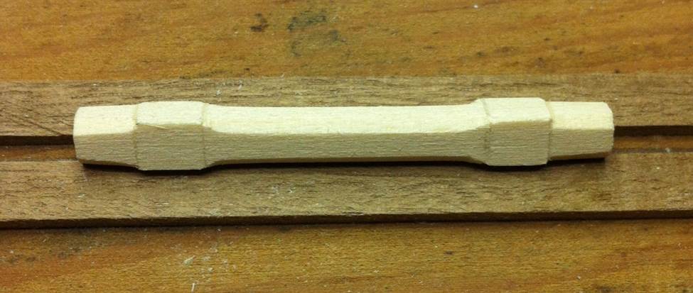
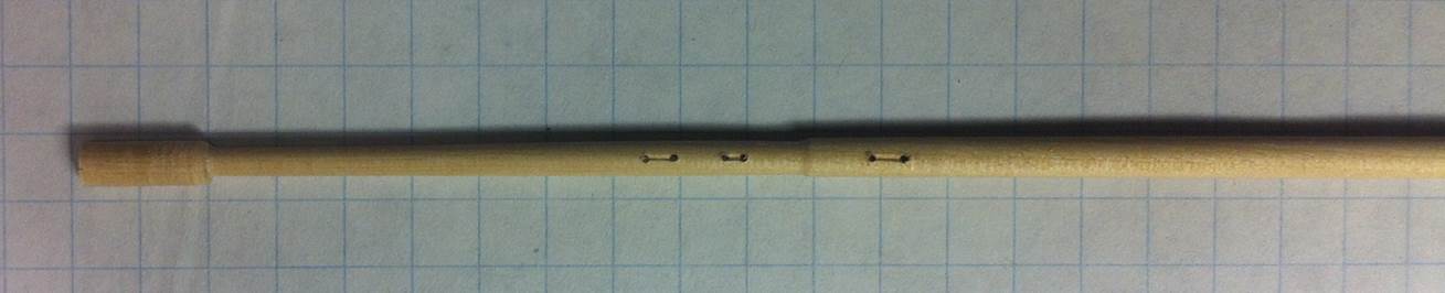
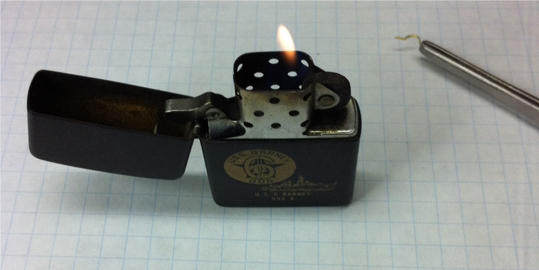
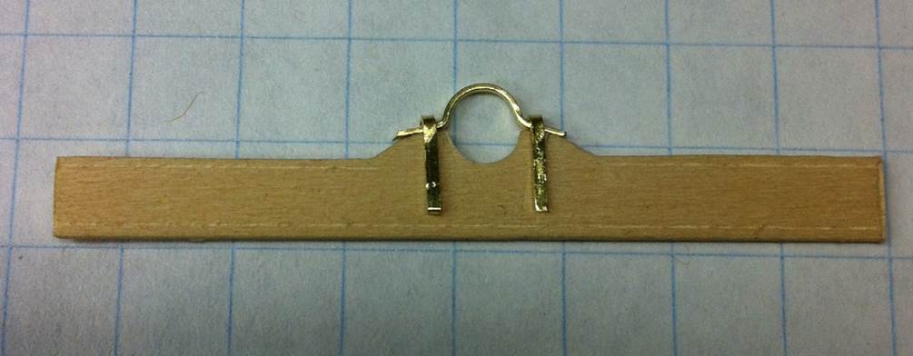
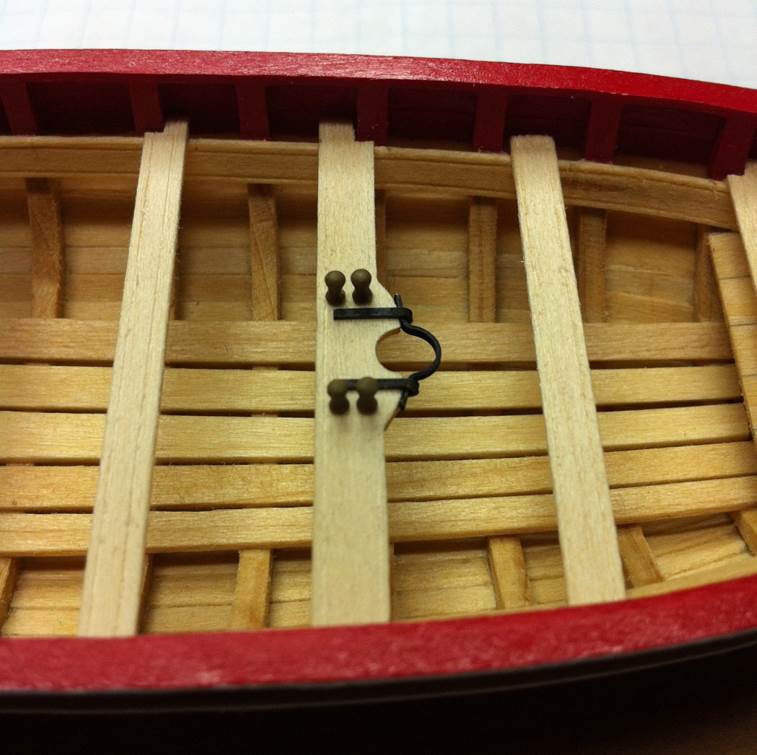
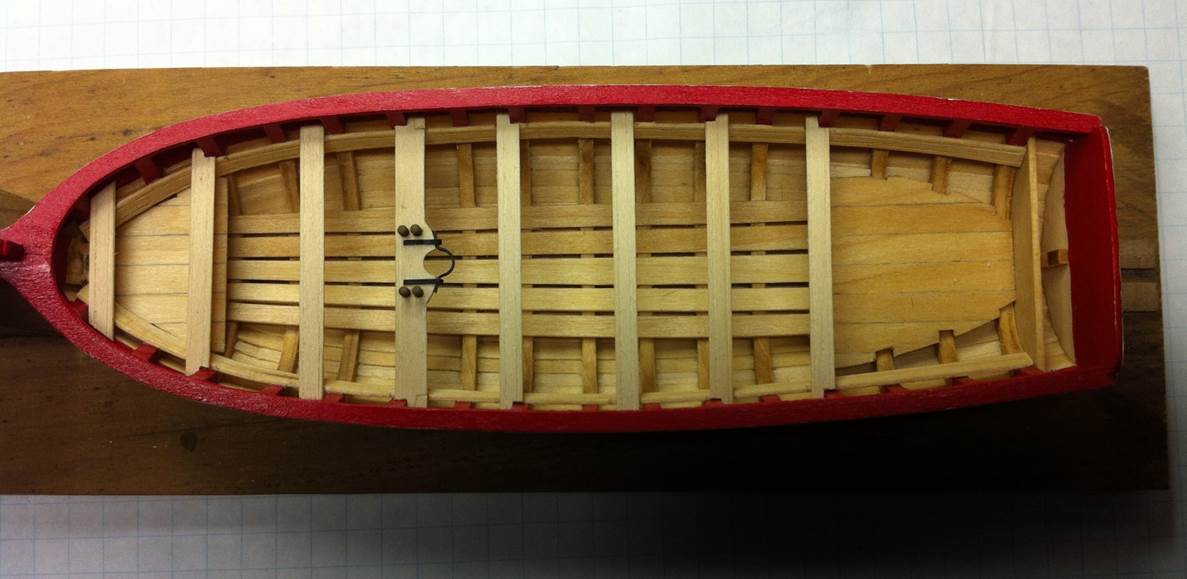
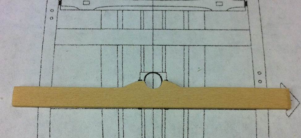
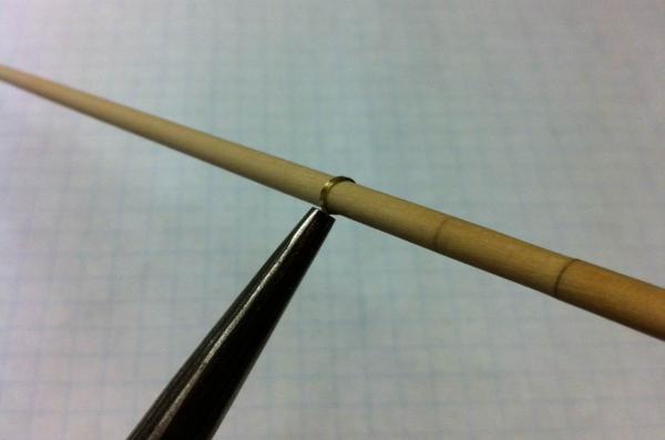
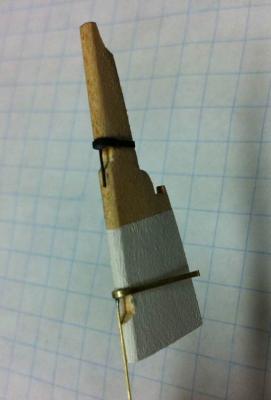
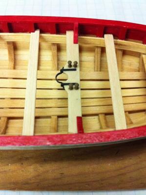
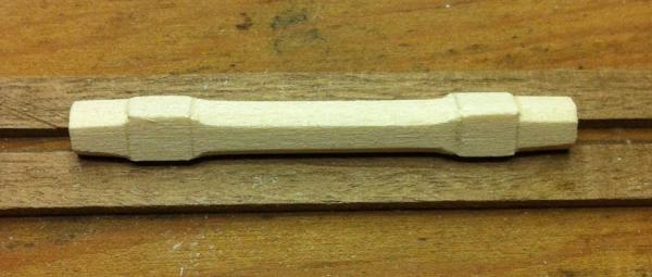
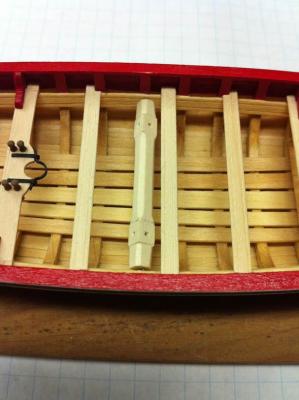
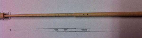
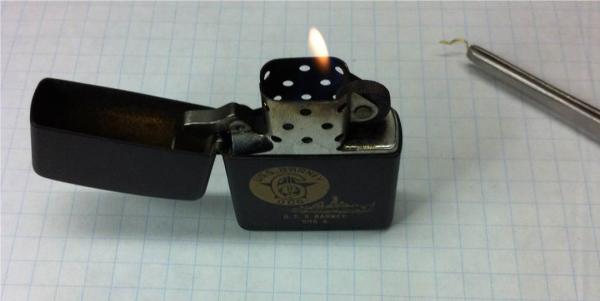
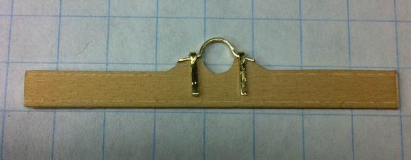
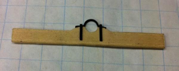
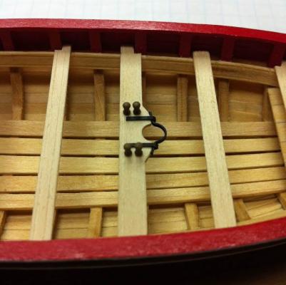
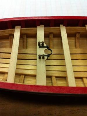
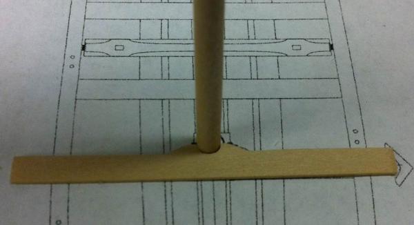
Time for another update... I took David's suggestion and cut the holes for the sheaves before turning the mast down to its final dimensions. Here's a look at the mast with the holes drilled. Then I turned the mast down the rest of the way. Here's the mast laid on the plans. Finally, I cut the grooves between the holes to simulate the sheaves. The instructions say the leave tenons at the top and bottom of the mast. I'm going to try to do that, but, at the top, there isn't a great deal of extra room. I might just cut the mast a little long and fit the extra into the ball truck. At the bottom, there's plenty of room and the tenon shouldn't be a problem. Once the mast was done, I turned my attention to the wide thwart and the mast hoop. I've found my new favorite modeling material: Birchwood Casey Brass Black! I started by cutting and forming the brass strip. I know that's a little out-of-order. I should have annealed it first, but it seemed to work alright. Then I passed the formed strip through a flame to get rid of any coating that might be on there. Here's what the formed pieces looked like, pre-blackening. I dunked the formed pieces in isopropyl alcohol, then rinsed them with water, then put them in the Birchwood Casey ... and watched the magic! Here's the ironwork installed. Looks good, right? Right. So now it's time for something tragic to happen. I drilled the holes for the four belaying pins. I painted the pins using Polly S acrylic Wood Tan. (Just happened to have some of that around.) There is not a lot of room for these four pins. My thwart must be a little more narrow than Chuck's because his look like they have more room between them than mine. I hope this doesn't make rigging too difficult. Then it was time to install the completed assembly in the boat. Measure, cut, fit, glue ... and here's the result. Anyone notice anything odd? How about a closer look? That's right! It's in BACKWARDS! I was really impressed with how good this whole thing looked and then I looked in the instruction book again. BACKWARDS! I installed the stupid thing BACKWARDS! Measure twice! Cut once! Arrrrrrgh! Once again, I was glad I was using white glue on this model because removing the thwart was fast and easy. Ken Quast, another model builder in our club, told me, when he messes up a part, it's usually faster to just make another one rather than try to fix a mistake. I really considered that, but this assembly took me the better part of a week to do. I thought I'd give fixing it a try before pitching it and doing it again. I put a couple of little patches on the notches I'd cut, then I cut new ones. I sanded the whole assembly and, although you can see where the old notch was, it will probably be hidden when the knees are installed. So there it is. All the thwarts are installed. I need to hit them with the Watco's Danish Wood Oil and then on to the inboard details. Dan

- 175 replies
-
- 4
-
-
- 18th century longboat
- model shipways
- (and 1 more)
-
Clipper Schooner is how I would describe her. The "Aberdeen Bow" was quite an innovation at the time. I found this published in the the Aberdeen Journal in 1848: 'The Messrs. Hall commenced framing the schooner from aft, and continued the frames until they reached the fore end of the keel. Thus far the work had proceeded when the builders suggested a deviation from the models, which they believed would prove to be a decided improvement. They proposed to run the stem out so as to form the cutwater, the effect of which would be to draw the waterlines finer at the bow and, as a natural consequence, the vessel would divide the water easily, the more buoyant forward, and of less registered tonnnage than if she were built on the old plan. The idea did not at first meet the views of the owners. A skeleton bow was then erected, and not a few of the curious examined it and were skeptical of the uncommon design. After due consideration, the owners gave consent to proceed with the vessel according to the skeleton model, and in that style she was finished and launched. The look of the schooner in the water was encourageiing. It was evident from the appearance of her waterlines that the idea of a perfect bow was realized, and some of those who were at first opposed to the project were now among the warmest commendators.' Dan
- 607 replies
-
- 2
-
-
- scottish maid
- artesania latina
- (and 1 more)
-
Scottish Maid was purchased in 1839 by Alexander Nicol and George Munro of Aberdeen for the purpose of competing with the Aberdeen & London Steam Navigation Company. She worked the Aberdeen - London trade for about 50 years. At the time of her building, tonnage was used to calculate various taxes and harbor duties. Tax changes in 1836 establsihed a ship's tonnage based on depth, breadth and length at half midship depth. Extra length above half midship depth was tax free, which drove innovation in hull design and construction. Looking for ways to improve speed and performance and take advantage of the tax benefits of a longer hull, Hall & Sons (her builder) tested various hull shapes in a water tank. They found the clipper desing to be the most efficient. The term clipper was relatively new in 1839. Although the re is some evidence that the term was in common use in the late 18th century, there is no written reference to a clipper ship until 1830 and the term was loosely attributed to any fast-sailing ship. Scottish Maid was very fast. She regularly made the 450 mile run from Aberdeen to London in 49 hours, averaging 9 knots. Dan
- 607 replies
-
- 2
-
-
- scottish maid
- artesania latina
- (and 1 more)
-
That's a good suggestion, David. Thanks! Dan
-
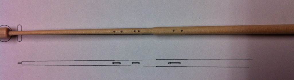
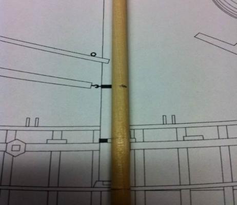
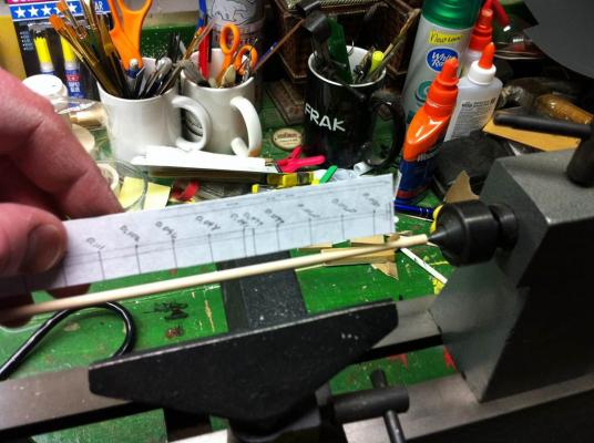
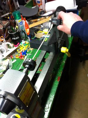
I did some work on the mast last night. Using material commonly found in my house... I made a template for measuring the mast. I just cut out the measurements I'd made on the plans and glued them to a piece of cardboard to stiffen it up a little. I chucked the stock into the lathe and started tapering it. Periodically, I measured it using the digital caliper. I didn't finish the project last night. I was starting to question the wisdom of taking this mast down to 0.050" in diameter. That's very small and I'll need to cut the holes for the sheaves in it, which will weaken it significantly. Has everyone been tapering the mast down that much? Anything I should watch out for, other than the obvious: snapping it off with even the slightest stress? Dan

-
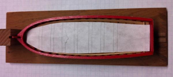
Here's the boat with the narrow thwarts in place. Dan
-
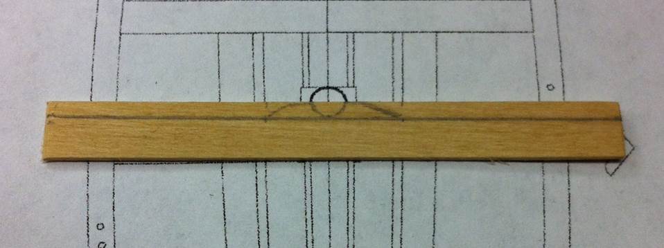
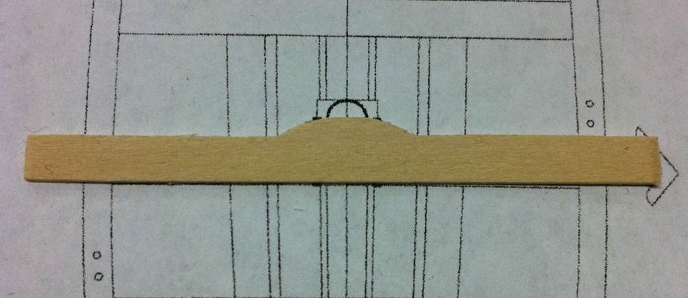
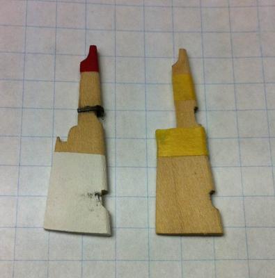
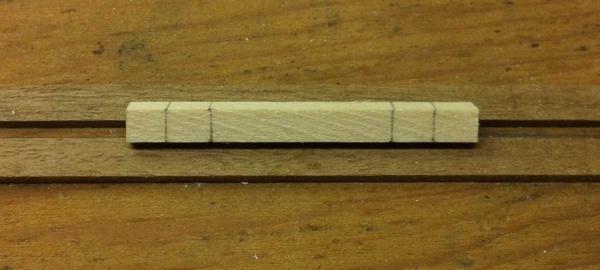
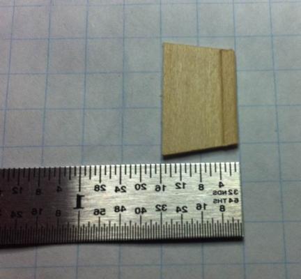
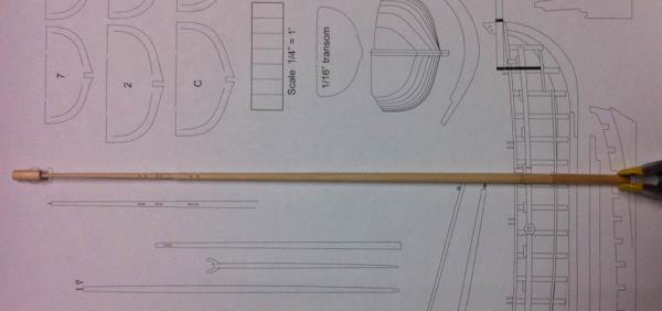
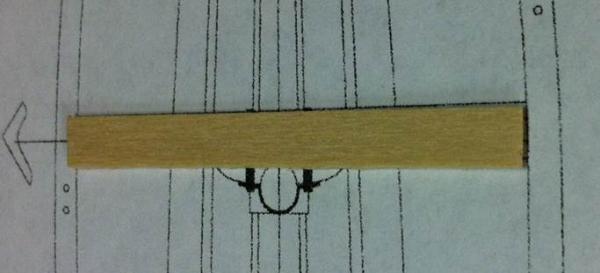
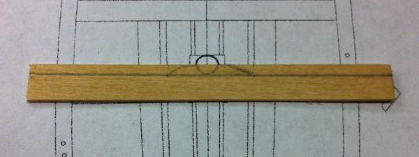
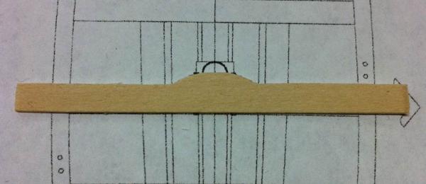
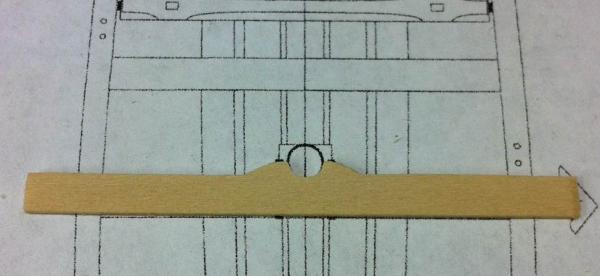
I've made some progress on the thwarts. I just realized I neglected to take a picture of the boat with them narrow thwarts installed, but here's what I did manage to document. My first attempt at getting the thwarts in didn't turn out all that well. I scribed the grooves in the stock and cut it to the lengths needed, leaving plenty of extra for trimming. I marked the locations on the risers based on their locations on the plans. Then I looked at the pictures in the instruction book ... and they didn't match. I started putting the thwarts in based on the pictures. That was a mistake. The distances between them were off. I removed the ones that were clearly not in the right place. (They were the ones not lined up with the marks on the risers.) Then I made a simple template to help me get them installed and lined up properly. Everything went fine after that and they look really good, if I do say so myself. (Photo to follow.) That was it for the narrow thwarts. The wider one -- the one that accepts the mast -- is a little more complex. The instructions say this thwart should be "made using a 3/16" wide strip." Here's what a 3/16" wide strip looks like when placed on the plans. See? Too narrow. I happened to have a piece of 1/4" stock laying around. that dimension lines up with the plans better. Using a ruler, I drew the correct width on the stock and then free-handed the aft profile. I used the mast dowel to make sure I had a 5/32" semicircle for the cutout. Then I just cut it all out. My freehand drawing on the blank needed a little modification to get symetrical, but it worked out alright. Here's another thing. The dowel in the kit is warped. You can see it in this photo. I considered replacing it with a 5/32" walnut dowel I had, but then I thought I could make this one work. The warp only affects the end of the dowel, so I can cut that part out and have a straight dowel of the proper length. That's what's going to happen. I've been told my mast-making technique is a extreme. What's what I'm into: extreme model building. Grabbing a giant Mountain Dew, I donned my crash helmet, knee and shoulder pads and bungee jumped into it. On a copy of the plans, I recorded the width of the mast at 1/2" intervals, using a digital caliper to make the measurements. Next, I'll chuck the stock into my lathe and turn it down to the final dimensions. This isn't a big mast and that taper isn't that severe, so this should be fairly straightforward. More to follow. Dan

- 175 replies
-
- 3
-
-
- 18th century longboat
- model shipways
- (and 1 more)
-
For gray, I'd just go lightly with a regular pencil. Dan
-
Not too much progress to report, but I thought I'd post a quick update. I used the Watco Danish Oil finish that Toni has recommended. Check this out. It looks great. This finish required two coats. It's as easy to use as tung oil, but much less shiny. I had originally thought I would not finish the hull, but after finishing the interior, I think I have to ... for two reasons. First, that finish really looks good and I want the boat to have that warm color. Second, the planks are pretty thin on this boat after they've been sanded down flush. The finish soaked through them in one spot. You can see the darker area near the bow. On the stern, I got the same effect, only it discolored the transom frieze. I think I can correct this with paint. (Any suggestions would be welcome.) I don't think the finish soaked through the transom. I think it must have made its way through a small gap . There's no other way it could have gotten there. Dan

-
I just used the kids' colored pencils, David. I bought them at Michael's for next to nothing. There are lots of things I like about paper modeling. The models are inexpensive. They build quickly. It doesn't take up much room. (You could store all the tools you need in a cigar box.) And the tools you need are pretty basic, readily available and inexpensive. Dan
-
Great build log, David! It's really coming together. Dan
-
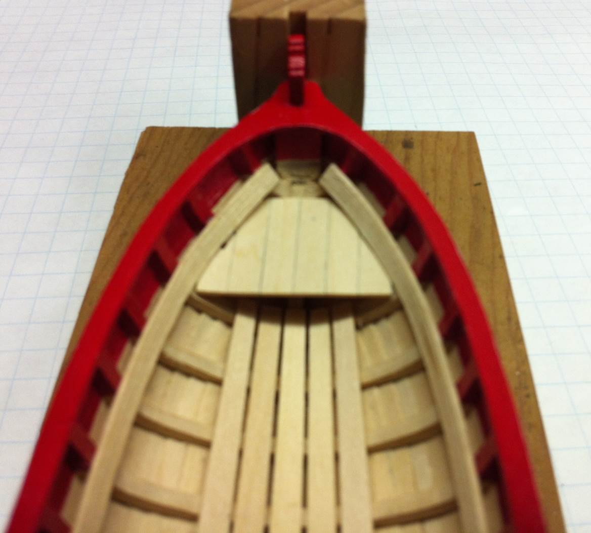
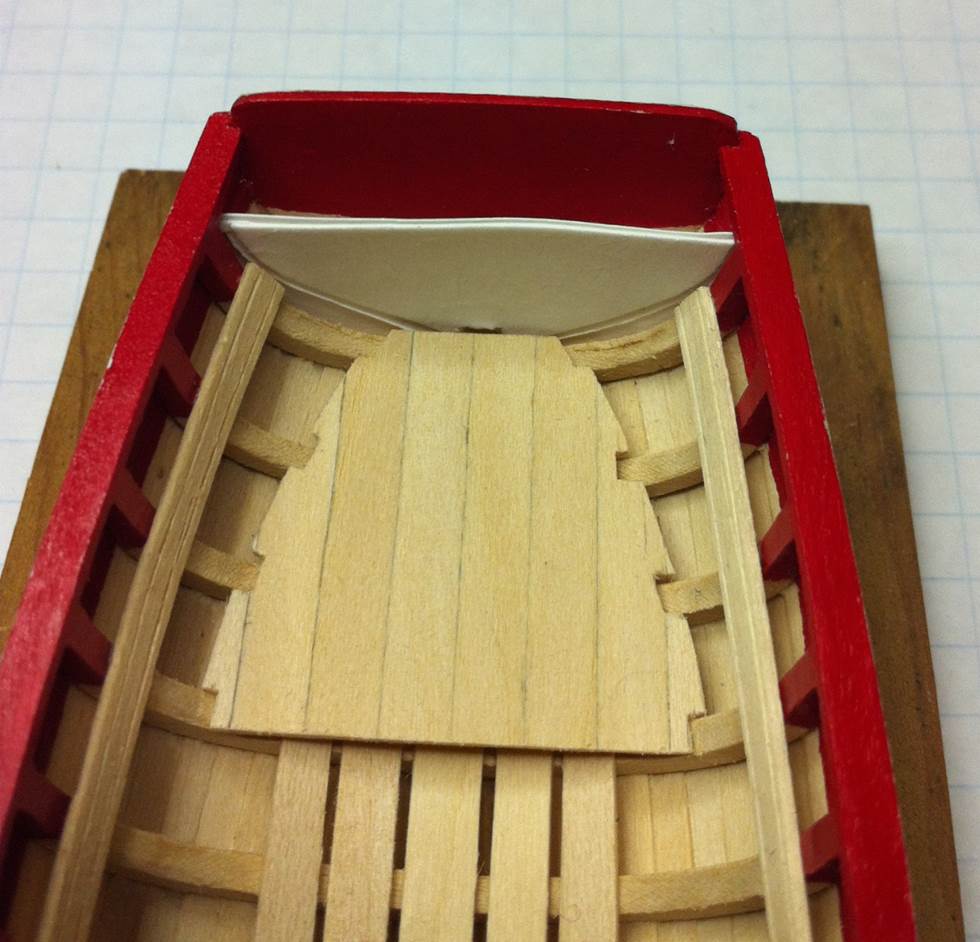
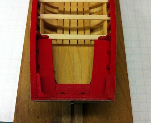
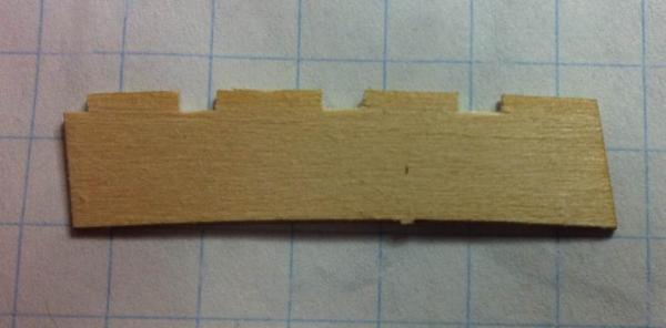
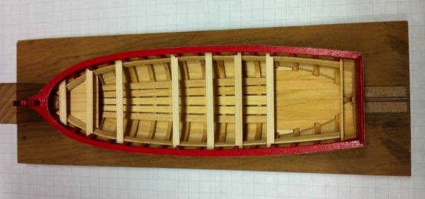
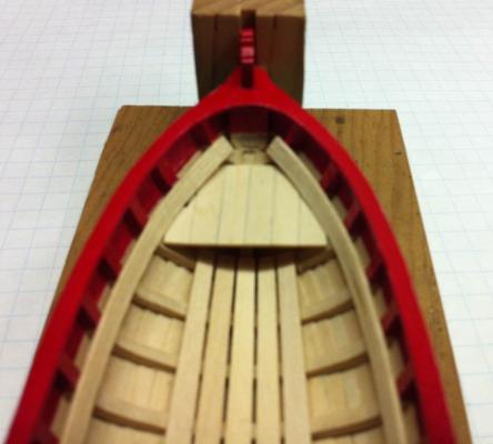
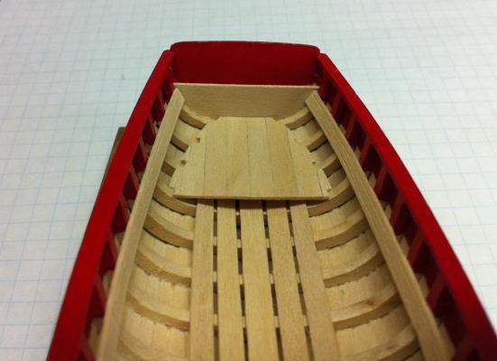
Last week was full of distractions and I got very little done on the longboat ... but what I did get done looks pretty good. The forward platform went in just fine. Making the risers was also pretty straightforward. I didn't complicate the scribing of the grooves. I just ran an awl against the edge of a ruler and scribed them in. A couple of passes was all it took to get some good looking grooves in them. (I did have one riser look a little more "fuzzy" than the other one. Don't know why, but it'll all sand out.) The amount of edge bending needed was a little more than I had initially anticipated. It took two trips to the glass plate to get enough bend in the plank to get it to sit correctly against the frames with a consistent measurement from the top of the cap rail. When I went to install the risers, I found that the forward platform was a little too high. When it was just the template sitting there it looked fine, of course. That operation wasn't that tough. I just made it a little smaller and sanded the frames a little bit more. Once the platform was back in, the risers went in without a problem. Then it was time to put in the locker bulkhead. Following the instructions, I made a template. The nice thing about using templates is the ability to alter them quickly and easily. I started out tracing the frame from the plans and then gluing that outline to a piece of cardstock. I cut out the template and found it was far too large to fit in the space behind the frame, so I cut it down ... too much. That was no problem because I just added another layer of cardstock and added in what needed to be replaced. That worked great. Then I cut a piece of basswood to size and fitted it in place. Now on to making the thwarts! Dan
- 175 replies
-
- 4
-
-
- 18th century longboat
- model shipways
- (and 1 more)