HOLIDAY DONATION DRIVE - SUPPORT MSW - DO YOUR PART TO KEEP THIS GREAT FORUM GOING!
×

Chuck Seiler
-
Posts
1,876 -
Joined
-
Last visited
Content Type
Profiles
Forums
Gallery
Events
Everything posted by Chuck Seiler
-
 I strongly suspect not. WASHINGTON was captured and the Brits took the lines of of her. Smithsonian has a couple pages of plans. PHILLY was raised and surveyed. Smith has a buttload of pages of plans for this....16 I believe. I am looking at an old copy of the "Smithsonian Collection of Warship Plans" and find nothing for Royal Savage. Since it burned, the British may not hav gotten any info from it. C'mon....can't you build a model based just on the picture?
- 175 replies
-
- 2
-

-
- washington
- galley
- (and 1 more)
-
Hey Mike, maybe we can get Ken to make ROYAL SAVAGE. I kind of question the wisdom of all those swivel guns on the quarterdeck. Seems kind of crowded. However, that is where the Ernie Haas painting has them. Philly is about 90-95% complete. I have not had a chance to get any photos. I will get some tonight.
- 175 replies
-
- 1
-
-
- washington
- galley
- (and 1 more)
-
Be careful with those swivel guns...you'll put somebodie's eye out. Seriously. They look a little awkward sticking up by themselves on the QD, but I can picture the added railing and anticipate they will look great. I look forward to your progress.
- 175 replies
-
- 1
-
-
- washington
- galley
- (and 1 more)
-
Don't forget to reinforcethat stem piece.
-
Floyd, I tacked the problem of bulkhead alignment with a 3 dimensional jig to get square (ish) in all 3 d's. Look at my blog...post #7. It shows a device which runs perpendicular to the keel and has lines parallel to the base. Assuming that each bulkhead is the same height on both sides (taking pains to ensure that), you can help eliminate the tilt by lining the top of each side of each bulkhead with a particular line. I see what you mean with the stem modification. By doingit that way you get the weak grain on the underside, but it is strengthened by gluing it to the centerpiece.
-
Floyd, Welcome to the fleet. Your discussion above brought back some bad memories of the scarph joint. I went back and looked at mine. I remember!!!!! The overhang of the stem part is above the overhang of the keel part. This caused me some probblems. I would have prefered the other way. That way I could have fitted the stem to the hull, then fitted the keel into the stem and hull. I have another kit, so I may do as you did and make the stem and keel from boxwood and do the joint differently. How did you eventually do the stem piece so that it doesn't snap off?
-
...although I suspect I will do well in the "Rowboat with 2 or more big-assed guns" category.
-
David, Thanks, I appreciate the compliment. Evenon it's best day, though, PHILLY will be hard pressed to beat some of the very fine models that are normally entered. I am happy just to participate and have thousands of people see it.
-
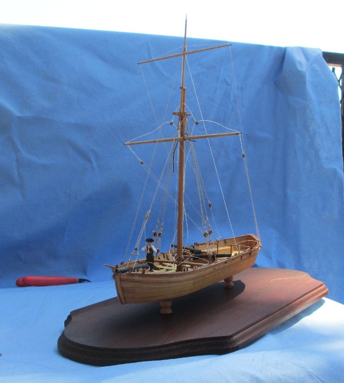
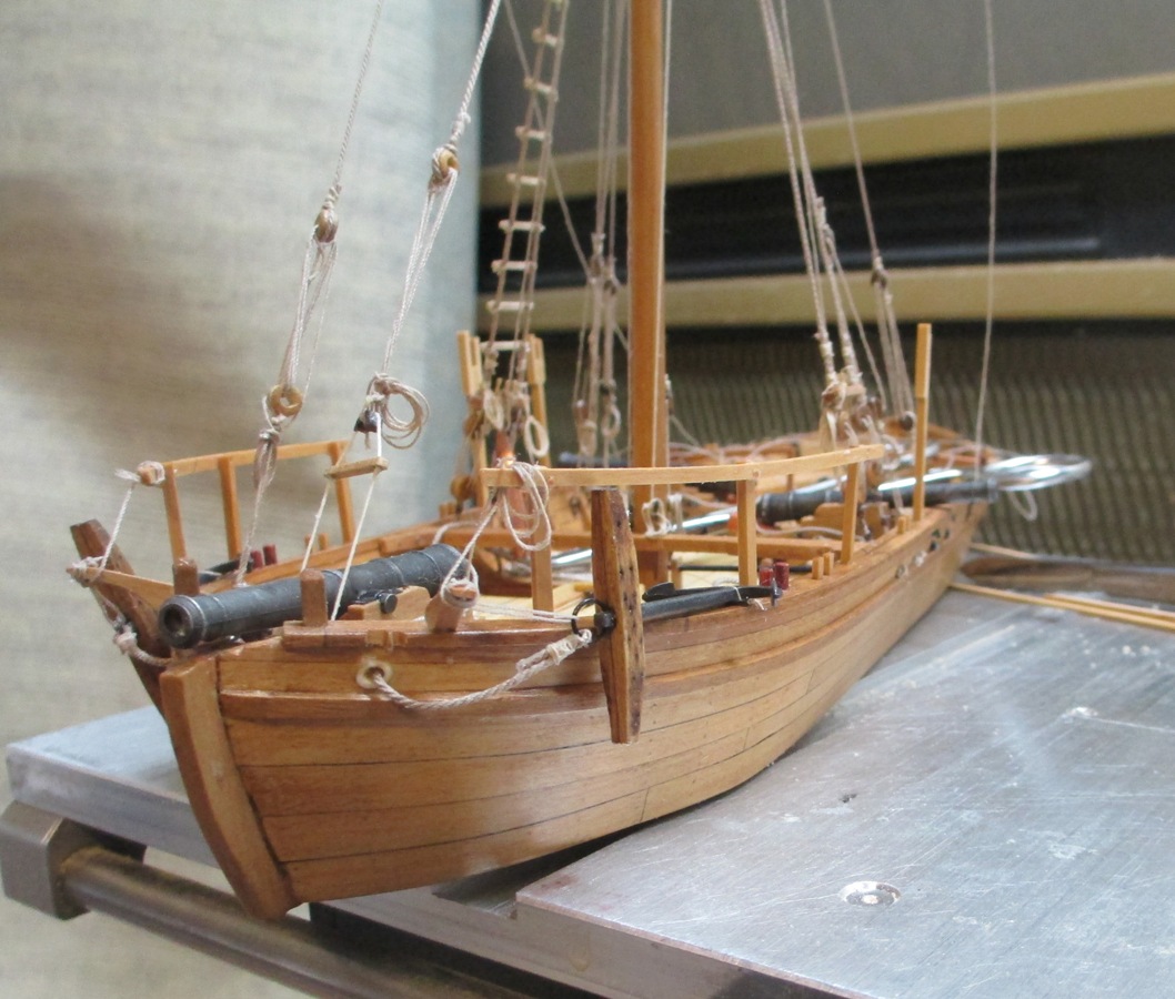
Behold! A Masterpiece! NOT!!!!! Here is what Philly will kinda look like when complete. As mentioned before, I am trying to get her ready for entry into the County Fair in June. Entry (with pics) were due today. Hopefully the guys that build tables and guitars won't look too closely. The goal was to get it to where it looked reasonably like a completed model. I got to the shrouds and found that I had made them too short. They did not stretch as much as I had anticipated. Good news is that I get to redo the seizings on the shrouds, which I did not like. I also got to get a better look at the lay of the lines I determined that I WILL have to glue on the yards, but will be able to remove them at some future date if need be. Philly is already stripped back down to basic infrastructure and construction will begin again in earnest on the morrow. Captain Benjamin Rue inspects the rigging job. "I have morons on my team!!!!"

-
I'm about to demolish that myth.
-
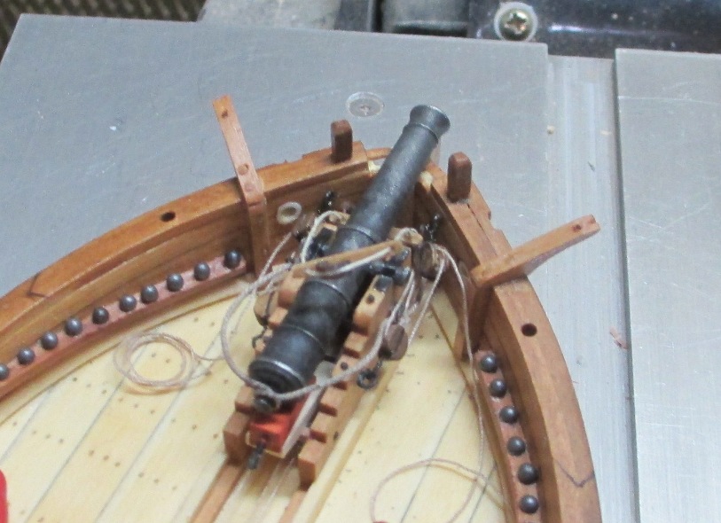
Mike, It is. I got them from LUMBERYARD. The blackening ears off if you handle the guns, but I decided not to paint or otherwise re-blacken because I thought it gave the guns an interesting look. It goes well with the rustic motif. What do you think?
-
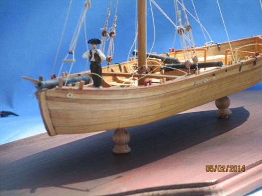
Bow gun and fore stay spreader mounted.

-
Now that I have the forward gun mounted, I will give him a 12 pound aluminum HOWDY.
-
We have to head over to Valcour Island first. Guy Carlton is waiting for us.
- 175 replies
-
- 1
-
-
- washington
- galley
- (and 1 more)
-
David, Take the ol' mini torch to the brass until it gets red hot. Quench it. Repeat. Mike, Those are actually lead from an old shotgun shell. I guess I should have painted them, eh?
-
BEESWAX FOR SHIP MODEL RIGGING
Chuck Seiler replied to vas1949's topic in Masting, rigging and sails
Floyd, I agree. The Chuck-rope I have is fuzz free and hangs well. Rigging starts in earnest on PHILLY tomorrow, so we shall see. I wanted to test to see if the microcrystalline detracted from the look of the line, as my experience with beeswax had. It did not. -
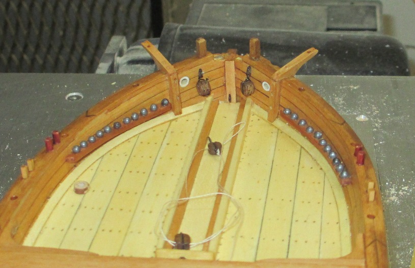
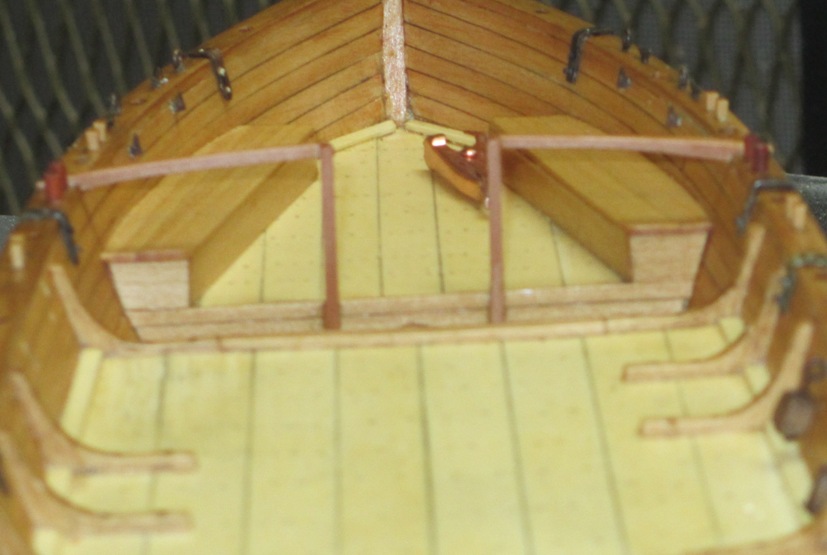
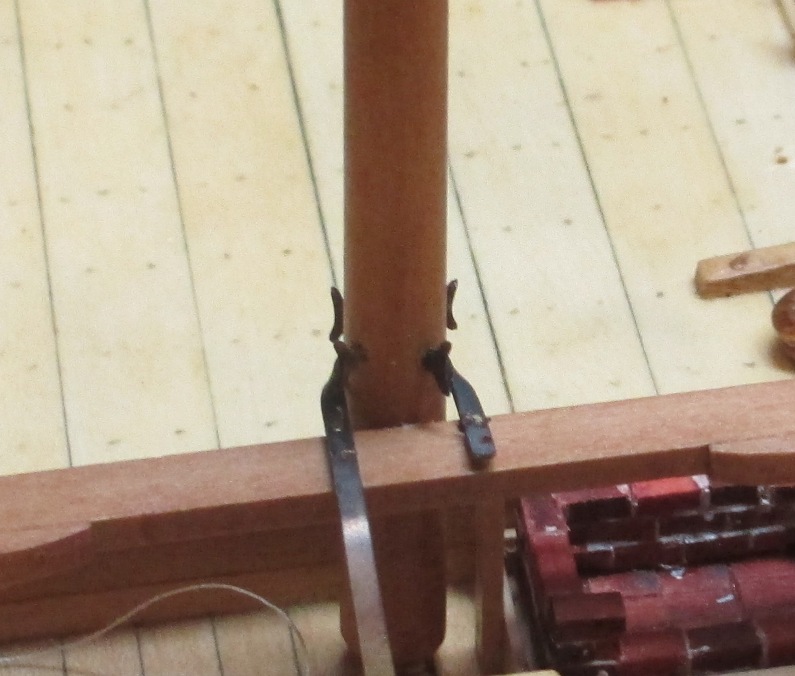
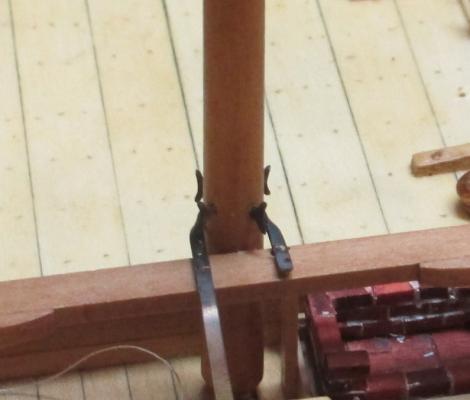
Progress continues. The catheads (more like cat whiskers) installed. The bow area s very busy, and it all has to be resolved before the mast is installed. The first thing that has to be done is the installation of the shroud spreader. This attaches to the eyebolt at the base of the stempiece, at the forward end of the gunslide. I will pull the eyebolt, attach the spreader and re-install. The purpose of the spreader is to allow the mainstay to be mounted to the stem piece without blocking the forward gun. Next, the forward 12 pounder has to be installed. This includes a number of blocks and eyebolts. The after deck railing is installed. Whose bright idea is this? Any wagers as to how long before I snap this thing off? Mast support bracket. I was concerned that I would have problems twisting the brass the 90 degrees on each side in order to secure it to the mast support beam. No trouble. I annealed the snot out of it (certified snot free brass) and it twisted very easily. A side benefit seems to be that snot free brass is also blackened, so I don't have to use blacken-it. The mast goes up tomorrow. Huzzah!!!


-
BEESWAX FOR SHIP MODEL RIGGING
Chuck Seiler replied to vas1949's topic in Masting, rigging and sails
Like many in this thread, I had heard that beeswax s slightly acidic and non-good for rigging over the long haul. In addition to that, I don't like the way it squishes down the line. I got some conservator's wax (microcrystalline) called "Renaissance Wax" on Amazon. A little pricey, but not overly so. I tried it on some of my Syren company line and I am happy with the result. -
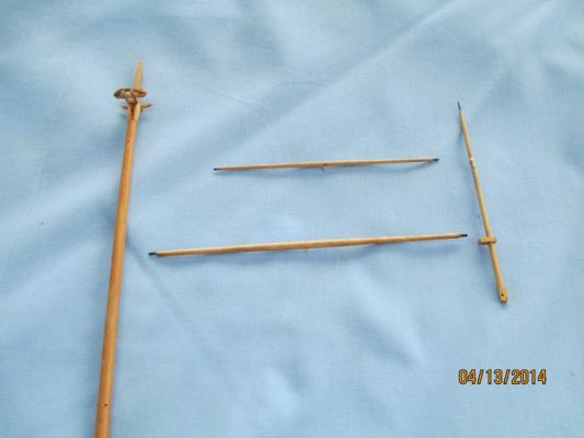
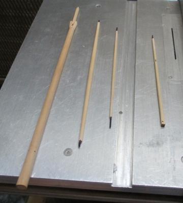
Crap...I didn't know there would be a test. I was experimenting with a couple colors, so I am not entirely sure but mostly sure. Crosstrees are cherry (two coats). Yards=1 coat of golden oak then one coat of 'natural'. Masts=either 2 coats of golden pecan and 1 of natural, or 3 coasts of golden pecan.
-
JSG, It's not your computer....I cannot see them either.
-
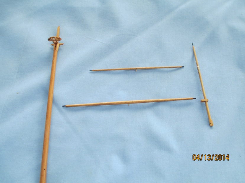
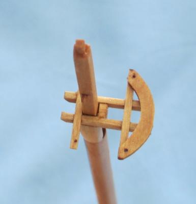
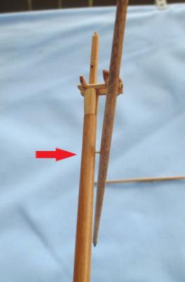
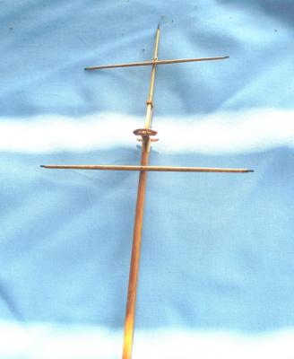
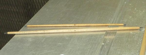
Mast and yards stained and ready to assemble. Cross tree. Nothing fancy...gets the job done. Now I show you what the holes are for. I put a peg in the yard and attach it to the mast. (see arrow). No need for glue. This holds it in place while the rope bridle is more for show. I was taking pics outside on the patio. It was a bit overcast, but lighting as good. As I was ready to shoot this, the sun broke thru and put a kibosh on the lighting. Mast assembled. Except for the crosstree, nothing will be glued and can be disassembled in the future.
-
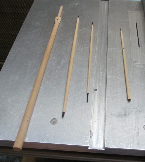
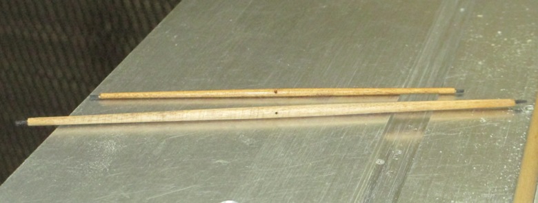
Progress continues. I need to post n order to avoid slipping to page 3. This weekend I am working on cats and dogs details, such as mounting eyebolts, bolting in the swivel gun brackets...and stuff. I am also working on the mast and yards. Last week I got most of the wood work finished for the mast and yards. I am holding off on the knotty look for now. Mainmast, topmast and both yards started off as square stock and were turned down in my highly sophisticated lathe...the main was chucked on the ol' Craftsman drill, while everything else went into the Dremel. The main was roughly octogonalized. This allowed me to drill the holes for the cleats before I rounded it off. Similarly, I drilled holes into the center of the yards. This helped me keep symmetry and I will be using the holes later.
-
Jay, Thanks for the videos. Reading how to do it is one thing. Watching it is another. The light bulb comes on.
-
Larry, What you say may be true. Looking at various pics of the actual PHILLY, I see it is pretty rough all over. Not sure how smooth it was to begin with. I have no good shots of the whole mast. The one in post #59 and I have one more with a view slightly higher up. Those bumps/knots are definitely prominent. How noticable would they have been 200 years ago? Who knows. I am going with the smooth mast for the Fair presentation. It gives mew time to think about it.
-
WQ, Sorry, I missed that. No offense intended. I wanted to emphasize the point because I found many new modelers (including myself) don't necessarily consider that. It wasn't until I started studying ship's internal structure and how ships were really made that I fully understood the process.