


_SalD_
-
Posts
815 -
Joined
-
Last visited
Content Type
Profiles
Forums
Gallery
Events
Posts posted by _SalD_
-
-
-
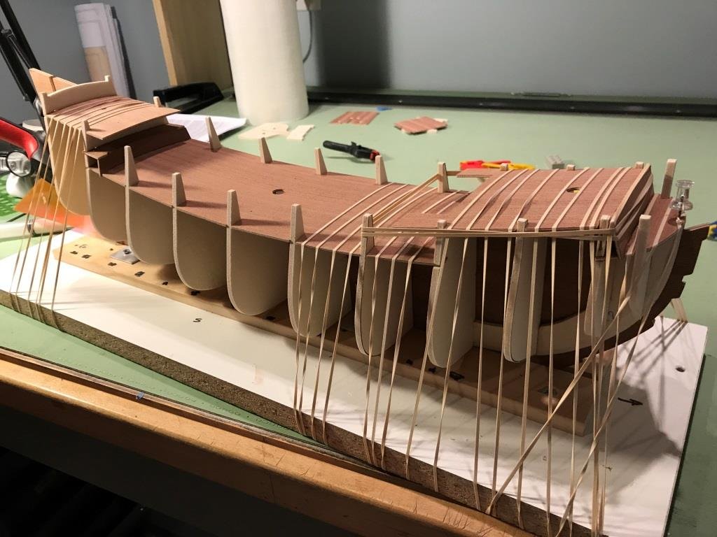
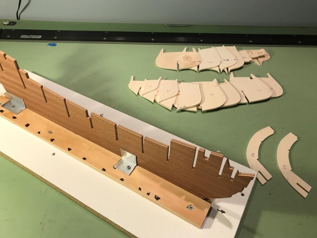
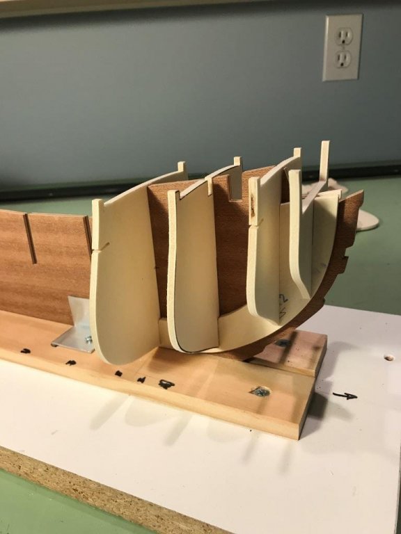
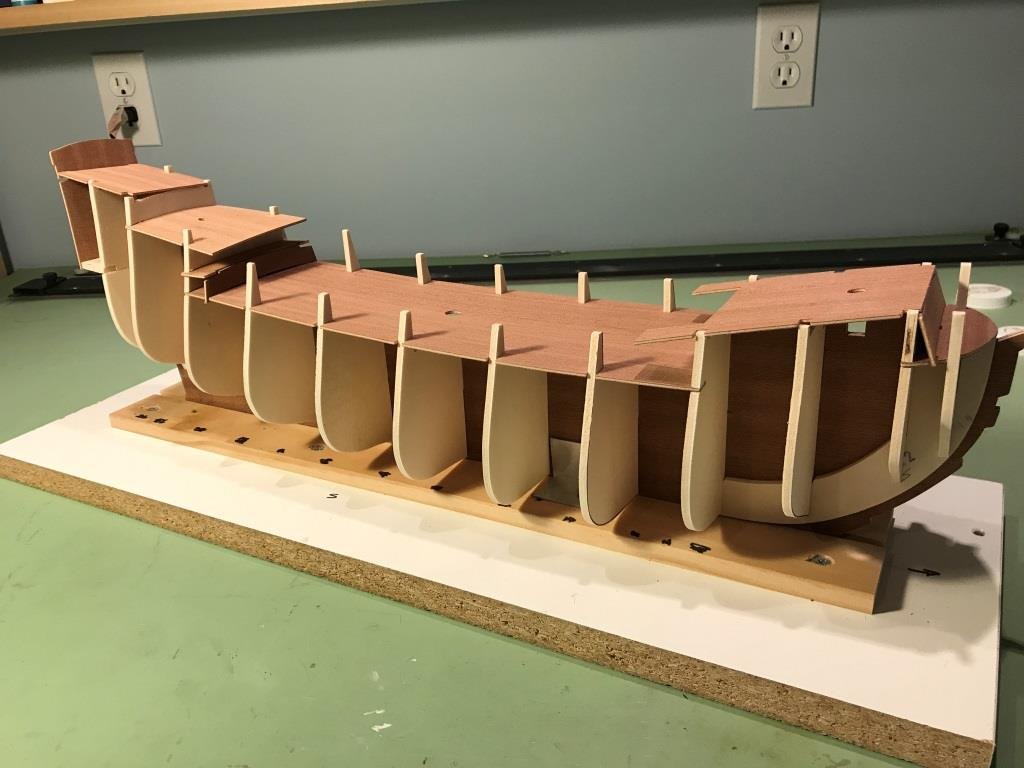
Continuing with the deck installation, the forecastle and quarter deck were glued in place.
- jay, Richard Griffith, Elijah and 4 others
-
 7
7
-
-
-
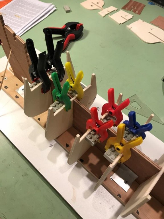
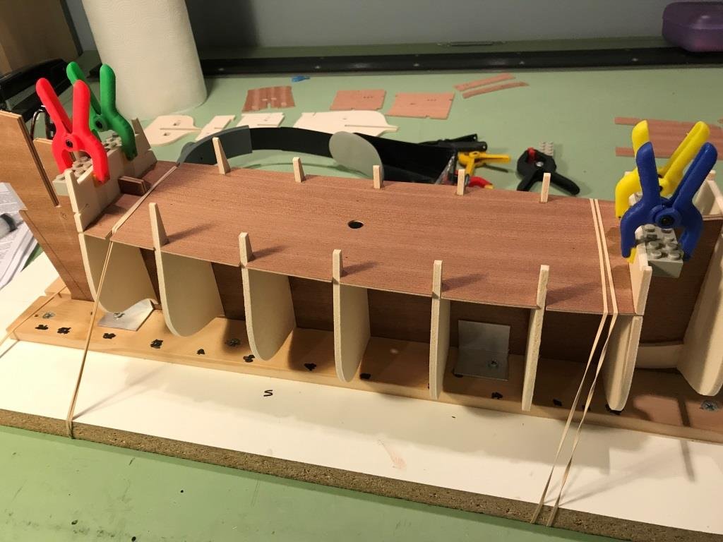
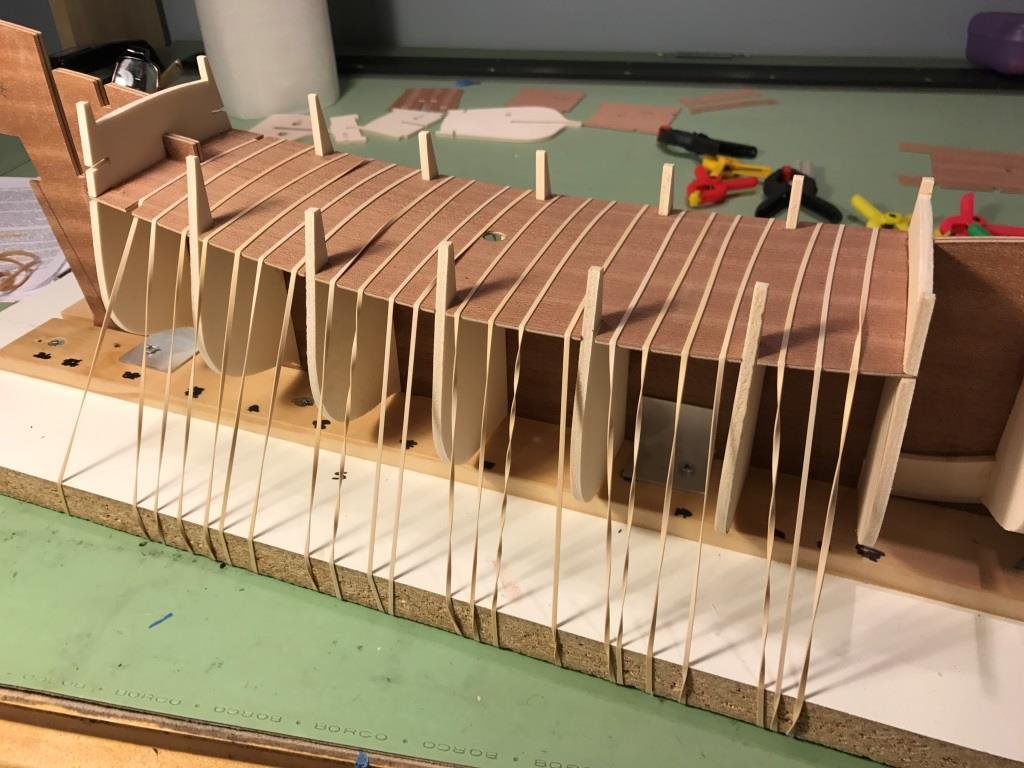
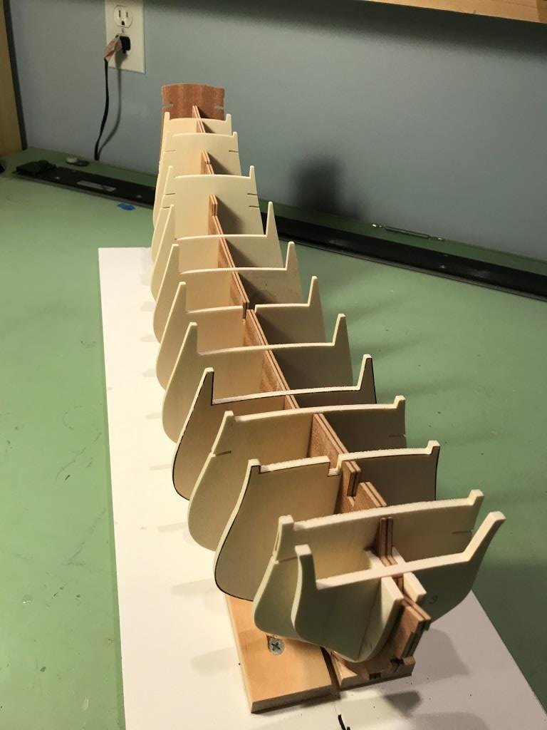
Starting to reassemble the bulkheads for their final placement on the BF using clamps and my trusty Legos.
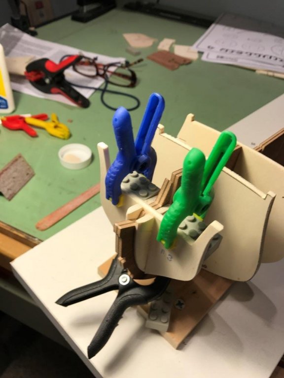
More clamps and legos
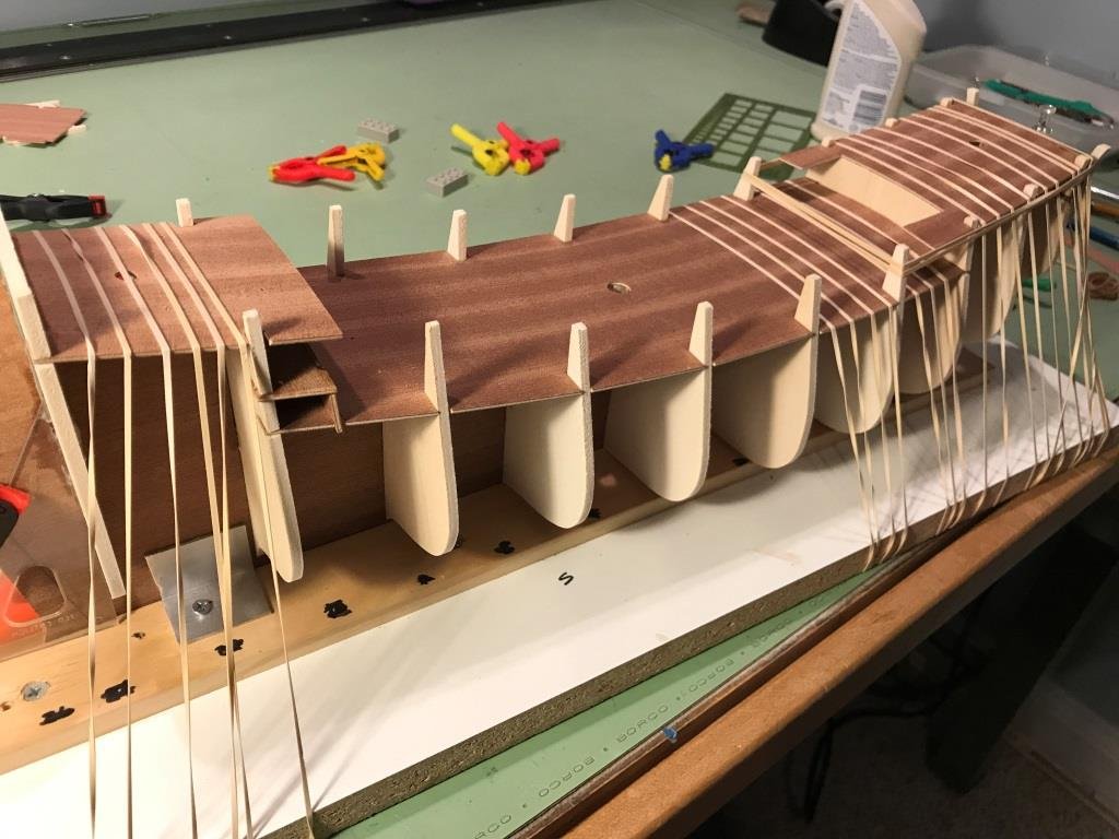
Setting the main deck. Reminds me of something out of Gulliver's Travels. The rubber bands worked out nicely because they pulled the deck down along the curvature on the bulkheads.
-
On 6/24/2017 at 7:24 PM, Elijah said:
Looking good! What would you say the overall quality of this kit is at this point?
Thanks Elijah, From what I've looked at so far the parts appear to be of good quality, I haven't looked at any of the blocks or fittings yet so my opinion may change.
On 6/24/2017 at 8:30 PM, Jack12477 said:Congrats to your daughter on her graduation. We both had a milestone to celebrate, my youngest daughter received her Doctorate in Education (EdD) this past April.
Point of interest on your Steamboats research - the Great Lakes steamboat SS Columbia is headed our way for restoration at the Hudson River Maritime Museum (https://hudsonvalleyone.com/2017/04/30/s-s-columbia-projects-steamy-dreams/ ) and Columbia Project . I'll let you know when she arrives.
Congrats to your daughter too, and thanks for the steamboat info.
-
I had mentioned before how lacking the instruction manual is but I had to laugh because although this is an advance kit the manual states and I quote, ‘… model may be constructed with a few standard tools, a hammer, a few small files, pliers, a pair of scissors, a knife cutter, sand paper and some glue…’ Hope the wife doesn’t see this or there go all the tools I was going to buy.

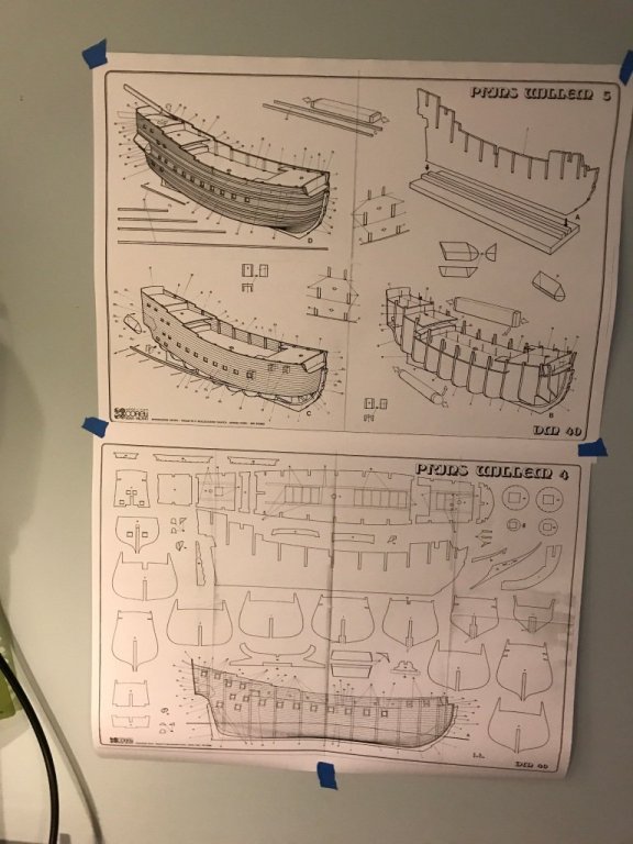
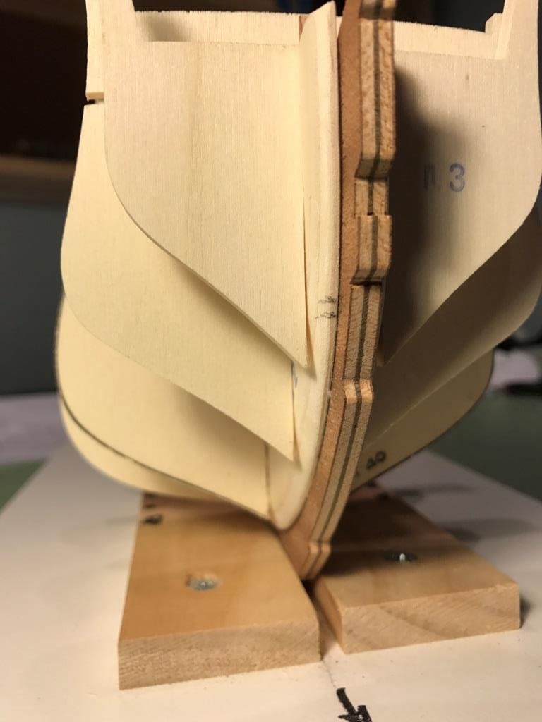
Unlike the Syren model bulkheads which came laser cut but still on large sheets this kit’s bulkheads are all cut out for you. The bulkhead former (BF) was also pre-cut and had no warpage at all.
The directions recommended to dry assemble all the bulkheads and decks prior to gluing anything in place. I’m glad I did this because there are some bulkheads that can’t be installed without installing the decks along with them. The decks are loosely installed so they appear a little crooked. All the slots in the bulkheads needed some sanding for them to fit properly on the BF.

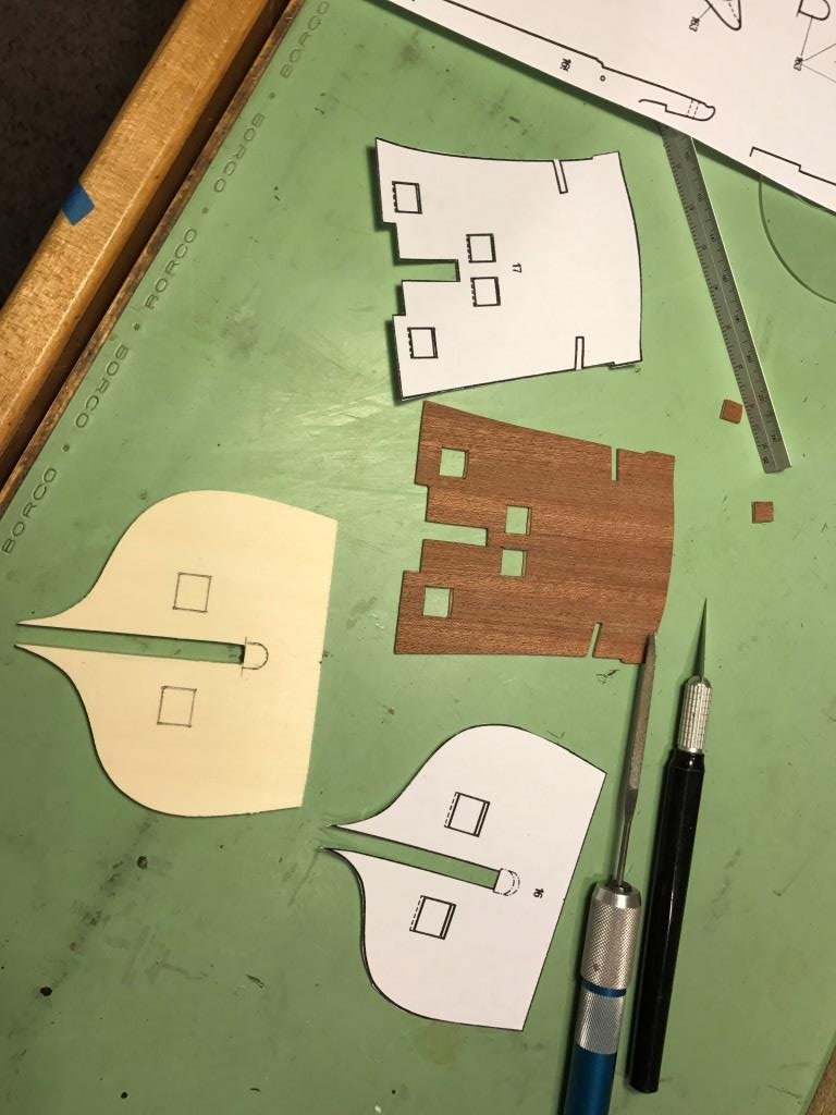
I decided to do some preliminary shaping of the two bow fillers before permanently attaching them to the BF. This is done so the hull planking runs smoothly to the bow.
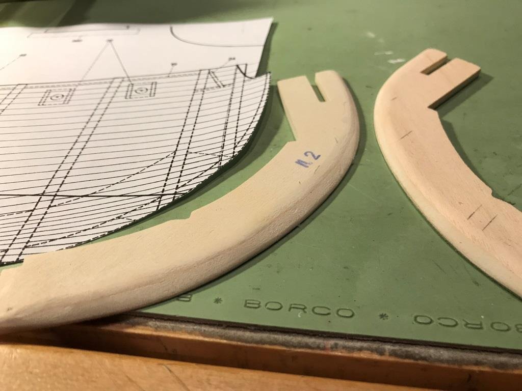

The last task to be done prior to reassembling everything and gluing in place is to cut the gun ports from the stern bulkheads. Making a copy of the bulkheads from the drawings, I cut them out to use as patterns to locate the gun ports. The ports were cut using an x-acto knife with a #11 blade and then filing the edges.

-
-
-
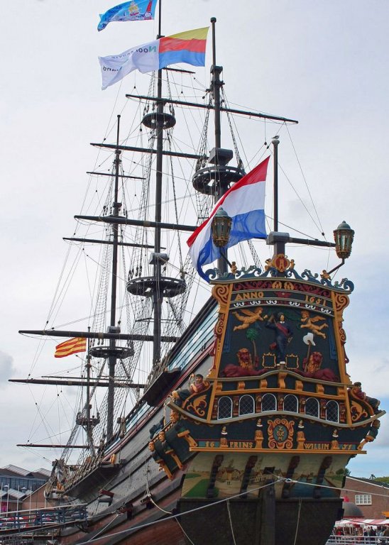
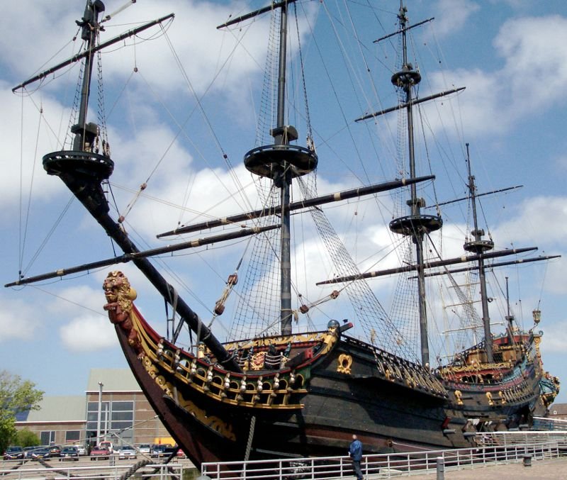
Hello all. I had debated back and forth as to whether or not I would do another build log and I guess you can tell what I decided. This will be my third kit built ship and decided on the Prins Willem by Corel. Prior to this I had attempted a scratch build of a sidewheeler steamboat but came to the realization that I’m not quite ready for that leap.
A little background information on the ship for those interested.
Owner: Dutch East India Company
Built: 1649-1650
Maiden voyage: May 5, 1651
Sank near Madagascar 1662 due to violent weather
Crew of 276
Displaced: 700 tons
Length: ~137 ft
Armament: 32 guns
A replica was built in 1985, but was destroyed by fire in 2009.
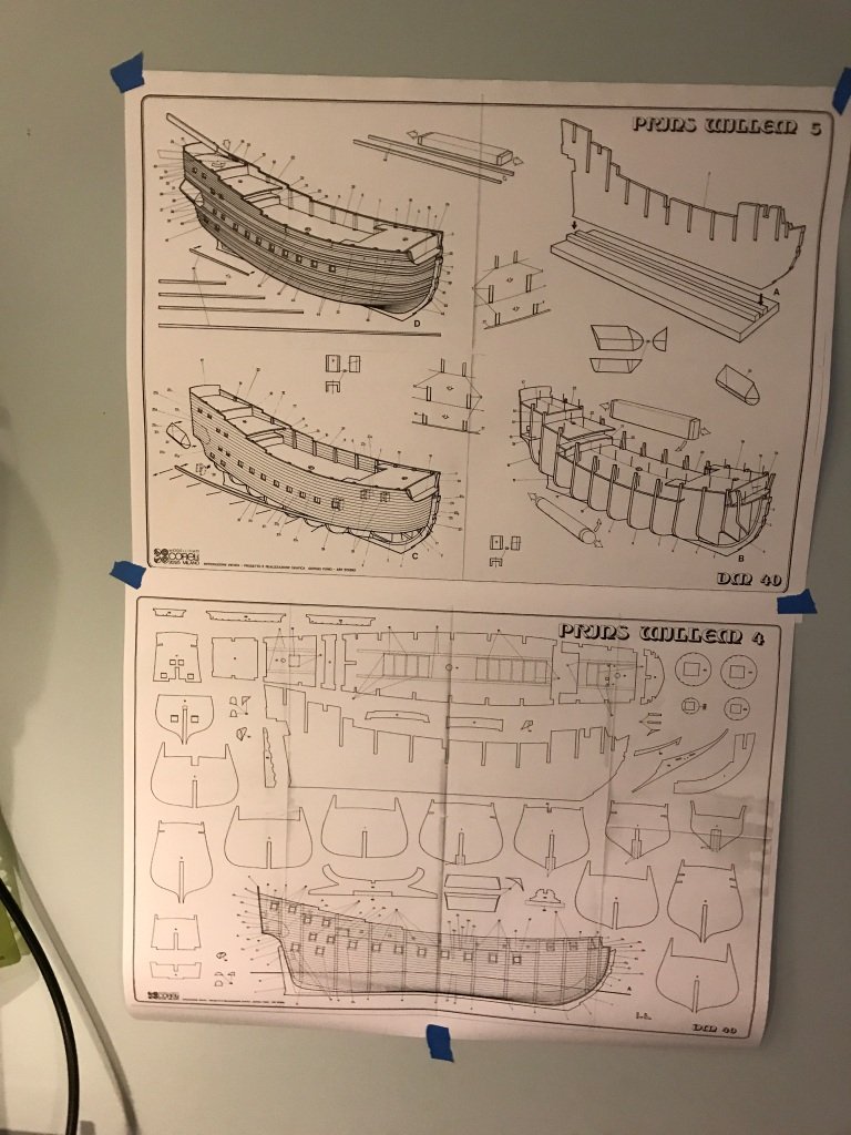
The kit was purchased through Model Expo and although it was back ordered it only could two weeks to receive. The model scale is 1:100, with a finished length of 29-1/2” and a height of 23". The kit is POB with laser cut wooden frames and the hull is double planked. There are quite a few parts to this kit and even though I know I should do an inventory of them I am forgoing that task and will check for the required pieces as I proceed. Fingers crossed.
Obligatory exterior and interior box pictures.
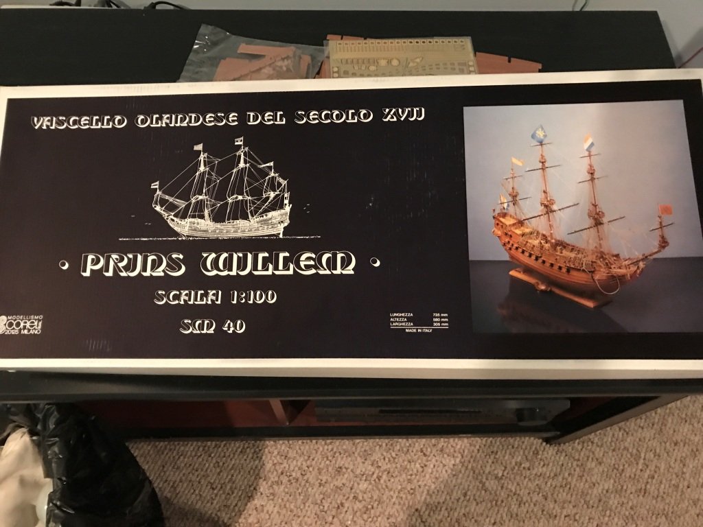
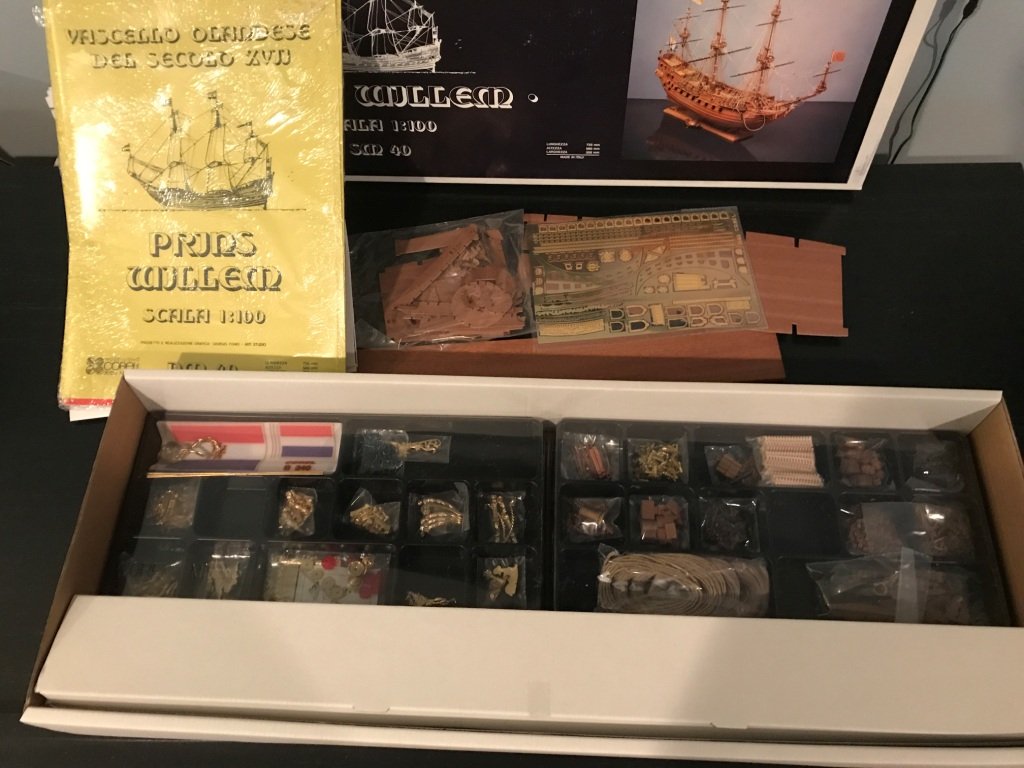
There are ten sheets of drawings which appear to be quite good, the instruction manual however is a little lacking.
- Robin Lous, hexnut, Elijah and 5 others
-
8
-
Nathan, For the style of text it will depend on what font's are available with the cad software you are using. I use Autocad and use their 'simplex' font for the majority for the dimensions and text. As far as text height I prefer text that is 3/32" high for dimensions and text, for titles I scale the 3/32" text up by 1.5 or 2 times.
For drafting the ship I've found using a scanned drawing as an overlay works well. It's also easier to pull dimensions off the scanned drawing than the hard copy. these are just my opinions and seem to work well for most cases.
-
I'm not exactly sure how a kit can be more of a poor choice if it has bad, difficult wood and crappy instructions, short of pointy wood dowels leaping out of the box and repeatedly stabbing you in the face every time you sat down to work on it. So yeah, I'd say reconsideration is a good plan.
Are you just looking for something galleony or were you interested in that specific kit for some reason? If you're in mood for galleon and race-built is ok, I recently purchased the Victory Revenge and it's excellent.
vossiewulf,
That's quite the visualization... pointy wood dowels leaping out of the box and repeatedly stabbing you in the face


I had thought I was ready to try a scratch built model but I think I need to fine tune my skills a bit more before jumping onto that band wagon. Also while building a case for my U.S.S. Syren and really taking some time to look at all the work I had done on her I sort of got bit by the rigging bug again and decided to build another sailing ship. I'm basically looking for a masted sailing ship that's somewhat different than the one I just finished. I'll take a look at the Revenge.
- Canute, Harmstronginga and mtaylor
-
3
-
-
-
-
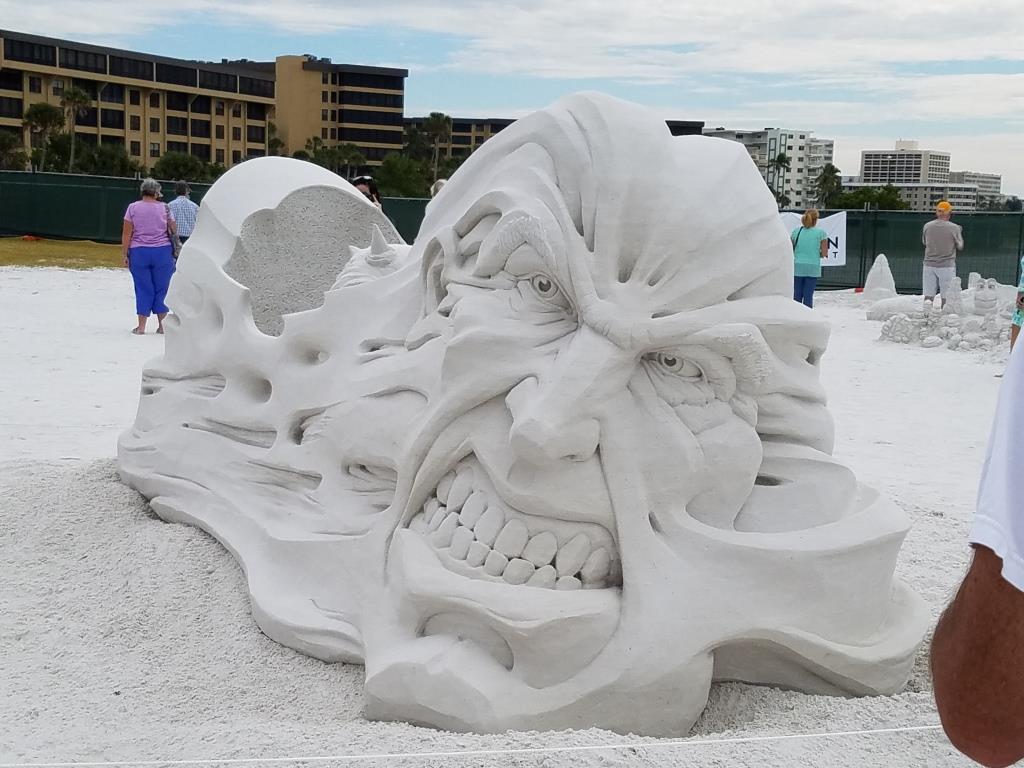
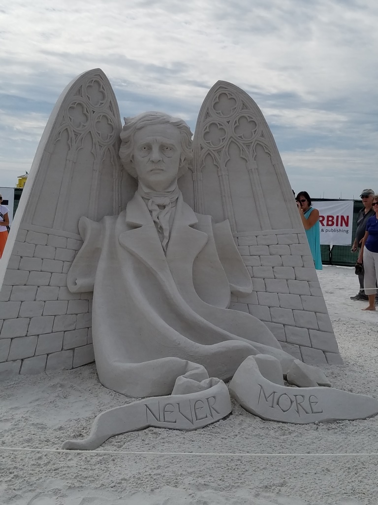
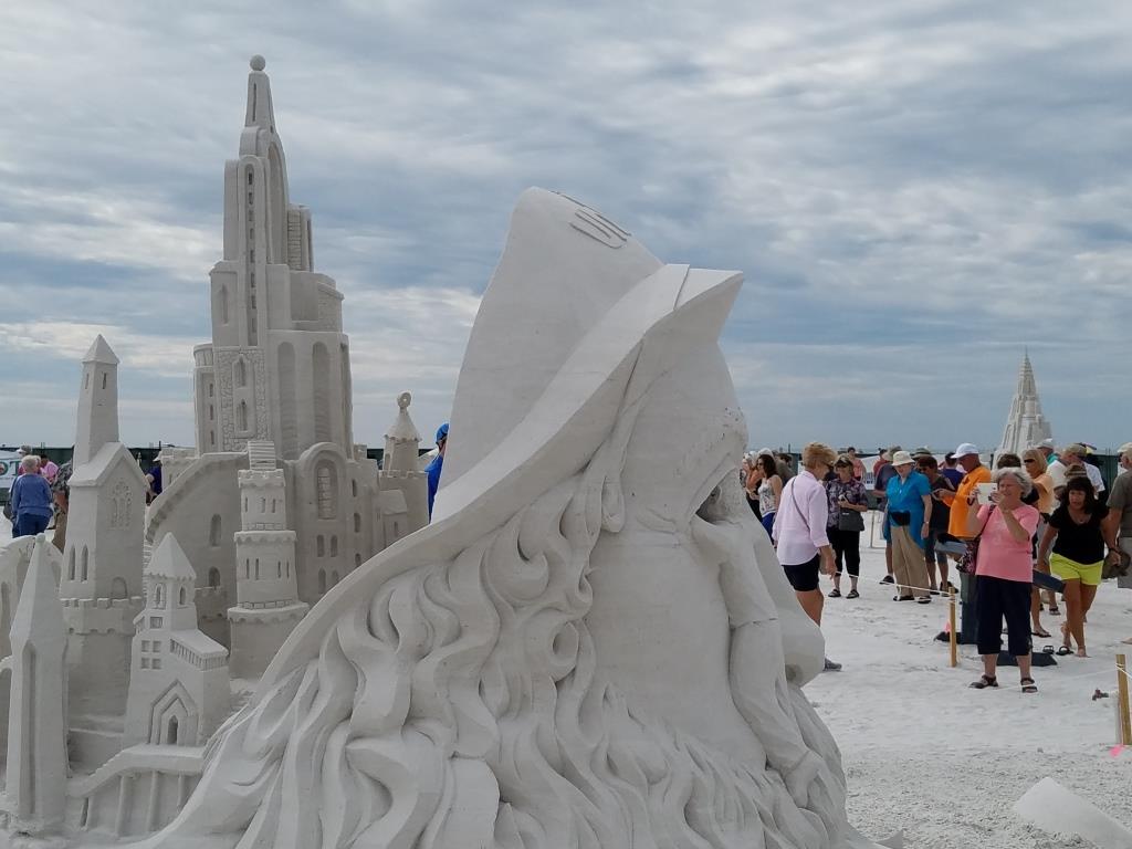
Hello all,
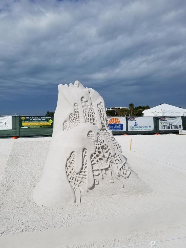
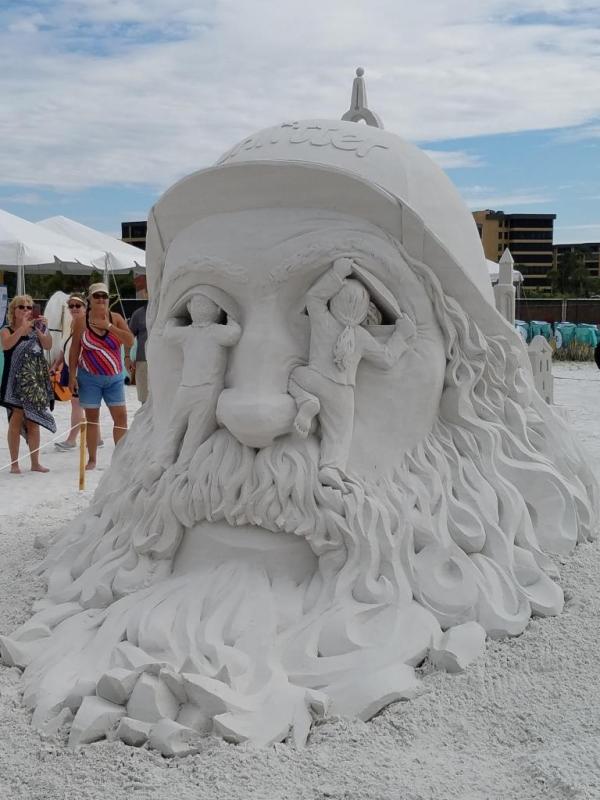
Back from vacation and finding it hard to get back into drafting up the Armenia, perhaps after the holidays. There is something from our stay in Florida that I would like to share. There was a sand sculpting competition at the beach across from our place and it's the first time we were down there when they had the event. I have to say I was truly impressed by with the amount of detail put into these sculptures. All the sculptures are 7 to 8 feet high. If you would like more information here's the web site: https://www.siestakeycrystalclassic.com/
Just a few of the dozen or so sculptures
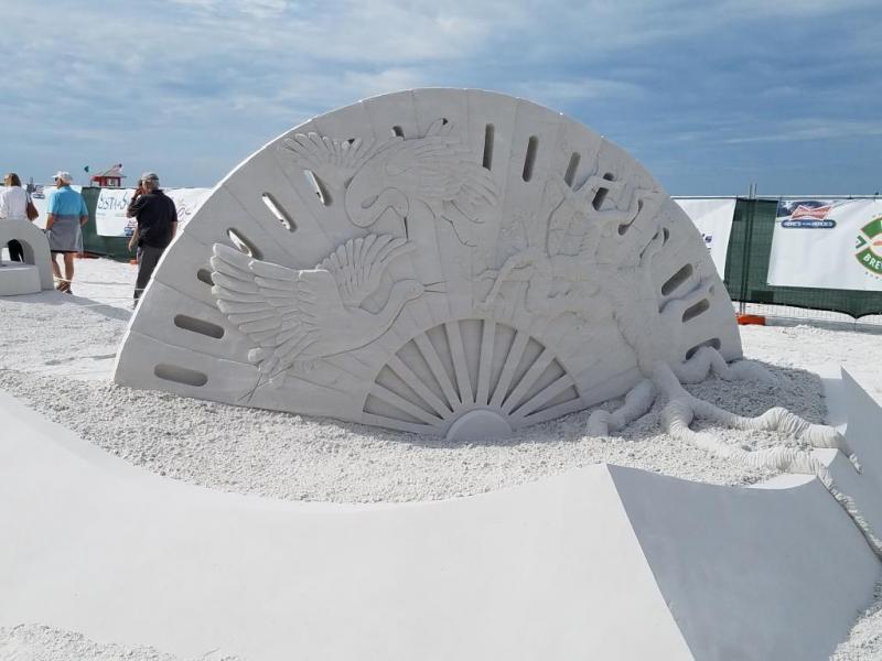

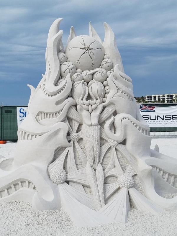

First prize winner

- Richard Griffith, hexnut, GrandpaPhil and 7 others
-
9
-
 1
1
-
-
-
It’s been a while since my last post. It just seems I’m busier now after retiring than I was when I was working full time.
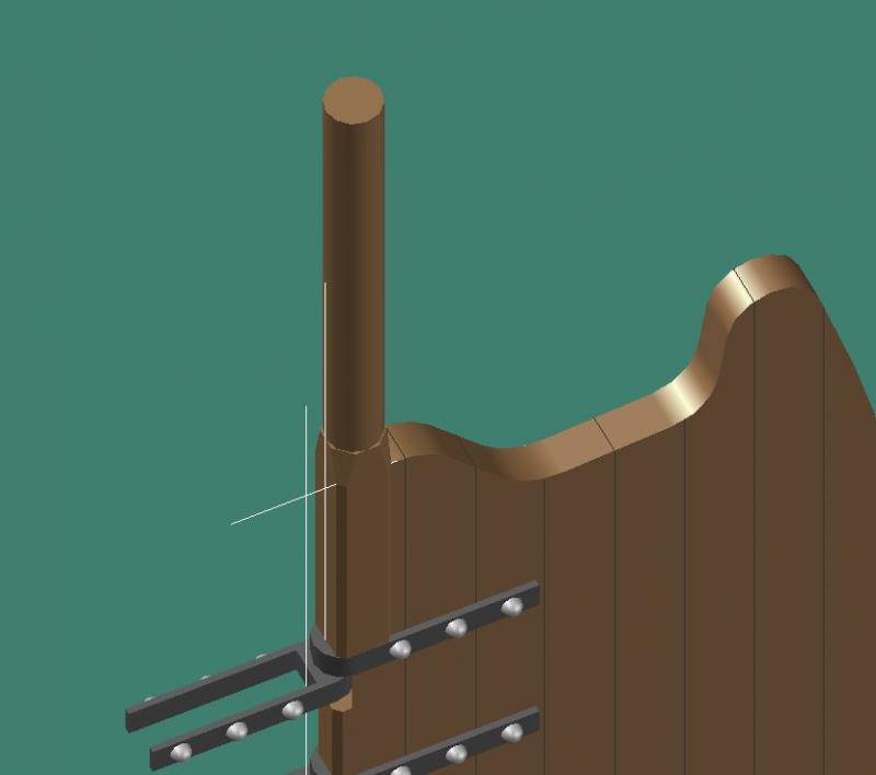
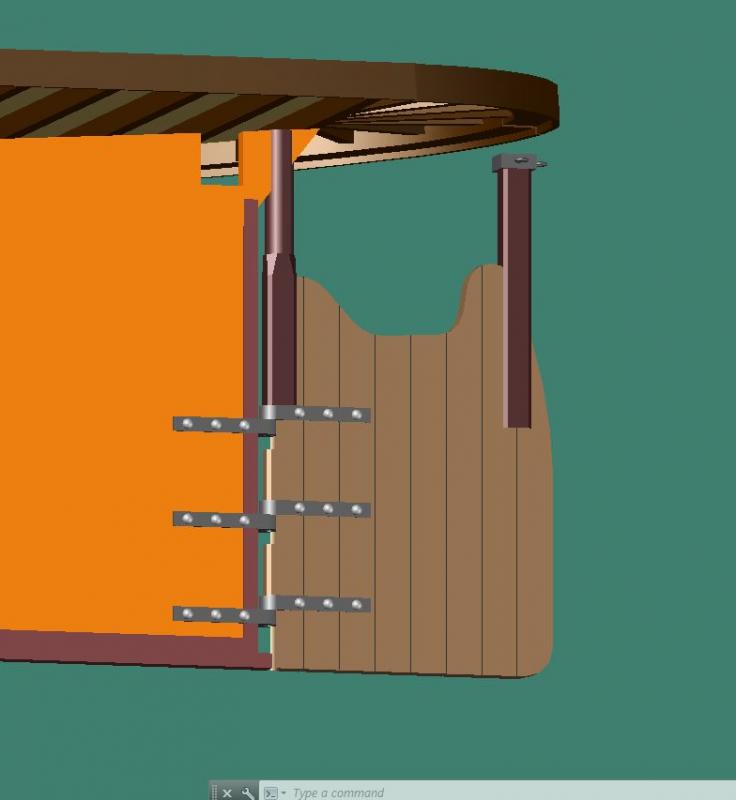
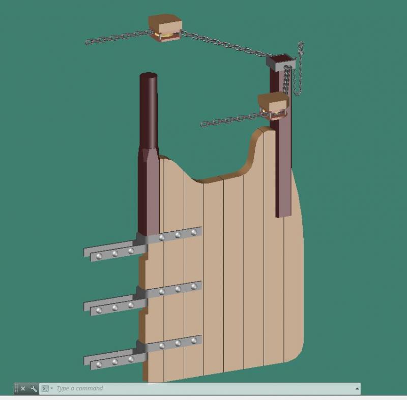
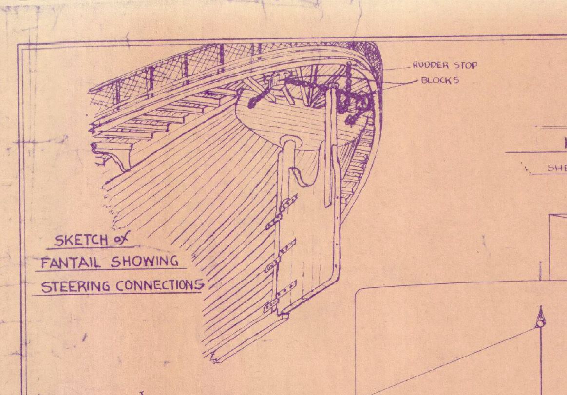
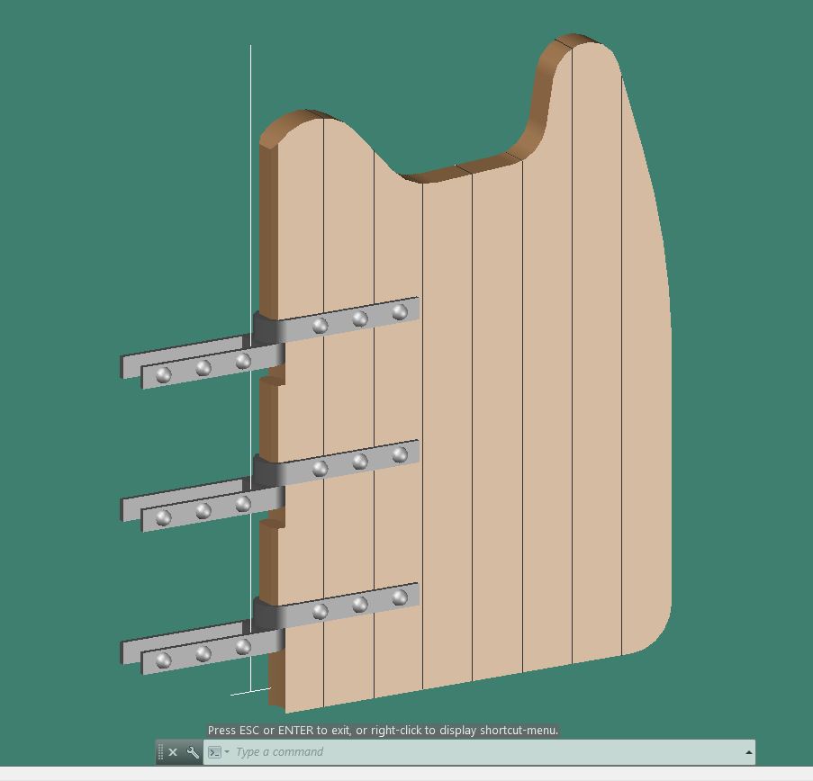
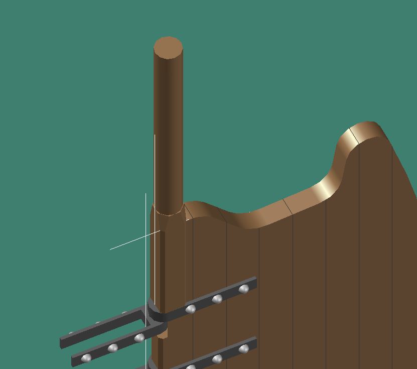
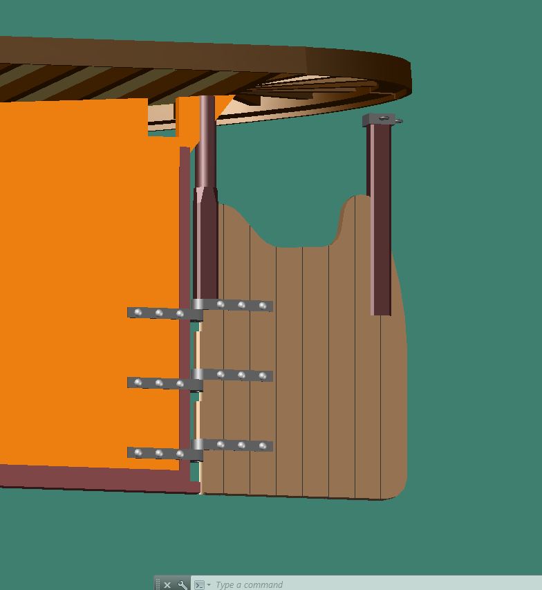
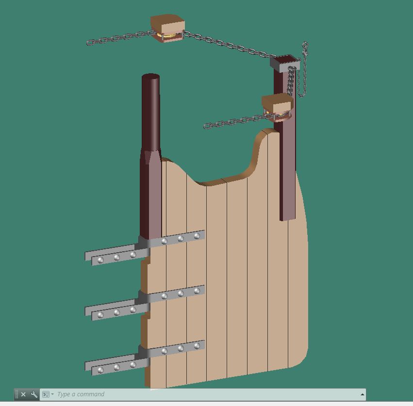
Working on the rudder to try and finish up the hull.
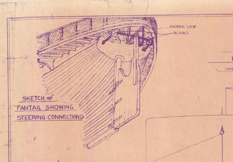
Started with the gudgeons and pintles
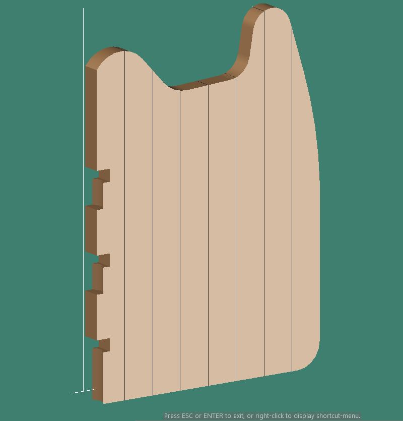
Next was the rudder itself. It appeared to be constructed of individual timbers.


Rudder post and steering post added

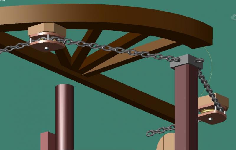
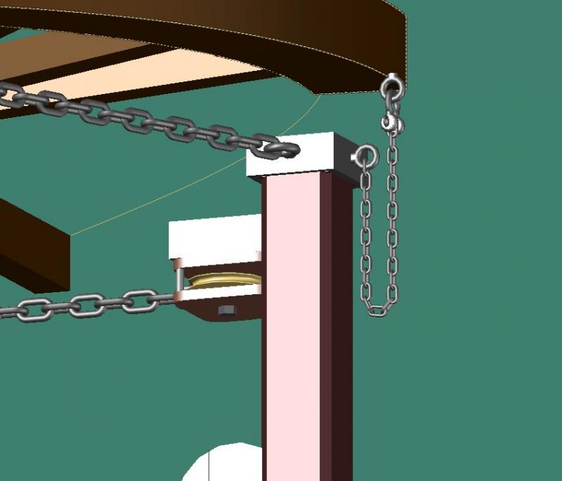
Finally the steering chains and rudder stop chains were added. Fortunately I found a ‘lisp’ program, which runs inside AutoCAD that actually draws the chain links along an established line.
-
-
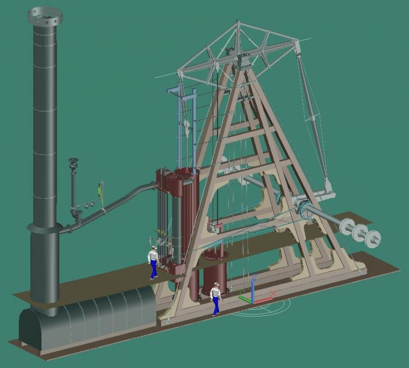
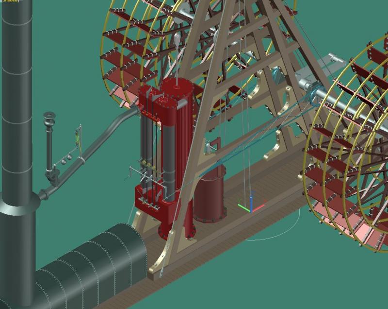
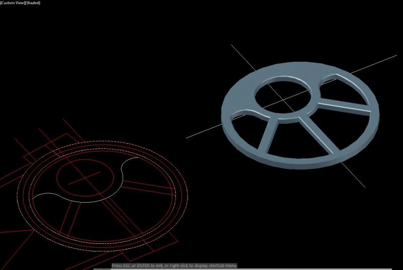
To put things into perspective I added a couple workmen to give an idea of how big these engines were. The upper figure is on the ship's main deck and the lower figure is below deck. I cannot take credit for drawing the 3D man, I borrowed them from my former place of employment. The person is roughly 6 foot tall.

-
Elijah, it's easier than it looks with cad software. First you make one, rivet or nut, then just copy it as many times as you like. If their in a circular pattern there is a command called 'Array' which will evenly distribute copies of an object in a circular pattern around a center point.
-
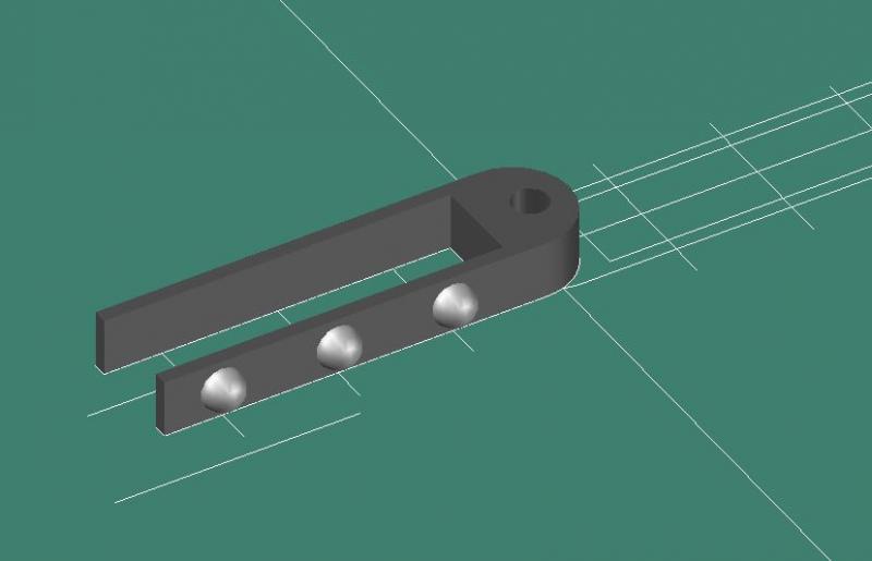
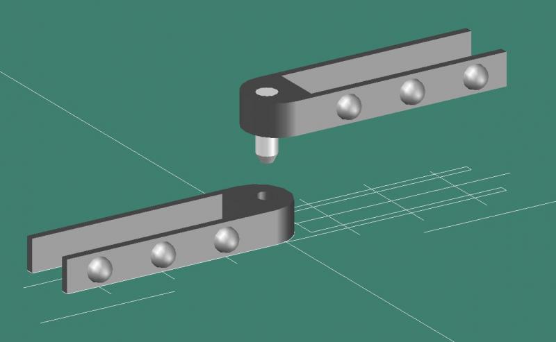
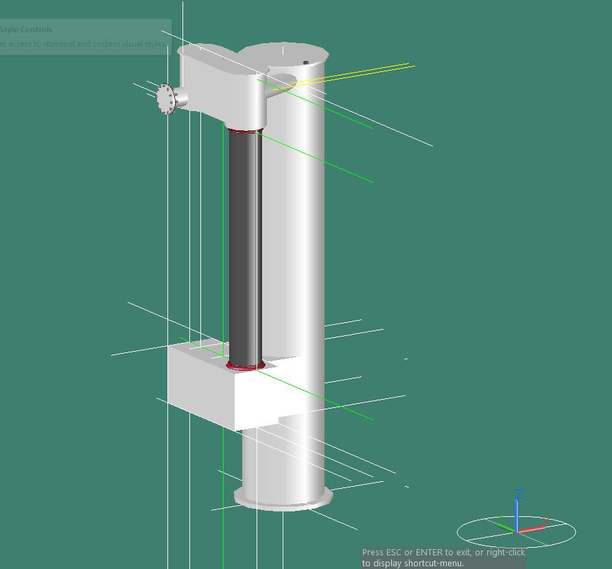
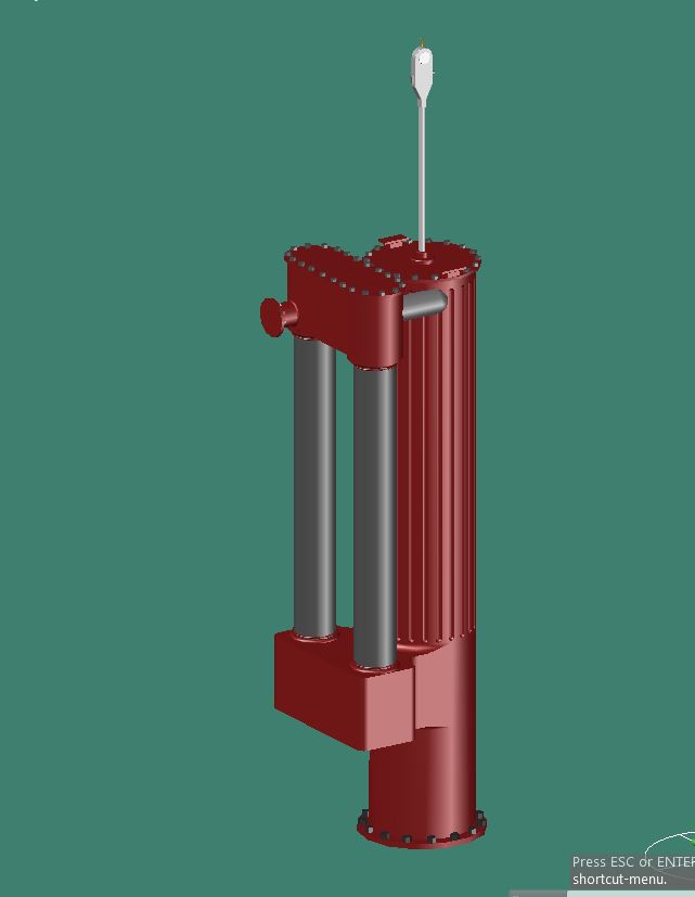
The engine is made up of a few major parts.
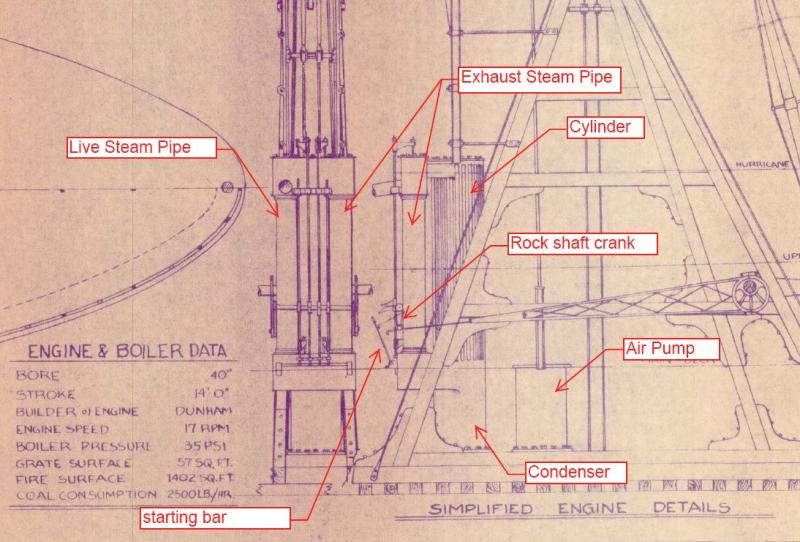
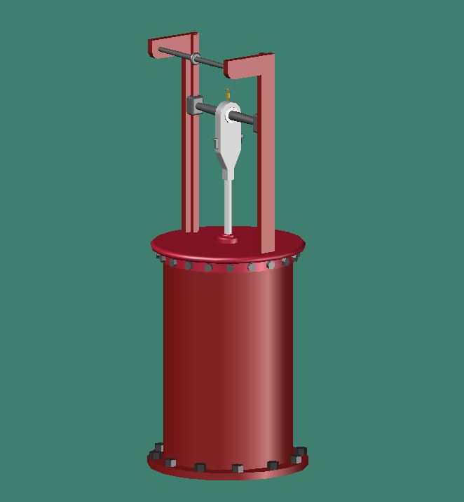
The first part that I modeled was the air pump. The air pump was connected to the condenser and was used to draw off the condensed water and steam vapor. This was fairly simple to model as a cylinder with a piston rod. The air pump was operated by the two slimmer connecting rods coming down from the walking beam at the beams quarter point.
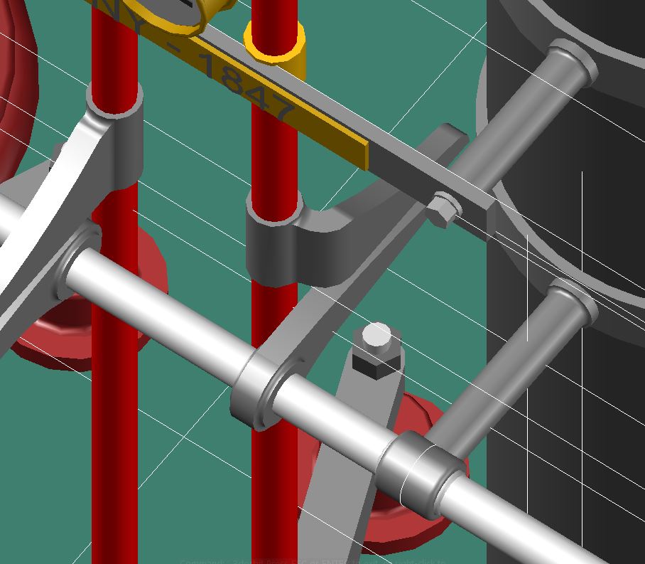
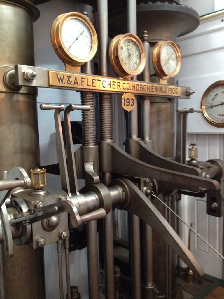
Next I started on the main engine which is comprised of the condenser, cylinder for the main piston rod and the live steam and exhaust steam pipes.
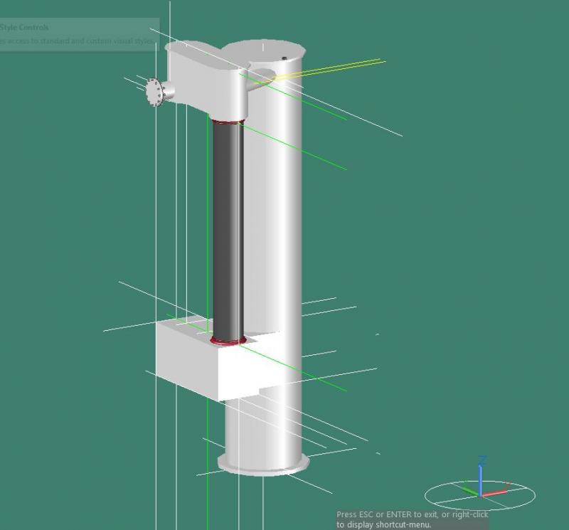

Next I modeled the valve lifters for the live steam and exhaust steam.
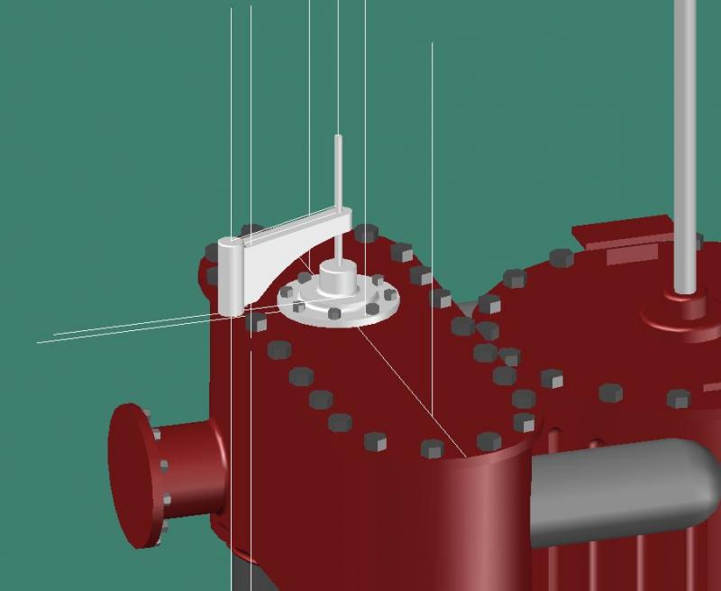
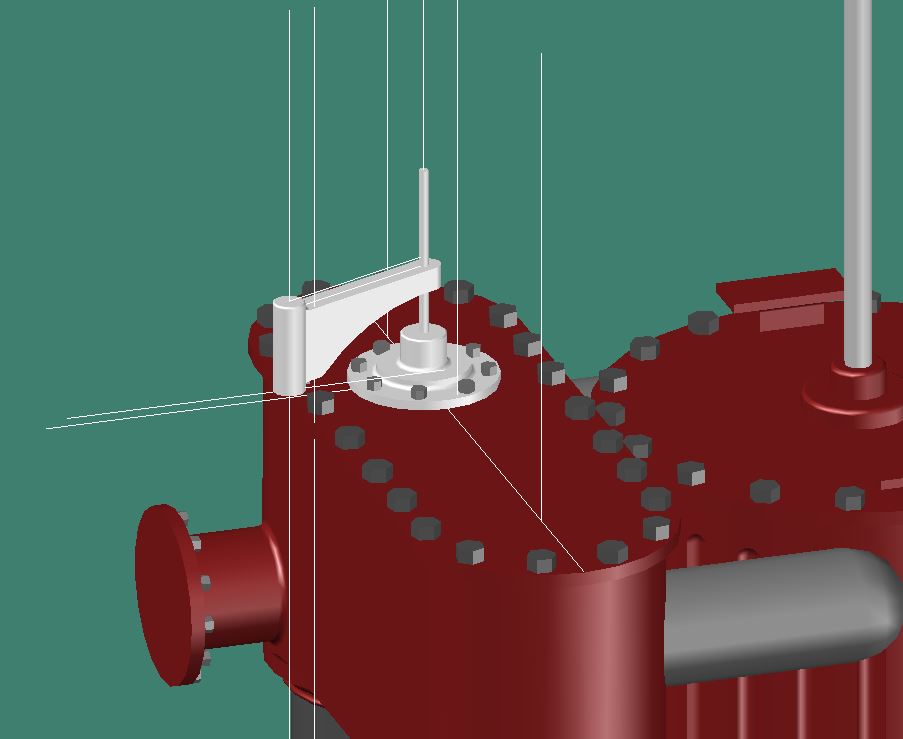
The valve actuating mechanism consisted of a set of large, curved cams called “wipers” which worked against followers called “toes” which were affixed to vertical rods going to the steam and exhaust valves at the upper and lower ends of the two cylindrical vertical steam pipes. The drawing of the engine did not clearly show how these cams were laid out but I did find a good reference. It was on goggle books called “Marine Boilers; Marine Engines; Western River Steamboats”
Even with this diagram I still ran into a little interference with the cams. It’s not clearly shown in the diagrams but I believe the outer cams must have had and offset to operate correctly.
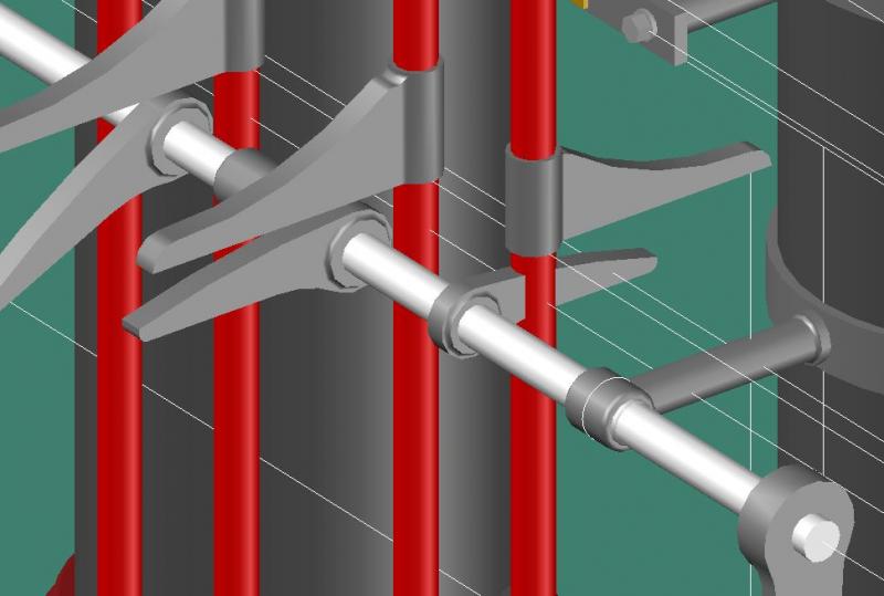
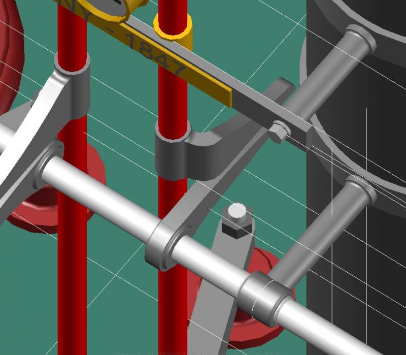
Completed valve actuating mechanism. The lower smaller cams with the starting bar was used by the engineer when first starting the engine either forward or in reverse. The rock shafts were two separate shafts supported in the center by a common bushing.
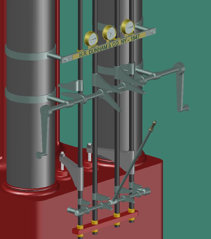
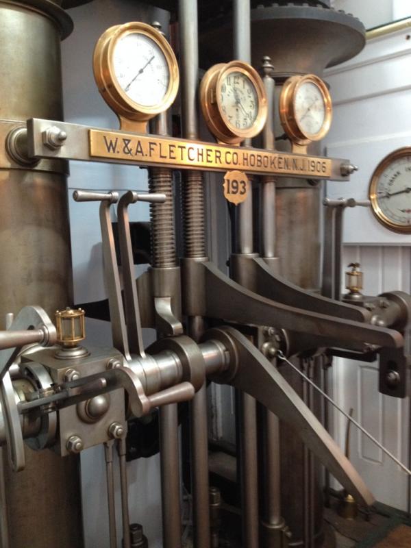
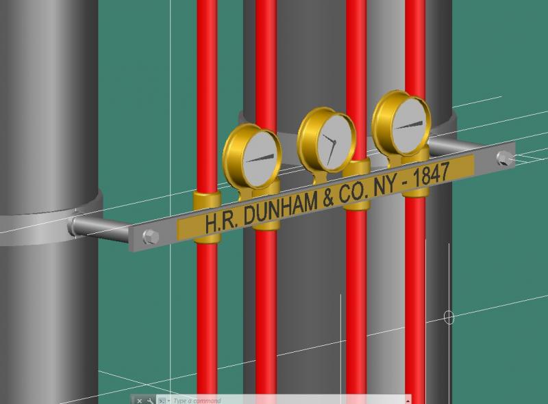
The pressure gauges and clock layout was plagiarized from the Ticonderoga.
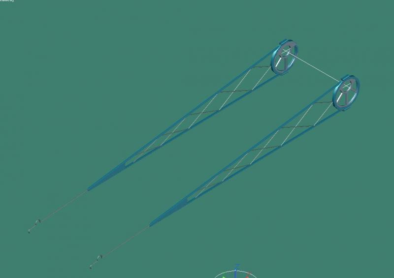
Engine, air pump with eccentrics
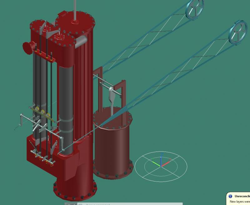
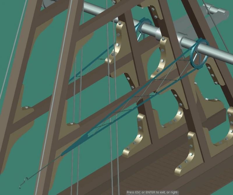
Engine in place
-
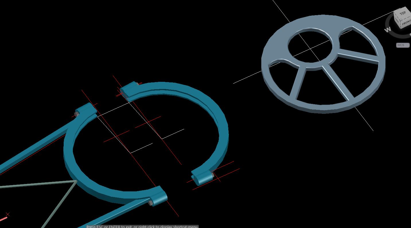
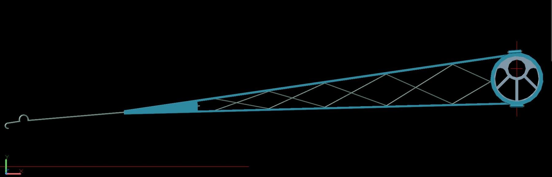
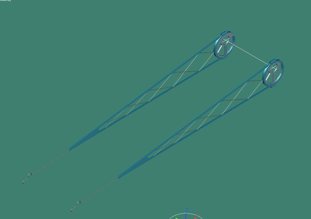
There were eccentric rods on either side of the engine that once the ship was under way would be engaged onto a rock shaft which operated the steam intake and exhaust valves (more on those to come). The eccentrics are connected to the paddle-wheel shaft and have off-centered hubs which produce a back and forth movement in the eccentric rod.
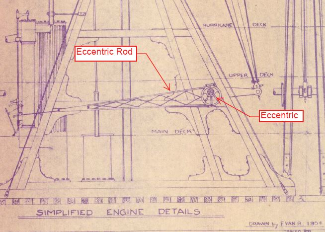
Eccentric
This is how I believe the eccentric rod mounted to the eccentric.
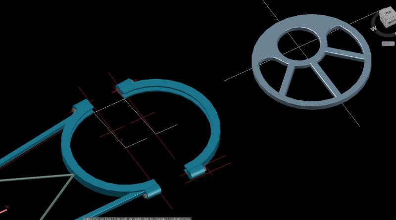

Eccentric pair
Mounted to the paddle-wheel shaft.


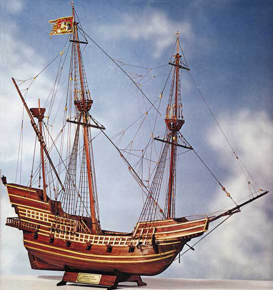


Prins Willem by _SalD_ – Corel - Scale 1:100
in - Kit build logs for subjects built from 1501 - 1750
Posted
All decks installed along with the stern upper transom.
I found and downloaded a .pdf copy of Herman Ketting's book 'Prins Willem' which appears to contain quite a bit of useful information on the construction of the ship. My only problem is that it's written in Dutch! There are some nice pictures though that might come in handy.