HOLIDAY DONATION DRIVE - SUPPORT MSW - DO YOUR PART TO KEEP THIS GREAT FORUM GOING! (Only 24 donations so far out of 49,000 members - C'mon guys!)
×

MarisStella.hr
-
Posts
479 -
Joined
-
Last visited
Content Type
Profiles
Forums
Gallery
Events
Everything posted by MarisStella.hr
-
 Hi Mike, I heve been following this build, it is really very good... Zoran
- 968 replies
-
- 4
-

-
- hahn
- oliver cromwell
- (and 1 more)
-
Hi Ed, I follow this build of Yours for some time now ... breath taking staff ... otherwise, I now designed kit for a full rigged ship (19th ct.), I have to say they are very similar, but my work will not be without planking, the frames will not be visiable ... Zoran
- 3,618 replies
-
- 3
-
-
- young america
- clipper
- (and 1 more)
-
Hi giampieroricci... I was followed this build, it is very very good that you have done... Zoran
-
Mr. DocBlake, I just have to say ... this is an excellent work ... Zoran
- 306 replies
-
- 3
-
-
- armed virginia sloop
- Patrick Henry
- (and 2 more)
-
Let's start with modelling the 'Batelina' Now it is time to introduce yourself with the frames and the keel. The time to feel the planking with the planks, strips, to shape them and to learn how the intarsia is becoming in front of your eyes, as a result of your work. This is why this little Adriatic coast boat is so important for the continuing of the modelling school. Her lines are not very complicated, there are just a few frames more than ‘Optimist’ has, but still, my opinion is that she is very pretty model when done correctly… And of course, she is still very easy to build … When opening the box of ‘Batelina’ kit you will not be very impressed, but wait to see the result of this build. I promise, you will change the opinion. The first thing you'll notice, like to the two previous kits, is a photo of the boat and a book of instructions for building ... There is a panel of plywood with the laser cut structural elements of 'Batelina' under them, right at the bottom of the box. There is also a bundle of strips for planking and some round dowels for the oars...

-
This third step in the Beginners modelling school is a little more complex and will teach you even more skills to use in future builds. Some of these being, your first introduction to a keel and bulkheads, planking a hull and constructing a grated floor. As in all builds relax, take your time and enjoy, this, the building of the Batelina. Batelina – Croatian coastal region boat A brief history and description: The names Batana and Batelina are derived from the Italian word “battere” which means to hit, this was describing the sound of the flat bottomed boat hitting the waves. Other sources claim the name derives from the ancient maritime name “batto” which was a small 14th century boat, the Anglo Saxon’s used the name “bat” then finally the English word “boat” came to be. This vessel is now found throughout the entire Croatian coastal region and has undergone several evolutionary changes. The present day small boat, about 4meters long (approx. 1:3 length-width and about 0,5m high), is now used locally as a fishing vessel, it is the result of a combination of changes taken from the Istrian Batana and the original Batelina. The kit is based on this mixture of characteristics of the Batelina and Batana. The 4 meter long Batelina is exclusively a flat bottomed boat which has a slight rise at the bow and stern. She has a flat angled stem post and a curved transom rail. Her sides are flat and flared outwards give way to a beautiful line throughout her length. On the rails are 8 bits, four aft and four at the bow also a thole pin on either side. The bow and stern are enclosed giving way to storage and the floor is grated, her single thwart (seat) is located the middle of the boat. Her source of propulsion is two oars with no sails.

- 221 replies
-
- 10
-
-
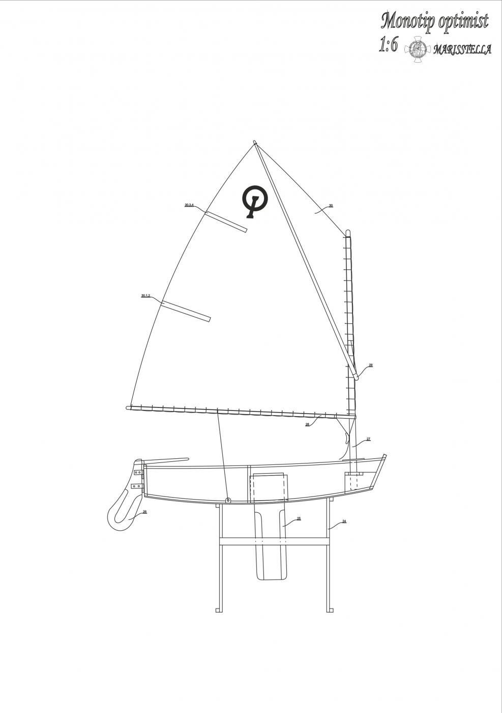
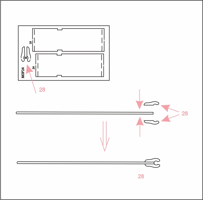
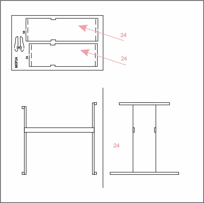
Secure the sail evenly with ties along the luff to the mast 27 and along the foot to the boom 28, pulled down tightly to the ratchet block 23.1 by a vang (kicker). Extend the sprit 29 through a loop at the seal’s peak. Its bottom rests in the eye of a short string which hangs along the front edge of the mast. Raising and lowering the sprit 29 and adjusting the boom vang do some adaptation of sail, trimming to a range You want to. After you set the mast and the sail, fix the model to the stand 24 and Your model is finished.

-
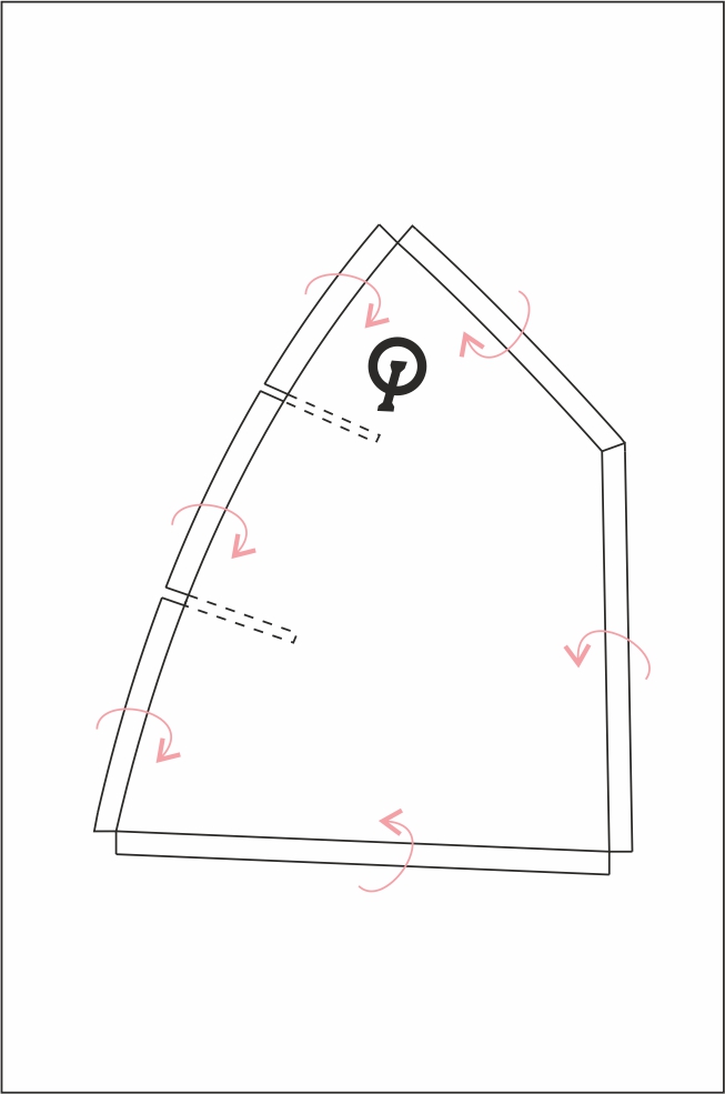
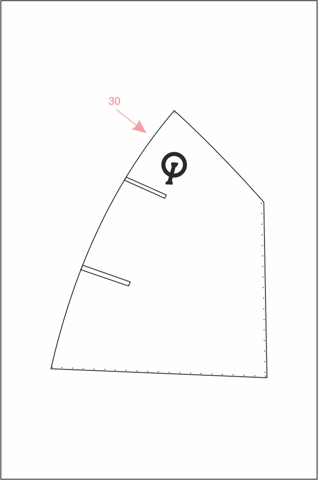
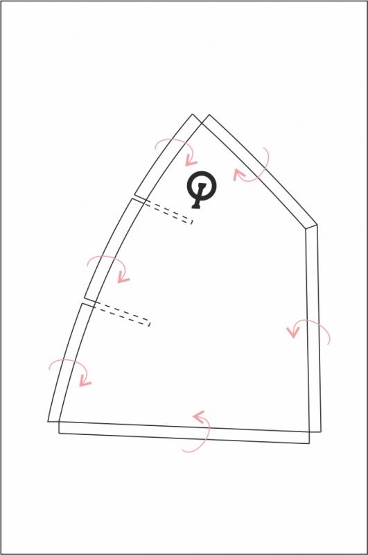
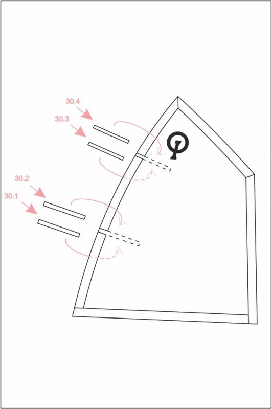
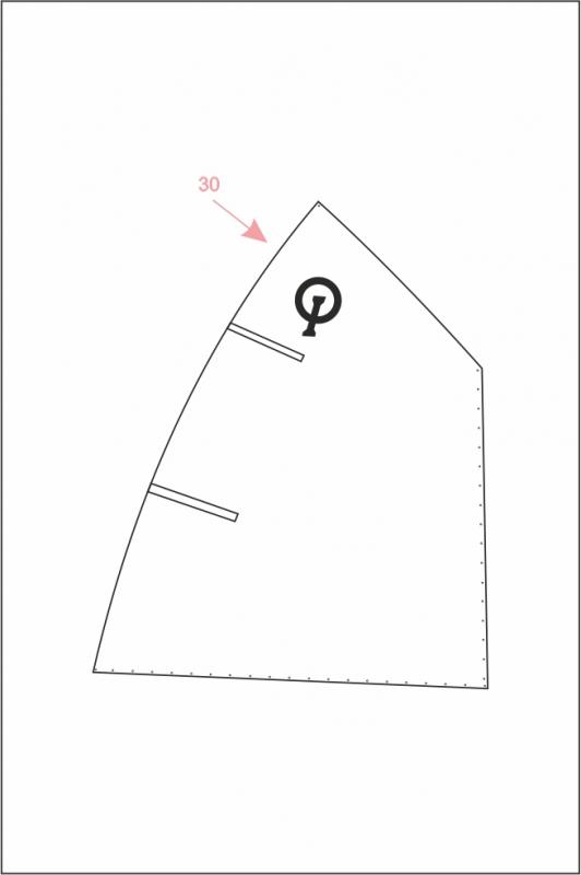
Construct the sail 30, tracing it on the fabric. Then put a thin coat of resin glue on its exterior edge on the fabric, to prevent it from tearing. Cut it, following the interior line. You can also construct it if you do it 5 mm outside the edge line, and than hem it. Don’t forget to leave spaces in the hem for two battens 30.1 and 30.3. They stiffen the leech.Glue the battens 30.1, 30.2, 30.3 and 30.4. The ‘Optimist’ has the synthetic sail, so that this sail should be plasticized. To do this, the simplest is to use the color for the metal. Choose the color You want and apply it to the sail. Apply a thin layer of paint several times to the sail. You should wait until the paint dries well between the coatings. However, this sail will be hard, but it can be shaped.
-
… Just as a reminder that You need to remember, this goes for all models of ships: Models of ships should be painted so it does not shine. Use acrylic paint and an acrylic colorless matt varnish. Here's the procedure: first polish a model with sandpaper. Then coated a mixture of 40% linseed oil and 60% thinner and immediately wipe with a cloth. When dry, paint it as desired and let everything dry completely. Re-sand and polish as needed and paint everything one more time. When everything is dry again, spray with colorless matte varnish on two occasions, between which is enough to wait twenty minutes. So You will get perfect colored model. Rarely it happens that, after painting with colorless matte varnish, on wood the appearance of tiny fibers that protrude and look ugly. If this happens, just re-polish the element and re-spray matte varnish. Fiber will disappear. Construct the mast 27, boom 28 and the sprit 29. Use the dowels assembled to the mounting set. Grind them, cut them and polish them. There is a cleat to the lower part of the mast 27. The cleat is placed on the 1 mm veneer motherboard. Separate it and glue it to the place, to the mast 27. Color and varnish those elements as you wish.
-
Construct the model's stand 24 using finished elements from the 4 mm plywood motherboard and 10x3mm laths, as well as 5x5mm laths. Use the draft. Polish the stand 24 using fine abrasive paper, color it and varnish according to Your wishes.
-
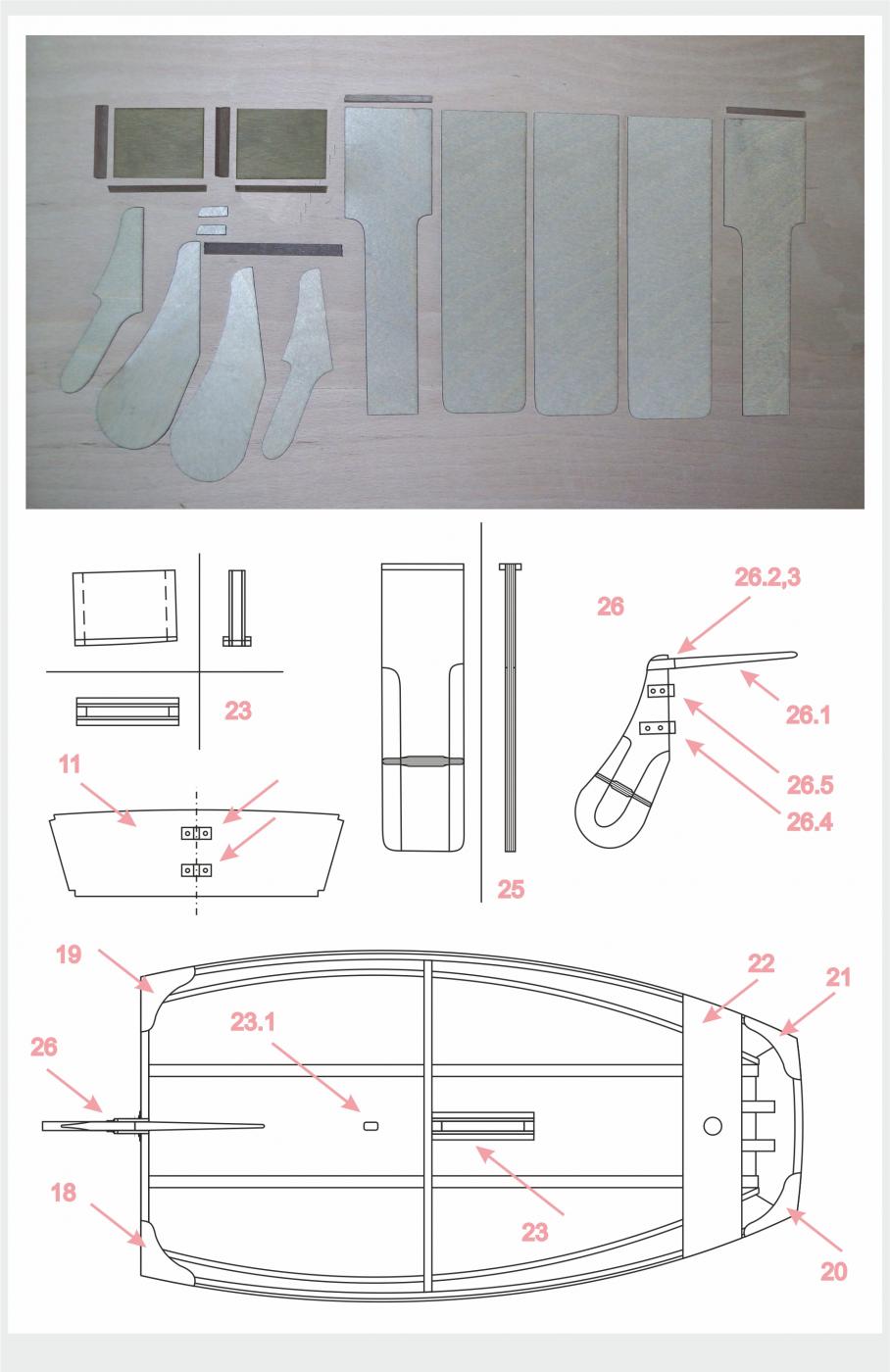
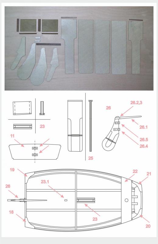
Construct the daggerboardcase 23 from two 1mm veneer panels, as well as 5x5mm and 3x3 mm laths. You should grind the bottom of this element so it fits uniformly on bottom 2, around the opening. Glue it to its place. Polish everything using fine abrasive paper, color it and varnish according to Your wishes. There is the ratchet block 23.1 on the 4 mm plywood motherboard. Glue it to its place, to the bottom 2. Construct the daggerboard 25 using five elements from the 1 mm veneer motherboard and 3x3mm laths. Glue them together and grind them to get the proper shape of the daggerboard 25. Its cross section is shown in the drawing. You need to achieve exactly this shape by grinding. Grind the sides of the daggerboard 25, so the daggerboard 25 can easily pass through the daggerboardcase 23 after coloring. Polish everything using fine abrasive paper, color it and varnish according to Your wishes. Construct the rudder 26 using four elements from the 1 mm veneer motherboard. Glue them together and grind them to get the proper shape of the rudder 26. Its cross section is shown in the drawing. You need to achieve exactly this shape by grinding. Construct the tiller 26.1 (5x5mm round laths) and glue it to the rudder 26 using the tiller holders 26.2 and 26.3. Fix the rudder hinges 4 mm wide to the rudder 26. They are fitting assembled to the mounting set. Polish everything using fine abrasive paper, color it and varnish according to Your wishes. Fix the rudder hinges 4 mm wide to the transom 11 as it is shown to the draft.
-
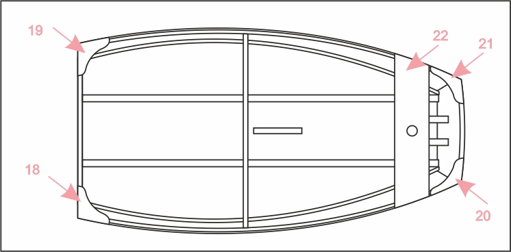
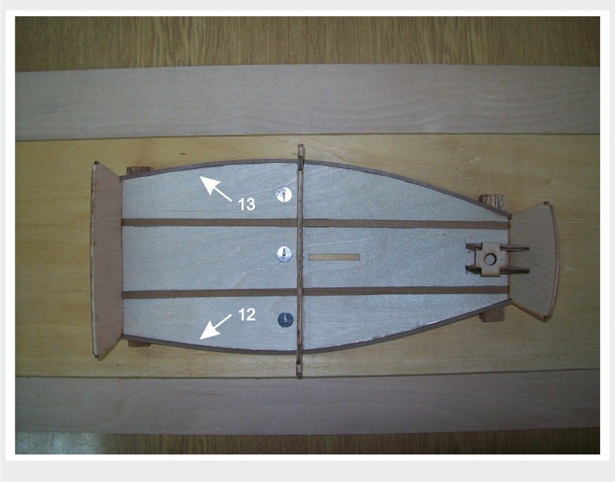
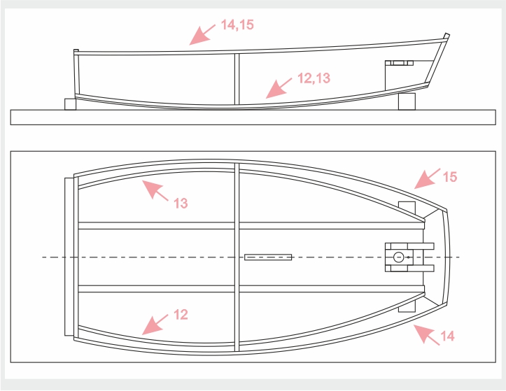
Glue elements 18, 19, 20 and 21. … They are placed on the veneer board 1mm thick ... … Please note that they are slightly larger than the sides of the hull ... This is so that it is easier to set them up ... They need to be sanded after being glued to the corners of the hull. It is the best to use sandpaper on a wooden block … The thwart 22 need to be set now. It is slightly bent upward. Separate it from the veneer motherboard and glue it at its place… work its edges with a sandpaper on a wooden block … Polish everything using fine abrasive paper, color it and varnish according to Your wishes. We recommended the white color for the whole model.
-
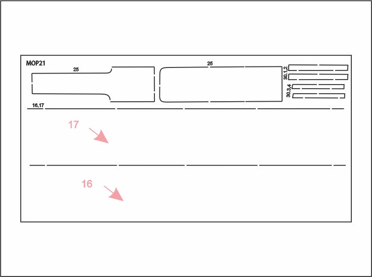
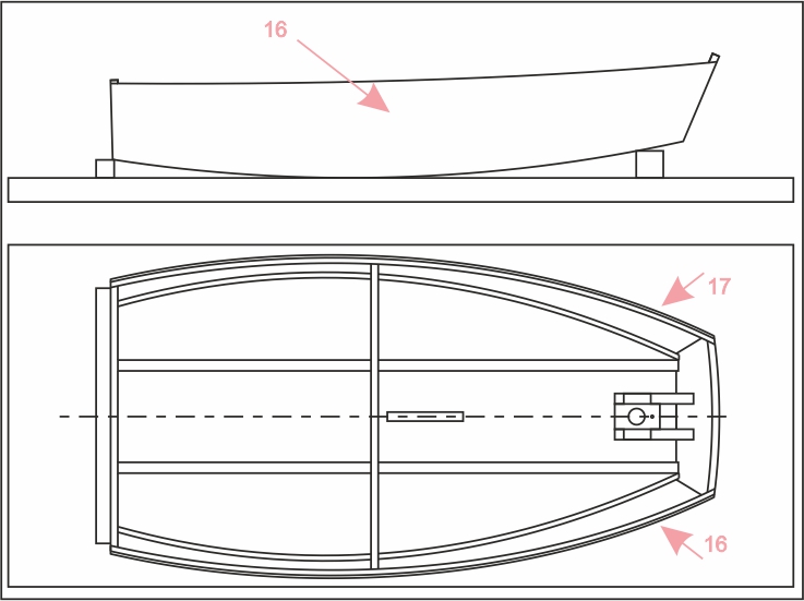
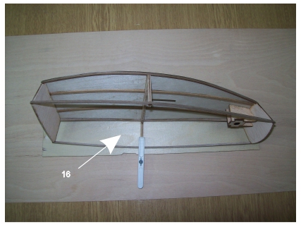
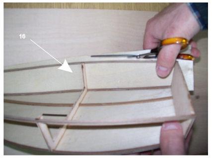
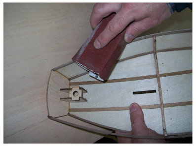
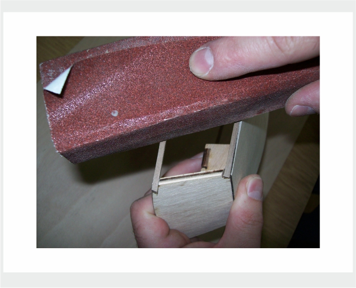
Then, when You are convinced that the planking will lie perfectly on the sides of the frame 10, transom 11 and bow 7, and on the laths 12, 13, 14 and 15, leaving no gaps, let approach to the planking setting ... … The planking is placed on the veneer board 1mm thick ... It is carried out in two parts, 16 and 17 ... One part is to be placed to the left side of the hull and the other part is to be placed to the right side of the hull ... …Separate the planking 16 and 17 from the veneer motherboard … … It is important to note here that the planking are larger than the sides of the construction ... This is so that it is easier to set them up ... You will cut them after their setting (gluing) to the sides of the construction … … Approach to their setting : First check how this would be looking like ... … Glue the planking to the central frame 10 of the construction. Tighten it with a plastic clamp ... When the glue is dry, glue the planking to the transom 11 and to the bow 7 ... When the glue is dry, trim the front part ( to the bow) and the rear part (to the stern) of the planking so it fits correctly to the construction ... The following photos show this part of work: … When the planking is pasted to the construction of the hull, at the both sides of the 'Optimist', it is necessary to trim the planking properly : - The bottom of the planking should be cut at the level of the flat bottom 2. - The top of the planking should be cut at the level of the laths 14 and 15 at the top. - The rear of the planking should be cut at the level of the transom 11. - The front of the planking should be cut at the level of the bow 7. ... to do this, use the scissors at the first, then a scalpel, and then adjust the edges of the planking with a sandpaper on a wooden block … … Well, the hull of the 'Optimist' is finished, but the 'Optimist' is not finished yet …

-
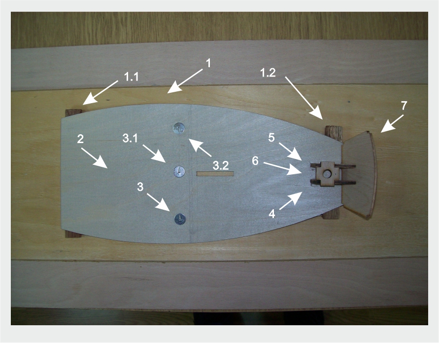
... And now it's time to separate the construction from the base 1 ... You should only pull out the pins 3, 3.1 and 3.2 carefully... The holes that are left will be filled with wood putty later... Once you checked the construction and its curves that you have done, check out the famous 'fairing', adjusting the edges of the frames once again... Sand those edges a little bit more if necessary ... use the sanding paper on a wooden block for this purpose…
-
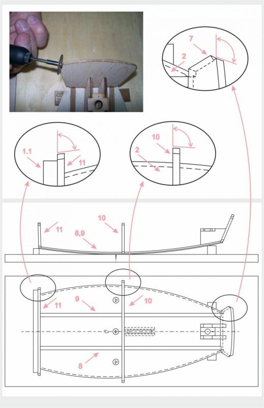
Adjust the side groves for the laths 12, 13, 14 and 15 to the frame 10, transom 11 and bow 7. Use some grinding tools. … When the frame 10, transom 11 and bow 7 are in place, and when the adhesive has dried, the most important step in the forming of the hull is following: grinding of the external walls of those elements ... Their out sides should be formed so that the planking flows in a nice flowing curve of the hull shape. When it is done right, it also gives the more gluing area to strengthen the planking… I will try to take out a basic rule once again: … grind sides of the frame 10, transom 11 and bow 7, in order to lean the planking uniformly, and to prevent the creation of holes on planking and bottom joints. First, the edge surface of the frame 10, transom 11 and bow 7 askew by grinding them at the bow and stern to allow proper fit of the planking as shown in the plan. Askew the side edges of bow 7. Its rear surface, the one facing the stern, leave untouched. The side edges of transom 11 askew so that its front surfaces, the one facing the bow, leave untouched. … This should be correct if the frame construction is made properly ... A hand-held power tool for engraving is the best to use … Insert and glue the laths : All the laths (strips) in the ship modeling which should be bent should be first soaked in water, so that their fibers become soft and flexible, and easier to bend the laths (strips), and this does not break. Glue the laths 12 and 13 (3x3mm) to the edges of the bottom 2, into the groves on the frame 10, transom 11 and bow 7. Make sure that those lower laths 12 and 13 should protrude a little bit over the edge of bottom 2. Glue the laths 14 and 15 (3x3mm) into the groves on the top of the frame 10, transom 11 and bow 7. The laths 12, 13, 14 and 15 will form the hull shape and will close the construction of the Optimist.

-
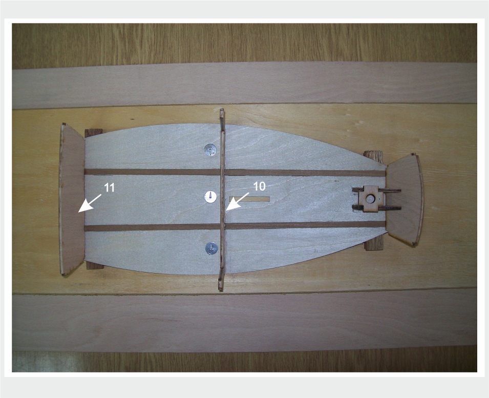
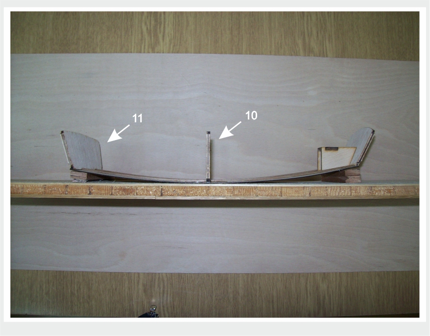
Work the transom 11, specially its bottom, so that bottom 2 can lie at the right angle, as shown in the drawing attached. Glue the frame 10 on its place, to the bottom 2, across the laths 8 and 9 as well as the transom 11.

-
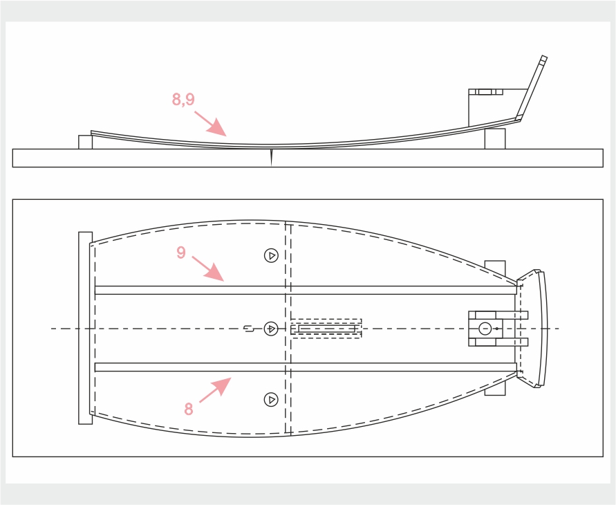
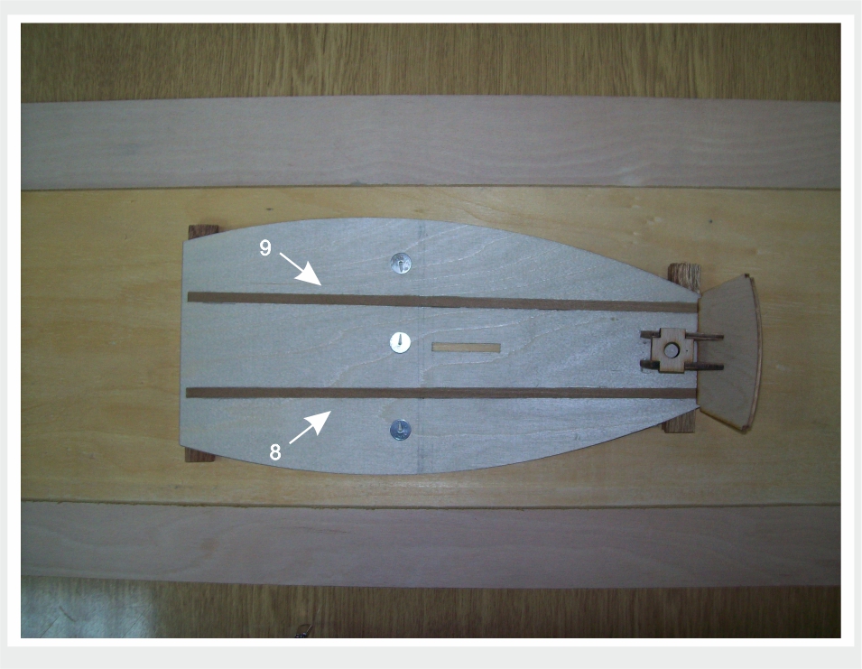
Measure and cut laths 8 and 9 (6x2mm). Make sure they lean properly. Separate frame10 and clean its edges. Insert the laths into grooves in the bottom of the frame 10. Put some fast drying glue in the middle of the lower side of the laths 8 and 9 and press them to the bottom 2 on previously marked places, so that frame 10 lies properly between the edges of the bottom 2. When everything is dry, remove frame 10, because it only served as a mould for gluing the laths.
-
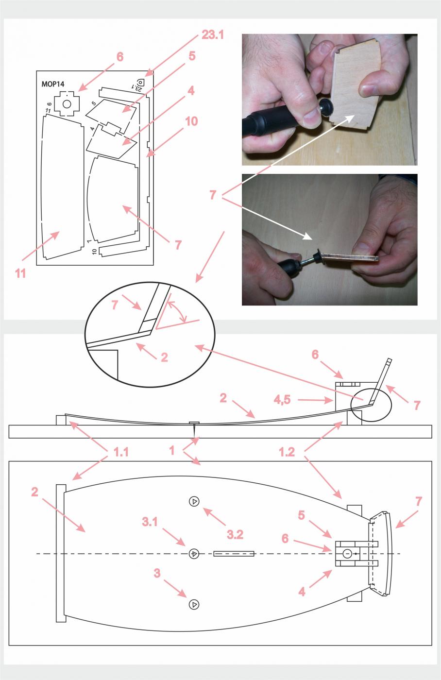
Separate elements 4, 5, 6 and 7 from the plywood motherboard. Grind the edges to remove blacken burned areas. We recommend the use of electric engravers. Very occasionally, the laser does not cut off elements of the plywood in its entirety. If this happens just saw with jig saw element to the end and remove it from the motherboard. Glue the elements 4, 5 and 6 together. They make the mast step. Now grind the bottom of the element 7 diagonally, in order to lean uniformly on bottom 2. It is the bow 7. Its interior side should lie on frontal surfaces of elements 4 and 5, as shown in the drawing attached. Glue them like that. Then, the composed block of the elements 4, 5, 6 and7 glue to the bottom 2. This block must rest on the bottom 2 precisely. Use the drawing all the time.

-
So, as I said before, when you access the construction of some model, the first thing you need to do is to open the plan and instructions for building... You should look at the plan more times and then read the instructions ... It is good to look briefly first, and then several times with the understanding ... Only when you are sure you understand each step to create a model, you can approach its building... When you do so, you can start... Here , you will need a wooden board first ... This board , the bearing plate 1 , is heavy and it is not included in this kit … It should be rectangular, slightly larger than the bottom of the vessel is. Its most appropriate dimensions would be 2cmx43,5cmx16,cm. On the bearing plate 1 you should fix supports 1.1 and 1.2 (1.1 made from 10x10 mm lath, 14cm long, and 1.2 made from 15x15 mm lath, 8cm long. Those laths are included in the kit, as well as everything else needed for the construction of this scale model ) … This is shown on the drawing attached, look at the top of the sheet. This is a kind of mold that you will need later to bend the bottom of the vessel properly ... Otherwise, whichever model you build, a work stand is required ... Each model requires a unique, characteristic work stand... It greatly facilitates the work and significantly raises the precision of model making … Here is the next step : … separate the bottom 2 of the Optimist from the mother board. It is made of 1 mm veneer. The elements are cut off by a laser. Only small uncut parts hold them to the mother board. Those uncut pieces you need to cut with a sharp knife and separate the elements from the board... It's time for the bottom 2 shaping ... Now, it is necessary to set the bottom 2 to the prepared mold 1 ... The back edge of the bottom 2 should be placed to the 1.1 lath. The front part of the bottom 2 should be placed to the 1.2 lath. ... NOTE: no one part of the Optimist should not be glued to any part of the mold 1 , not in any case, not at any spot ... Press the middle of the flat bottom 2 to the board of the mold 1 and knock it down to it with the pins 3, 3.1 and 3.2 … The spots where the pins should be set are precisely marked on the draft… The following image shows this :


-
Ed, brilliant thing ... no mold could do this !!! ... perfect blackening . Zoran
- 3,618 replies
-
- 2
-
-
- young america
- clipper
- (and 1 more)
-
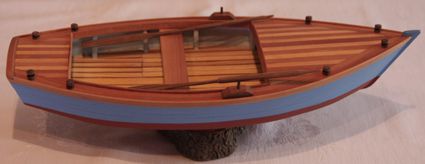
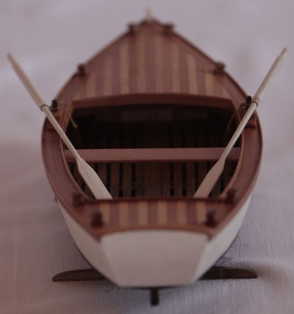
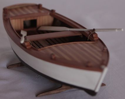
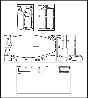
Modeling the 'Optimist' The hull with very simple lines, just a few frames, having not a keel, flat bottom, each side made of a single piece of plank, simple sail and a rudder makes the ‘Optimist’ to be a very suitable for the next step ... This is a second very easy to build, perfect example to explain certain basic operations that are constantly occurring in ship modelling ... When you open the box of this second very simple kit, the first thing you'll notice is a photo of the dinghy and a book of instructions for building. The draft contains two sheets of paper ... There is a panel of plywood with the laser cut structural elements of the 'Optimist' under them... At the bottom of the box, there are two sheets of 1mm thick veneer. There is a bundle of several strips and round dowels ...
-
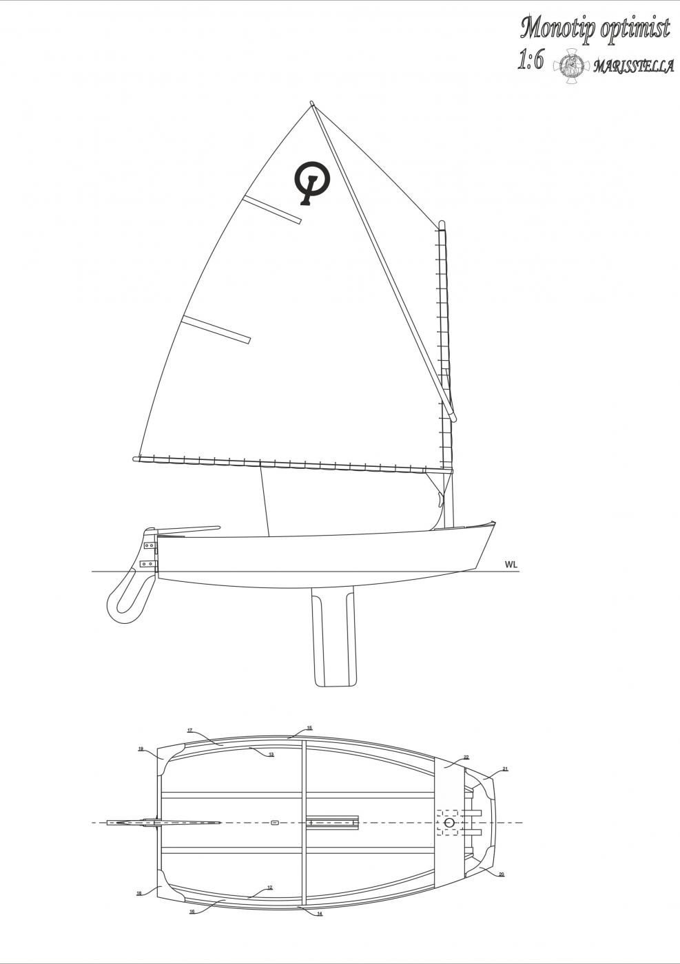
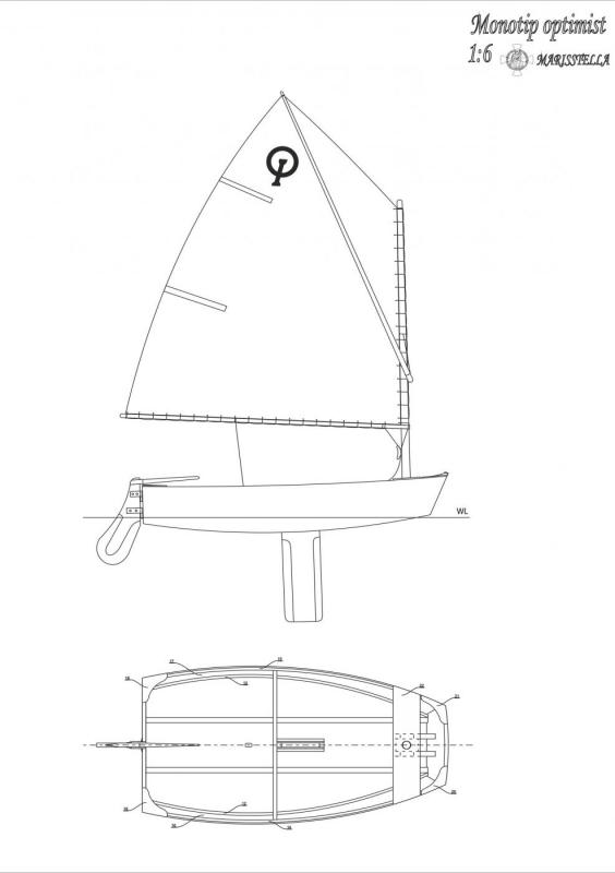
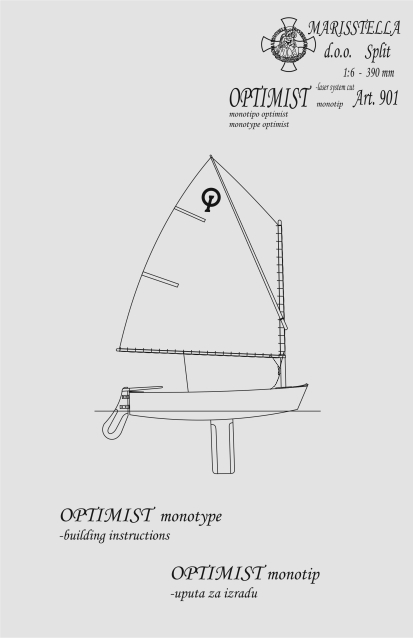
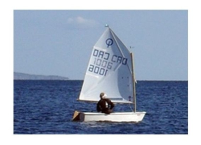
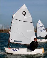
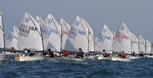
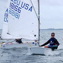
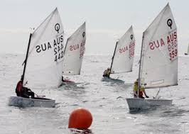
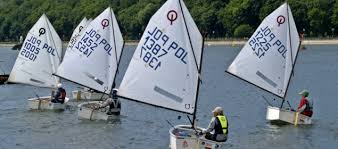
And now something completely American ... The ‘ Monotype Optimist’ Brief history of the 'Optimist' There is nothing new to say about the Optimist, except things that have already been said and written at many sources. All I can do is to repeat the facts already known... This is a small, single-handed dinghy with a sail intended to be used by children under the age of 16. The Optimist is usually made of fiberglass these days, but wood is still used to build them. This is the one of the most popular sailing dinghies in the world. There are over then 150,000 boats officially registered with the class. There are many more built but never registered. The Optimist is recognized as an International Class by the International Sailing Federation. Clark Mills, American, designed the first Optimist in 1947 at the request of the Clearwater Florida Optimist service club. He was following a proposal by Major Clifford McKay to offer low-cost sailing for young people. A simple pram he designed could be built from three sheets of plywood. Clark Mills donated the plan to the Optimists. The design was slightly modified and introduced to Europe by the Dane, Axel Damgaard, and spread outwards across Europe, starting from Scandinavia. This design was standardized in 1960 and became a strict One-Design in 1995. The Optimist is present in over than 120 countries and it is one of only two yachts approved by the International Sailing Federation exclusively for sailors under 16. The structure of the 'Optimist' The Optimist has a shallow-draught flat-bottomed (pram) hull, originally formed primarily from five pieces of plywood. Just in front of a bulkhead, which is placed almost at a half of the boat, is the daggerboardcase. Right behind it on the centerline of the hull floor are attached a pulley and ratchetblock. These anchor the rope on the boom directly above. There is a thwart at the bow to support the mast which passes through a hole in its centre to the mast step mounted on the centre line of the boat, under it. The rope used for securing a boat is usually tied around the mast step. The rudder and daggerboard could be made from plywood or a composite of foam, glass fibre, and epoxy. The Optimist has the single sail and it is sprit-rigged. The sail has two battens stiffen the leech. It is secured evenly with ties along the luff to the mast and along the foot to the boom, pulled down tightly by a vang (kicker). There is the light slim third spar, the sprit, which extends through a loop at the seal’s peak. Its bottom rests in the eye of a short string which hangs along the front edge of the mast. Raising and lowering the sprit and adjusting the boom vang allow for adaptation of sail trim to a range of wind conditions. Similarly, the Optimist has a small string outhaul on the end of the boom. It is usually correct to tighten the boom vang, outhaul, and sprit in heavy winds and loosen them in light winds. As well as this, huge adjustments can be made to sail shape, due to all of the ties running along the mast and boom. The spars are made of aluminium or wood. There is a monograph-style "IO" insignia (after IODA - the International Optimist Dinghy Association) on the sail and it is a registered trade-mark and may only be used under licence from the International Optimist Association. Optimists also have a national sail number using the Olympic abbreviation of their country and a sequential numbers. e.g. USA for United States of America. In recent years over 3,000 boats a year have been produced by around 30 builders worldwide.
-
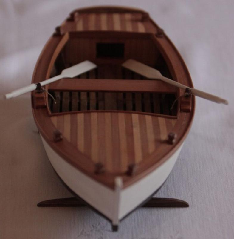
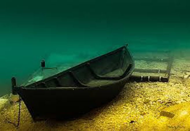
… It is not enough to assemble the model. The cream comes on the cake ... This step is so important that it must be mastered from the very beginning : A model should be painted. And it is not just like that. Each model must be painted exactly the same as the original vessel was painted in the moment when the vessel had just been completed, when she came out of the shipyard or workshop. The new 'Trupa' has always been tarred… from inside and outside… So the model needs to be painted matt black … Here is the golden rule of colouring of all models : Models of ships should be painted so it does not shine. Use acrylic paint and an acrylic colourless matt varnish. Here's the procedure: first polish a model with sandpaper. Then coated a mixture of 40% linseed oil and 60% thinner and immediately wipe with a cloth. When dry, paint it as desired and let everything dry completely. Re-sand and polish as needed and paint everything one more time. When everything is dry again, spray with colourless matte varnish on two occasions, between which is enough to wait twenty minutes. So you will get perfect coloured model. Rarely it happens that, after painting with colourless matte varnish, on wood the appearance of tiny fibers that protrude and look ugly. If this happens, just re-polish the element and re-spray matte varnish. Fiber will disappear. In the end, to get ‘Trupa’ exactly like the original is you could put a chain on the bow. So here she is, if you have done well, your model should look like the original at this beautiful photo ... ... And I'm going to prepare material for the next step of the ship modelling… Prepare yourself for a rudder and sail ...
-
The last thing to do is the pedestal. To complete it use the elements 13, 13.1, 13.2 and the plates with the inscription ‘Trupa’. Push the stretcher 13 through the openings in the side walls 13.1 and 13.2 and glue it. Glue the plates with the inscription to the stretcher 13 and the pedestal is formed… … And finally, as a reward for all our efforts, ‘Trupa’ is made up with all of her parts ... But she is not finished yet ...

-
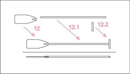
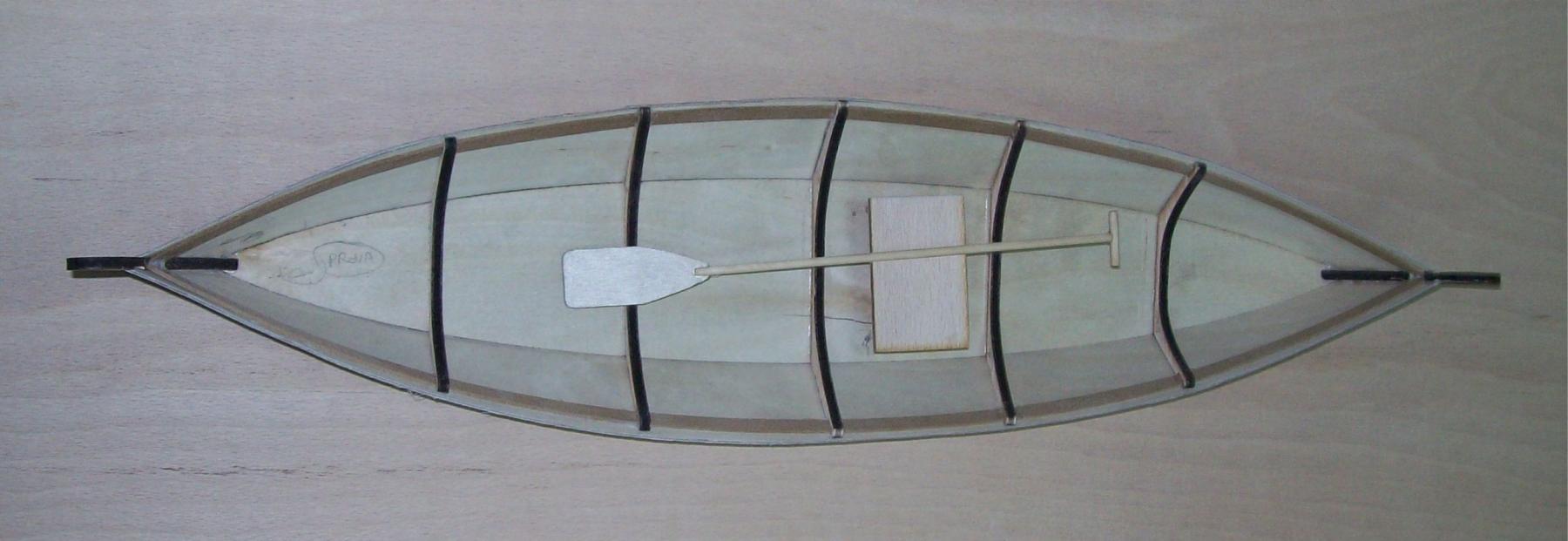
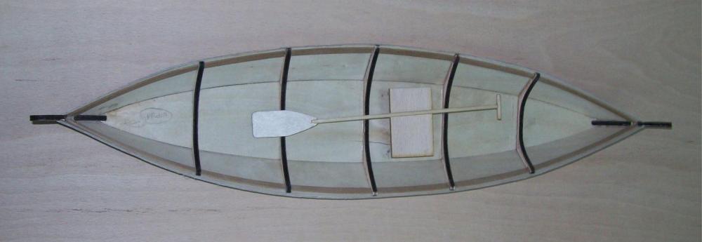
Make the paddle using elements 12, 12.1 and 12.2. The element 12 is the blade of the peddle and it is placed on the plate of 1mm veneer. The shaft 12.1 and the grip 12.2 are to be made out of the round strip ( out of a dowel) . The dowel’s diameter is 3 mm. Shape the throat of the peddle and glue all together.