

kirill4
-
Posts
903 -
Joined
-
Last visited
Content Type
Profiles
Forums
Gallery
Events
Posts posted by kirill4
-
-
Good day Dear Bill,
Please consider my remarks as... just remarks of outsider vewer 😄... not like demands that You must do it in this way only and no step aside allowed ! In no way I expected my remarks will "...adding the stress and anxiety over wanting to make sure every line, block and piece or of the authentic size, color, and scale....."
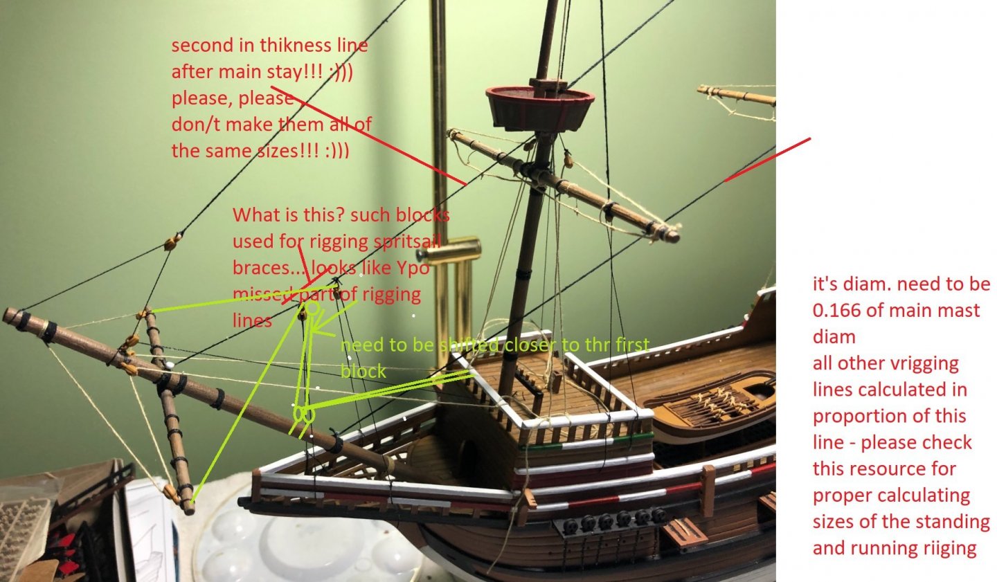
Funny thing, that from my point of vew , this part of assembling model which consists of collecting information and searching how things should looks like and how they work, this is the relaxing enjoyment😁😁Rigging diagrams from the kit which You posted, looks quite accurate and correct in general,
however some things shown probably wrong or excessively simplified and schematic for such big scale...
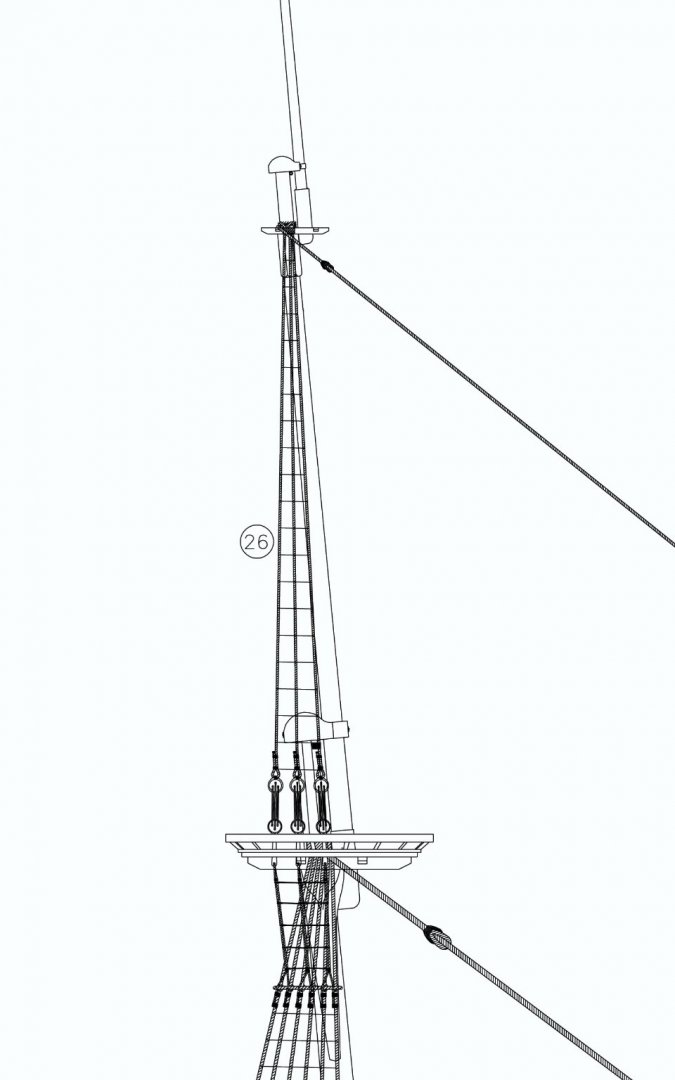
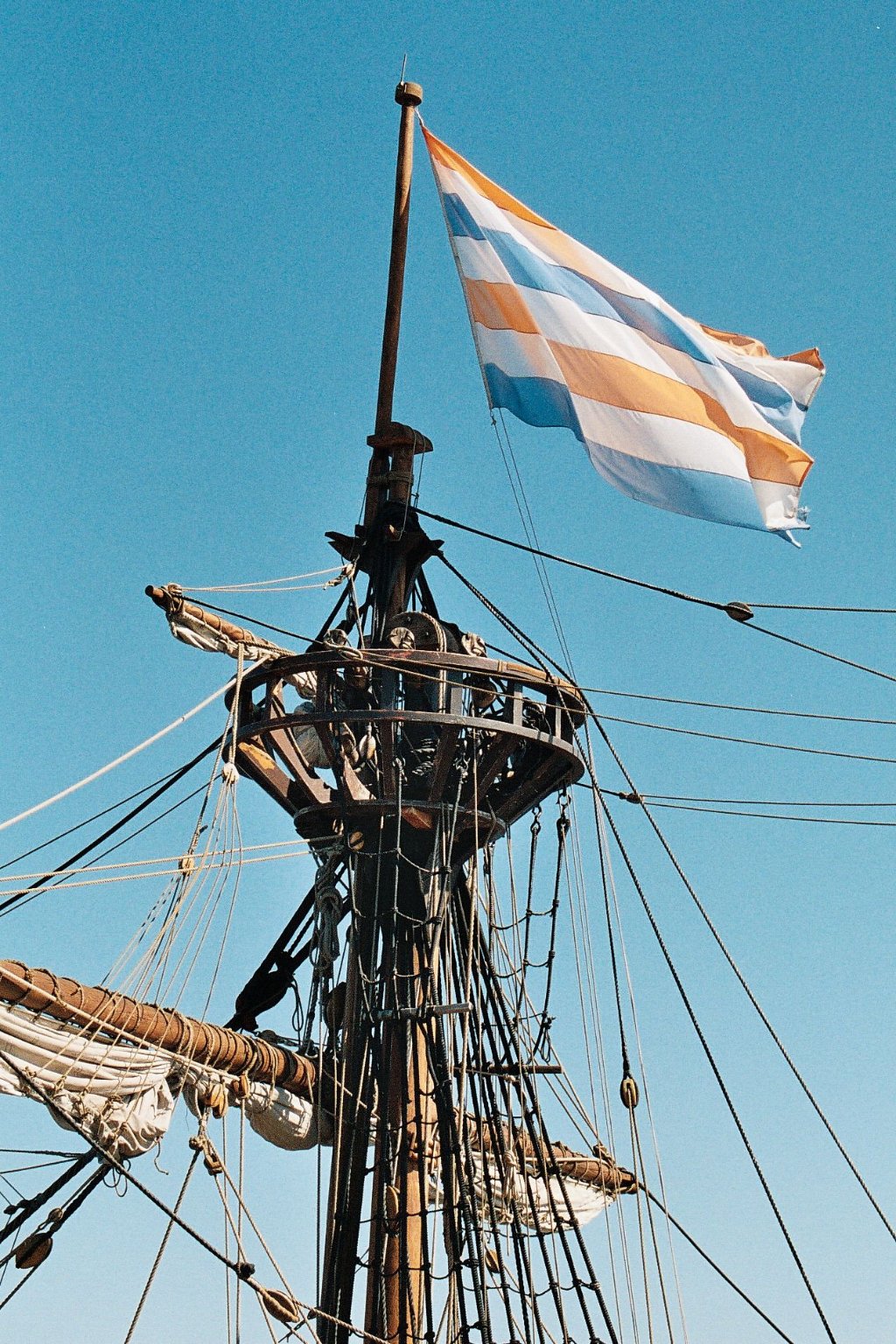
please check this knights placed near the bases of the masts - they supposed for main sails or mizzen sail tie halliyards but not for the main topsail braces as shown in the kit
coming back to this lines n6 and n7 as per kit rigging manual , there is no scence at all to arrange them by this way , this is enigma for me, why kit shows it like this? Looks like kit designer missed something in this part of rigging :)))
-
Bosco72,
I didn't reach this stage on my model yet \
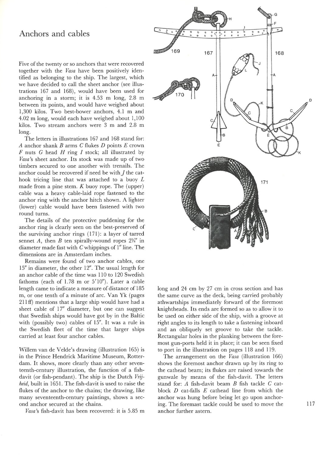
I saw anchor hitch knot need to be made ...and planned to try to do it as shown in Mondfeld or Landstrem "Vasa" book.
May be will do it on this week...
-
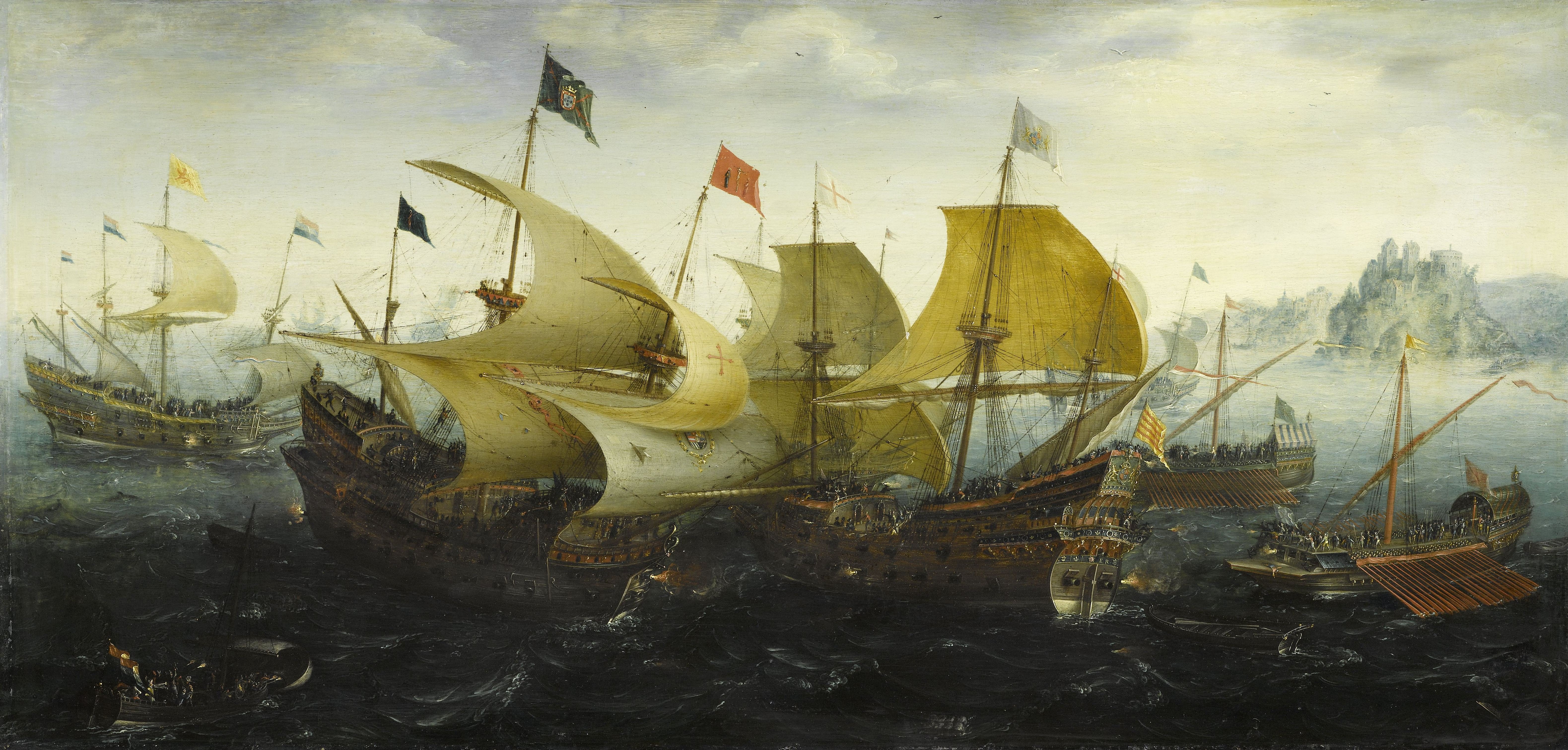
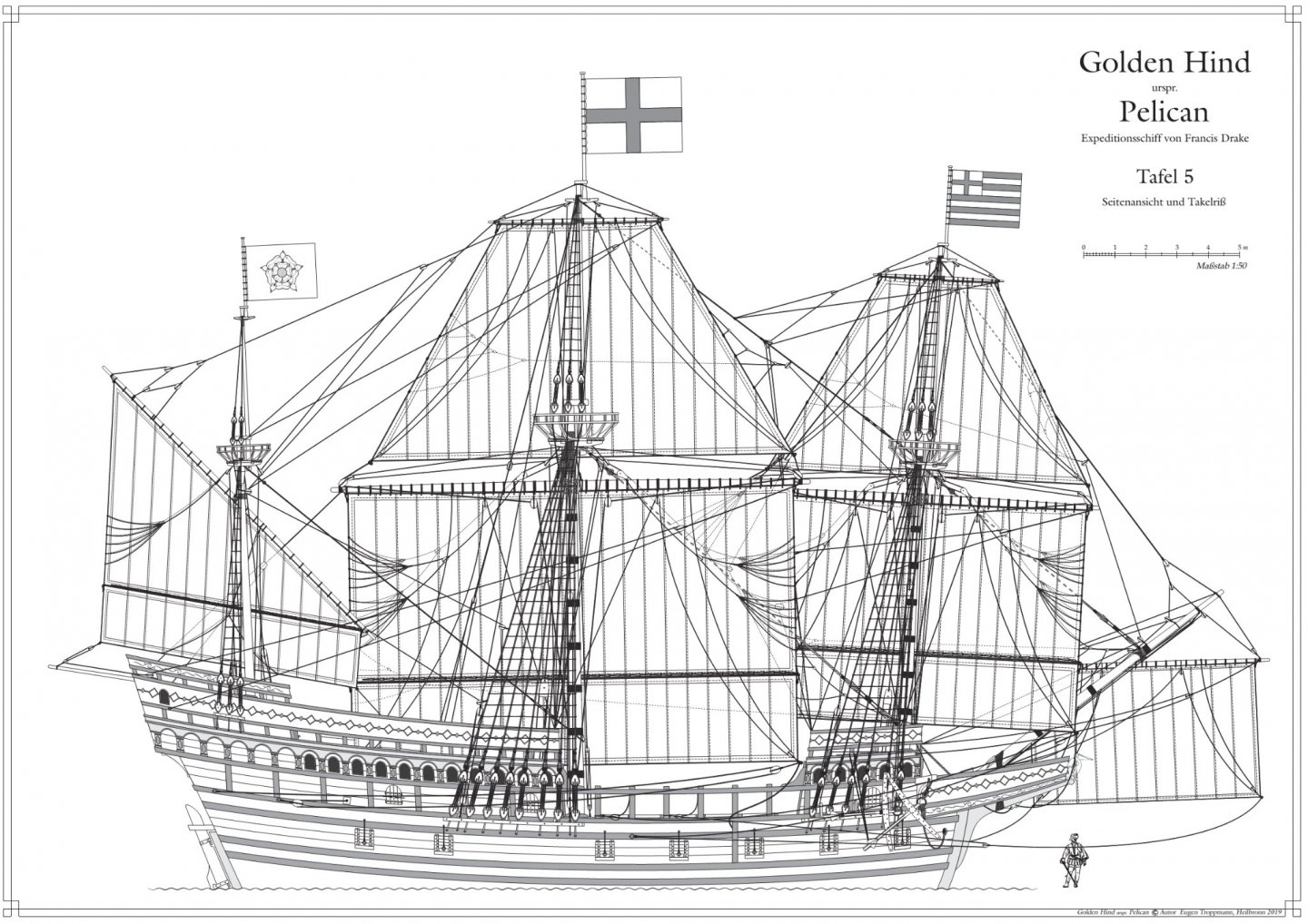
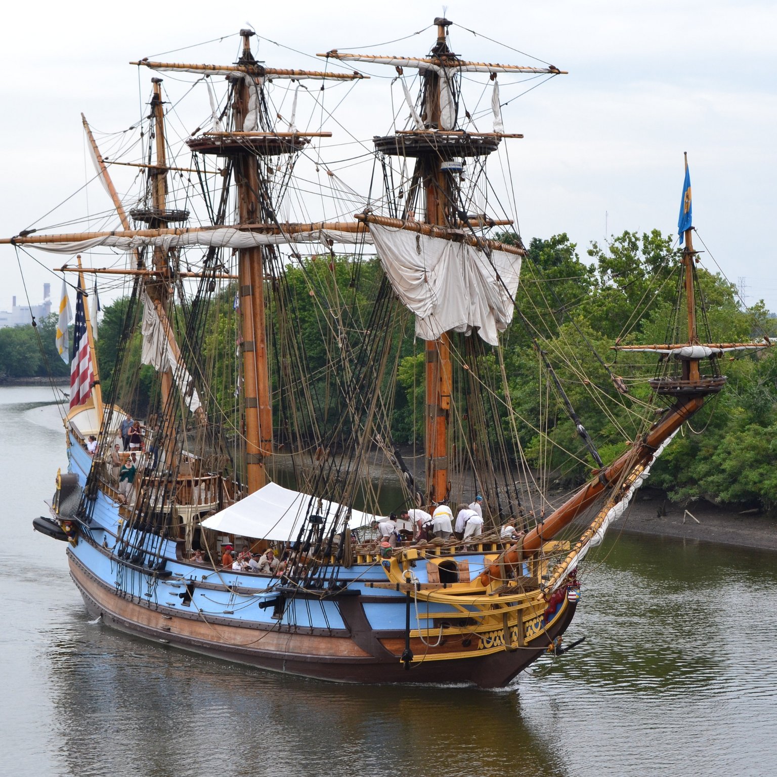
replica rigging plan
.thumb.jpg.4acb9ebf5f79b19115760e206249f6b6.jpg)
- Larry Cowden and Tomasz B
-
 2
2
-
-
Tomasz,
By my opinion, there are a few ways to make rigging:
*to build exactly as suggested in your kit
*to build as existing relica
*to build as suggested in the books Andrson and Mondfeld- regarding proper rigging arrangements but maybe not exactly as your model kit suggested
*to build as Mayflower II rigging
*to build as Aker siggested| developed by eugen.t in his reconstruction
to avoid repeating all the same information again
please check recently posted drawings in nearby treads of GH and Mayflower buildings as we discussed rigging variants just a few days ago...
from my point of vew there is most interesting rigging plan for GH made by eugen.t based on Aker reconstruction...
-
-
Good day ,
Dear Tomasz,
Your model looks very nice... however I would reccomend to read this GREAT book written world famous author(in ship model making and history receach) which will help You a lot!
https://cloud.mail.ru/public/JU7C/bVhk9VrXn
There You will find description od every rigging line You will need to arrange on Your galleon model ...
All The Best!!!
Kirill
- Larry Cowden and Tomasz B
-
2
-
Dear Bill,
I'm very sorry :)))
but have some thoughts...after watching Your model fotos...
May be there is sence, to avoid making mistakes, to spend approx 20 min. to read Anderson book?
https://cloud.mail.ru/public/JU7C/bVhk9VrXn
https://cloud.mail.ru/public/Aua2/rJZNnLbhj
https://cloud.mail.ru/public/3Wmx/iJuDBUo6v
https://cloud.mail.ru/public/MpaE/CZdnEmv6e
just read relevant page about each of rigging lines before You will start making any rigging lines.?
.. of couse if it is matter /important for You, to make rigging more or less in right way and study 17 century rigging practice?
if not , and You want just assemble this kit - please continue by Your own taste :))) and kit instructions ... it will be good as well!!!
Of couse first of all it is your model ! and You have to get pleasure during working with your model!
All The Best!!!
Kirill

-
-
-
traditionaly, there is certain sequince in fitting rigging settled trough centuries :)))
and this is probably most convenient way in rigging:
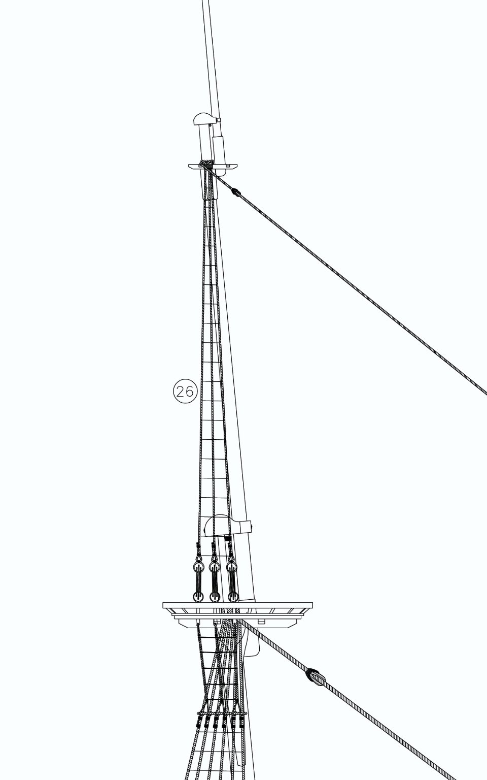
first standing -
*side tackles pendants and main stay tackles pendant
*shrouds
*stays
*backstays
their loops on the mast head have to be placed one above another
second stage fitting running rigging,
on the model I think there is not such strict secquince as in fitting of standing rigging, running rigging could be done in much convenient way...
but logicaly it could be done from bottom to top of the masts fore>main>mizzen
*spritsail
*rigging main sail
*topsail
*topgallant sail,etc.
braces and bowlines could be finaly fitted in last turn ,when all sails will be at place...
-
depends on available resources... best results will be by making all ness-ry sizes yourself using rope making machine...on the market we could find many differnt kinds of such devices from very primitive construction and cheap price to high tech very expansive machines ...funny things that final results will be almost the same doesn't matter which kind of rope making device were used :)))
-
Actually standing rigging is not black...may be dark brown ,as natural hemp tarred looks like?
Running rigging same material but not tarred - should be kind of light ochre-brown color?
But You will need much more different sizes of treads for making good looking rigging, obviously two is not safficient!:)
roughly say , You be need about 10-12 different sizes of the ropes...
and by my opinion ,that treads from the kit ... better don't to use them :((( they have too much "fur" ,on the model they will not looks nice and just will spoil perfectly assembled and painted hull...if possible need try to find treads with smooth surface...
-
-
-
Yes,correct...
topmast need to be remained moveable... it is often lowering down on real vessel of that period, if weather getting worst and serious storm is coming topmast could be lowered down...
Of couse if construction of topmast allowed to do this...at least in 17th century it was common practice as I know....early galleon of 16 century most probably didn't have such option due to there was different type of connection between mast and topmast, kind of permanent connection...

-
I would reccomend first to complete standing rigging, and than to start running rigging ,not vise versa
")
it will be easy for installation...
treads which You use have too much "fur" ,it seems strange on the pictures...don't You consider to make some treatment or even start to use another kind of treads, without fur?
I know Gutermann treads " tera " serie quite good in this respect...
-
Peterson shown us how to rigg shrouds in exploded vew..,however first pair shown fitted at place, around masthead...
please note first burton pendants need to be fitted,than shrouds...
Did You fitt that pendants for side tackles?
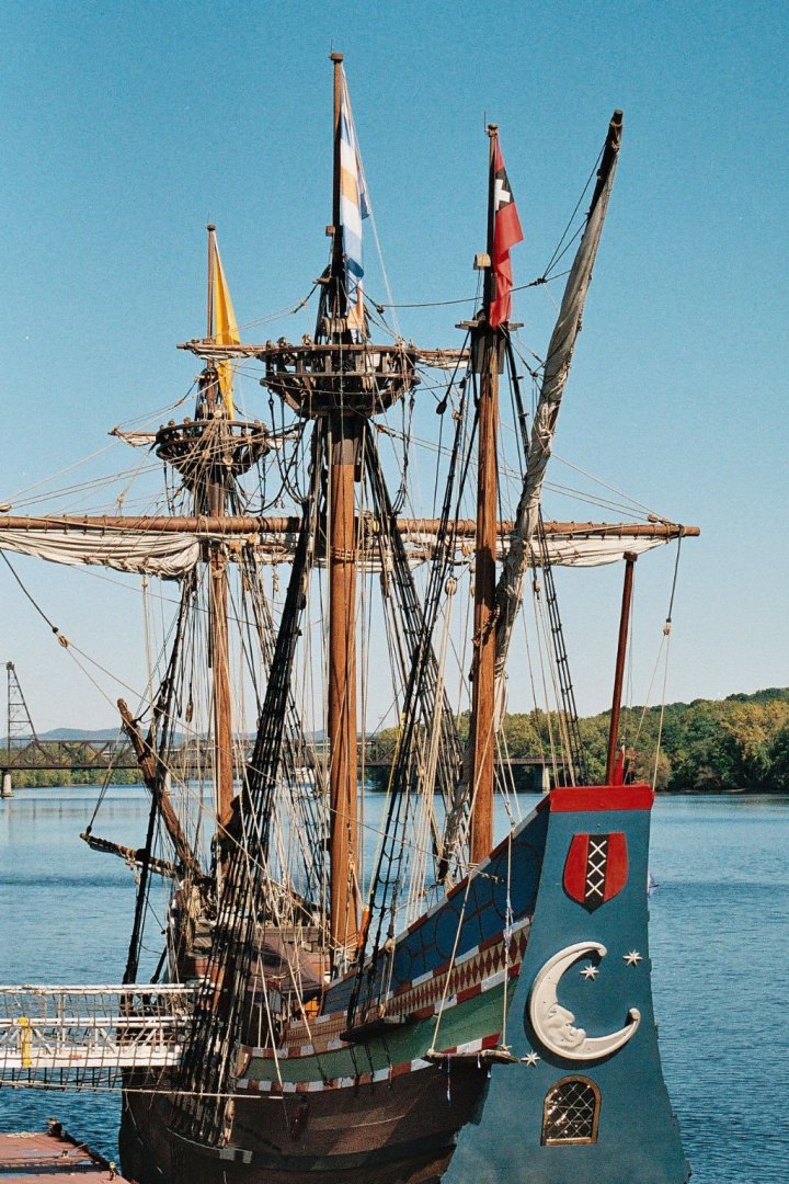
there are some pictures from Ab Hoving book... it is about Dutch shipbuilding ,but in principal rigging the same as used in Mayflower case
-
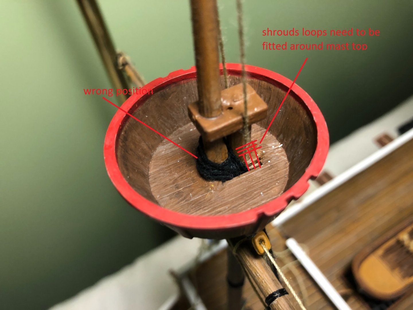
Oh! I understood!:)))
If You would follow assembly instructions it should be OK!:)...
they are very simplified and not supposed shrouds loops creating at all...
but if followed second picture from Peterson book( which tells us how it should be), in that case You did it a little bit wrong...
You made loops around topmast ,which need to be kept " moveable" ,but shrouds loops need to be arranged around main masthead instead of...please check second picture You posted carefully:)))
there are some pictures from Ab Hoving book ,and Winter book
-
Good day BACKER,
Top mast should have possibilities to be lowered down fast ...depehd on weather conditions...
but wnen we will make securing shroud loops like that , it will be very difficult to lowering down topsails
-
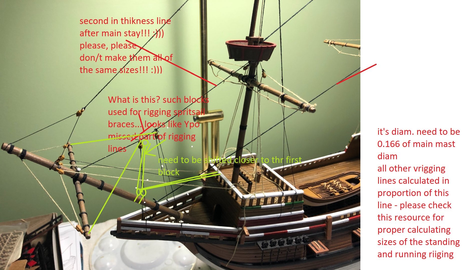
one of the rigging lines You shown by arrows,most probably are main sail tie halliyards and another one most probably topsail lifts... but they doesn't looks like you shown on your model, when all that lines just attached to topsail yard :)))...there is no sence at all to show such rigging arrangements :)))
however , I think ,it is your model, and You can do whatever You like to do on it ,just to get fun !
Wish You All The Best!
Kirill
-
Mayflower rigging is almost identical to the fluit's rigging I shown to You earlier/ Ab Hoving reconstruction ...
Please don't hurry up and check rigging lines of main and top sails and yards rigging and how they are working and attached to belaying points...
Please be familiar with all that lifts lines,clew lines,leach lines of the sails etc. :)))...
a little time need to spend for this study ... and You will find some interesting and funny things You made now in your rigging :)))
-
-
shipman, Thank You for this information!
- shipman and FrankWouts
-
2
.jpg.ad8285374f8c11ada1fed42203b9a5be.jpg)


Spanish Galleon 1607 by kirill4 - FINISHED - Lee - 1:100 - PLASTIC
in - Kit build logs for subjects built from 1501 - 1750
Posted
Thank You very much Tomasz for your attention to my project and remarks")