
MORE HANDBOOKS ARE ON THEIR WAY! We will let you know when they get here.
×


rcmdrvr
-
Posts
420 -
Joined
-
Last visited
Reputation Activity
-

 rcmdrvr got a reaction from Jeff preisler in USS Perry by Jeff Preisler - FINISHED - BlueJacket Shipcrafters - Scale 1/8" = 1'
Very nice model. Your work on deck furniture is excellent. Looking forward to the rigging part.
-

 rcmdrvr got a reaction from mtaylor in USS Perry by Jeff Preisler - FINISHED - BlueJacket Shipcrafters - Scale 1/8" = 1'
Very nice model. Your work on deck furniture is excellent. Looking forward to the rigging part.
-
 rcmdrvr got a reaction from Prowler901 in Nave Egizia by rcmdrvr - FINISHED - Amati - 1:50
The next step was the counter-balance structure. It would appear that the designers used large boulders slug in nets over spaces in the hull to act as counter-balance to the weight of the main mast when it was raised or lowered. I made my boulders by balling up some tin foil and then painting it grey. I then made some very simple nets with the ropes and hung from the poles over the space in the hull previously constructed. I am not sure how these counter-balances worked since most of the rigging of these structures appear to be below decks and not visible.
-
rcmdrvr got a reaction from Prowler901 in Nave Egizia by rcmdrvr - FINISHED - Amati - 1:50
It appears that the builders of these Egyptian ships would stretch a rope from the front to the rear of the ship and then put the rope under tension by twisting. I assume this would offset the opposite forces placed on the keelless hull as the ship was loaded. The following photos show my construction of this tension line; including the fore and aft mounting and the "tensioner".
-
 rcmdrvr got a reaction from Knocklouder in Nave Egizia by rcmdrvr - FINISHED - Amati - 1:50
The next step was the counter-balance structure. It would appear that the designers used large boulders slug in nets over spaces in the hull to act as counter-balance to the weight of the main mast when it was raised or lowered. I made my boulders by balling up some tin foil and then painting it grey. I then made some very simple nets with the ropes and hung from the poles over the space in the hull previously constructed. I am not sure how these counter-balances worked since most of the rigging of these structures appear to be below decks and not visible.
-
rcmdrvr got a reaction from Knocklouder in Nave Egizia by rcmdrvr - FINISHED - Amati - 1:50
It appears that the builders of these Egyptian ships would stretch a rope from the front to the rear of the ship and then put the rope under tension by twisting. I assume this would offset the opposite forces placed on the keelless hull as the ship was loaded. The following photos show my construction of this tension line; including the fore and aft mounting and the "tensioner".
-
 rcmdrvr reacted to Scotty W in Swift 1805 by Scotty W - FINISHED - Artesania Latina - 1/50th scale - Virginia Pilot Boat
Thanks rcmdrvr! I find the bourbon helps control my shaking working at this scale and the neurapathy and numbness in my fingers doesn’t help either. The other side of the sword is there may be some boo-boos in planning or execution due to too much of the brown liquid at time. lol
-
 rcmdrvr got a reaction from Peanut6 in Swift 1805 by Scotty W - FINISHED - Artesania Latina - 1/50th scale - Virginia Pilot Boat
After a lot of work and some frustration; it looks like you obtain an nice first planking. Like a nice smooth bourbon myself.
-
 rcmdrvr got a reaction from Scotty W in Swift 1805 by Scotty W - FINISHED - Artesania Latina - 1/50th scale - Virginia Pilot Boat
After a lot of work and some frustration; it looks like you obtain an nice first planking. Like a nice smooth bourbon myself.
-
rcmdrvr reacted to Doc Watson in HMS Fly by Doc Watson - Amati/Victory Models - 1:64
'On the shoulders of giants...'
I have to say that the build logs here for HMS Fly/Pegasus have been an inspiration to me on how to navigate my first true 'scale' ship. Particular thanks go to Blue Ensign for posting his Pegasus build... TWICE... after the great crash.
I received the kit a few weeks ago but was torn between my 'one at a time' philosophy of boats under construction. That has now changed and I'm going to make a slow start (and probably build) of this excellent kit.
In December 2022 I started building HMS Golden star and am using it to resurrect some woodworking skills not used since building Kiel-Kraft balsa spitfires, Fokker triplanes and Stukas back when my age was a single digit (I'm now over halfway to 3 digits!). The Golden Star is progressing but am a little 'hung up' on the fact that its not a true scale model of any particular ship, but as a starter in this hobby it serves its purpose as an excellent training build. There is yet another build on the go of a scratch built HMS Victory but I needed to get retrained hence the current builds.
The current plan (and this may and probably will change) is to build it with full cabins at the rear (again thanks Blue Ensign), leave the hull planked (in Boxwood) unpainted and not coppered. Guns and carriages will be changed to Syren, boat kits will be added and the thought of dinner by candlelight in the Captains cabin is very tempting (flickering LED lights).
So after breaking etiquette by not showing the 'opening the box' series of photos in my Star build here they are...
The box
And inside....
Lots of plans which I haven't looked at yet...
Brass photoetch....nice.... (cant be as hard to assemble as a 1/24 scale Martin Baker ejection seat in PE can it?)
Hours of fun here....
I've got wood....
and finally the 4 MDF sheets.
I think I will spend the evening dry fitting the hull and building the cradle, although a 'scale' slipway will be created for display purposes (which I probably wont need for a few years!).
Avast me hearties!!!!!!!!
-
rcmdrvr got a reaction from Jeff preisler in US Brig Niagara by Abelson - Model Shipways - 3/16" scale
Just browsed yourbuild log. Probably one of the best for extensive photography. Will certainly help the builders that follow you with a Niagara build of their own.
-
rcmdrvr reacted to Kevin in Lady Eleanor by Kevin - FINISHED - Vanguard Models - 1/64 - Fifie fishing boat - built Dec 22, 2022 to Jan 23, 2023
Good Morning everyone
Thank you for comments and likes
This is something i dont say very often
I finished something
The Lady Eleanor is finished
just over 4 weeks,
OOB
Halfords rattle cans
Everbuild C/A
Titebond - quick and thick wood glue
Thank you @chris watton
-
rcmdrvr reacted to Elder_dumpster in Krabbenkutter CUX 87 by Elder_dumpster - Billings Boats - 1:30
Current state.
A bit more priming, filling and sanding on the hull to do.
-
rcmdrvr reacted to Elder_dumpster in Krabbenkutter CUX 87 by Elder_dumpster - Billings Boats - 1:30
My second Billings boat, in fact second ever wooden model.
Started May 202, I don't have huge amounts of free time to work on her, so it's sporadic progress.
So far the hull is planked and almost ready for painting, but in parallel I've been working on the wheelhouse.
My impressions of the kit aren't all positive and it is clear this one came from the Chinese factory. The wood quality was a lot better when I tackled Smit Rotterdam about 20 yrs ago. The deck planks were missing - but I filled in an RMA form on Billings' web site and received 25 0.8*5mm mahogany planks a few days later. Excellent service!! I did gain 25 2*2mm strips that obviously had been mistakenly put in as the deck planks. I'm trying to incorporate the bonus wood where I can, to add detail. The plans are adequate, but the build instructions are 'the helicopter view' and not a lot of use for the beginner like me.
More photos to follow
-
rcmdrvr reacted to Elder_dumpster in Krabbenkutter CUX 87 by Elder_dumpster - Billings Boats - 1:30
Eventually gave up on the weather and made a spray booth thing. It works pretty well and was cheap to make 3 euros for the hardboard, 19 for the bathroom extractor, plus some 100mm ducting I had already.
Considering I haven't used an airbrush for many years and the one I have is a cheap version, I'm quite pleased with the results. Although the blue is a bit dull in patches, so will probably give it another coat at some point.
The rubbing strake and top rail will be black too.
-
 rcmdrvr got a reaction from amateur in Nave Egizia by rcmdrvr - FINISHED - Amati - 1:50
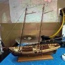
Last night I was able to construct the main mast. The mast is very different than we find on most sailing ships. It is a very elongated triangle with cross pieces to support the rigging. I fashioned the mast over the plans. The cross pieces require some care drilling of holes (I used a dremel drill stand that worked quite well). It seems the main masts on these ships were retractable to a "saddle" which will be constructed near the stern. Because the mast is retractable, the rope wrapping in the interior of the hull was a bit complicated.
-
rcmdrvr got a reaction from amateur in Nave Egizia by rcmdrvr - FINISHED - Amati - 1:50
Amateur: Had play around with the math since I think in inches and feet. The model is about 1 foot in length. At a scale of 1:50 I estimate the full scale ship would have been about 50 feet in length; which I believe is close to 15 meters.
-
 rcmdrvr got a reaction from ccoyle in Nave Egizia by rcmdrvr - FINISHED - Amati - 1:50
Last night I was able to construct the main mast. The mast is very different than we find on most sailing ships. It is a very elongated triangle with cross pieces to support the rigging. I fashioned the mast over the plans. The cross pieces require some care drilling of holes (I used a dremel drill stand that worked quite well). It seems the main masts on these ships were retractable to a "saddle" which will be constructed near the stern. Because the mast is retractable, the rope wrapping in the interior of the hull was a bit complicated.
-
 rcmdrvr got a reaction from VTHokiEE in Nave Egizia by rcmdrvr - FINISHED - Amati - 1:50
Thanks for the rope advice. This model is one of the first times I have had to do extensive rope rigging, wrapping, etc. I have learned that I have a lot to learn about this art. For example, I am not sure about how to tie off ends, etc. Next time I will look into purchasing rope. This little model would have cost a fortune. There must be eight spools of rope included in the kit. I have been using yards of the stuff.
-
rcmdrvr got a reaction from VTHokiEE in Nave Egizia by rcmdrvr - FINISHED - Amati - 1:50
Last night I was able to construct the main mast. The mast is very different than we find on most sailing ships. It is a very elongated triangle with cross pieces to support the rigging. I fashioned the mast over the plans. The cross pieces require some care drilling of holes (I used a dremel drill stand that worked quite well). It seems the main masts on these ships were retractable to a "saddle" which will be constructed near the stern. Because the mast is retractable, the rope wrapping in the interior of the hull was a bit complicated.
-
rcmdrvr got a reaction from VTHokiEE in Nave Egizia by rcmdrvr - FINISHED - Amati - 1:50
Well, on to the "Command Deck". This is my name for the decking that was fashioned on top of the hull and then surrounded on three sides by railing. On the model you must first make a foundation. This consists of doweling which is then lashed to the sides of the hull. The actual deck is fashioned from a triangular piece of thin ply that is "planked" and then "framed". I also stained this decking with light oak but was not very happy with the results. It is darker and more red that I would have liked. Oh well.
The railings were a bit tedious but I like the result. The lower piece of the railings had to be notched for the lashing. I used a dremel rotary tool clamped to my bench to accomplish this. To assist in lashing, I dipped the end of each "rope" in thin CA and let it dry to form a one inch length that was stiff like a needle and could be used to guide the rope.
-
rcmdrvr got a reaction from VTHokiEE in Nave Egizia by rcmdrvr - FINISHED - Amati - 1:50
The next step proved to be a bit difficult. Egyptian ships did not have keels. They stablized the hull by stretching a large rope in a arch between the bow and stern. At the bow and stern they crafted "hard points" to attach this rope truss. The hard points had to be quite strong so they used heavily wrapped rope as a strap to hold the hard point to the hull. They would wrap the strap around the hard point structure and then loop under the hull. My final photo will give you an idea of what I am trying to describe. The plans called for making the strap by cutting out a copper strip from thin copper sheet and then wrapping this with rope. I cut out the pattern from the plans and quickly discovered it was not long enought to wrap around the hull. I lengthened the pattern but traced the new pattern on the copper sheet. However, I just managed to destroy the sheet trying to cut out the copper strap. I really have to improve my metal fashioning skills.
I instead tried to duplicate the straps I saw in photos, when I researched Egyptian ships on the internet, using rope. I took two lengths of 1.3 mm rope and wrapped them with .7 mm rope to form a thicker straight rope for the strap. I then wrapped these straight ropes around the dowl that would become the hard point and then around the hull. Finally I attached the two straps together in the center to form the final single strap. I hope my photos do a better job of showing what I fashioned than my descriptions. During the wrapping process I would coat the wrapped portion of the straps with thinned wood glue and then dry it in a fruit dehydrator. This worked great. The wrappings stayed put but the strap remained flexible so I could work with it. Anyhow, I think I was able to achieve an acceptable result. The last two photos show first the bow and then the stern hard points for the truss rope; which will be installed later.
-
rcmdrvr got a reaction from VTHokiEE in Nave Egizia by rcmdrvr - FINISHED - Amati - 1:50
Decking is next. The kit provided a laser cut plywood deck that you plank with wooden strips. Unfortunately the plywood deck was a bit small. I held the plywood deck in place with a clamp so that I could cut the planking to cover the gap between the plywood deck and the sides of the ship. This worked well. After planking there is some hole drilling and adding rope loops before the deck is glued into place. With the decking in place; I think the model is beginning to take shape.
-
rcmdrvr got a reaction from VTHokiEE in Nave Egizia by rcmdrvr - FINISHED - Amati - 1:50
Well, the next step is the simulated rope weaving on the hull. The process began with placing a strip of tape along the hull so that I could mark where the holes would be drilled. There are two rows of holes, each row being offset by 1/2 the distance between the holes. Then came the drilling process. I used a hobby knife with a sharp blade to make a small starter hole at each marked location. I then used a dremel rotary tool to drill the hole. There were a bunch. I next wove the bow and stern with two strands passing through the holes. The instruction booklet did a good job illustrating how this should be done. Next I wove the top and bottom rows along the length of the hull. Again, it was two strands passed throught each of the holes. This was also well illustrated in the booklet. Finally a single, small diameter strand is woven between hull length threads. I used two pins to raise the upper and lower ropes in order to be able to pass the lighter thread. One tip in the process. I dipped the end of each thread in thin CA and waited a few seconds for the ends to become very stiff. This made it much easier to weave thru the holes.
-
 rcmdrvr got a reaction from Prowler901 in Nave Egizia by rcmdrvr - FINISHED - Amati - 1:50
Last night I was able to construct the main mast. The mast is very different than we find on most sailing ships. It is a very elongated triangle with cross pieces to support the rigging. I fashioned the mast over the plans. The cross pieces require some care drilling of holes (I used a dremel drill stand that worked quite well). It seems the main masts on these ships were retractable to a "saddle" which will be constructed near the stern. Because the mast is retractable, the rope wrapping in the interior of the hull was a bit complicated.