Louie da fly
-
Posts
7,973 -
Joined
-
Last visited
Content Type
Profiles
Forums
Gallery
Events
Everything posted by Louie da fly
-
 Looking good,mate. It's certainly hard to know how the caique could have been sailed with those oars aboard. It doesn't look like there'd be room for the crew - even if there were only six of them (a pair of oars each) plus the coxswain. And I can't see it being practical to slide them beneath the thwarts, either. Unless there was some form of 'holder' for them running down the centre of the boat, like unto the histodokai (crutches for the lowered masts) on a dromon - see post # 802 at https://modelshipworld.com/topic/10344-10th-11th-century-byzantine-dromon-by-louie-da-fly-finished-150/page/27/ but perhaps supported along the centre of the thwarts rather than overhead. Steven
 -
Carraca Atlantica by Dripaj
Louie da fly replied to Dripaj's topic in - Kit build logs for subjects built from 1501 - 1750
Quite right. There's absolutely no historical justification for these structures in the 15th or early 16th centuries - nothing like these came into use until the late 16th/early 17th. I pointed this out to Kikatinalong (g'day, mate!) when he was doing his own build and he agreed with me and got rid of them. Good thing, too. Dripaj, I'm not sure if you've seen my collection of carrack pics on Pinterest, but you might find them useful in your build - see https://au.pinterest.com/lowe1847/carracks/ . From contemporary pictures, I'd say the configuration you're adopting for your carrack would be be appropriate for a vessel from some time after 1510-1520. You might find those gun carriages are pretty close to right for that period - have a look at the ones I made for my Great Harry, based on carriages recovered in the 19th century from the Mary Rose (sank 1545) - post #97 at . Tartane has also done a very nice full-sized reproduction at And yes, the metal castings are pretty crappy. The figurehead looks like a mutant duck . . . Steven -
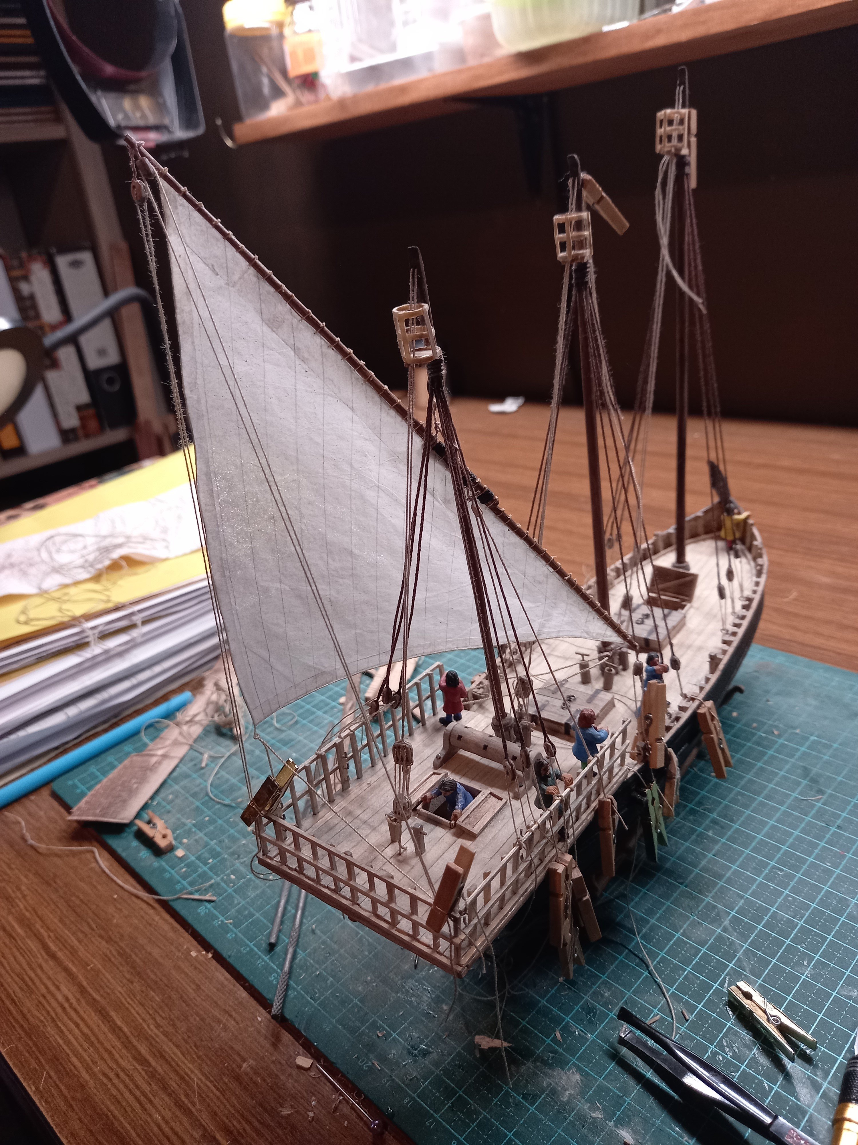
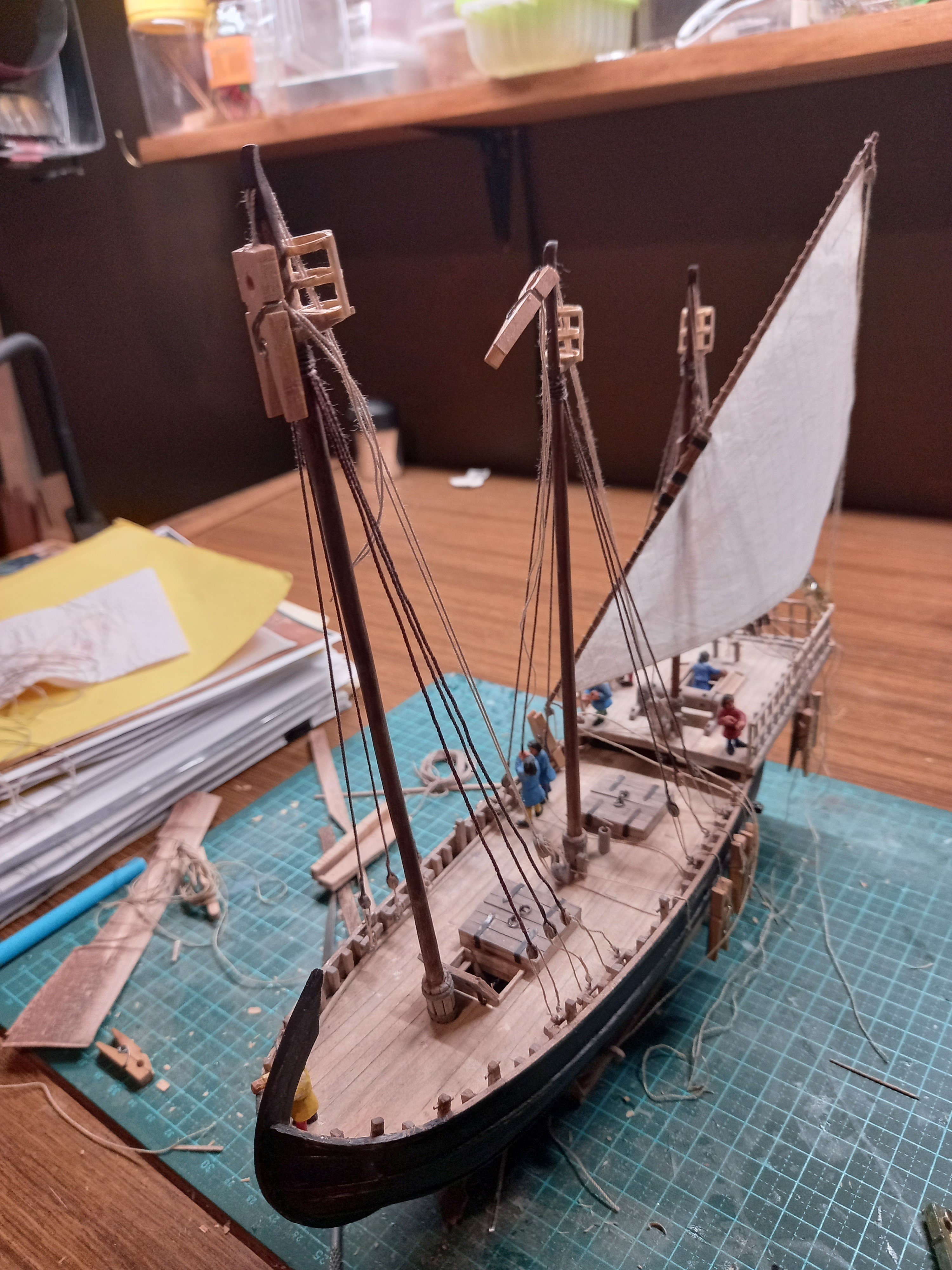
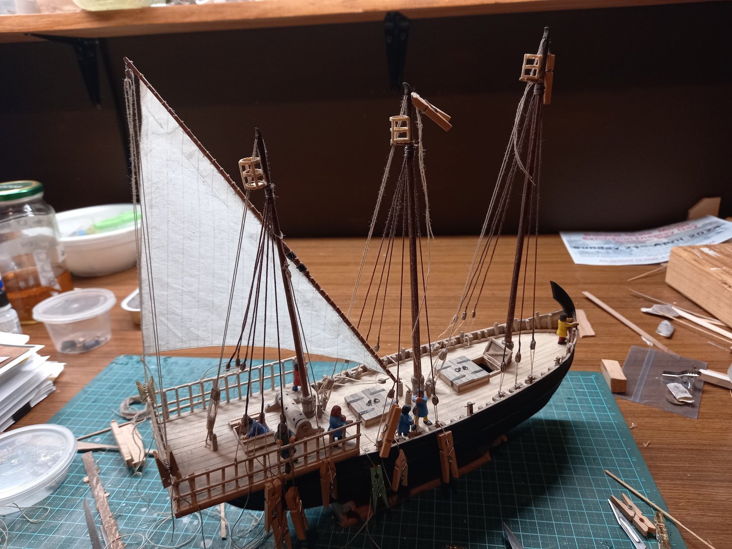
Thanks everybody for the likes. That's very interesting, Mark. What, our ancestors weren't all brutish ignorant barbarians? And a little progress - the mizzen lateen in place and tentatively belayed. Note that following Landström's book The Ship I've got the leeward shrouds loosened to allow the sail free play. I'm thinking about how to give them nice catenary curves. Steven


- 508 replies
-
- 17
-

-

-
Looks like a very good project. I'll pull up a chair and watch progress, if I may. Steven
-
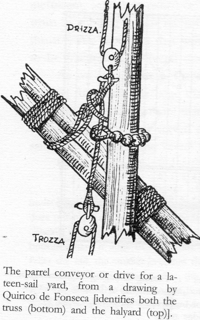
By the way - note that in the drawing the parrel (the rope that holds the yard to the mast) has trucks (those balls that rotate to allow the yard to run more easily up and down the mast), but I didn't add them, as this ship is from about 1150 AD and parrel trucks don't appear in contemporary pictures till the early 1400's. Steven
-
Moving right along, mate! After your last model I'm definitely following this one. Steven
- 55 replies
-
- 3
-

-
-
- miniature
- Brandenburg State Yacht
- (and 1 more)
-
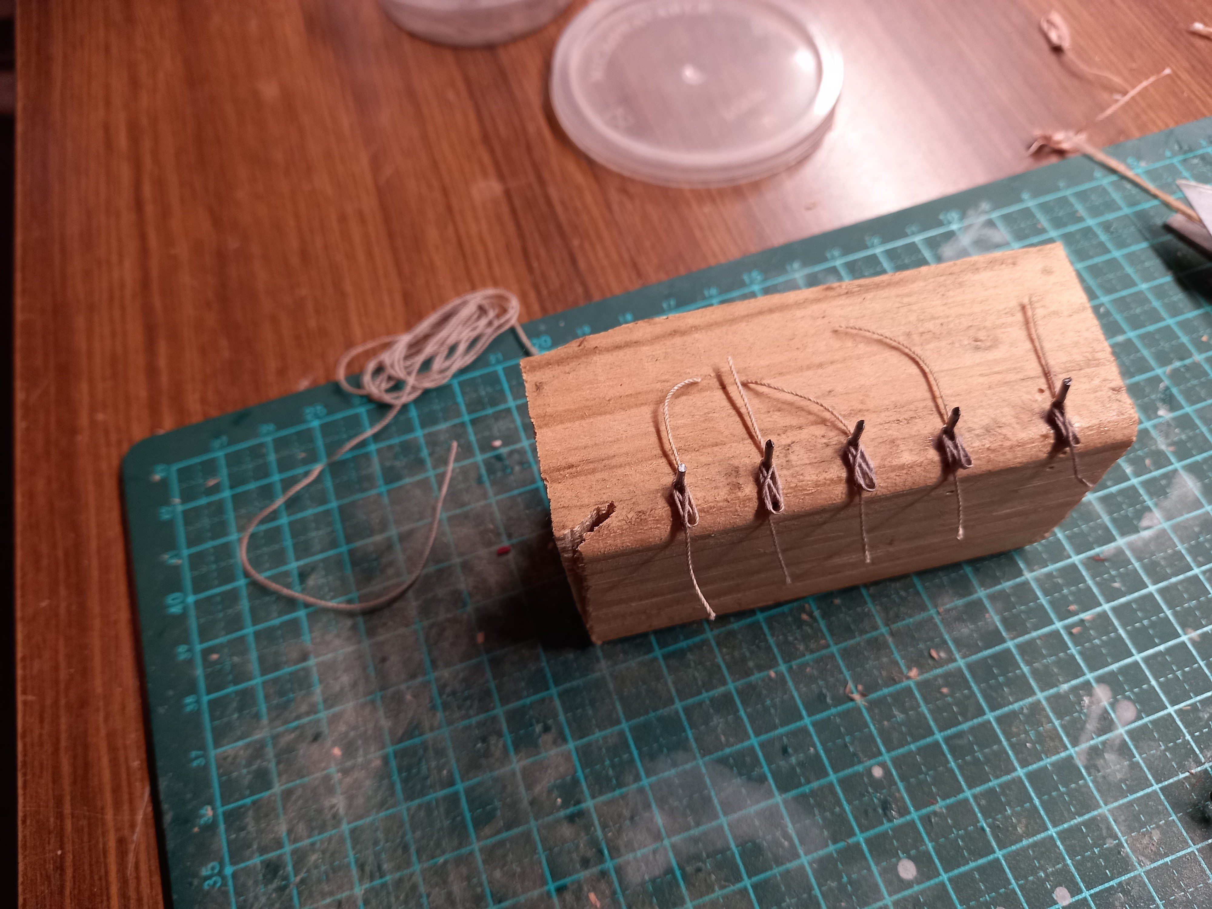
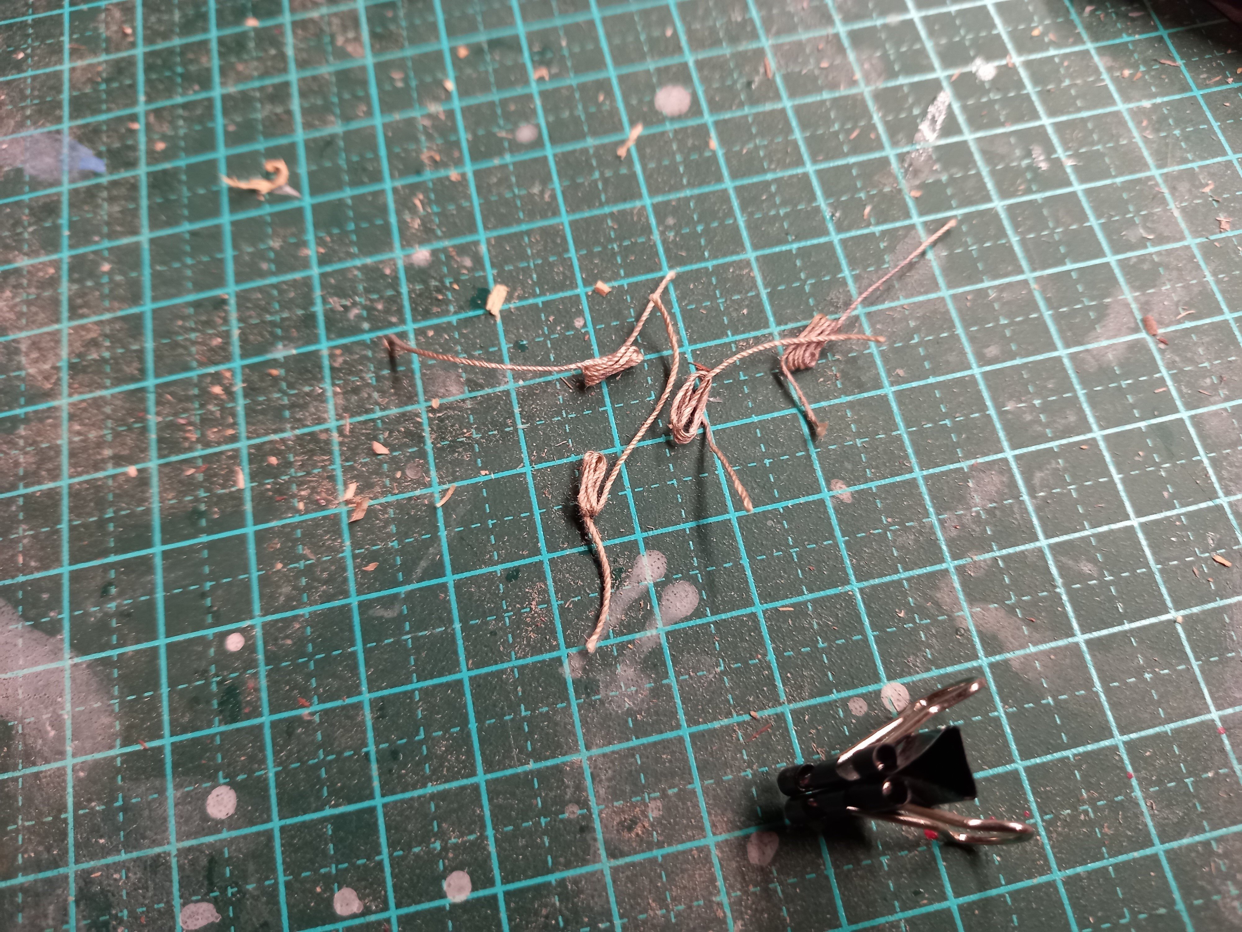
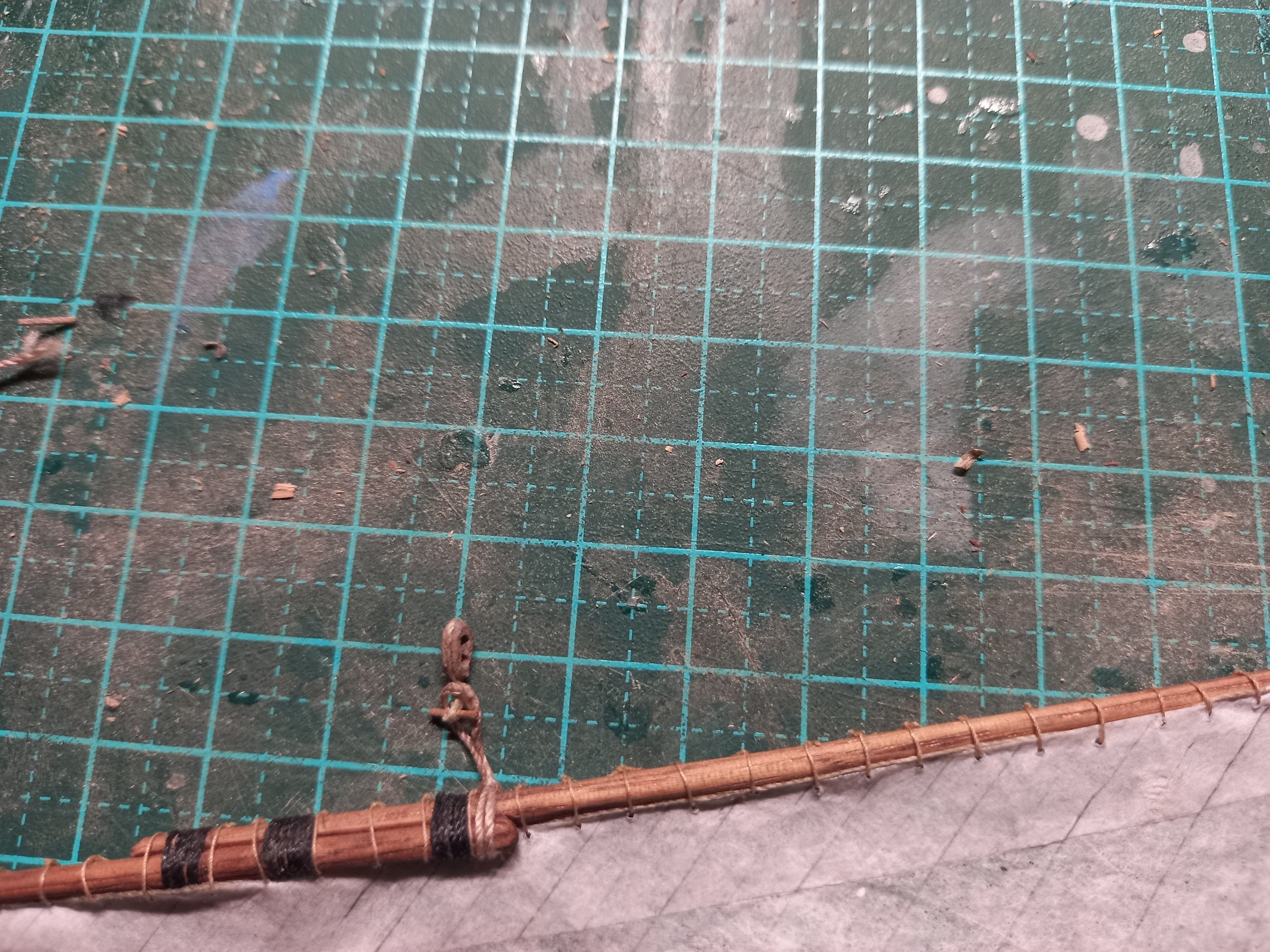
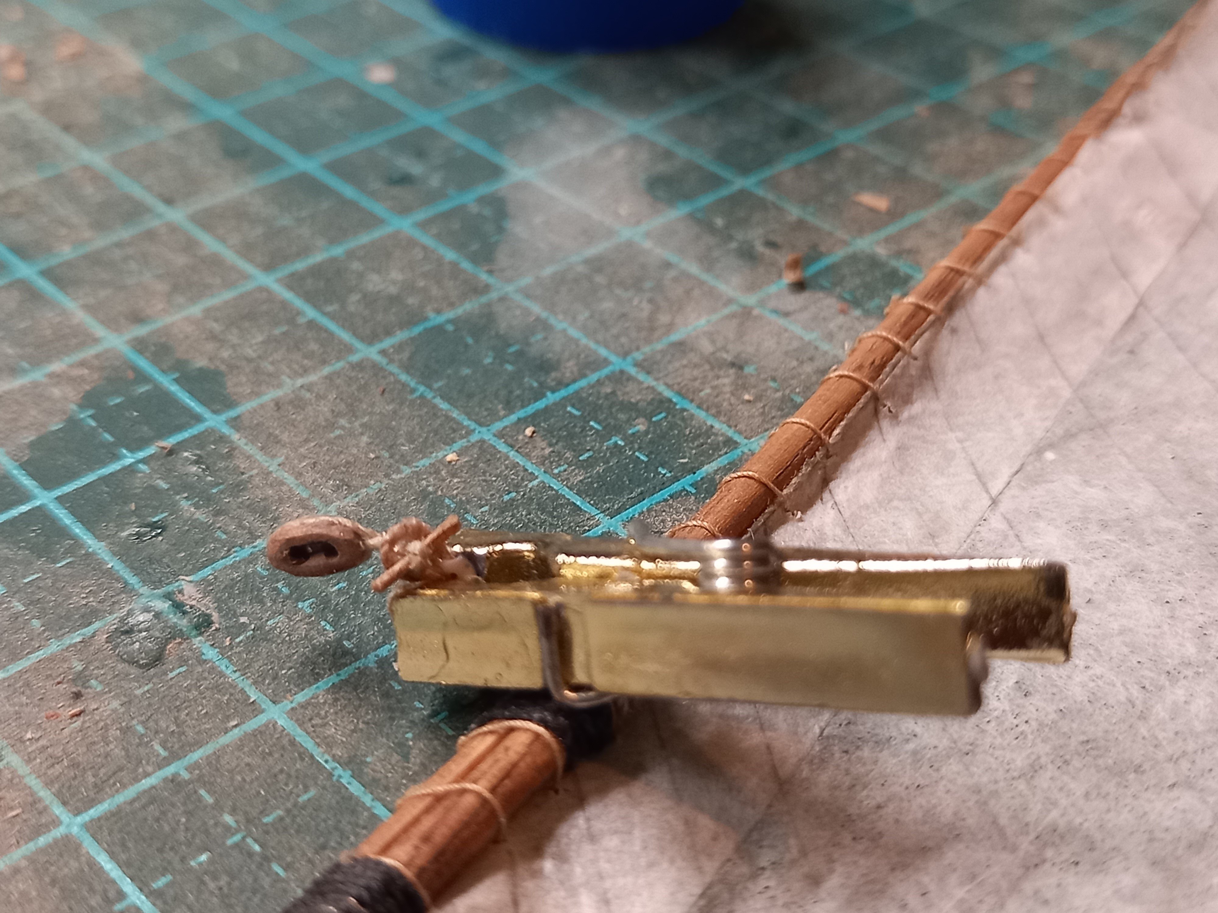
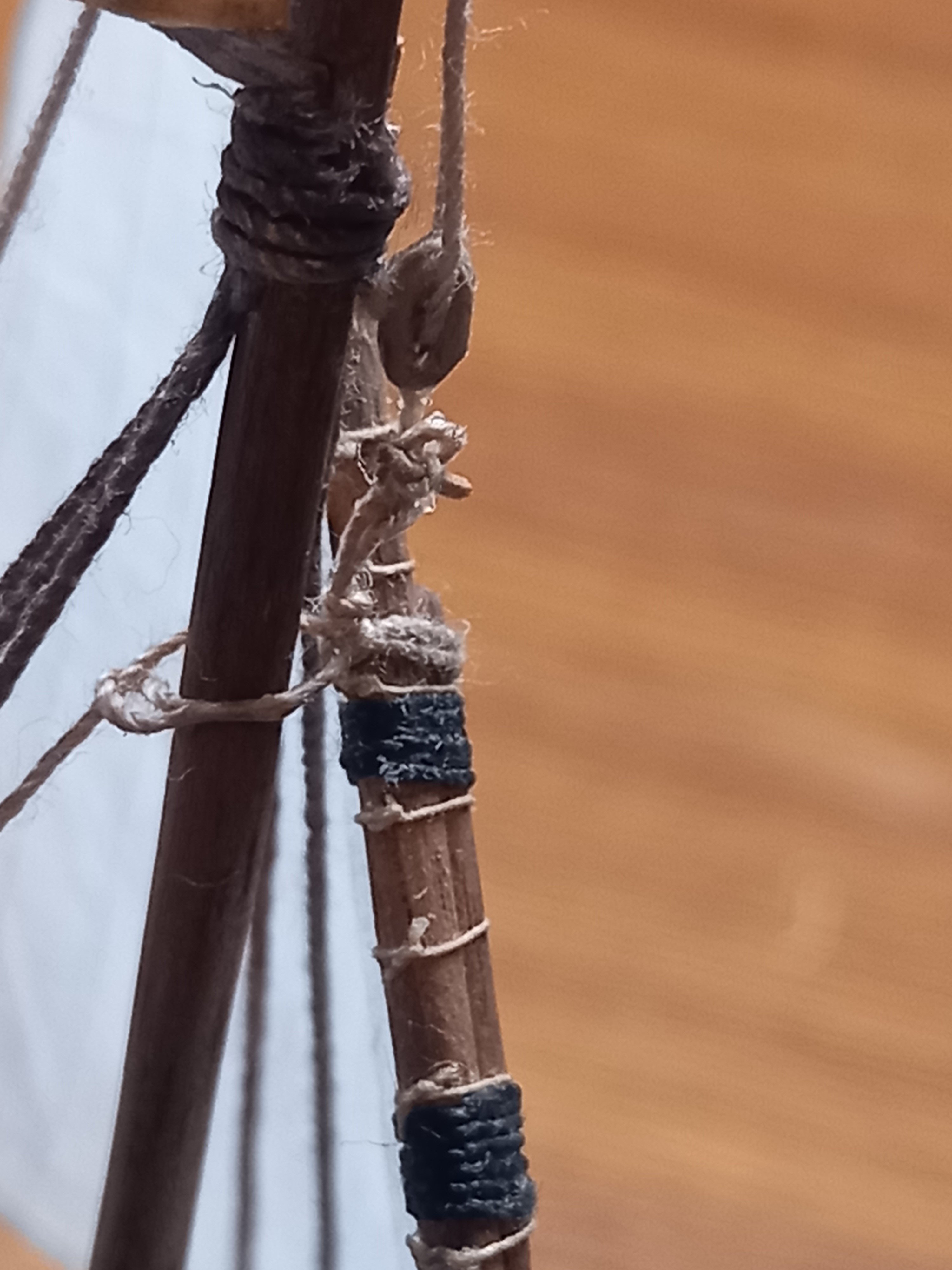
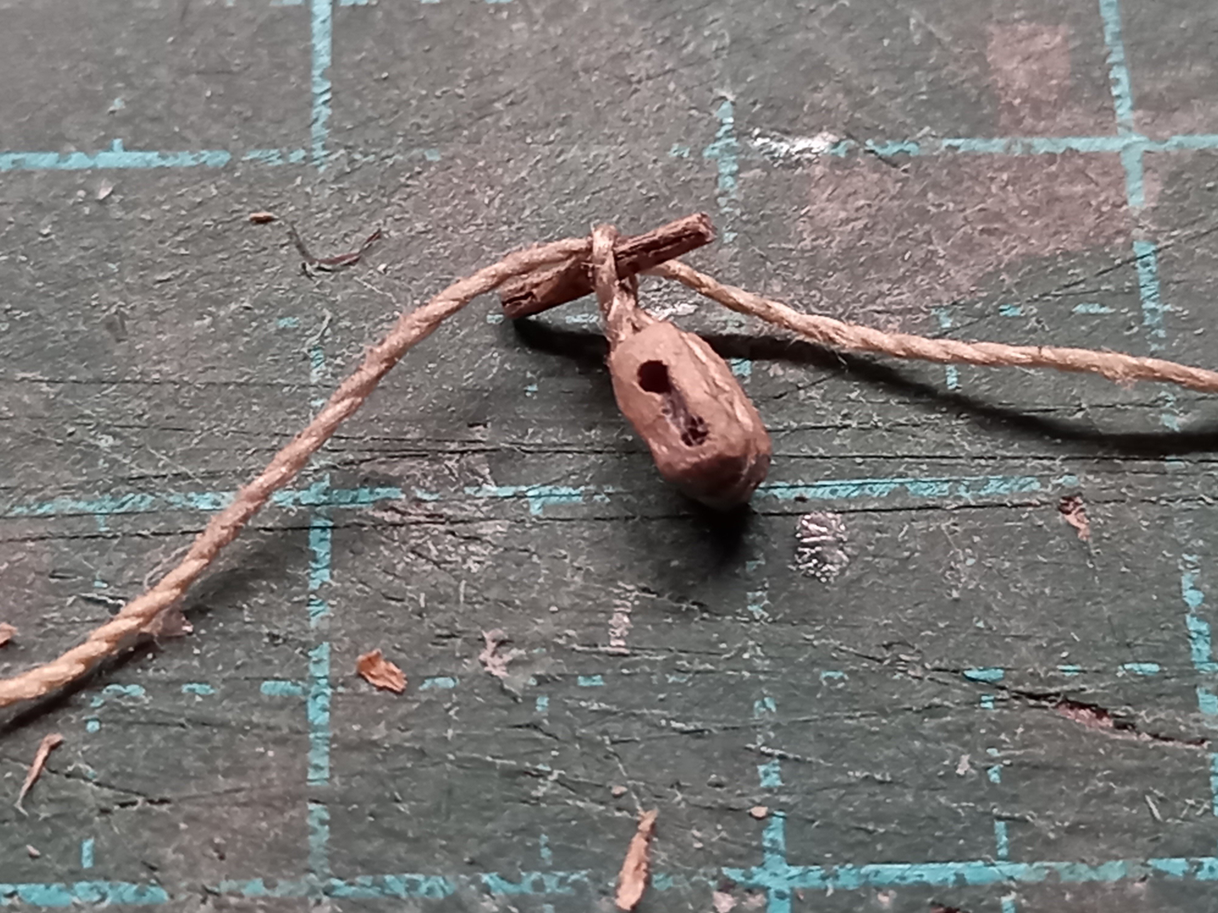
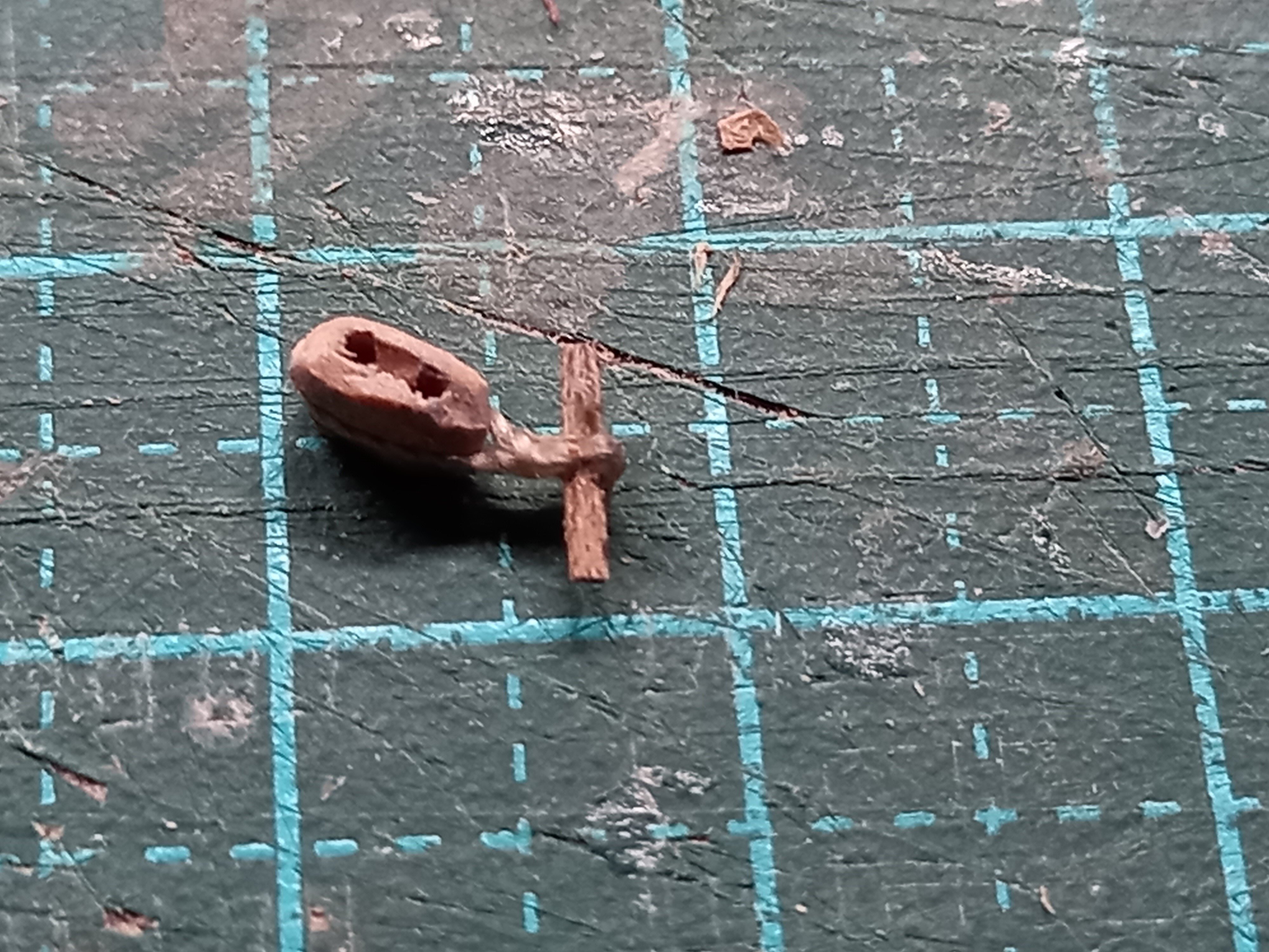
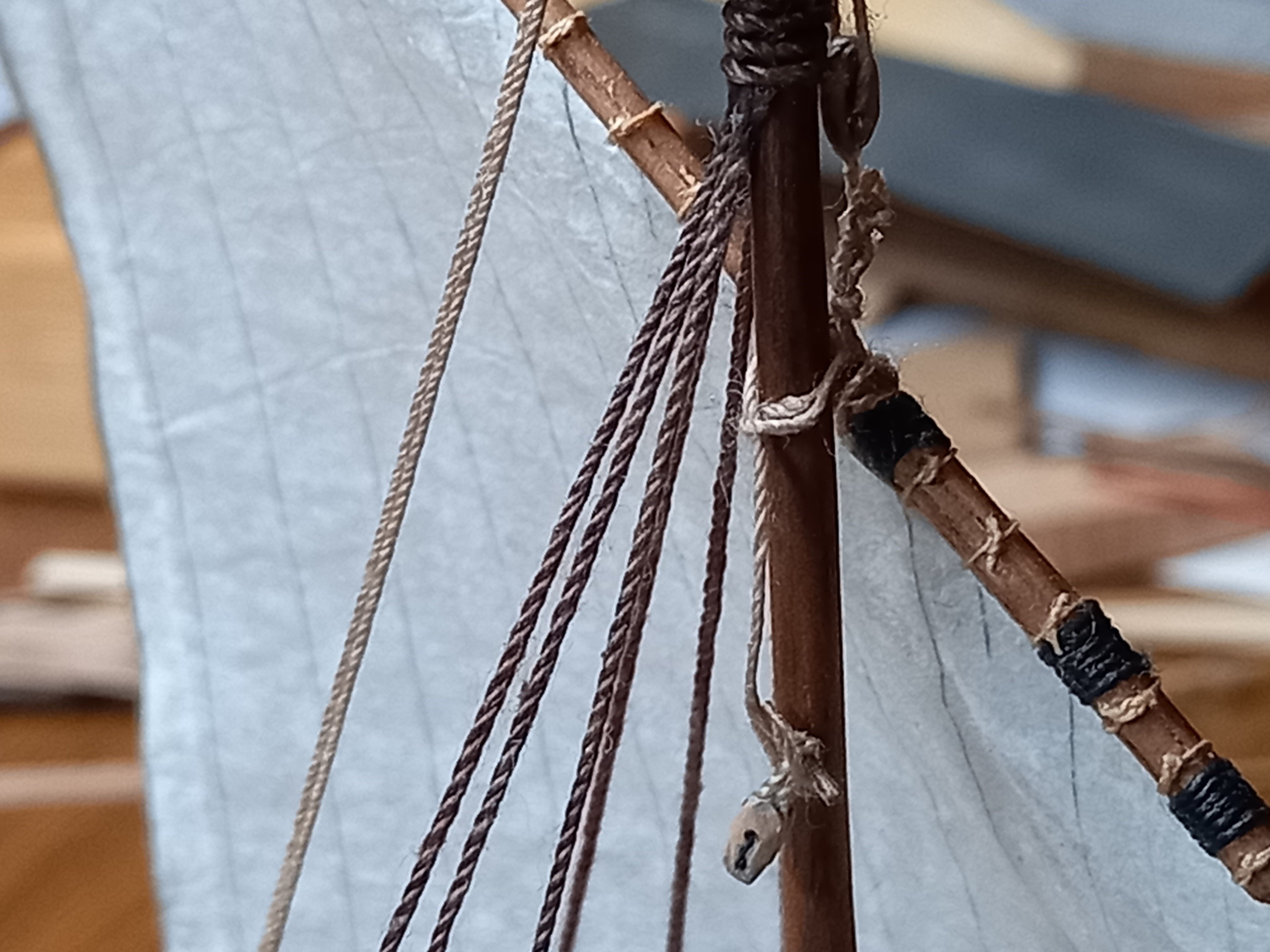
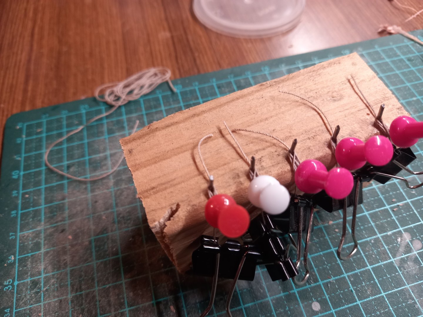
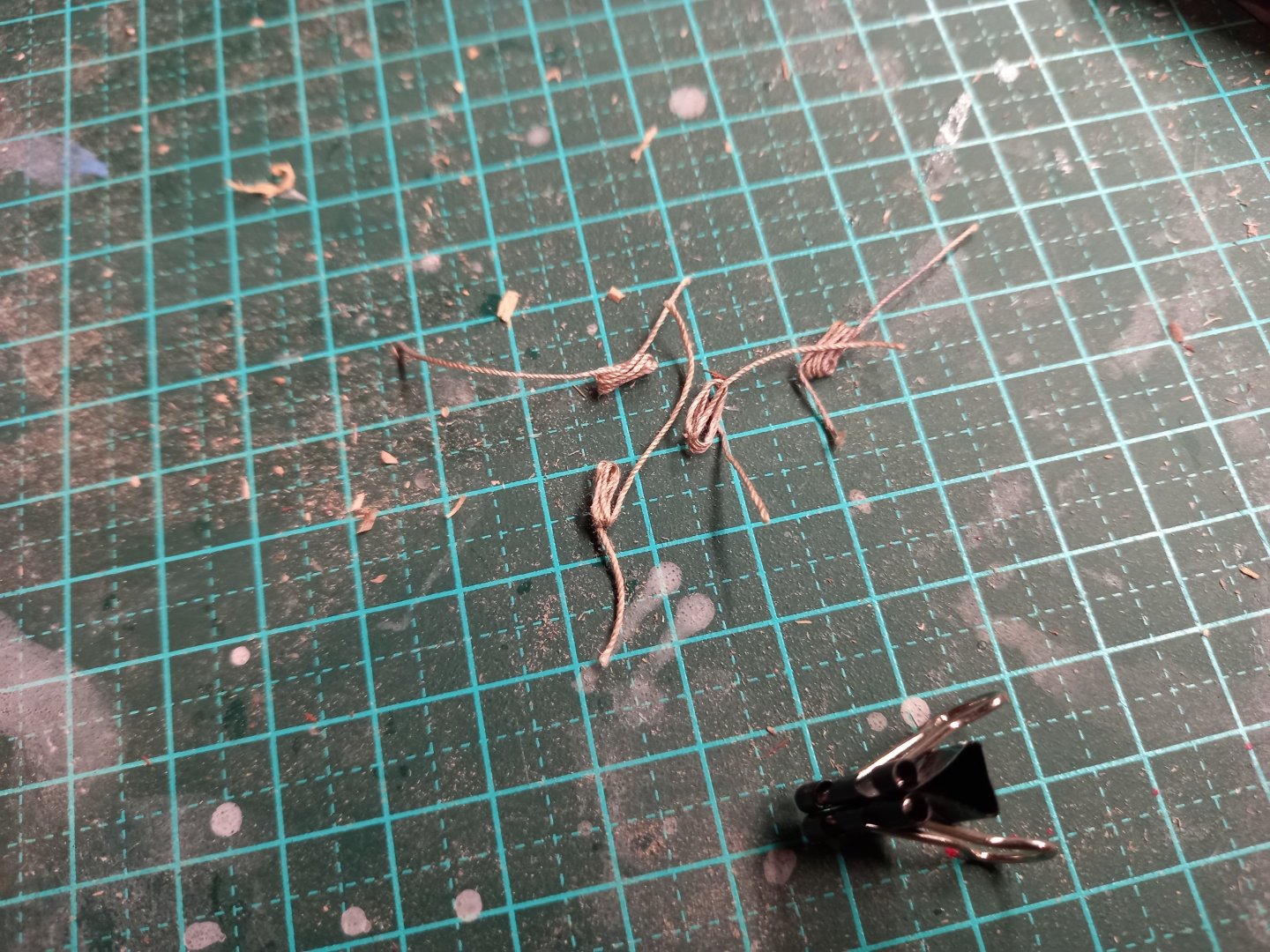
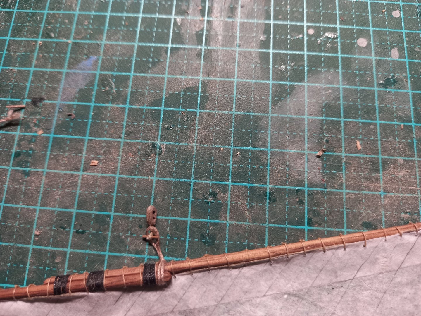
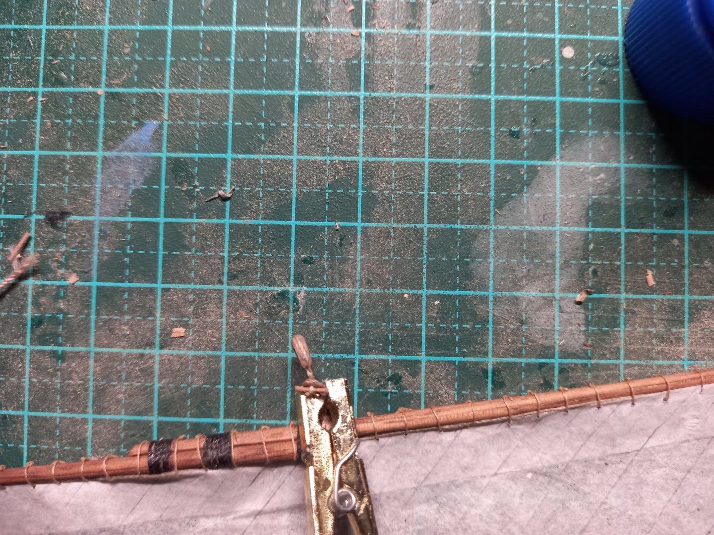
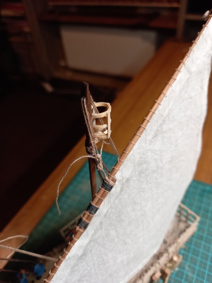
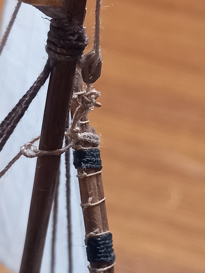
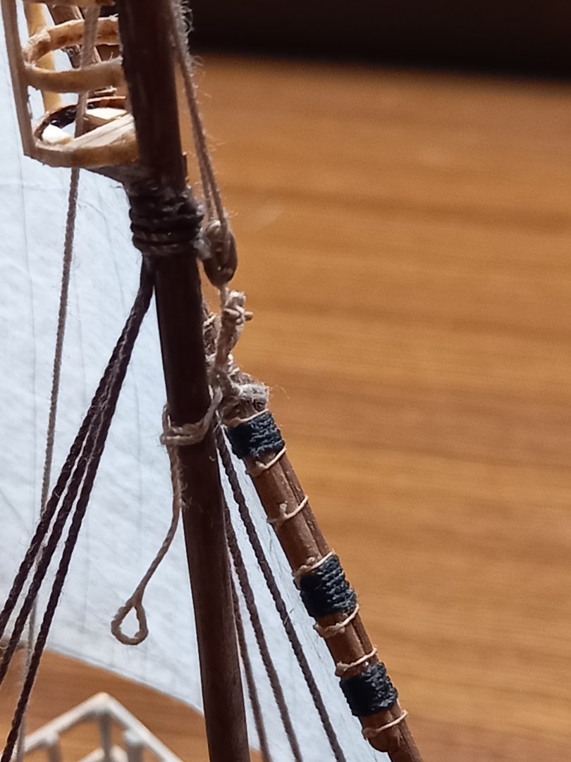
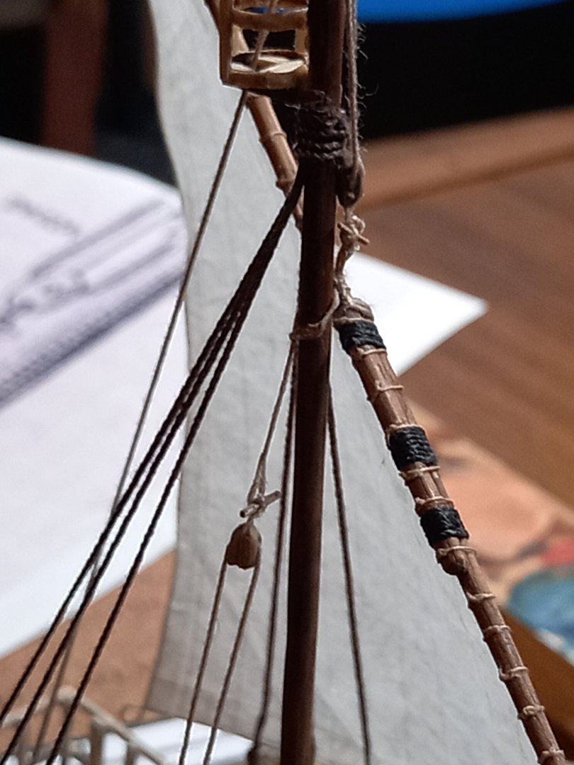
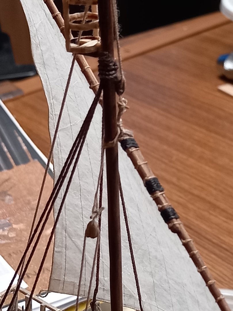
Working on making rope coils for the shroud blocks - a technique I pinched from Ulises Victoria of MSW (thanks, mate!). They're pretty small and fiddly, but I think they'll do the job. And now something I've been avoiding for months - just too chicken to start because I dreaded stuffing it up - the halyard/trozza (truss) assembly that holds the lateen yard at the correct height and ties it to the mast so it doesn't flop around. Yes, I'd previously done it on the dromon build, but (a) I'm not sure I got it right back then and (b) it's so fiddly. The thing is, on lateeners (now and back then) they seem to divide the rig up into modules connected by toggles, rather than make a whole assembly in one piece. This is very much more convenient when sailing in the real world, but rather more complicated when making a model. So here it goes, step by step: First, the tye around the yard itself ; A little loose in the loop, so I glued it together a bit tighter I'd started out with a doubled halyard, as the sheaves in the calcet at the top of the mast were always shown double, but apparently it's a single halyard that goes through the block and back down. So I got clever and faked a continuous loop of halyard through the block at the top of the assembly, by running the two ropes through the block from opposite sides,gluing and then cutting them short, so they looked like a single rope looped through the block. And then the really fiddly bit - making the truss and running it around the mast, wrapped around the tye and back down to its downhaul. Took me about a dozen attempts before I got it right.Sorry about the hairy rope, but it's not visible to the naked eye. And then the block attaching the truss to its downhaul via a toggle: And attached to the loop from the truss (VERY fiddly getting the toggle through the loop!) And all in place (I still have to figure out how to belay the lower end). Just have to do it two more times for the other two masts, and I'm right . . . Steven


- 508 replies
-
- 16
-
-
Welcome to MSW! You're sure to have a lot of fun. I like the name of the music group "cabestan" - en Anglais capstan! Steven
-
Beautiful job, mate. She looks much more like a real wooden ship than most plastic models manage to. Steven
- 69 replies
-
- 1
-
-
- spanish galleon
- Imai
- (and 1 more)
-
A nice solution to the problem, Peter. I had a problem with the shrouds on my Great Harry build - though not the same as yours - mine had to do with when I added the deadeyes, as the shrouds had already been made and ratlines added - and I had to find a solution that I wouldn't recommend under normal circumstances, but in that specific case it worked. Horses for courses. Steven
- 69 replies
-
- 2
-
-
-
- spanish galleon
- Imai
- (and 1 more)
-
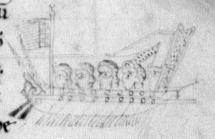
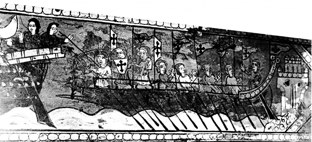
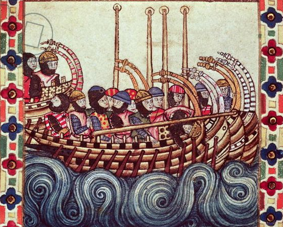
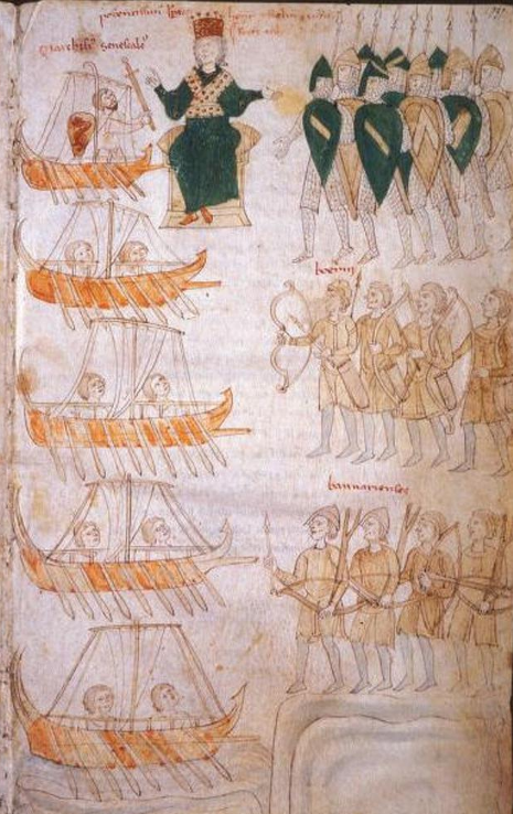
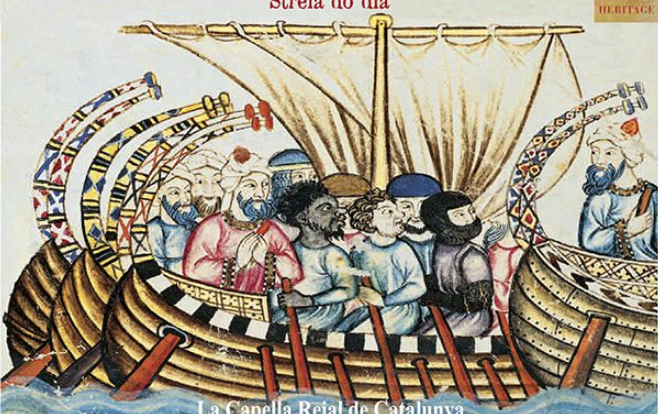
Great idea. There are some great contemporary illustrations to base one on. 1173-1196 Galley - Annals of Genoa f. 70r. Double-banked galley. 12th century: Museu Nacional d'Art de Cataluna from Cantigas de Santa Maria - late 12th century Spanish. Note - in accordance with the text, the first galley's mast is broken. from Peter of Eboli's Liber ad Honorem Augusti, Italian 1194-96 Steven
- 176 replies
-
- 3
-
-
-
- la reale de france
- heller
- (and 2 more)
-
Quite possibly. I was somewhat surprised to find that not all the oarbenches on a galley necessarily got used all the time. Sometimes only half the oarsmen were rowing while the other half had a rest - and I'm sure other configurations existed as well. After all, cooking only happened at certain times of day, and perhaps that pair of oars (one each side, for balance) were "retired" while that was happening. Steven
- 176 replies
-
- 2
-
-
-
- la reale de france
- heller
- (and 2 more)
-
Lord Nelson 1798 Royal Navy Pinnace. Maritime museum
Louie da fly replied to EZY's topic in Nautical/Naval History
Very nice! Steven- 1 reply
-
- 1
-
-
Brass wire: it bends, it breaks!
Louie da fly replied to Mollusc's topic in Metal Work, Soldering and Metal Fittings
You need to anneal the wire. Heating it up makes it softer and more ductile (able to bend stretch etc). Others are more knowledgeable than I am on this. But brass is a particularly difficult one, unfortunately - bending it 'work hardens' it again, so you need to anneal it again every so often. I should think there are tutorials on annealing on Youtube. Here's one. I can't vouch for how good it is. Steven -
Mainly just messing with you - If you look at the photo in your post #63, the écusson de flèche is the decorative medallion on the end of a red beam at the very top. The écussons du bandinet (actually it should be écussons des bandinets, to make it all agree as a plural) are the two decorative medallions at the ends of red beams just above each side of the big decorative thingy on the stern with the globe of the world on it. "Écusson" means something like "shield thing" - perhaps escutcheon would be a good translation. The usual meaning of flèche is "arrow", but by extension it would presumably be anything long and thin and arrow-like - such as the red beam at the top. Bandinet is perhaps "little band", presumably meaning the beams either side, supporting the escutcheons. Steven
- 176 replies
-
- 2
-
-
-
- la reale de france
- heller
- (and 2 more)
-
Ah, but the écusson de flèche and the écussons du bandinet turned out well . . . https://modelshipworld.com/topic/29846-help-with-terminology-écusson-de-flèche-and-écusson-de-bandinet/ Steven
- 176 replies
-
- 1
-
-
- la reale de france
- heller
- (and 2 more)
-
You've done a very nice job of this rigging, mate. Looking very good. Steven
- 69 replies
-
- 2
-
-
-
- spanish galleon
- Imai
- (and 1 more)
-
What a wonderful subject for a ship in bottle diorama! You've even shown Gulliver wearing his glasses to protect his eyes from the Blefuscan arrows! I've always loved Gulliver's Travels, and you're doing an amazing job of bringing this episode to life. (I just hope you don't do another one of him putting out the fire in the Lilliputian royal palace!) My only regret is that you didn't post all of this until you'd reached this point in the build. I would dearly have loved to follow your progress in the development of this project. But I'm so impressed at the imagination and creativity you've displayed, and the expertise with which you've made the models and put everything together. Congratulations on a wonderful build. I'll be following this avidly from now on! Steven
-
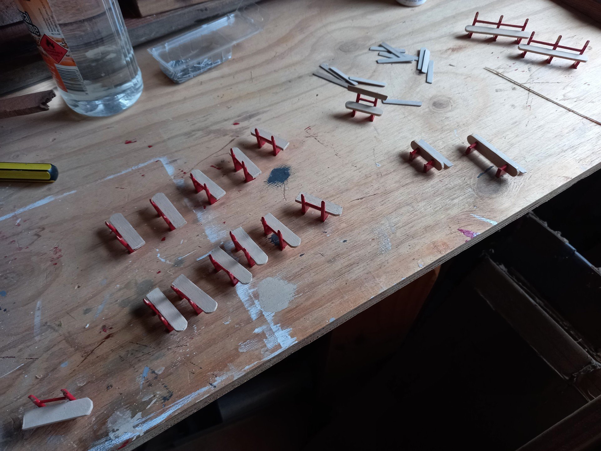
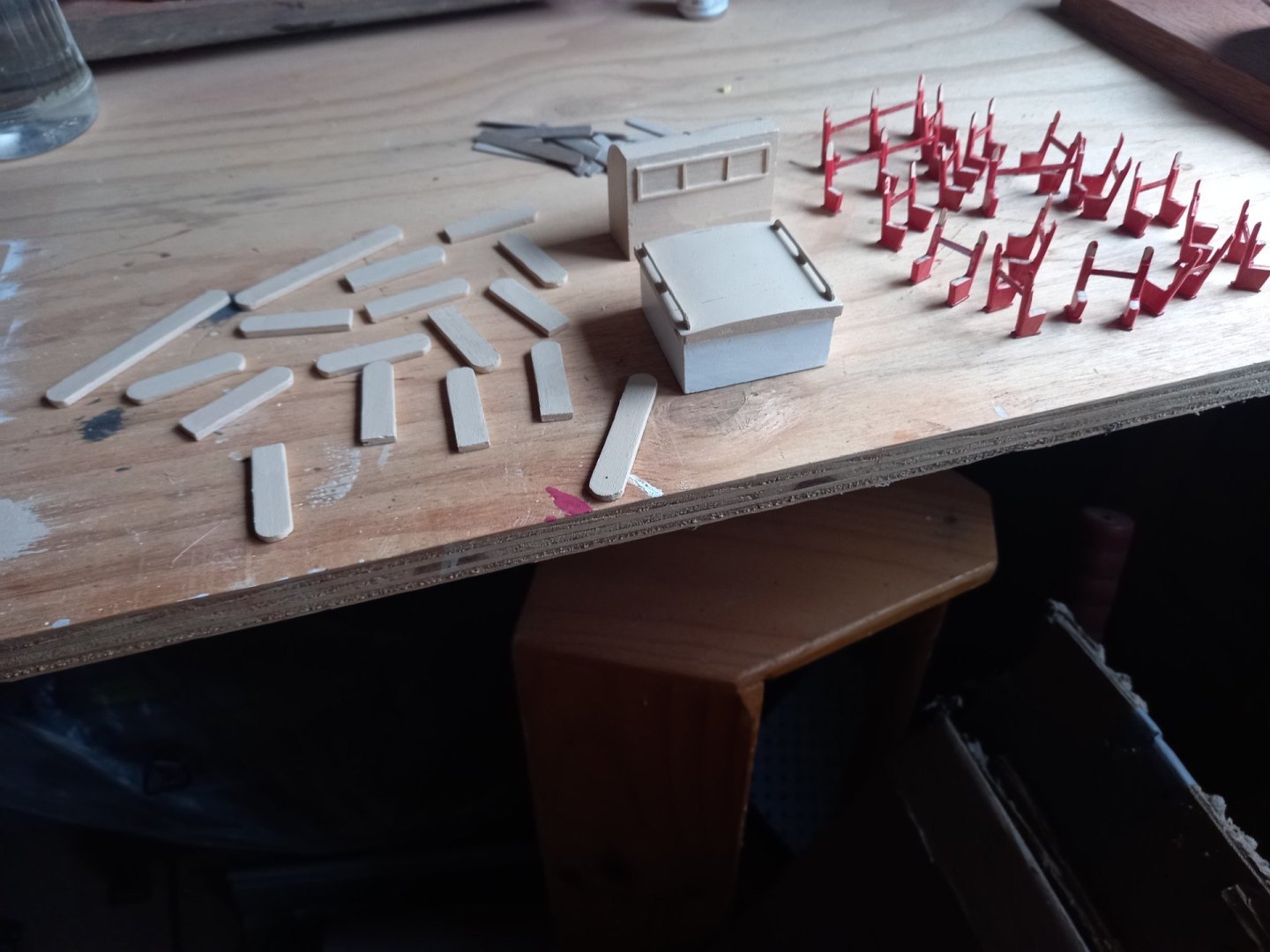
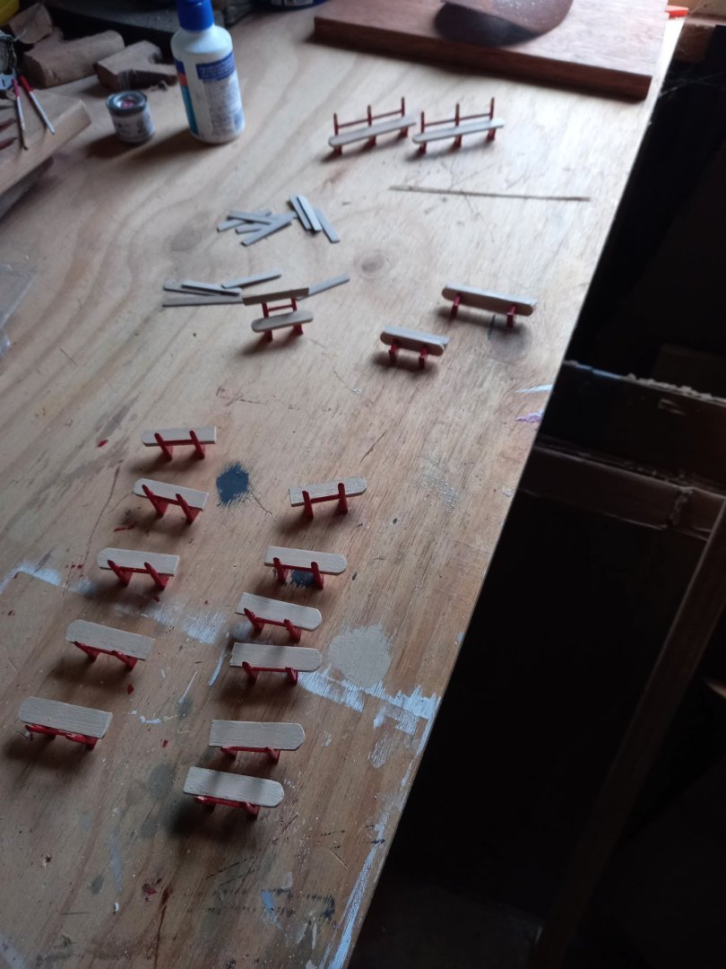
I've been working on the deck furniture - painting the seats and the deck structures and assembling the seats. Still in progress, but these photos should give an idea of how it's going. The thingy that looks like a roll-top desk contains sliding-door compartments for storage, and is also where the wheel is to be mounted. The thingy with handles at the top is also for storage as far as I can make out. And you can see the substructures for the benches (on the right, painted red), the seats (left, cream colour) and the backs of the benches (behind the rolltop desk thingy). Benches in the process of assembly. Note that several of them are asymmetrical - apparently the owners were required to shorten one side of the seat and the backrest because of some regulation or another. More to come in due course . . . Steven

- 110 replies
-
- 10
-
-
- Paddlewheeler
- Ballarat
- (and 3 more)
-
Nice work, mate. Just keep a stiff upper lip and keep on with the good work. Despite all the problems you've encountered, she's looking very good. I hope you have success with working out the rigging details. If not, who's going to be able to tell you what you did was wrong? Steven
- 176 replies
-
- 1
-
-
- la reale de france
- heller
- (and 2 more)
-
Should be an interesting build. I'll pull up a chair. Steven
- 176 replies
-
- 1
-
-
- la reale de france
- heller
- (and 2 more)
-
No worries, mate. It'd make a change from the weather here. Rain, rain and more rain. And cold. Currently 9 degrees Celcius (48F), feels like 6. Good old Ballarat. Steven
- 69 replies
-
- 2
-

-
-
- spanish galleon
- Imai
- (and 1 more)
-
Oh, that's just down the road, then. Only about 250 kilometers (150 miles) Steven
- 69 replies
-
- 1
-
-
- spanish galleon
- Imai
- (and 1 more)