Louie da fly
-
Posts
7,565 -
Joined
-
Last visited
Content Type
Profiles
Forums
Gallery
Events
Everything posted by Louie da fly
-
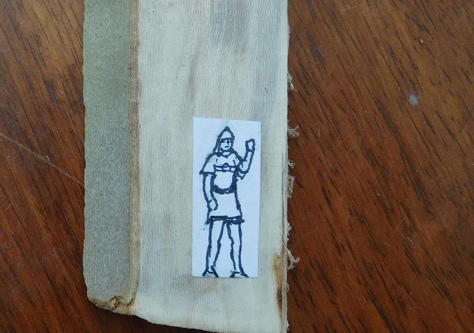
 For one reason and another, | didn’t get a chance to shape the plug for the dromon last weekend, so I’ve got into it again this weekend. Still a work in progress – it’s not bad, but I took a little too much wood away on the second side (just as I did on the first) so I’ve used builder’s filler to build it up again, and I have to wait till tomorrow for it to dry so I can do the final sanding, to get exactly the cross-sections I want. I’ll put up pictures when it’s done. In the meantime, each evening when I get home from work I’ve been making oars. The dromon will have 100 oars in all – 25 per side in both upper and lower banks. I’ve worked out that if I make one oar each evening I’ll have them all done in four months. So far I’ve made 4 upper bank oars and one lower one – only 95 to go! (the photo only shows four, but that was taken this morning - I’ve made another oar since then).As the photo shows, it's very difficult to get all the oars exactly the same. But as they're only 2.5mm (1/10') in diameter at their thickest, I don't think I've done too bad a job. After I discovered how much work is involved in individually marking out each oar before cutting out, I decided to use AutoCad to print them off in bulk onto a sheet of paper so I could cut out and glue groups of oars onto the wood and then saw them out roughly to shape. After that I’ve been using a Stanley knife to trim down each oar, taper the thickness and round it off, smoothing off with files of progressively finer levels of ‘cut’. Today I began to use the power sander to taper the thickness, which cuts out a fair bit of work with the Stanley knife. And now I’ve realised I can short-cut it further if all the oars face the same way, because I can use the sander to roughly taper the thickness of a sheet of wood with a whole lot of them on it before I cut them out, so all the oars are done at the same time. So I’ll change the AutoCad drawing and print off again. The upper oars are somewhat longer than the lower ones, and because the upper oarsmen are above decks, the oars will be visible in their entirety, so they need to be properly shaped all the way along their length. The lower oarsmen are below decks, so the part of the oars that is inboard won’t be visible. So this means that from the fulcrum inboard they don’t have to be ‘oar-shaped’. I’ll probably make some kind of rack to support their inboard ends so they don’t flop around, and shape the ends to slot into the rack. This is something of a bonus, because getting oar handles right is possibly the hardest part of the job. I’ve already made one lower bank oar with a ‘proper’ handle, but I won’t be making more until I’ve decided exactly what to do – I’ll stick to upper oars for the time being. I've drawn and pasted to a piece of wood the first crew member who I'll carve out to pass the time when I get bored with making oars or shaping the hull. He's a stradiote - a marine. He'll be in Byzantine style armour, complete with helmet and sword. In fact all the upper oarsmen served as marines as well, and took the major part in any combat that occurred. It was left to the lower oarsmen to keep the vessel moving when she went into battle.
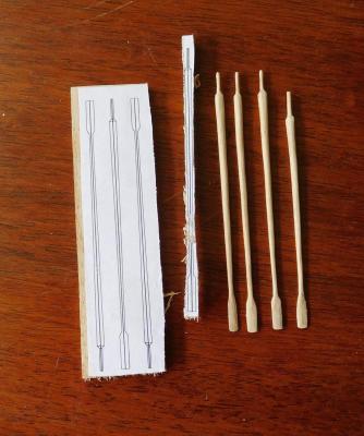

-
I'm really enjoying watching the progress of this wonderful build. I particularly like the precision and attention to detail, particularly with something so small, but also watching the problem-solving is a real education. Steven
- 641 replies
-
- 2
-

-
- greenwich hospital
- barge
- (and 1 more)
-
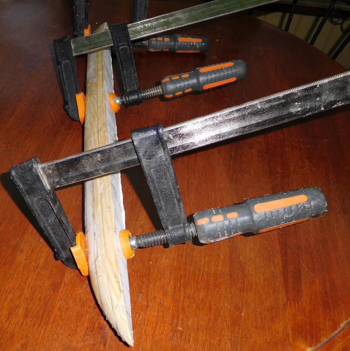
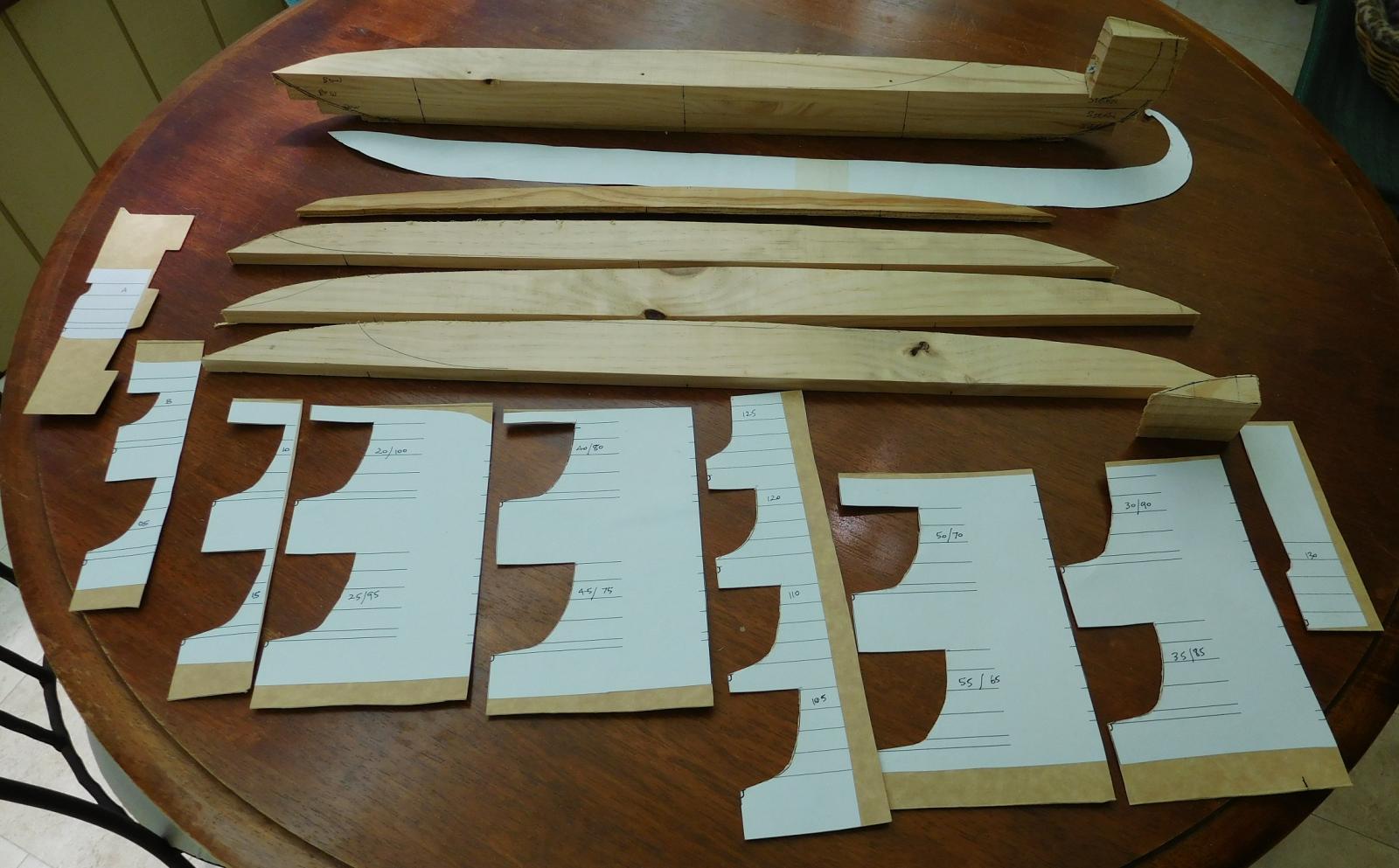
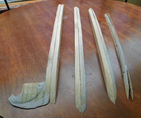
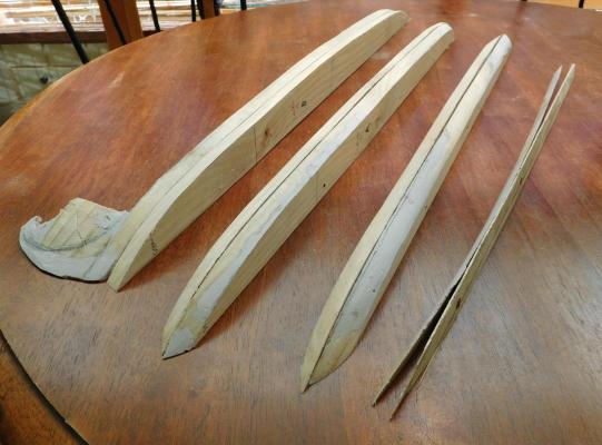
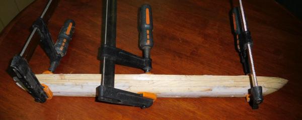
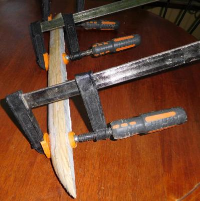
I’ve spent quite a bit of time on the weekend on the plug and it’s almost complete. My idea was to screw the lifts of one half-hull together and shape the half-hull, then take it apart again. Then I’d form up each lift of the second side by putting it back-to-back with its opposite number to make sure the second half mirrored the first. The lifts are 12mm (1/2”) thick pine plank, except for the one at the bottom, which is made of 6mm thick ply. The hull’s cross-section changes shape dramatically about 6mm above the keel, and I decided that this would be the best way to control the change of section. I used a belt sander to take off the excess wood and all went well until I had the first half-hull shaped. I’d cut out a bunch of concave templates of the cross-sections at 1 centimetre intervals to put against the hull to check the shape at each point. It wasn’t too far off, but I discovered I’d sanded a little too much off in places, so I covered the relevant areas with a bit of builder’s filler, waited for it to dry and carefully sanded it until it was the exact shape at each cross-section. Then I hand-sanded the surface (actually I used a file – it seems to work just as well as sandpaper) until it was nice and smooth. Unfortunately, once I’d done that I realised that I’d painted myself into a corner. With the builder’s filler over the joins between the lifts, I couldn’t separate them by simply undoing the screws. So I had to cut through the filler at the joins with a Stanley knife (box cutter), which rather spoiled my nice smooth finish. Anyhow, I’ve now belt-sanded the lifts of the second half roughly to shape using the lifts of the other side as models.There’s a little more shaping to be done where the lifts meet each other, but it’s looking pretty good. However, because the lifts aren’t yet glued together, the bottom lift has started to bend at the ends. It's only made out of 6mm three ply and is sanded right down to nothing at one edge, so it’s a very long thin triangle. I’m not concerned by this, as gluing and tightly clamping all the lifts together will fix it quite easily. I’ve screwed the second side together and it looks ok. Today (Monday) I glued the lifts of one side together, and tomorrow when that’s dry (and the clamps are free again) I’ll do the other side. I’ve also discovered why I couldn’t get the tail to follow the curve I wanted. The sternpost turned out to be not a tight enough curve, so no matter what I did it wouldn’t do what I wanted. It was only a smidgin out – I only had to bring the ends in about half a millimetre (about 1/50 inch) and push the middle of the curve out by about the same amount. I’ve made a new one with a slightly tighter curve and I’ve started refining its shape and working on the first scarph joint, where it joins the keel. Now I’ve fixed that, I’ve found that the ‘tailpiece’ which joins to the sternpost is the right shape to follow the curve, so I don’t need to make a new one. Next weekend I’ll be doing more on the plug and the sternpost. I still need to make the part of the second half that corresponds to the tail and smooth it off. Then I’ll have to cut grooves in the plug for the frames. I’ve marked the positions of the lower oarports to make sure the frames don’t cross them, so I’ll be measuring very carefully to get them in the right places. Once that’s all done I’ll be ready to start making the frames – they’re going to be only 1mm (1/25") square in section, so I’ll have my work cut out for me, particularly as I don’t have a bench saw. However, I’m good mates with the bloke across the road who does have one, and he should be willing to cut my planetree wood into 1mm slices for me. Steven

-
That's a really good discovery, Dick. Adds that extra special something and, I think, adds to the meaning of the model to know who it belonged to. By the way, I notice there are two small copies of the coat of arms at the bottom of his portrait, as well.
-
Thanks for the information, Glenn. Yes that seems pretty clear. I'll have another look at the paper later and see if I can locate those timbers.They really put a lot of thought into these vessels, didn't they? Give my thanks and regards to Cemal. The trouble is that at this stage of the build I'm pretty much committed to the design I have, so I'll be going with a straight keel (though with a very slight downward bow I haven't been able to get rid of). However, what I'm calling the stem and sternposts are curved upward, so maybe I'm closer to the actual design than I thought. Druxey, I'm quite surprised that just squeezing with the fingers is enough. Do you mean you hold it in your fingers till the glue is dry, or do you just push the pieces together and that's enough? I think I might have to hold mine together somehow, as I'm not all that confident in my scarph joints or the straightness of my pieces, especially the troublesome keel. I don't think they'll just lie there together on a flat surface without rolling a little out of position. I don't think it's enough to spoil the model, but after all that work and getting it almost straight I just don't know that trying it again and making another one would produce any better result. I spent the weekend on the plug and I'm pretty happy with it. I'll put photos up in the next day or two. Steven
-
Lovely work, Danny. It's a pleasure to look at and follow. I'll be happy if I can do half as well when it comes to detail. Steven
-
That would be great, Glenn. By the way, Cemal doesn't know me as Louie da Fly (of course). So tell him Steven Lowe says hullo and convey my thanks to him. And also my thanks to you. That model you made of YK4 was very inspirational and helped a lot in formulating my ideas of how a dromon would be. I consider it a privilege to be in touch with the man who built it. Steven
-
That's very interesting, Glenn. Did you get this from the archaeological reports - I don't remember seeing this information in what I've read, but I might have missed it. I'd appreciate being pointed towards where this appears, as I'd like to get the ship as close as possible to what the archaeological evidence shows. Best, Steven PS: I see you live in College Station Texas - do you work at TAMU? If you know Cemal Pulak and you see him, say hullo to him for me and tell him the dromon build is at last under way. He's been very helpful - and generous - with information, and I'm very grateful for his assistance.
-
I don't know, Dick. It'd probably be pretty hard to work it out anyway. The Yenikapi hulls were all incomplete and in pieces - if a keel was curved it might have been by design or because of the twisting and bending effects of being underground for so long. (Oh, and it's an earthquake zone.) I think it's amazing that they were in no worse condition than they were. But to answer your question, I haven't seen anything which mentions whether the keels were straight or curved. Best wishes, Steven
-
Thanks, Druxey. I'm not terribly happy with the joints between the sternpost and the 'tail' - in fact I'm thinking of making them again - the current pieces were cut a little wrongly and so I can't make a joint that will enable them to follow the curve I want in the tail. And if I do that, perhaps I'll have another try at the keel as well - it still bows downward a little in the middle and it's not the same colour all the way along its length. Maybe I can recycle it to make the keelson. I know PVA glue works best when the joint is clamped together. Do you clamp your scarph joints? I was thinking of using an elastic band but I don't trust them much - they tend to mis-align things too easily. Or perhaps I could wrap the joint in thread while it dries? Any advice gratefully received. Best, Steven
-
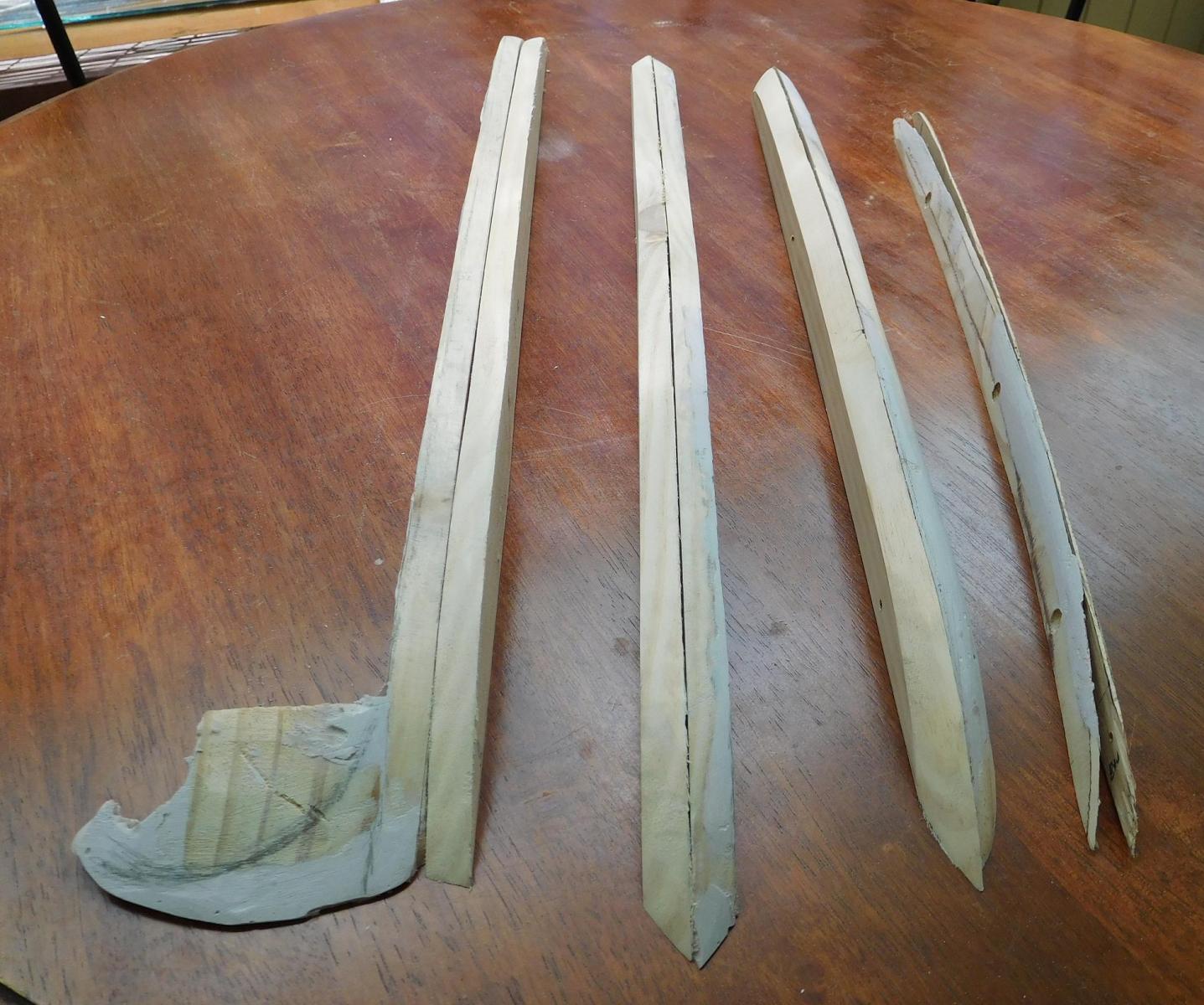
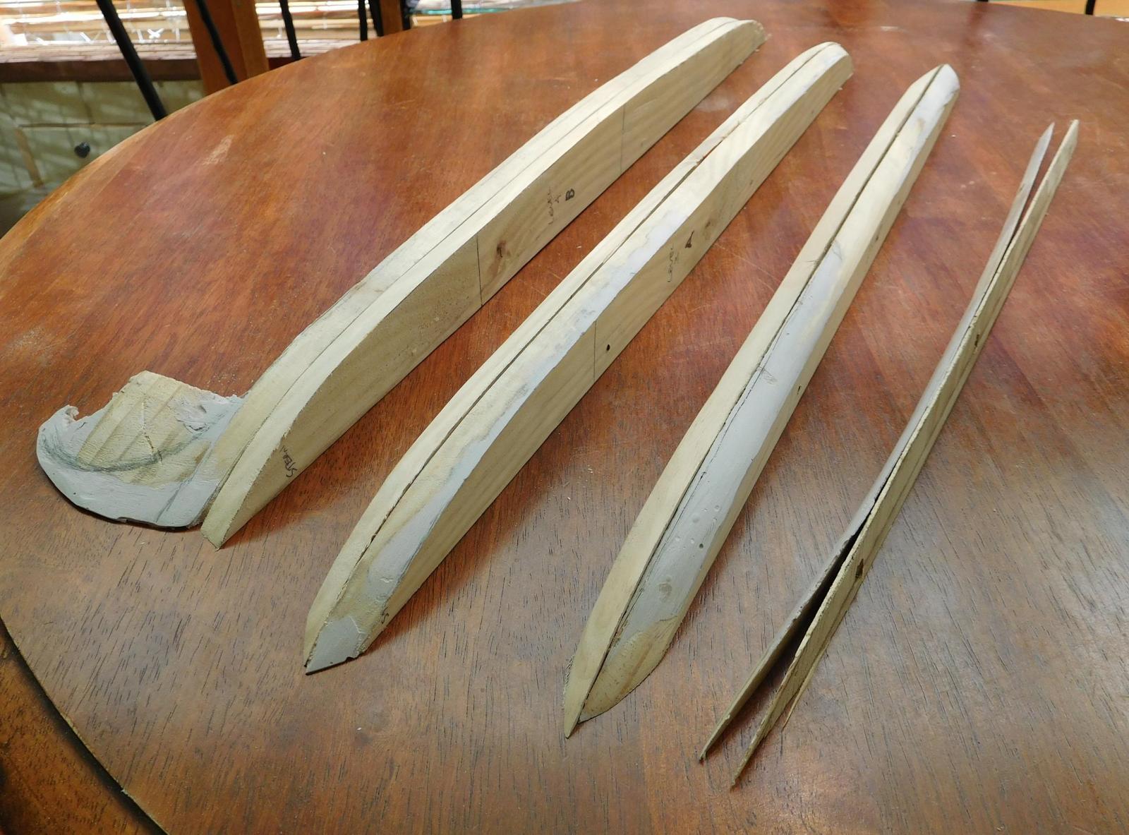
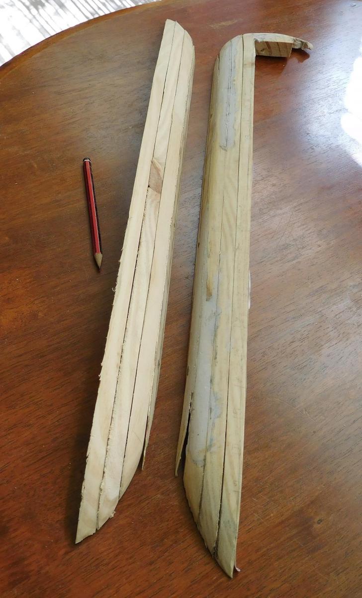
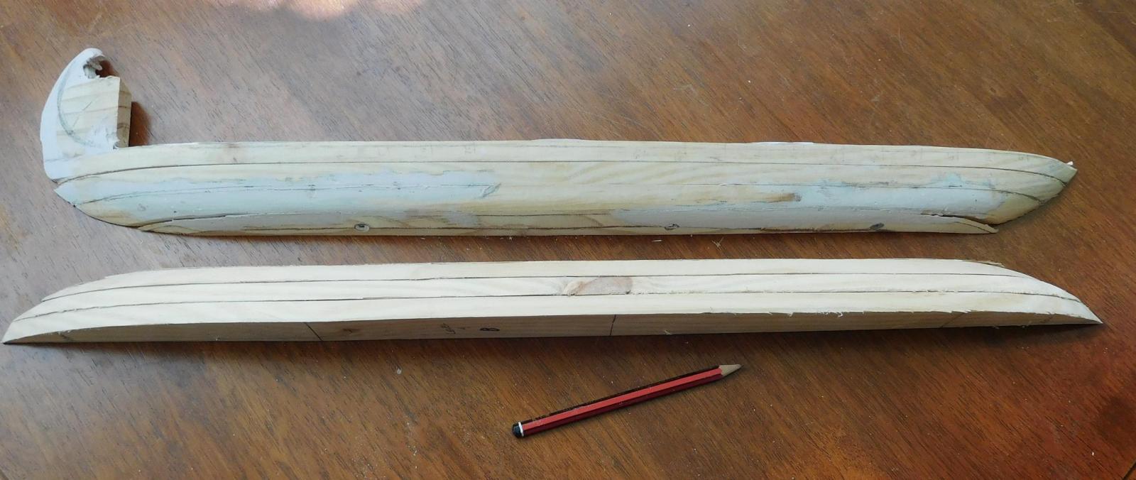
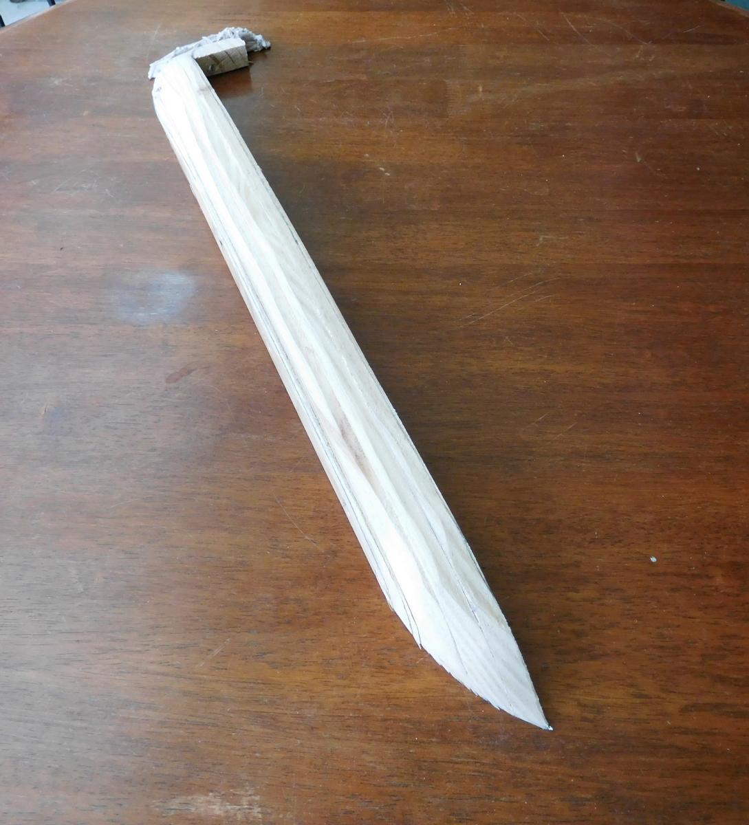
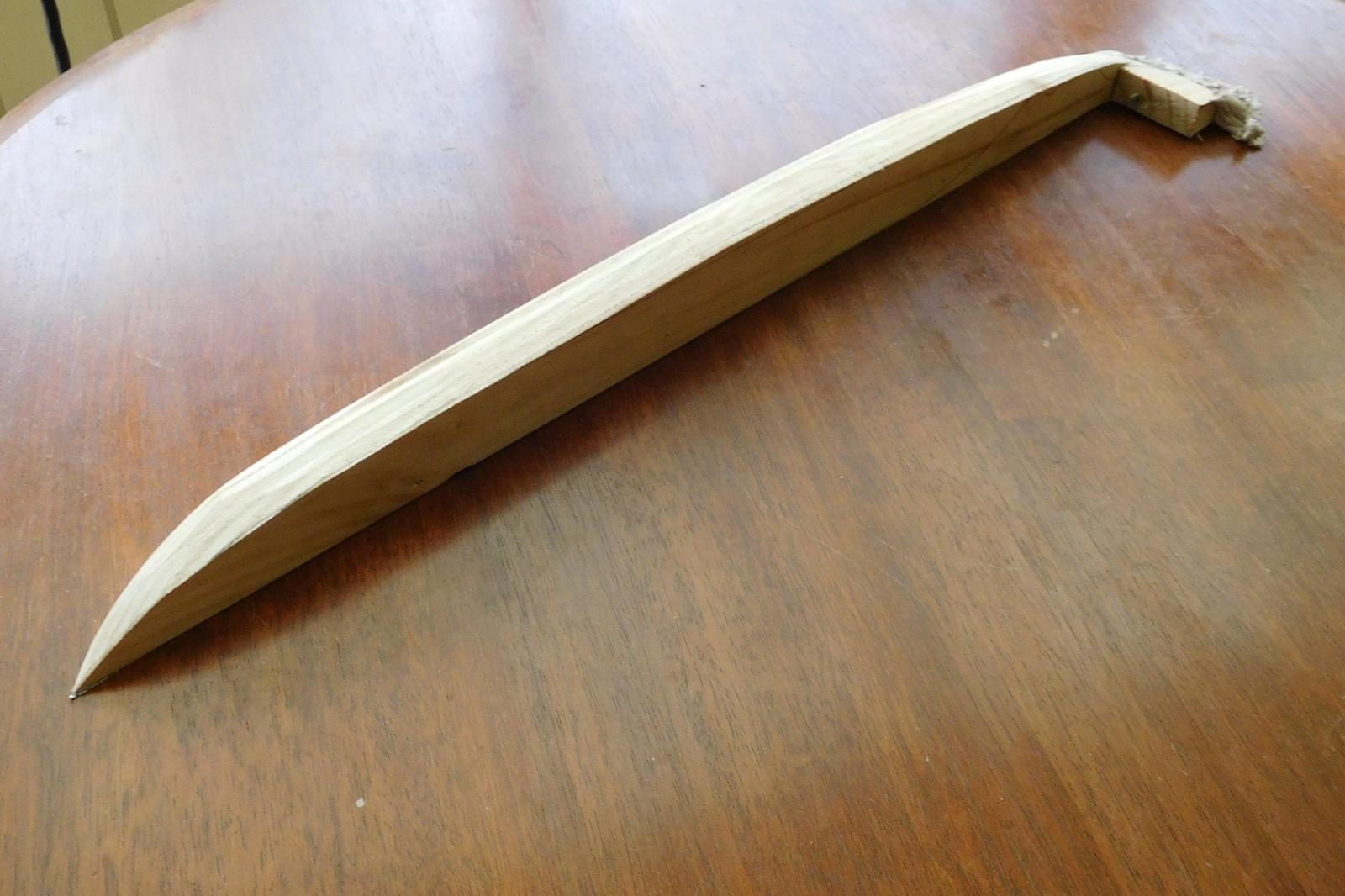
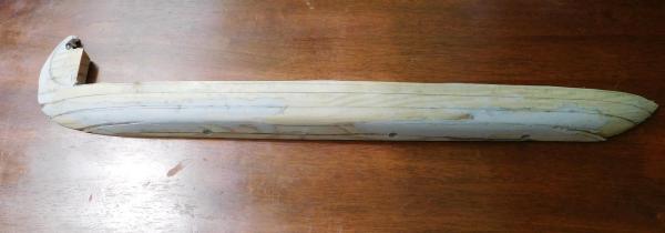
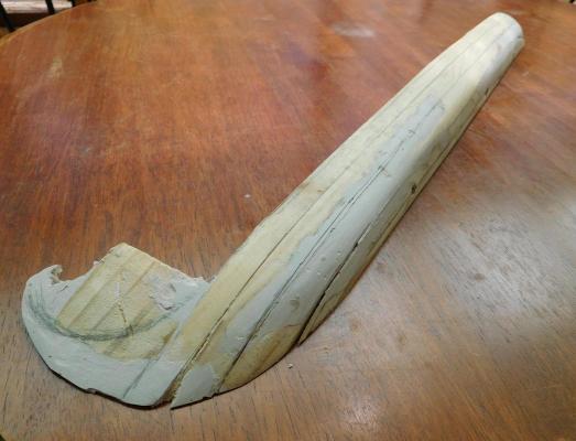
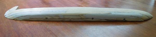
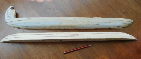
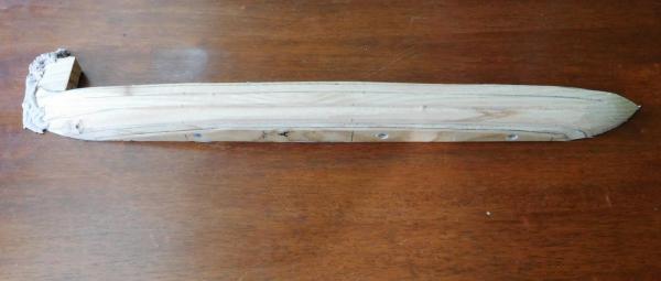
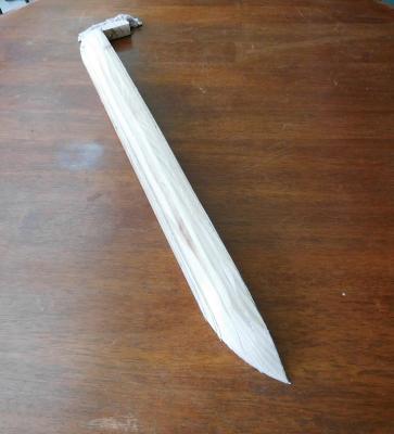
Well, here are the photos as of Sunday afternoon. I've roughly shaped one half of the plug - more still to be done; the hard bit, getting it the same shape as the cross-sections say it should be. I learnt something - don't use an electric planer to "just trim a bit off the stern" - it takes great bites out of the wood and I ended up losing a fair bit of the 'tail'. So I've added some builder's filler to make it up to shape again. And from now on I only use the sander. Next weekend I'll sand it properly to shape on one side and then begin on the other half if I have time. I still have to get the scarph joint between the sternpost and the 'tail' shaped properly - it's giving me some problems getting it all to mesh precisely and have the tail go up at the right angle. I think I'll have to make some kind of jig to hold it all while I'm gluing the keel, stempost, sternpost and tail pieces together. Does anyone have any advice for doing this successfully? I have to admit I'm not looking forward to it - too much chance of messing up after all that work. Maybe I should be gluing one joint at a time? I don't know. Steven

-
That looks so good, Dick. She's really progressing well. Steven
-
Thanks, Druxey. I've done a bit more but now the weekend is over, it's back to work for another week. I'll try to put up some update photos this evening, then it'll be a gap till next weekend. Carl, I don't think there was any Viking influence on Byzantine ship design -If anything it'd be the other way. But I really think it's just a case of convergent evolution. Steven
-
This is a beautiful piece of work, Dan. I've only just come on board and I'm very impressed by the precision of the craftsmanship and the detail. And the cutaways are a lovely touch. Steven
-
That's not surprising, Carl. Any ship that's to be rowed with speed as its objective is likely to have pretty much the same kind of shape - long and narrow. One thing I thought was interesting is the gentle curve of the outline (seen from above). Apparently Renaissance and Ancient galleys had pretty much straight, parallel sides. But the Byzantine galleys found at Yenikapi definitely swelled gently outwards from both ends toward the centre, rather like the Viking ships of the same period. Steven
-
Just cut the lifts for the plug. As I really don't have much confidence that I'd be able to get both sides the same by eye, I've screwed together the lifts for one side and I'll smooth this side off, using the sections I've cut out of cardboard to check that I've got the shape right as I go. Once I'm happy with this side, I'll pull it apart again and use it as a template to modify the lifts of the other side. That way I've got the best chance of getting the shape of the hull symmetrical. Wish me luck!

-
A beautiful build of a beautiful vessel. What more can I say? Steven
- 641 replies
-
- 5
-
-
- greenwich hospital
- barge
- (and 1 more)
-
Druxey, the frames for my dromon will be a bit over double the thickness in both dimensions compared with yours. Do you think your 'wet bending' technique would work for them as well, or should I use heat as well? Steven
- 641 replies
-
- 1
-
-
- greenwich hospital
- barge
- (and 1 more)
-
That makes a lot of sense, Dick. I think the "combat" idea is more wishful thinking than based on any sort of evidence. Steven
-
Nice work, Dick (as usual). Landstro"m's book states that the grapnel was for grappling other ships in battle, but I don't know that this was based on anything other than supposition. However, the Anthony Roll depiction of the Great Harry at the very least, shows her with not only a grapnel on a chain hanging on the bowsprit, but also double-hooked yard arms. This was after all a time of transition from boarding and hand-to-hand fighting to longer distance combat with the big guns. So perhaps the grapnel is indeed for grappling other ships. Steven PS: Where did you get that lovely piece of chain?
-
Such a beautiful vessel and so expertly put together. You're an inspiration to us all, Druxey. Steven
- 641 replies
-
- 2
-
-
- greenwich hospital
- barge
- (and 1 more)
-
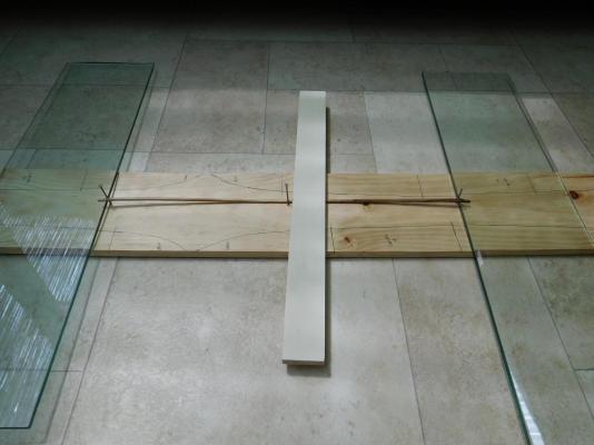
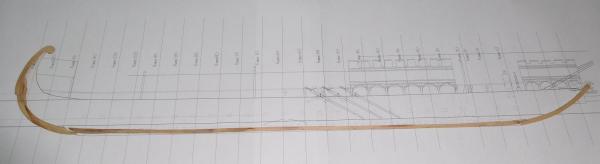
Thanks, Druxey. As far as I can see the grain is pretty straight, and I tried to choose as straight a grain as I could find, but I agree it will go where it wants to go. I think I'll pin it to my plug the same way you did with yours - it looks like a very good way to go. Mark, it's European plane wood, the same as the keels of several of the Yenikapi galeai were made from. I wanted to keep it as close as possible to the original; the other Yenikapi galeai had oak keels and I could have used that instead, but I've never worked with plane and I wanted to see how it went. Fortunately, Ballarat has street trees of both kinds (as well as ash, elm and other European varieties introduced by the settlers in the 19th century) and I'm able to get a lot of timber from loppings. By the way, the jig seems to have worked pretty well. I may have to do a bit of final tweaking, but I'm pretty happy with the result. Next I'll tidy up my scarph joints between keel and the stem and sternposts, and cut out the pieces for the plug. I'm looking forward to it Steven
-
A very ad hoc jig for straightening the keel in two dimensions at once. A nail at each end and one in the middle to bend the keel around in a horizontal direction, plus a sheet of glass to lift each end of the keel and a piece of wood to weigh it down in the middle. We'll see if it works . . . Steven