HOLIDAY DONATION DRIVE - SUPPORT MSW - DO YOUR PART TO KEEP THIS GREAT FORUM GOING! (Only 72 donations so far out of 49,000 members - Can we at least get 100? C'mon guys!)
×


Louie da fly
-
Posts
7,989 -
Joined
-
Last visited
Content Type
Profiles
Forums
Gallery
Events
Everything posted by Louie da fly
-
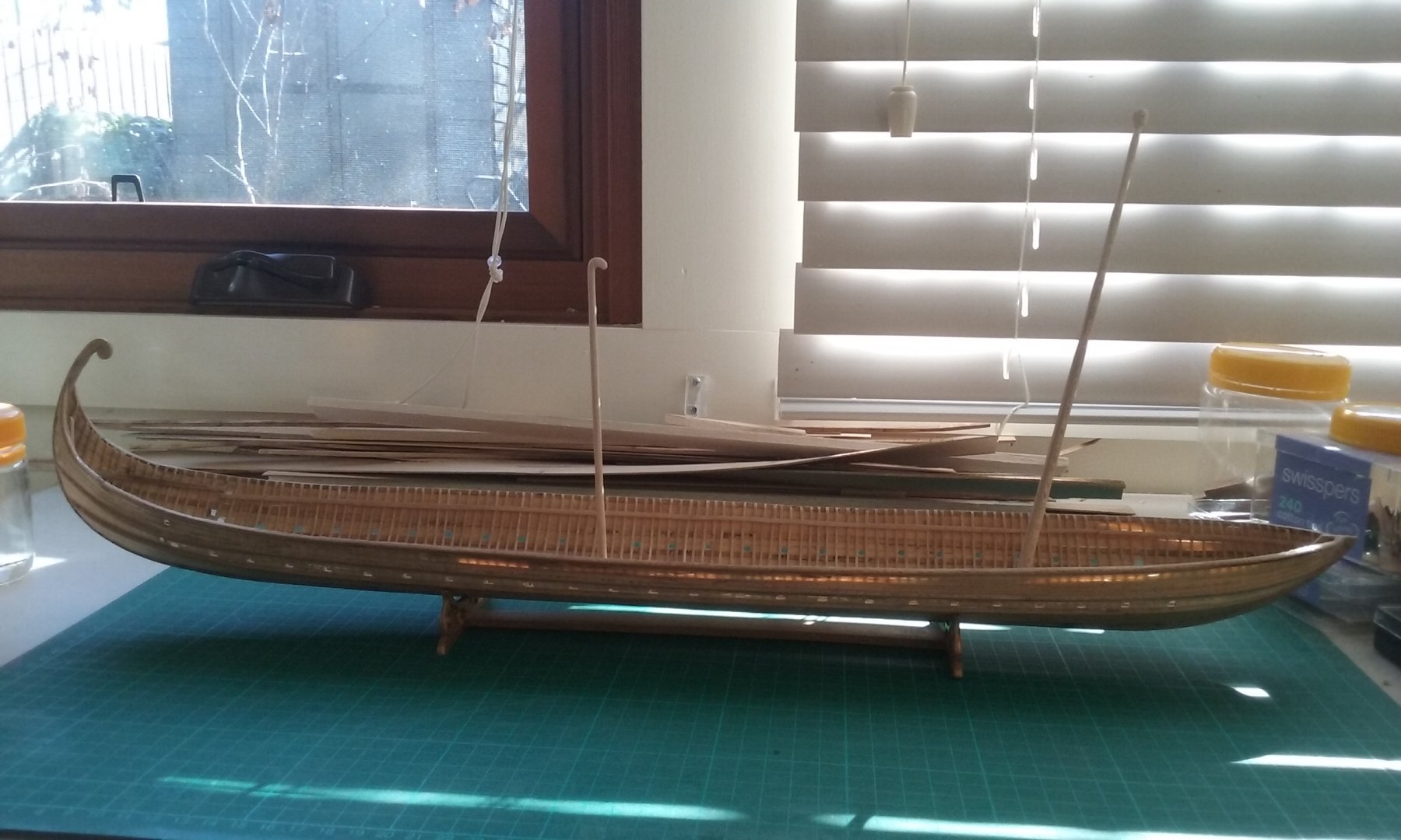
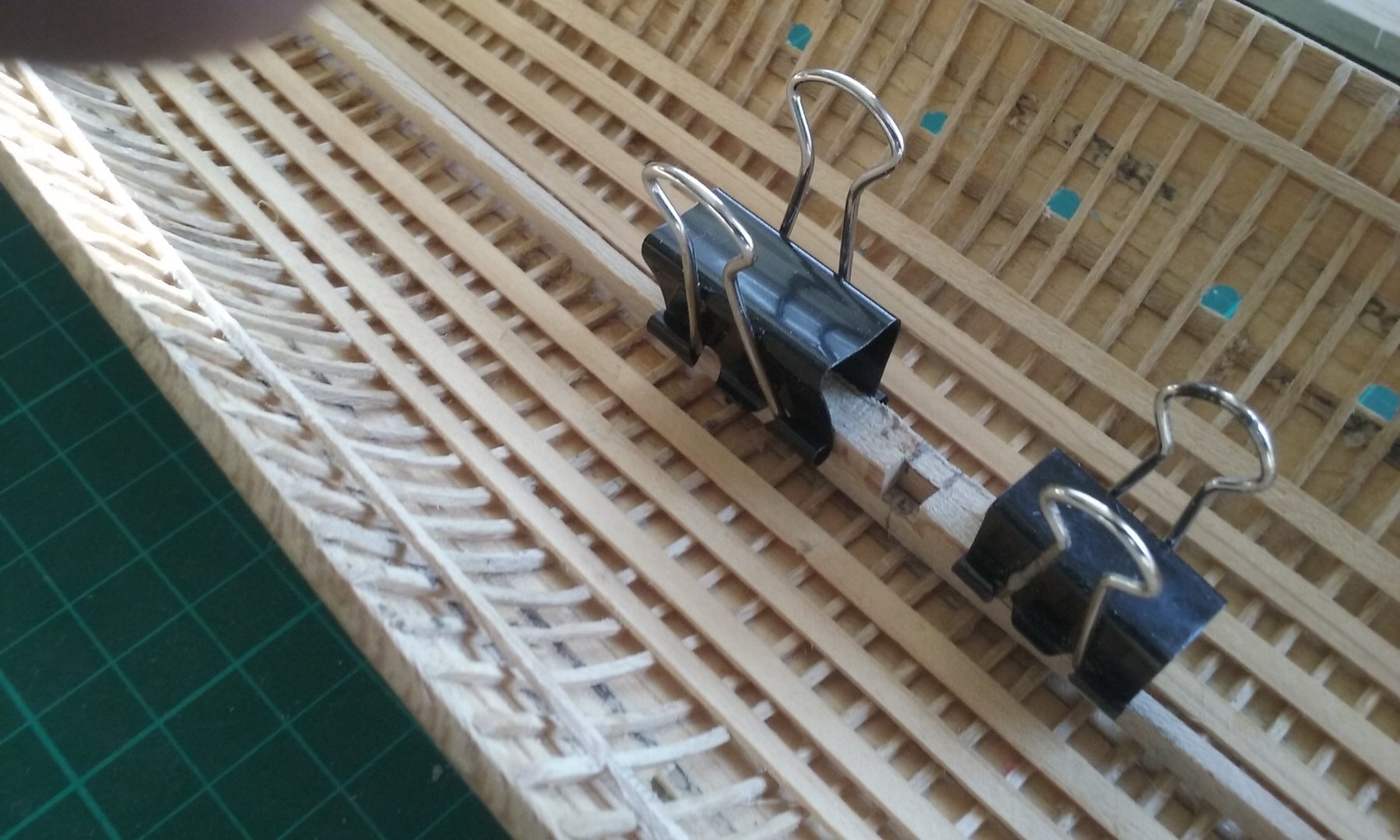
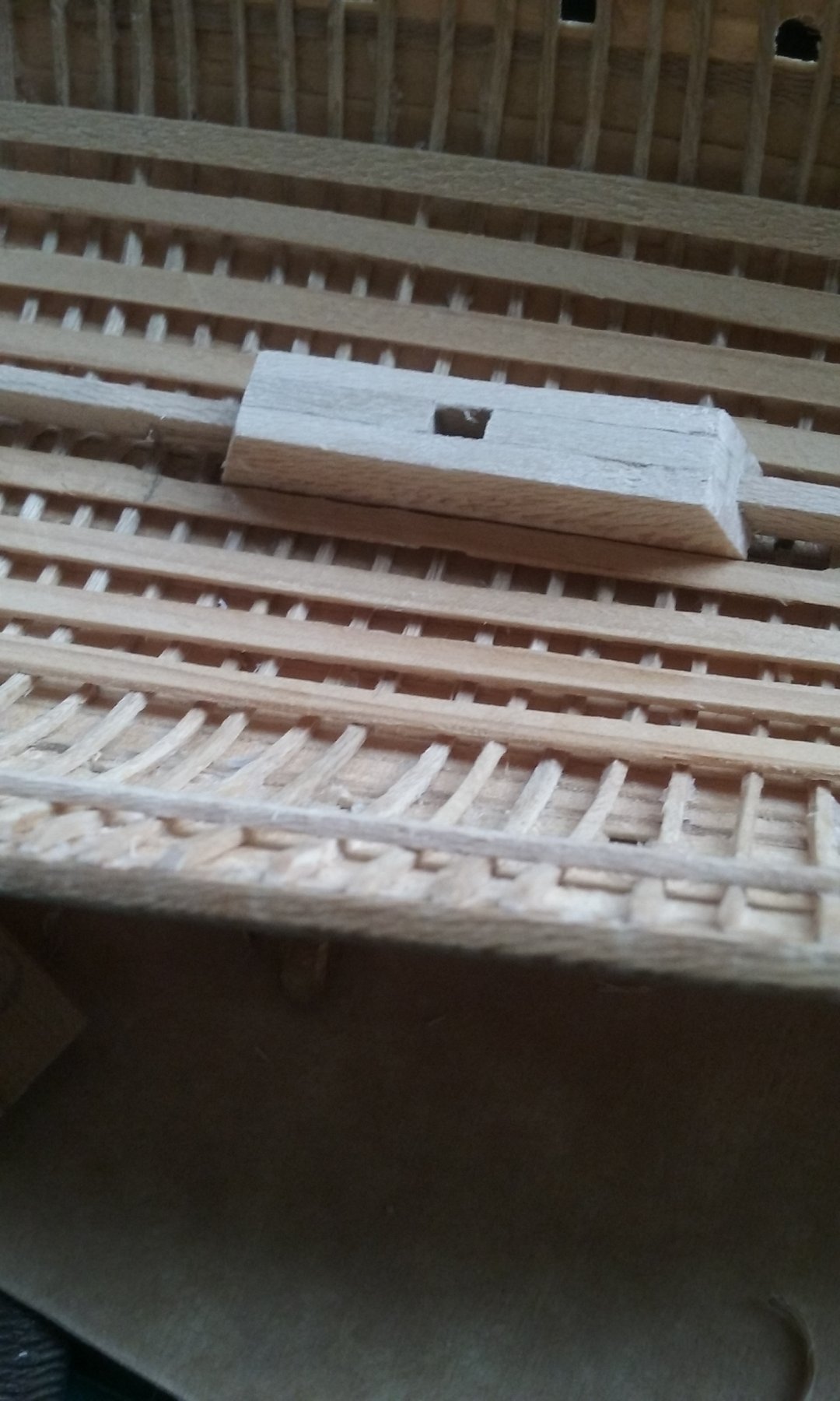
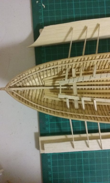
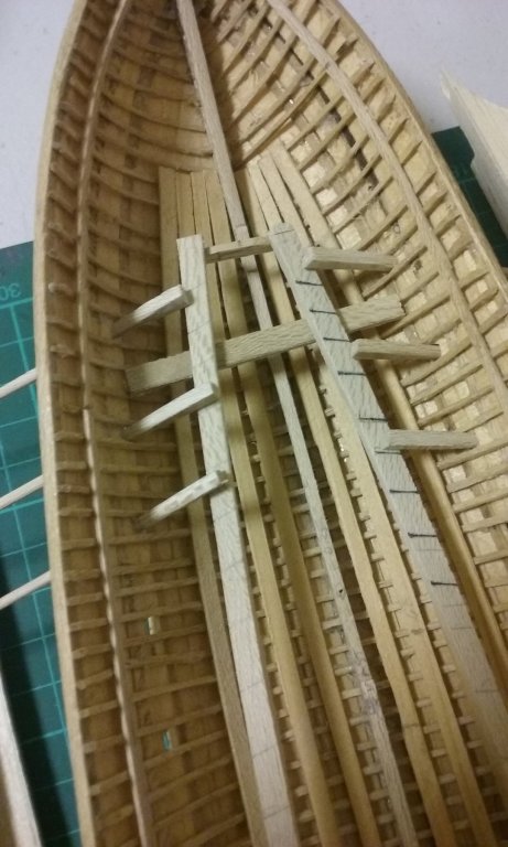
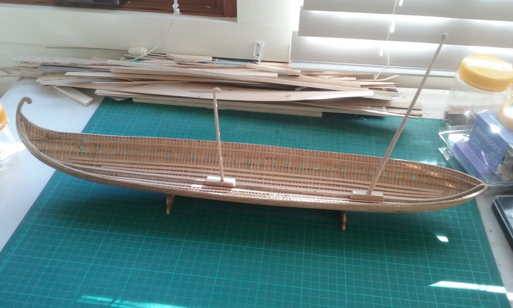
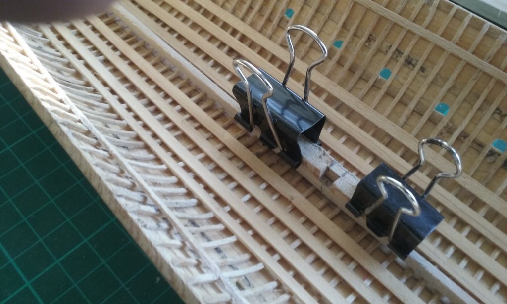
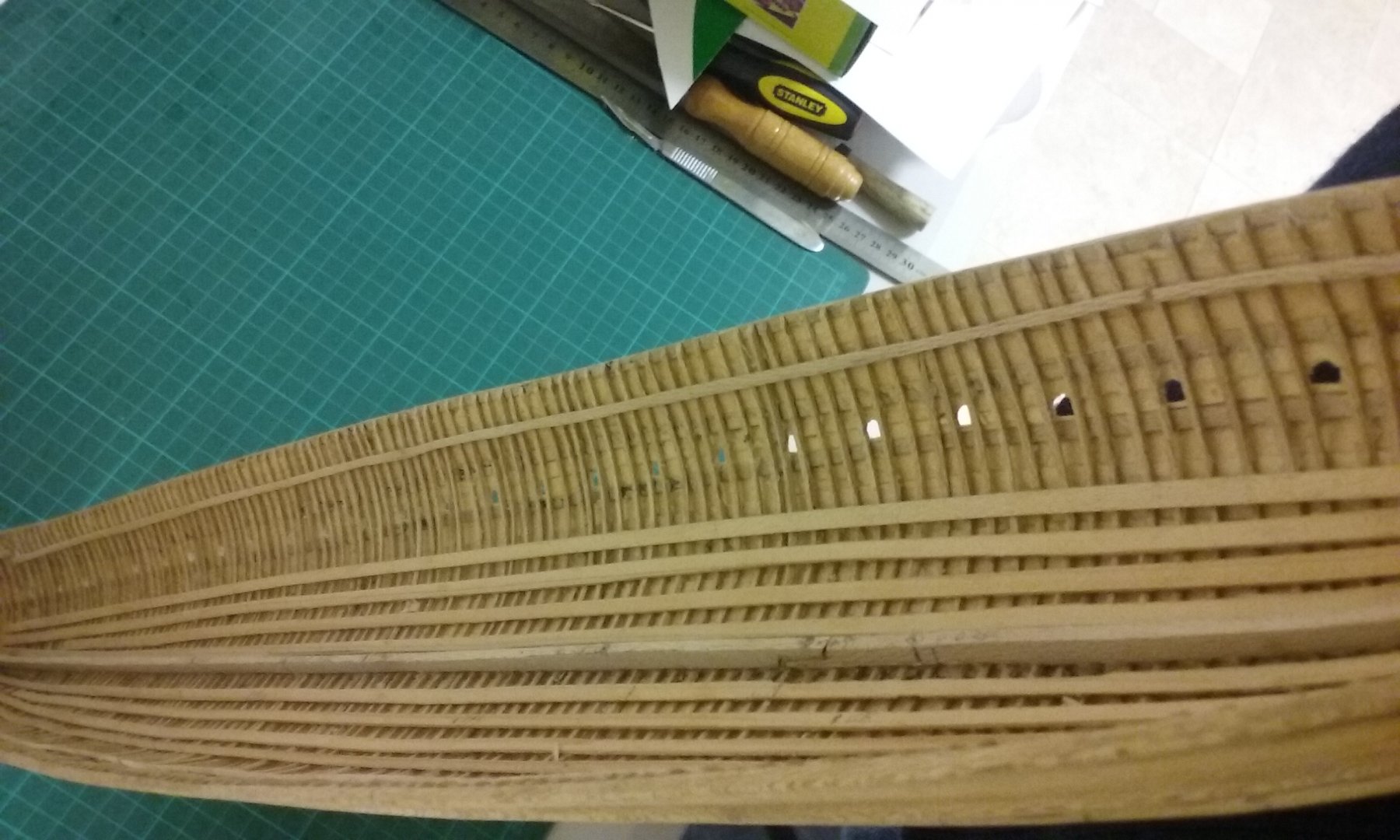
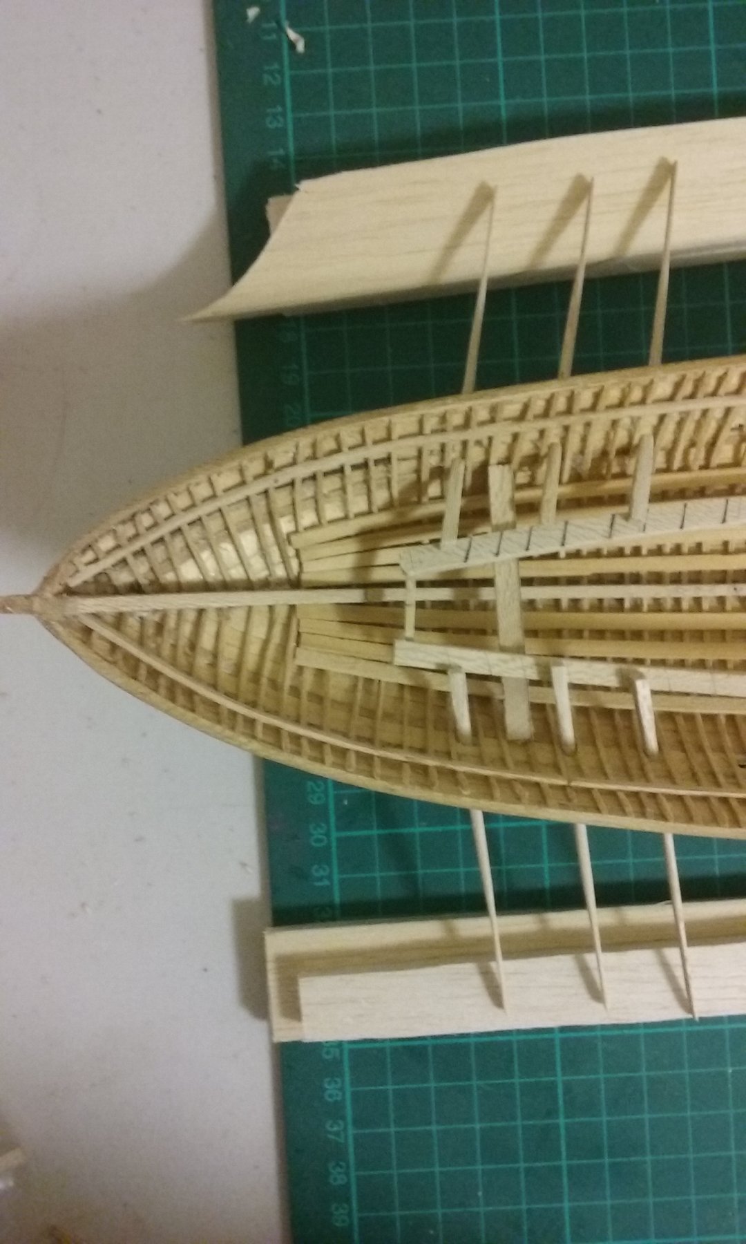
 I've done a preliminary fitting for the support system I'll be using for the lower oars, to see if it will work. A number of cross-members hold at the correct height a frame with a series of lines all at the same angle, as guides for the oars. The oars go through the oarports with the inner end resting on the frame and the outer end resting on a raised plane (currently two thicknesses of balsa wood) to simulate water level. I've done my best to get all the oars as close to identical as possible, so they'll all be at the same angle vertically when they rest on the frame. Also, they'll be interchangeable so it doesn't matter which one goes where. The other quantity that has to be kept constant is how far the oars poke out from the hull, which is done by simply drawing a pencil line around the circumference of each oar at the point it goes through the oarport. I've only tried it with three pairs of oars so far, but it looks like it will work. Now to get it all done properly, with everything lined up and glued in place. As I mentioned before I won't be putting the oars in till later on in the build so they don't get damaged while I'm working on other parts of the ship. The two mast steps are still in progress - I'm making them like the ones found in the Yenikapi ships. Though they're more complicated than my original version I think it's good to do it the way it was done back in the day if at all possible. The blocking piece is shown above the two mast steps. Sorry about the photo quality. At some point I have to correct the line of the beam shelf - it's a bit wonky and has to be made into a smooth line, or the deck beams - and the deck itself - will also be wonky. As can be seen in the photos, the line wobbles very slightly all along its length. As the beam shelf so narrow and flexible, I can probably correct it by cutting it away from the frames at the offending places and re-glueing it in the correct position. If not, I'll have to cut and fill till it's correct. Steven

-
So it's the millimetre rule you're working from? Not the series of vertical lines drawn on the background sheet? Steven
- 263 replies
-
- 2
-

-
- nave tonda
- round ship
- (and 2 more)
-
That's a really nice jig, Dick. Simple and effective. As you're moving only one side of the jig and keeping the other side static, I take it you've arranged the graduated distances on the background to compensate for the lack of symmetry. Are the second two photos above identical ? I can't see the difference between them. Steven
- 263 replies
-
- 1
-
-
- nave tonda
- round ship
- (and 2 more)
-
That's a good reason to go two-masted, Mark. Galleys in general are not too stable. I think sail would be preferable while journeying - assuming the wind was in the right direction, so the ship wouldn't heel over too much. Oars definitely under battle conditions - in fact the masts were lowered and stowed. For maneuvrability and also to remove overhead hazards. Steven
-
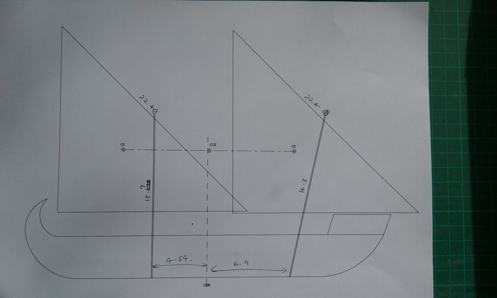
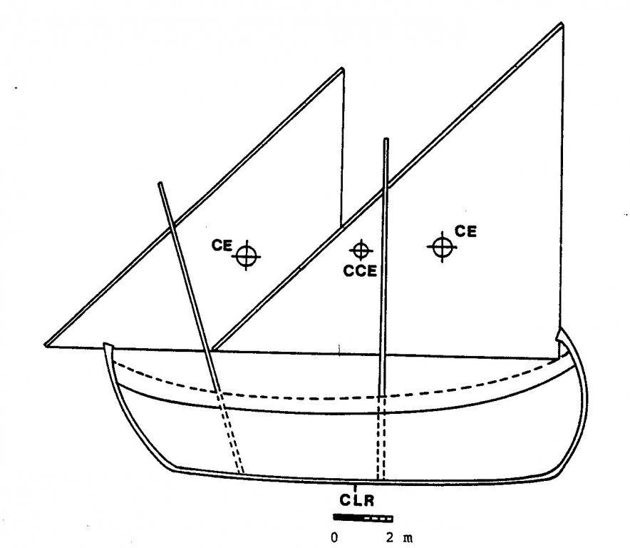
Mark, the single mast cE is about 2.2 metres (7 feet) taller than the double - the difference between 9.4 and 7.2 metres above the bottom of the ship - about 30% higher. Don't know how much difference that would make. Steven
-
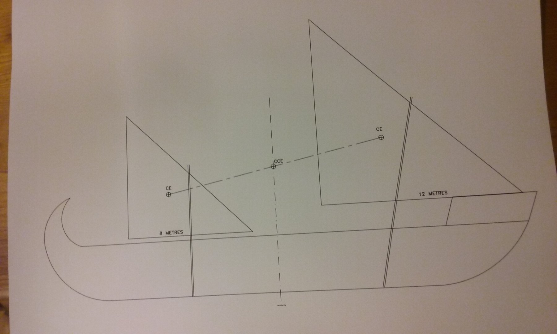
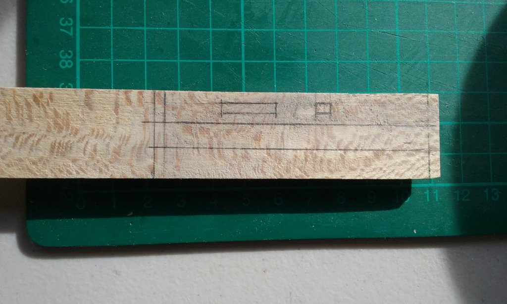
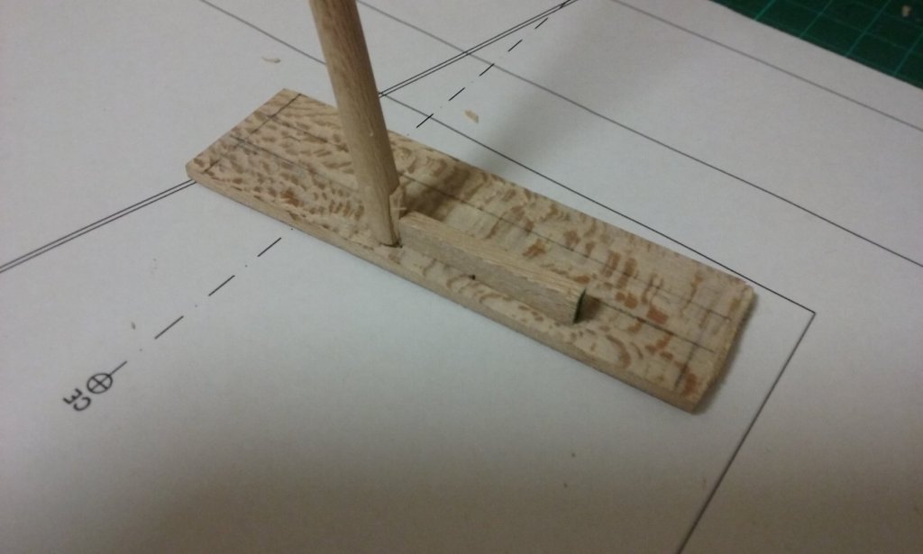
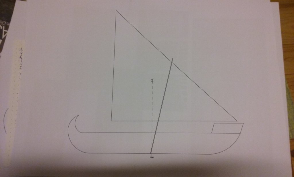
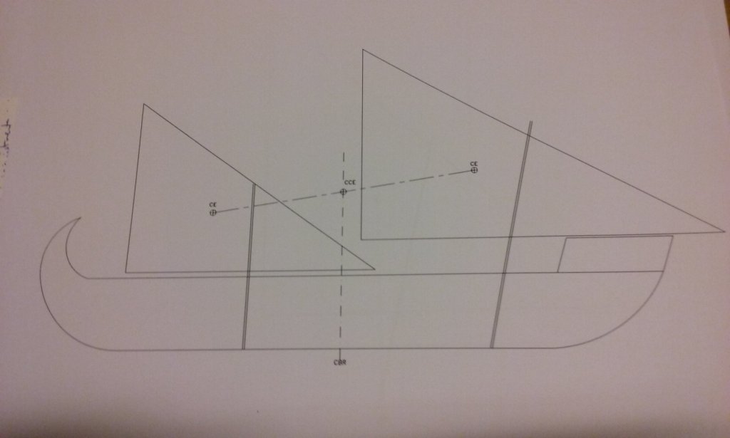
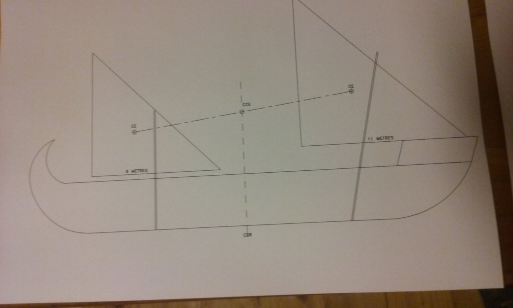
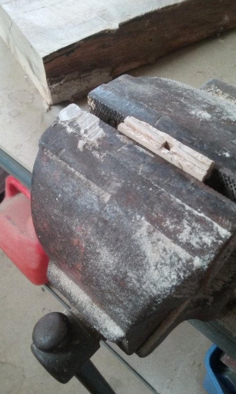
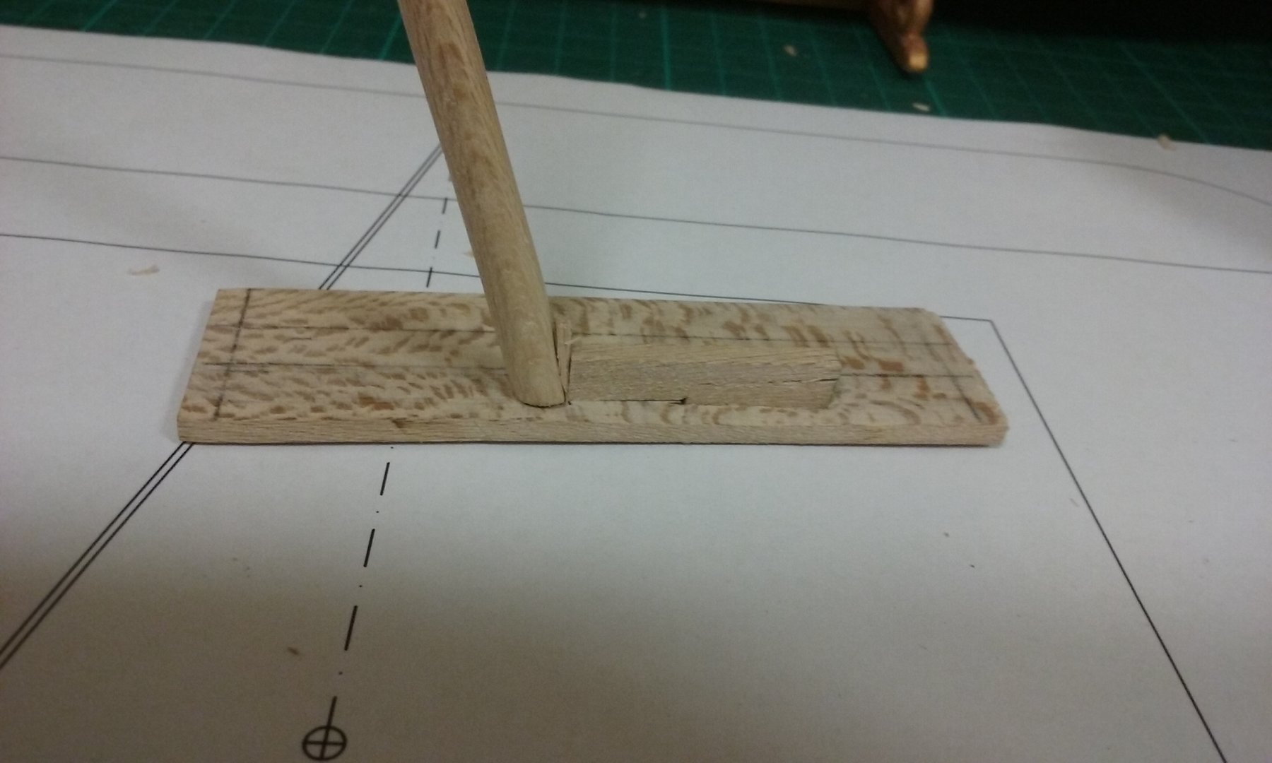
Here are the sail plans I've arrived at - I still haven't decided to go one or two-masted, but both look better than previous versions. The dimensions no longer tie in with those of Age of the Dromon - I've decided that a gap of 200-300 years and different shipbuilding traditions, plus the different form of the two types of ship are enough to discount the Sicilian ships as a source of information. Instead, I'm going with size and placement of sail(s) to achieve the position of Centre of Effort needed to make a lateener sail properly, based on the theory outlined on the previous page of this build log. I've also made a prototype of the Byzantine mast step assembly shown in my reconstruction diagram above. I did this in a hurry and in a poor light, so it's a bit rough. To put in the model I'll do a better job and make it complete - cutting it to width and with side pieces to hold it on the keelson. But it seems to work! Steven


-
Makes sense, Dick. The narrowing of the hull gets greater in a nice smooth curve as you approach the bow and stern. Presumably the same with the rise of floors etc. Clever. Steven
- 263 replies
-
- 3
-
-
- nave tonda
- round ship
- (and 2 more)
-
Oh yes, I knew what the words meant - just don't know the ins and outs of the technique. Steven
- 263 replies
-
- 3
-
-
- nave tonda
- round ship
- (and 2 more)
-
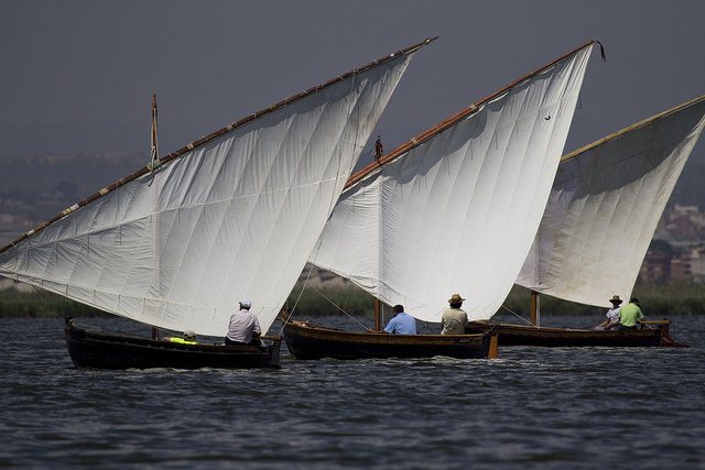
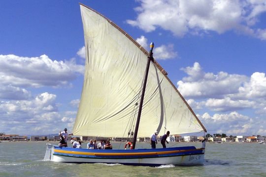
That makes sense, though I thought it might also affect the performance of the sail (messes with the aerofoil shape). I expect in large, state-owned ships they'd have taken the trouble to move the end of the yard to the other side of the mast whenever they tacked, as shown in the diagrams on the first page of this thread. Sporting sailors probably don't have to worry about it so much because they don't use their boats much. However, the skipper of the caravel replica that sails around the coast in our region says he does it "the way the Arabs do" - without changing sides when he tacks. A lot less hassle, but it does have the downside of chafing. Steven
-
Just learnt something. I'd thought than on all lateen sails the halyard attached to the centre of the yard. Certainly a lot of them seem to be this way in contemporary pictures, but if you look at the link http://forum.woodenboat.com/showthread.php?156203-Lateen you can see lateens with what I'd have thought was a very unbalanced set-up. Oh, and some nice footage of lateeners under sail. Having the mast to leeward of the sail (so it's blown against the mast) doesn't seem to be such a problem after all. A pity there isn't any footage of boats sailing under lateen alone, without headsails (or booms, as some modern so-called "lateens" are). Steven
-
Very interesting, Carl. I haven't come across this one before. Certainly lateen rigged, and the "wings" at the stern are thought to hold a crosspiece which supports the yard when it's not in use. The hull is very unusual. I wonder where they got the design from? It doesn't look like anything I've seen in contemporary pictures. But there's plenty of stuff out there I've never seen. Steven
-
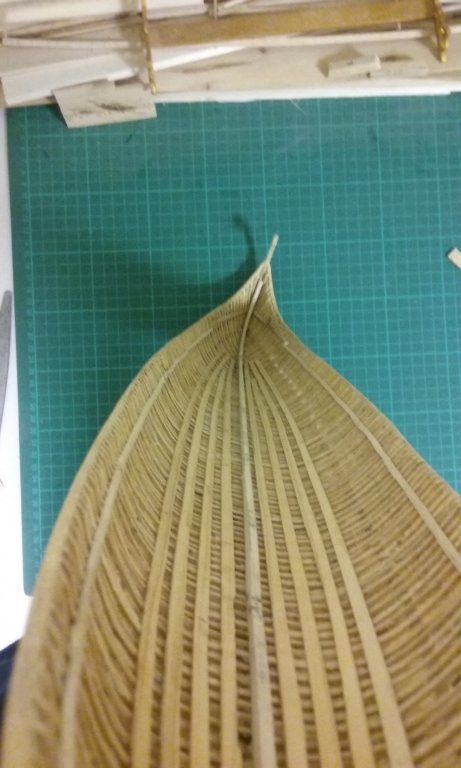
Nice work, Goetzi. Coming together well. Yes, almost all the forecastles I've seen in contemporary representations from this period seem to come to a sharp point at the bow - at least the ones that can be seen, whether they be from the Mediterranean or northern Europe in the region including the Hanse ports. Steven
-
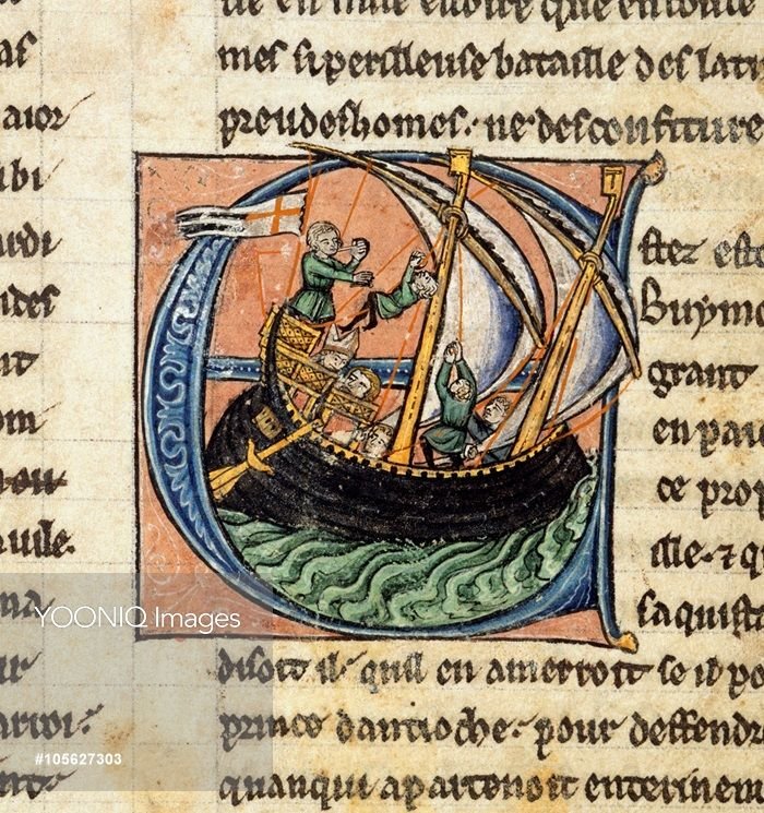
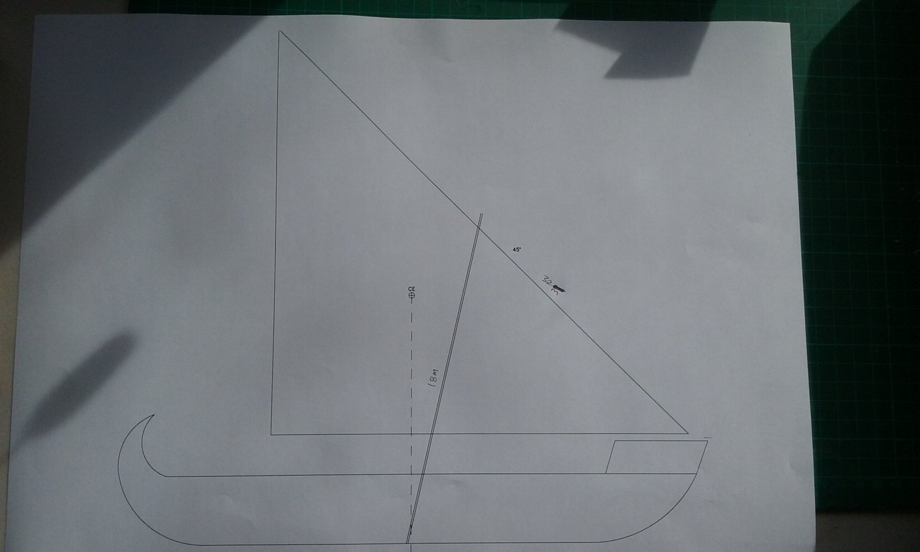
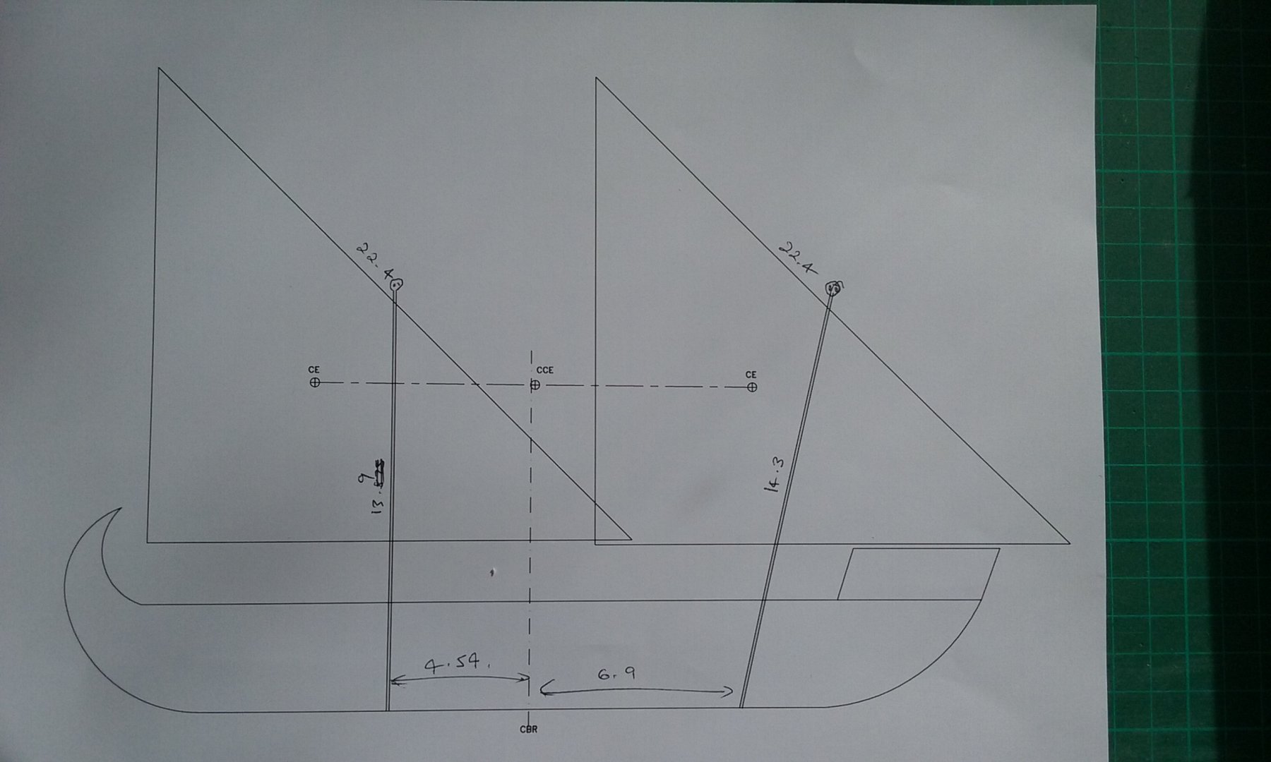
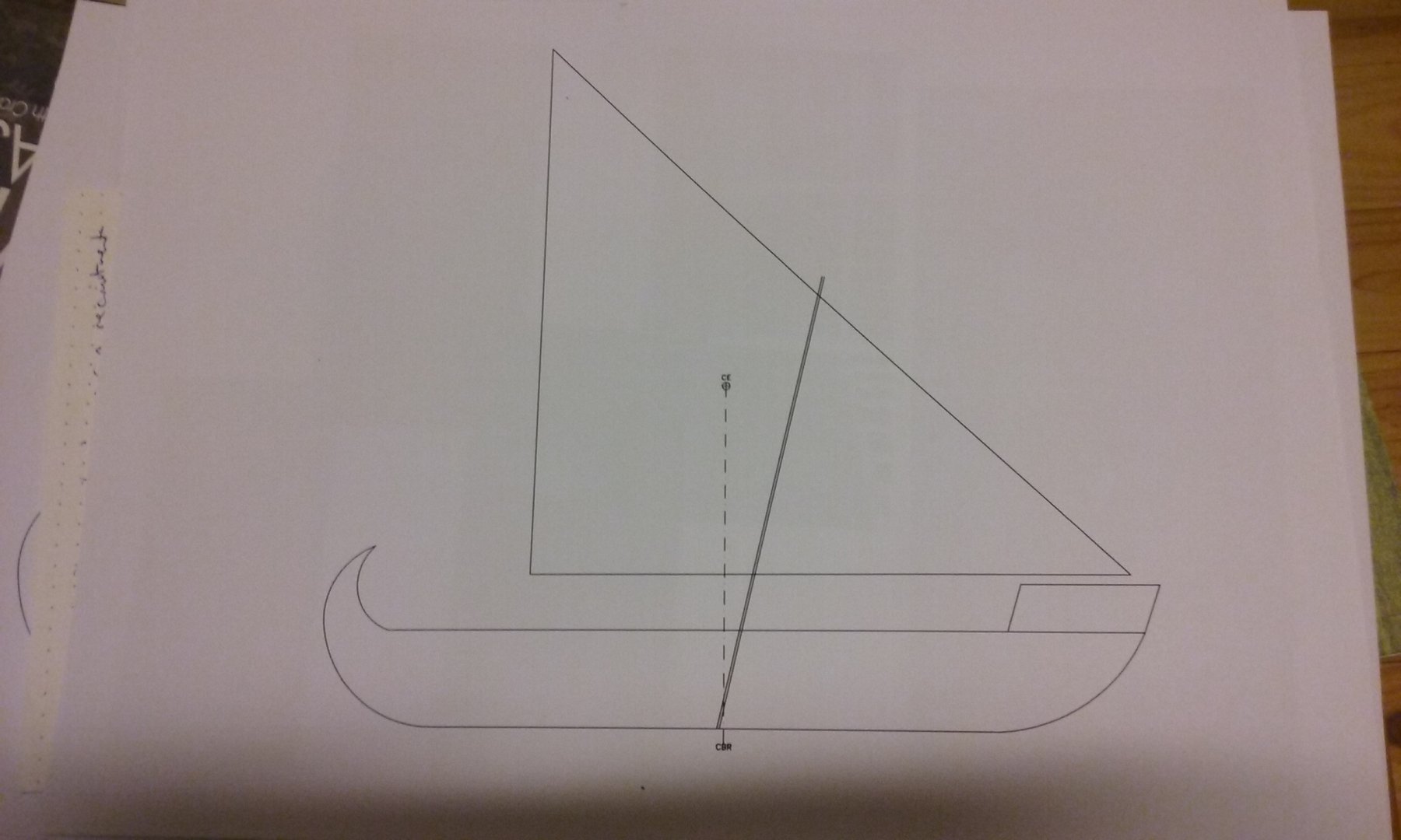
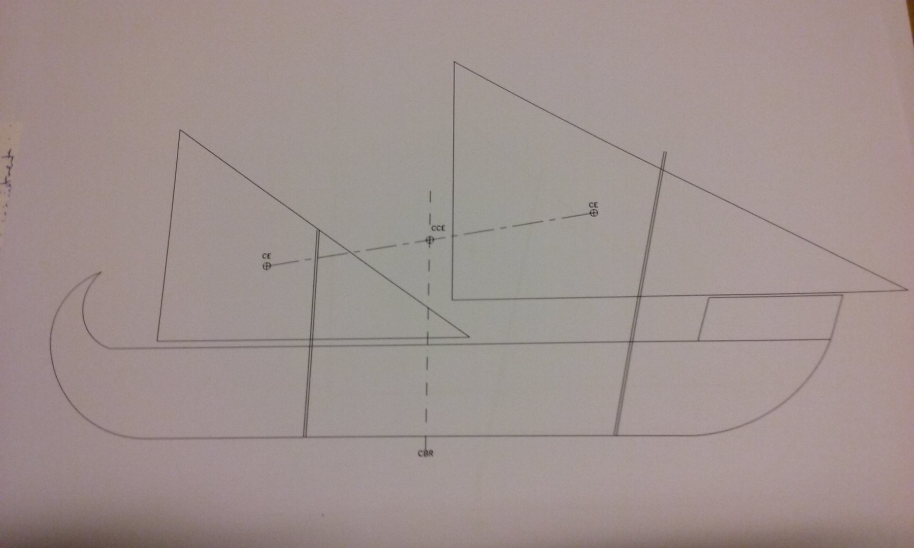
I checked Age of the Dromon again - it does contain estimates of the yard lengths for the two lateen sails - 20.17 and 15.43 metres, based again on 75% of those of the Sicilian galleys. I tried these against the rough drawing of the ship, putting the Centre of Effort directly above the Centre of Lateral Resistance, [edit]while keeping the mast heights the same[/edit]. Note that the shape which produces the most power for a given length of yard is a 90-45-45 degree triangle, but these yards are at 32 and 37 degrees [edit] due to the height of the masts. Higher masts would enable a greater angle. [/edit] However, although modern lateeners certainly sail with the yard at 45 degrees they also quite commonly have the yard at a lower angle, so perhaps this is correct. (Note, by the way, that the above picture shows that the mariners haven't bothered to move the bottom end of the yard to the other side of the mast when they tacked - the sails are being blown against the masts). Certainly you come across a lot of renaissance pictures of lateen-rigged galleys with low angled yards - mostly furled . . . but sometimes also under sail. And the mediaeval pictures also often have yards at a lower angle than 45 degrees (see the posts above). So I'll go with this and see how it works. However, it occurs to me that the Sicilian galleys didn't have a forecastle or central castles as the dromon does, so I'd be justified in having higher masts, which could perhaps have the 90-45-45 triangle after all. I also worked up a drawing of the dromon with a single mast, showing the Centre of Effort directly above the Centre of Lateral Resistance. It looks good too, though the CE is considerably higher than on the two-masted version. [edit] The mast is higher on this one than the lengths shown in the book. [/edit] Steven
_-_WGA25054.thumb.jpg.54449001f9516ac6b737f901ef18b04f.jpg)
-
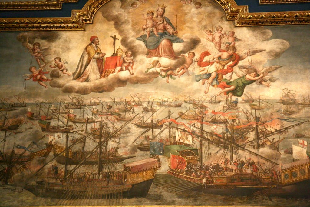
As I have no idea of the mezza lune geometric technique, I can't really comment on the correctness of what you're doing, but it certainly looks good. I notice a very tight curve at bow and stern at what I take to be the level of the second wale. This looked a bit unusual to me, but having had a close look at a fairly large image of the painting your model is based on, it does have that tight curve, which is followed by the brackets supporting the sterncastle. Keep up the good work. As always, very instructive. Steven
- 263 replies
-
- 2
-
-
- nave tonda
- round ship
- (and 2 more)
-
Thanks for all the "likes". Mark, Professor Pryor estimated the foremast would be 11.85 metres long, and the middle mast 8.4 metres - these being 75% of the sizes of the masts of the Sicilian galleys of the 13th century, as the dromon was about 75% of the length of these galleys. I'm currently working on diagrams for the sizes of sails to reach an aggregate of 100 square metres, while having the CE above or slightly forward of the CLR. I chose two configurations adding up to approx 100 square metres - one where the foresail is 12 metres long and the "middle" sail is 8 metres (corresponding to the relative sizes of the masts), and the other where the foresail is 11 metres and the middle sail 9 metres. Doesn't look quite right yet - I think the sails need to be bigger - which in turn raises the height of the CCE. On the other hand, these sails would probably only have been used if the wind was from directly aft, so the ship didn't lean more than the fatal 10 degrees. Still a work in progress. Steven

-
Thanks, LH. That's what I'd thought. Mark, that's an amazing piece of footage. It's hard to believe the ship doesn't get swamped by those seas, but back she comes, every time. An incredible amount of movement (and I'm sure the waves get even bigger at times). Unfortunately, dromons don't appear to have been as stable. Age of the Dromon's calculations are that with over 10 degrees of roll it would swamp the oarports and turn over. VERY little freeboard. Experiments with the trireme reconstruction Olympias seem to confirm the instability. These ships were built for speed, not ocean-going. Steven
-
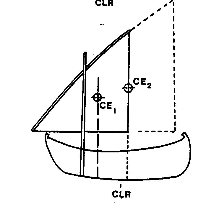
Whew! I've just been studying the theory behind the theoretical sail plan for the Serce Limani ship. Basically, I had the right idea above - the centre of effort (the theoretical point through which all the forces acting on the sail(s) act - has to be directly above or slightly forward of the centre of lateral resistance (the point through which all the water resistance forces act - about amidships). Then we have to estimate what sail area is necessary to propel the ship through the water. This is almost impossible without a lot of higher maths and a lot of computer memory, or a huge tank and a hull model. (I have the model, but I'm certainly not putting it into a tank.) But it can be done by comparison with other vessels. It's been estimated the Serce Limani ship would have needed about 100 square metres of sail. It's short (about 15 metres) and tubby, while the dromon is long and thin (30 metres), which reduces the water resistance per metre, but increases the number of metres of water resistance. So perhaps these two figures cancel each other out (approximately), and I should be allowing for about 100 square metres of sail for the dromon. NEXT, the higher of the centre of effort above the centre of gravity, the more likely the ship is to turn turtle. The bigger a triangular sail, the higher (and further aft) the centre of effort will be. As a dromon will turn turtle if you look at it the wrong way, it seems to me that two masts, each with a smaller triangular sail and thus a lower (and more central) CCE (combined centre of effort) are the better option. Both these diagrams are taken from "The Rig of the Eleventh Century Ship at Serce Liman, Turkey" by Sheila Diane Matthews. My understanding is that it is acceptable to use these for study or discussion, but if the moderators believe it is unacceptable I will remove them. So the masts and sails have to be placed so as to put the centre of effort above or slightly forward of the centre of lateral resistance. I'm going to work this out on AutoCad to get the sizes of sails I need, and where and how big the masts should be, to achieve this. Regarding the larger sail being at the bow, I quote from Age of the Dromon: "from antiquity to the end of the Middle Ages all lateen-rigged ships of all kinds, including war galleys, always had their largest mast and sail towards the bow and a smaller one towards the stern. The documentary evidence for this for Western galleys of the High Middle Ages is very clear and there is no reason to suspect that it was not the case also for similarly-rigged Byzantine dromons". Which pretty much puts it in a nutshell. I'll go with this and see where it leads. Sigh. Steven
-
Very interesting, Dick. Some nice research, which seems to be reaching a good result. Steven
- 263 replies
-
- 4
-
-
- nave tonda
- round ship
- (and 2 more)
-
Mark and LH, As I understand it, it's important to have the larger lateen sail towards the bow, otherwise the ship can't be properly controlled - the "centre of effort" has to be forward of the "centre of resistance" (which is effectively amidships), so the ship is being pulled through the water instead of being pushed through it. Certainly, that's my understanding, and Age of the Dromon states this was the invariable practice with mediaeval lateeners. With our own square-rigged tradition, we tend to expect the middle mast to be the biggest, but the lateen rig works differently. I'm doing some more checking on this - there's a very good thesis on the rig of the Serce Limani wreck which goes through the theory in some detail, and I'm going to go through it again, but I'm pretty sure that having the bigger sail towards the bow is correct. Making the middle mast thicker and longer may solve some of the issues, but I'm also not totally confident of the mast lengths - how much similarity was there really between the rig of an 11th century Byzantine dromon and that of a 13th century Sicilian galley? Two hundred years different and a different society and culture, with Western rather than Eastern shipbuilding traditions. However, my major issue is really the conflicting information about whether these things had one or two masts. I'll give it a go with a new middle mast, but I'm keeping my options very much open. Steven
-
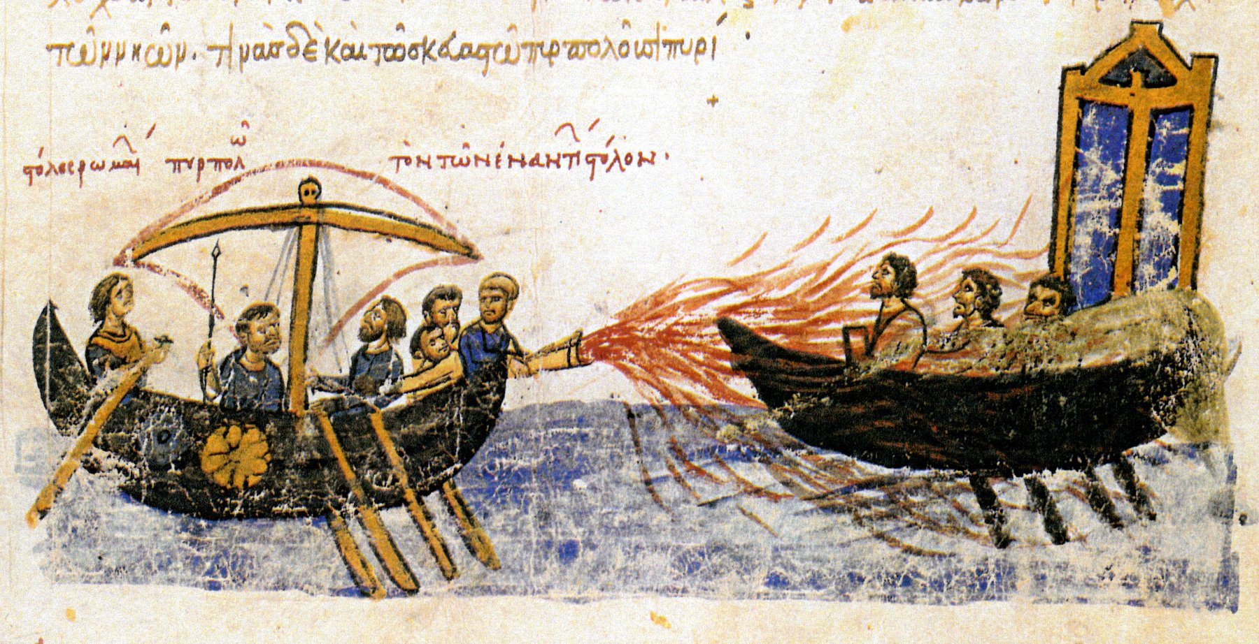
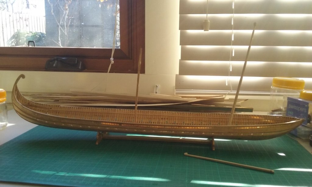
Well, I finally got the mast steps and masts together and dryfitted into the hull. And really, not very happy with the result. I based the mast lengths and positions on those in Age of the Dromon, (calculated by extrapolation from the known mast sizes of Sicilian galleys of the 13th century) but they just look wrong. I checked and discovered that I'd made the middle mast too short; fair enough, my mistake. But even when I put in a dummy mast the right length, it still didn't look like the two masted lateeners in contemporary pictures, even allowing for artistic licence and the tendency of artists of the time to make the ships smaller, shorter and tubbier than they were. I'm having serious doubts about the whole issue of two different kinds of masts (which comes from Age of the Dromon) and all through the build I've had a problem with the idea of two masts rather than one. The evidence on which the two-masted concept is based is equivocal - some points to a single mast better than it does to one (for example for the Crete expedition of 949 AD twenty dromons were to be provided with twenty masts. Sounds like one mast per ship to me. But the explanation for this in the book is that these masts (described as khalkisia) were "blockmasts" - with sheaves at the masthead, and that there would have been another mast without sheaves - the one with the hockey stick top. But then the two masts would have been of different types, which doesn't tie in with the pictorial evidence. I'm prepared to give it another go - make another middle mast, and make it the same thickness as the foremast, and see how that looks. But I may end up going with a single mast after all, as shown on the only picture I know to be of a dromon of the right time (it has two banks of oars and shields on the sides, and is using Greek Fire.) Steven


-
Exactly, Mark. Those were the considerations I had in mind when trying to come up with a design for this. I expect the mast would also have been wedged in place as it passed through the deck. Funnily enough, the "strong" part doesn't seem to have bothered the Byzantines all that much - some mast steps were just fixed to the floor of the vessel with a couple of nails, some were loose - just held in place by the weight of the mast! Thanks, Banyan. Much appreciated - particularly from the builder of the HMCSS Victoria, which I've been following with great admiration. Thanks everyone for the "likes". Steven
-
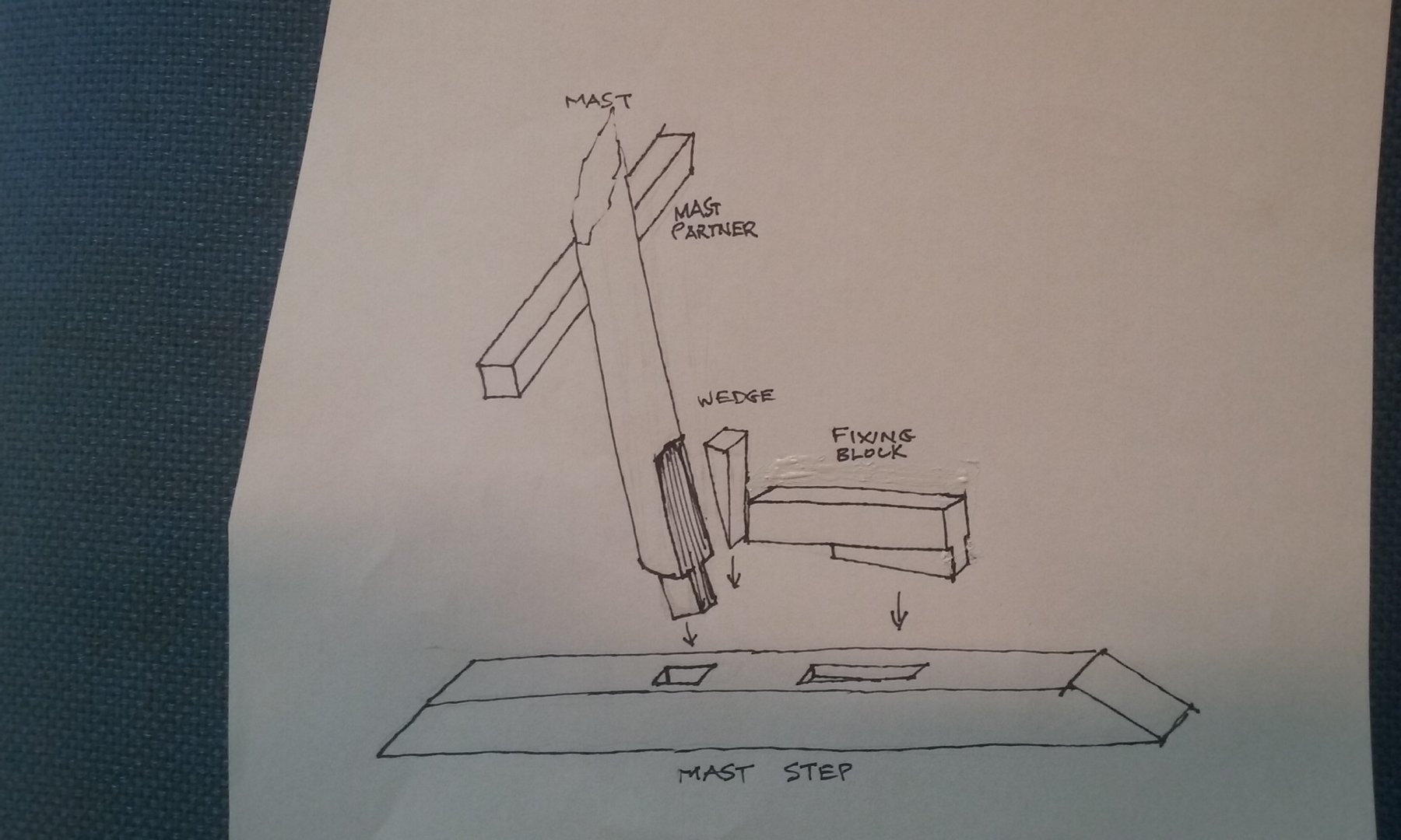
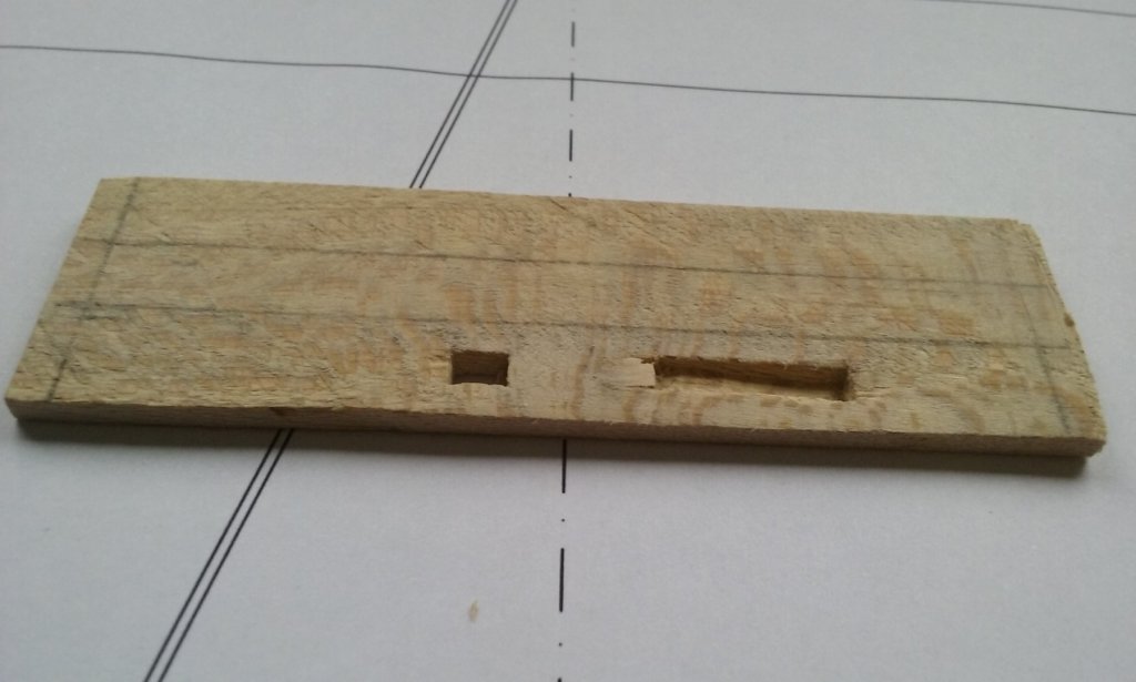
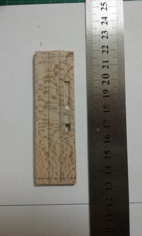
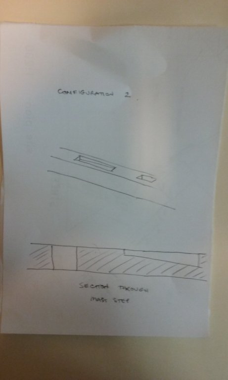
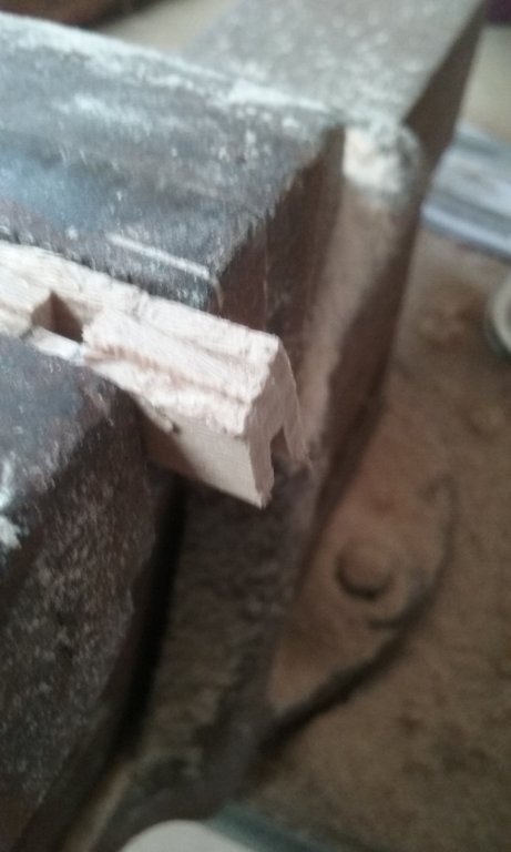
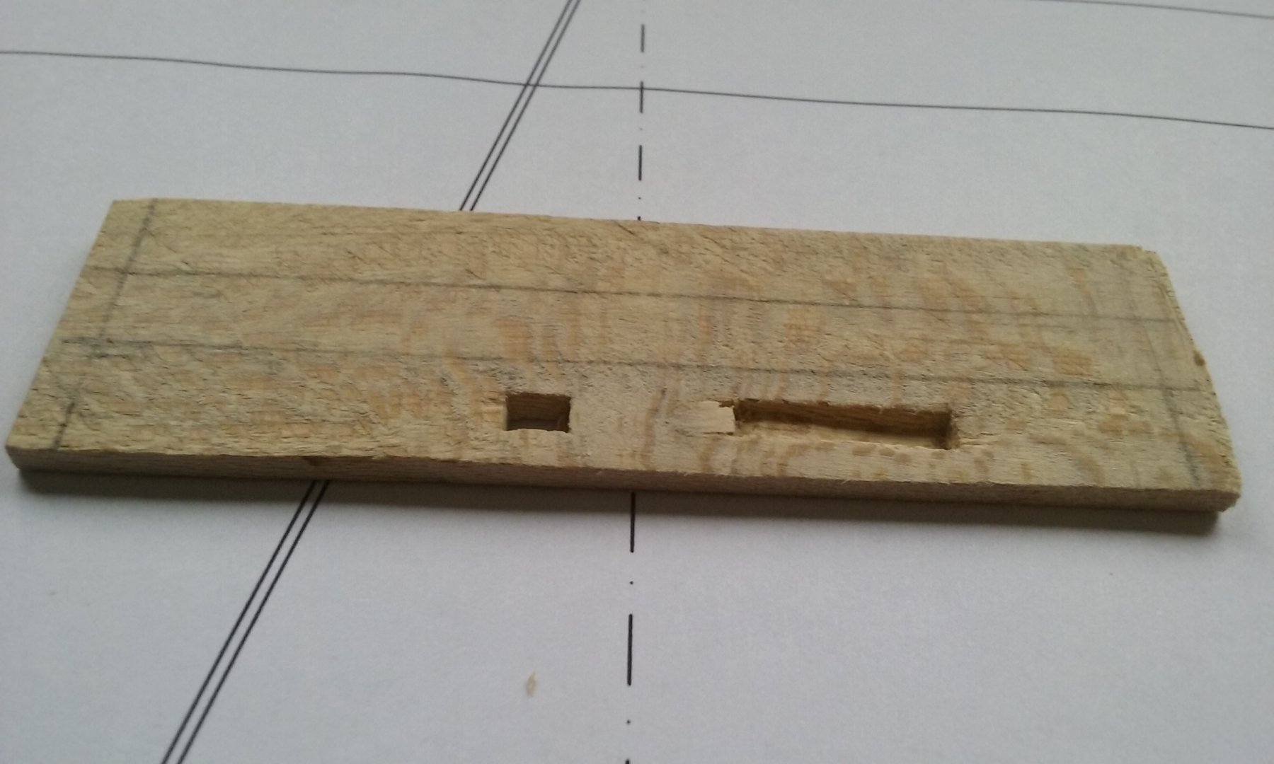
Here's my idea of how the mast step in Byzantine vessels worked. I haven't tried it out and don't know if it would really work, and I certainly don't know if that's what they actually did, but it's a possibility. The mast sits in the forrard mortise with the fixing block slotting into the other mortise, and a wedge between the two to secure the mast and also impose a rake on it as it leans against the mast partner. The angled bottom of the second mortise would enable the fixing block to be dropped into place and help it stay in place against the horizontal force from the mast and wedge. That's my idea, for what it's worth. Steven

-
No, those look like square sails (seen side on) on both fore and main masts (with a furled topsail on the main), which would make it a brig. I'd expect there to be a gaff sail on the main, but I can't see one (or even the spars) on the drawing. Unless the sail isn't set and that somewhat curved angled line near the top of the main course is the gaff, and the sail is loose footed, so doesn't have a boom? Steven
-
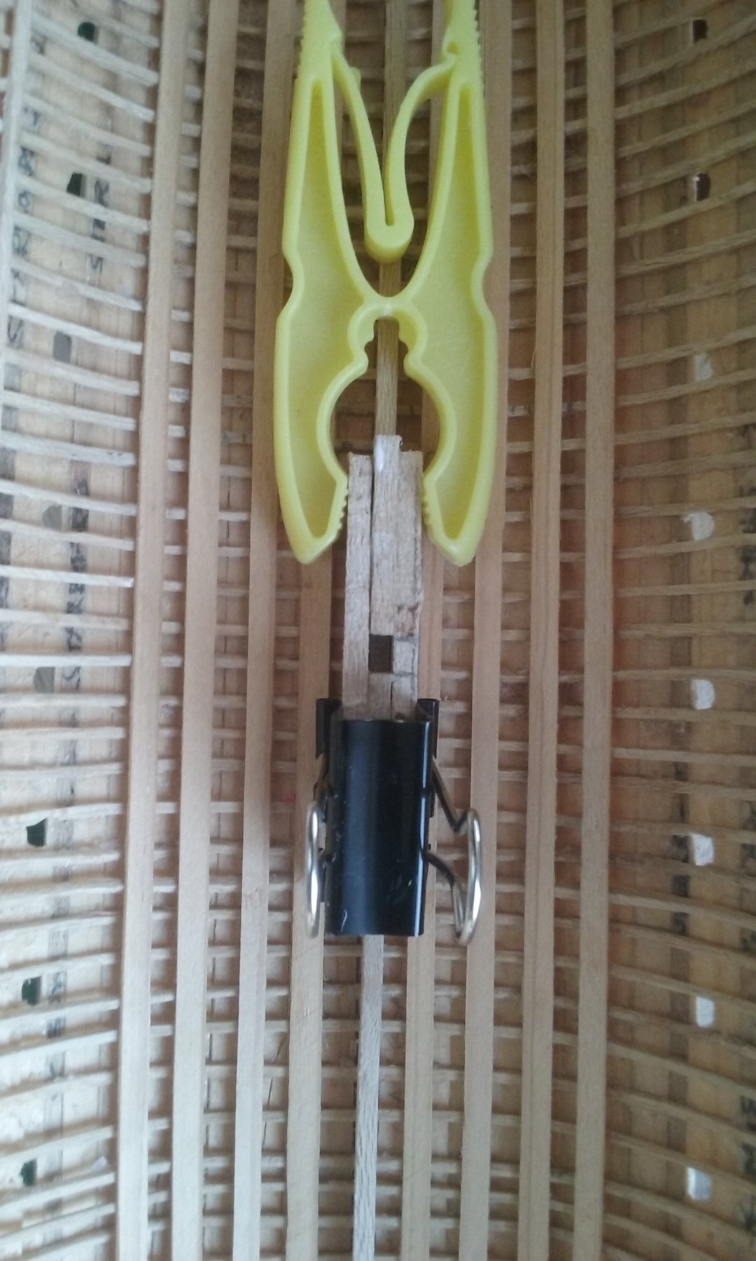
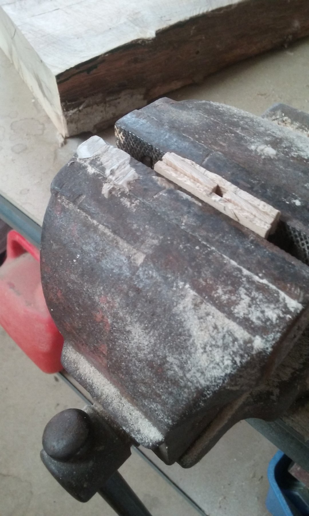
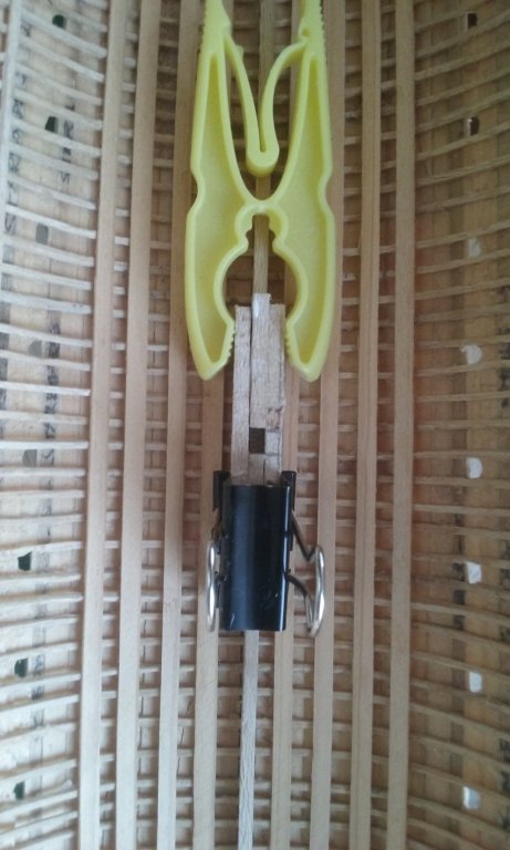
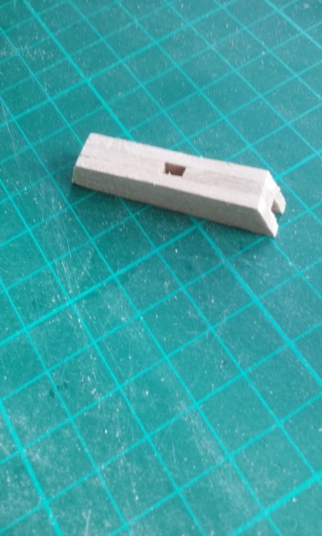
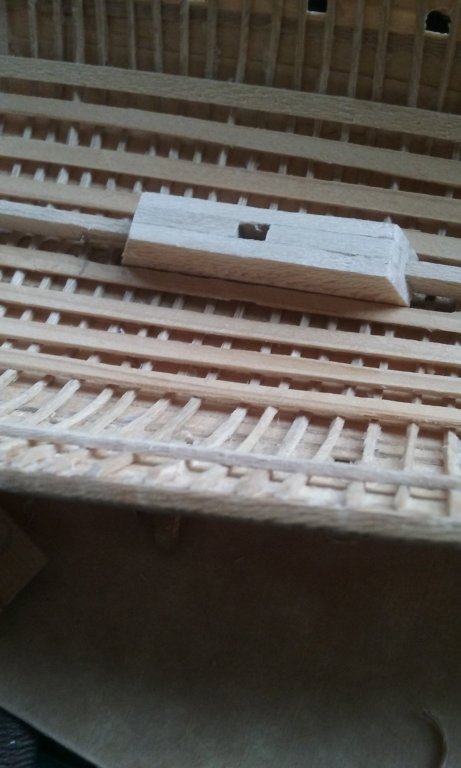
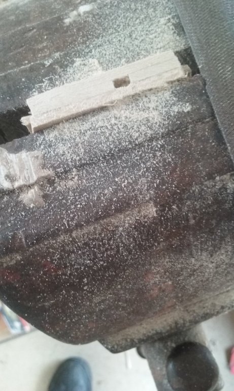
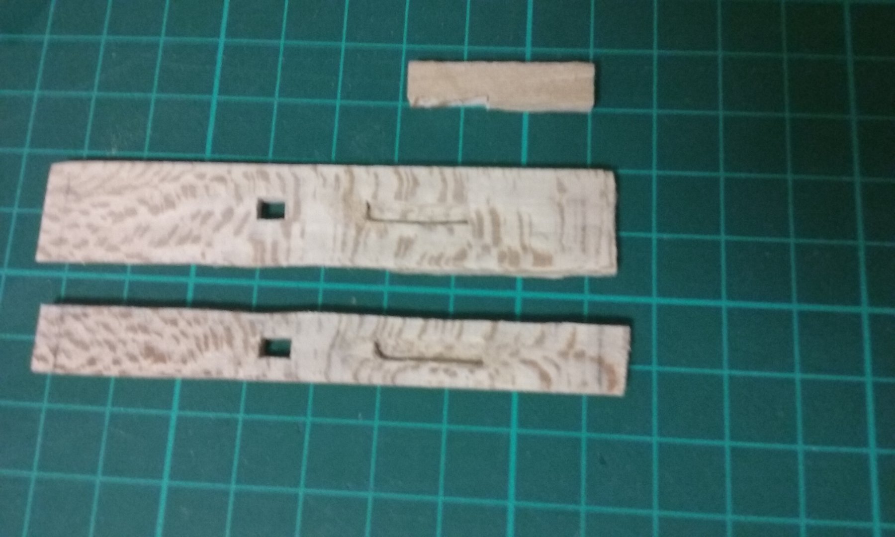
Onto the mast steps. I've been very fortunate that Professor Cemal Pulak of the Texas A&M University who took part in the excavation and study of several of the Yenikapi wrecks in Istanbul has kindly provided me with information and advice on various aspects of the wrecks, including the mast steps. I'm very grateful for his help. The Byzantine mast steps are a bit of a puzzle - there are aspects of them that haven't yet been satisfactorily explained. The ones that have been found have each had two mortises - one a simple slot, the other longer and with an angled base to the slot. The simple slot is (in one wreck - they vary from ship to ship) about 200mm (10") long and about 600mm (2 ft) forrard of the other which is about 800mm (2'7") long. The angled base is deeper aft than at the forrard end. By the way, despite my drawing, in most mast steps found the straight mortise doesn't go right through the step - it stops short. Exactly how this worked is still unknown, though there are currently a few theories. I've got my own ideas which may or may not be correct. None of the wrecks discovered has been found with both mast step and mast partner in place, so the relationship between the step and the mast is not known - which is why it's difficult to figure out how it all worked. For my own model, unfortunately I introduced a further complication when building the hull. I was under the impression that all the wrecks had keelsons, so I put one in my model. Now it turns out that very few had them. The wreck I based mine on was one of them and its mast step hadn't survived, so I don't know what kind of step goes with a keelson. So I've done something which could have worked but hasn't any firm basis in archaeology. It doesn't have the two mortises (I didn't have long enough pieces of wood the right thickness), but it should do the job. I'd have preferred to do it exactly right and test out my theory about the two mortises, but it's probably too small a scale to test it out properly anyway. And as it's all going to be hidden below decks it doesn't really matter too much. Here it is: Glueing one side piece to the centre pieces to make the mortise. I could have used a single piece and cut the mortise out but this seemed easier. Adding the other side piece Cutting the angled ends of the assembly. smoothing off the top with a file: Finishing off, and the assembly dry fitted in the hull. The eagle-eyed among you may notice that the pictures don't quite align with each other. That's because I fudged it a bit. I've taken photos of the various stages of the two different mast steps and combined them as though it's just one. Steven


_-_WGA25054.jpg.b31a19998923a51ee8ee023a35a32e86.jpg)