HOLIDAY DONATION DRIVE - SUPPORT MSW - DO YOUR PART TO KEEP THIS GREAT FORUM GOING! (89 donations so far out of 49,000 members - C'mon guys!)
×


Louie da fly
-
Posts
7,989 -
Joined
-
Last visited
Content Type
Profiles
Forums
Gallery
Events
Everything posted by Louie da fly
-
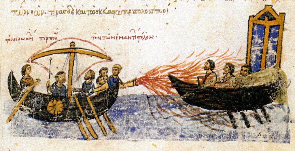
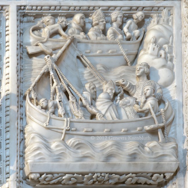
 Mark, I'm by no means an expert in the lateen rig, but the three lines running from the masthead to the side of the ship are the shrouds, which give the mast sideways support (there's another three on the other side of the ship). In Mediterranean vessels of this period the shrouds were adjusted with pairs of blocks (tackles) rather than the deadeyes that were used in northern Europe and were later adopted in the Mediterranean. The rope at the lower end of the yard is the tack, which holds this end of the yard in the correct place to take best advantage of the wind. I The rope near the top end of the yard has been variously described as a brace or a vang - it was to manoeuvre this end of the yard. I believe it was fairly common to have one each side of the yard. There is also the halyard - a rope to haul the yard up the mast (via a sheave or pulley in the mast) and hold it in its proper place. You can see both sides of it - one going up from deck level (partly hidden by the guy bending over in the bow who seems to be working on the anchor cable) and the other returning downward (running parallel with the mast itself and partly obscured by the guy standing in front of the mast who is holding onto a shroud). Or maybe the other way around. The end you haul down on is called the downhaul. I can't remember the name of the other end. There are two other lines showing in this bas-relief; the anchor cable and a line to help control the side rudder. They're not doing anything to the mast - the ship is simply under sail with the usual lines you'd expect to see on a lateener. They might be adjusting the height of the yard with the halyard, but I don't think so. There isn't all that much info around on the rigging of a lateener - I once had access to a site which was very helpful, but I lost it along the way and can't find it again, much to my disappointment. If anybody spots any mistakes in the above, please don't hesitate to correct me. Hope this helps, Steven PS: There are some very nice pics and videos of lateeners under sail at http://forum.woodenboat.com/showthread.php?156203-Lateen PPS: Just looked at your profile, Mark. Didn't realise you do a good bit of sailing, and a lot of the stuff above would be teaching grandma to suck eggs.
 -
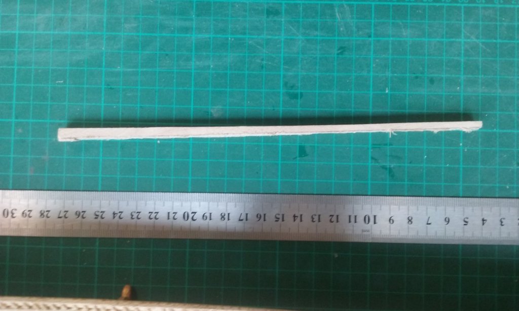
Thanks for the likes. Cog, the same thing occurred to me - that a separate unit might be a source of weakness. The third picture seems to indicate it as separate, but it could certainly be interpreted that the mast had been made thicker to take the forces acting through the sheave . I'm still in two minds about it. Steven
-
On further pondering, I have come to the conclusion that the "blob" in the first picture is an oversimplified version of the one in the third picture - that is a unit containing a single sheave through which the halyard runs, but that the artist in each case shows the openings on both sides of the sheave in one view (not unlike Picasso.) That's my interpretation, anyway and that's what I intend to go with. I may make the unit containing the sheave a separate piece attached to the top of the mast. I haven't decided yet, but it certainly looks like that is what it is. Steven
-
I'm now working on the form of the fore (main) mast. The 12th century copy of the Chronicle of John Skylitzes held in the Biblioteca Nacional in Madrid contains three pictures of galleys under sail, each of which has a construction at the top of the mast which appears to contain a pair of sheaves, through which I believe the halyards pass. This can perhaps be seen more clearly in the 12th century bas-relief in the church of San Pietro in Ciel d'Oro in Pavia (this photo appears in Genevra Kornbluth's site at https://www.kornbluthphoto.com/Ships.html ). Though the thickness of the ropes seems exaggerated, the curious attachment of the shrouds to the masthead appears in several other representations - in the shrine of St Peter the Martyr in the church of Sant' Eustorgio in Milan, and also in a picture of a galley in the 15th century treatise of Michael of Rhodes (see my posts of July 6 and July 8 2015). The "blob" at the masthead isn't present in this bas-relief, but it is in another representation from about 1310-1320AD which is from the Byzantine church of St Nicholas Orphanos in Thessaloniki, of the Saint saving a ship in a storm. This has more detail and I will probably be following this picture fairly closely. After the false start of the previous post, I've begun on a new mast incorporating the "blob", which I hope will work better. Sorry about the photo quality - it's from my phone. I'm a total newcomer to all this stuff - I really don't know how the lateen rig works except theoretically and I'm feeling my way, hoping I haven't got it too wrong. I'm also still researching the mast step, of which more later. Steven
-
That lathe is brilliant, Tom! I've been agonising over the cost of modellers' lathes and I think your solution is just what I need myself. Steven PS: Great news over getting new employment with a relatively short gap in between. PPS: The cannon barrels look very good. They're about an inch and a half long, right?
-
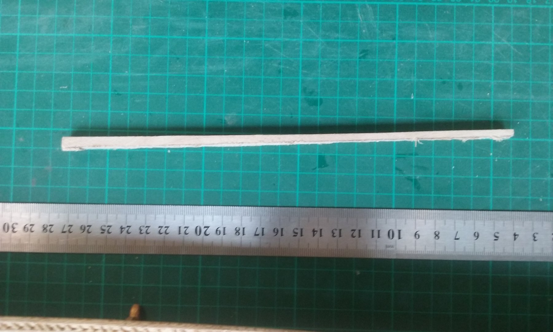
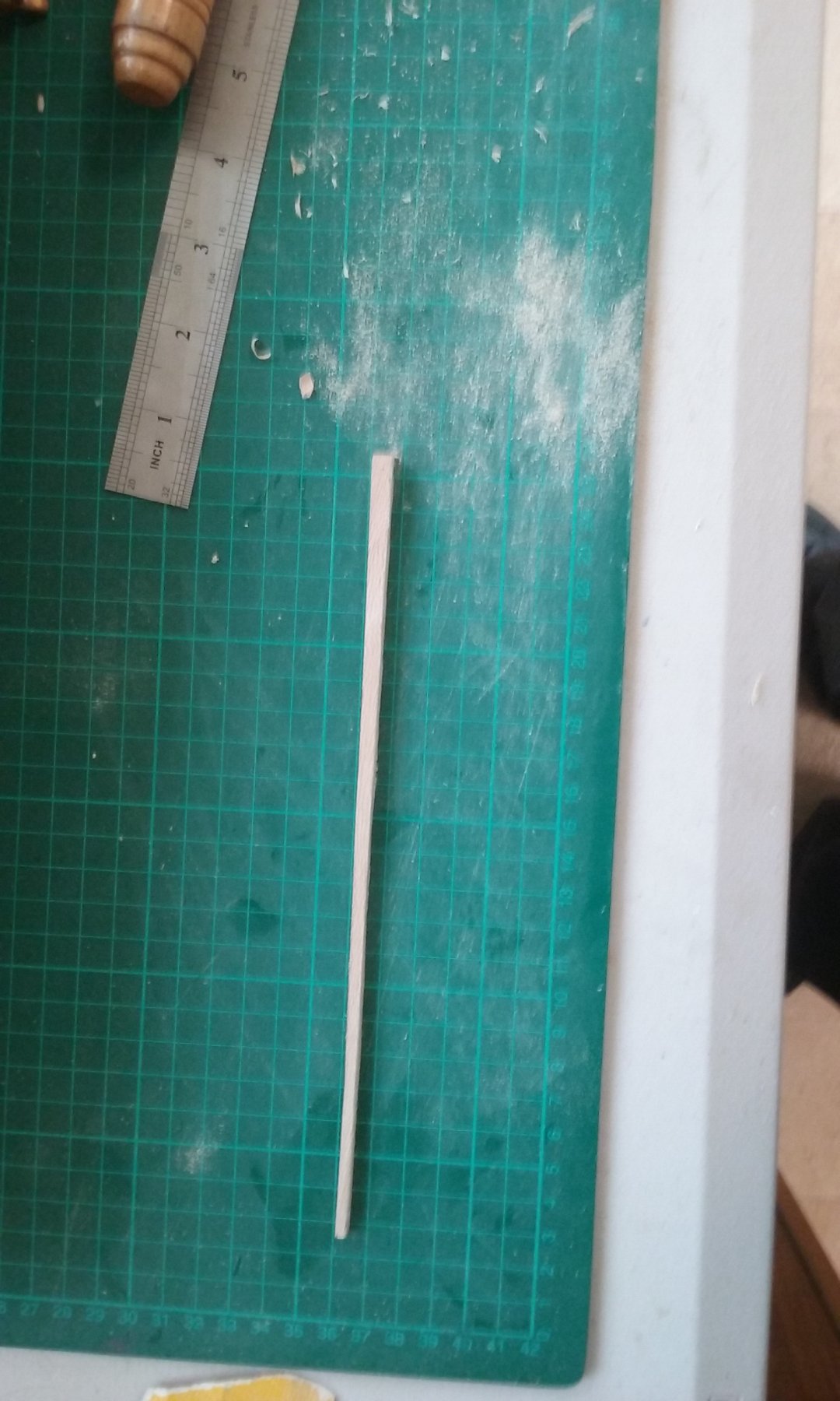
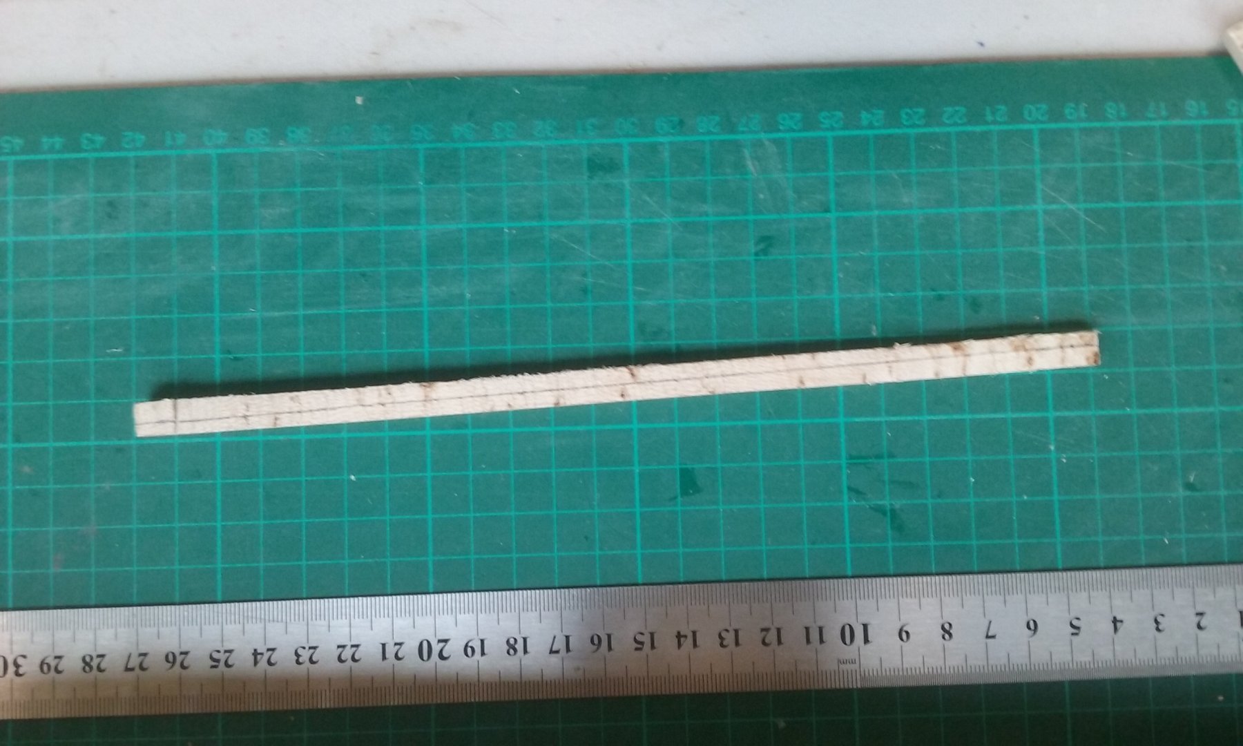
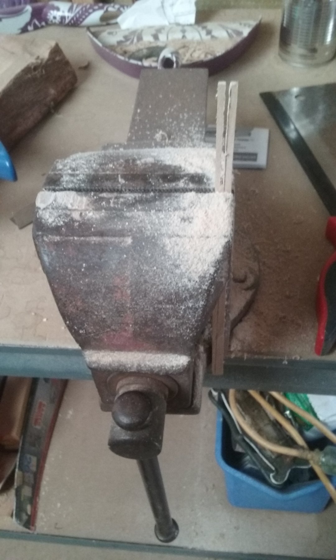
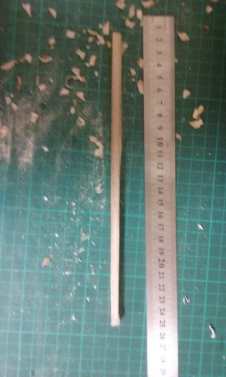
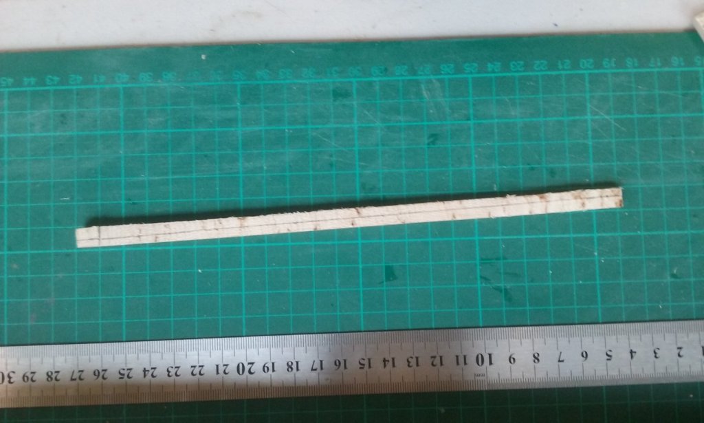
Well, a lesson in what they call "due diligence". I used some wood previously sawn by the guy across the road (I don't have a bench saw) to start making the foremast. I marked it out, put it in a vice and cut it tapered in both width and thickness with a tenon saw (best tool available, I'm afraid), leaving a bit extra for "wriggle room". As you can see below, the wood broke off on the final cut because the sawblade reached the edge of the wood. But I was expecting that and wasn't worried. Trimmed it down with a Stanley knife (I don't have a plane) and then used a file to get both cut edges nice and straight. The plan was to then convert it from a square section to an octagonal section, and thence to a circle, which is what I'd done with the oars. But I'd wrongly assumed the original sawn edges (from the bench saw) were straight. BIG mistake! When I had it all nicely squared off, I discovered those edges were bowed inwards and the mast was too thin at the narrow end. Nothing I can do - I just have to bin it and make a new one. Had I checked it for straightness at the beginning, I could have allowed for the crookedness and got it right. Back to the sawbench . . . On the other hand, during this process I've been researching contemporary representations of the type of mast I want to make, and I think I was on the wrong track anyway. So maybe it was just as well. The new, improved model should be closer to the original. Steven


-
Piet, I came across this site http://dioramas-and-models.com/how to do it.html which has the best explosions I've ever seen in modelling. It uses cotton, LED lights and (sometimes) cellophane, and looks very good in photographs. I don't know whether it's as good when you see it "live", but it might be worth considering.
- 378 replies
-
- 4
-

-
- java
- pacific crossroads
- (and 2 more)
-
Patrick and John, thanks for the comments. It's funny, I'm always gobsmacked by the patience and workmanship of other people (including you two guys) - I'm too well aware of my own goofs. Probably a good thing. It gives one the humility to always strive to do better. Steven
-
You know, I'd really never noticed that. But it's true - most 16th century galleons had the foremast in front of the forecastle, not in it. Amazing the things that you just don't see. Excellent work as usual, Patrick. Steven
- 756 replies
-
- 3
-
-
- galleon
- golden hind
- (and 2 more)
-
John, You've done a wonderful job on this. I wish I'd thought of this earlier - I did a bit of a browse on "Maori war canoes" and came up with a couple of contemporary (European) eyewitness pictures showing the problematical sail in somewhat more detail. Sorry it's a bit late, but it might be of use when it comes to the Polynesian canoe. There's one from 1770 at https://commons.wikimedia.org/wiki/File:Maori_war_canoe,_drawing_by_Alexander_Sporing.jpg and another from about the same year at https://www.sciencelearn.org.nz/resources/632-waka-revival , though I think the second one is from Polynesia rather than New Zealand. There is also an article at https://stampaday.wordpress.com/2018/02/19/outrigger-canoes-of-fiji/ which though it's ostensibly about Fijian canoes, has quite a bit of information on the New Zealand ones and even has an early twentieth century photo of two Maori canoes under sail, (which perhaps are using the traditional fabric for their sails). Hope this is of interest (and not just annoying because too late), Steven
-
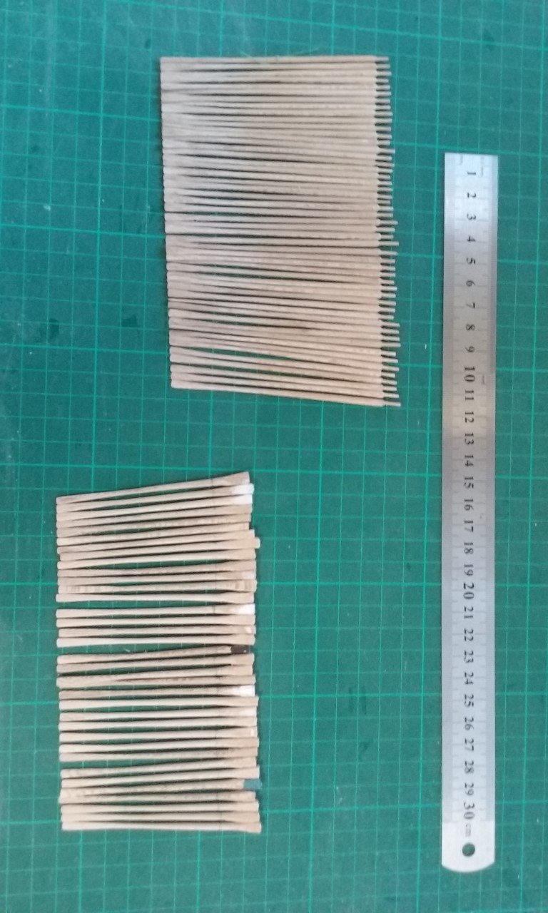
A real milestone - I've just completed the 100th oar, so all the oars are DONE! (And for any purists who may insist I should have spares because they had them in the original . . . nah.) Before I put everything together I have to trim the bases of the lower bank of oars (the bundle on the right) so they're all at the same level and angle when in place. I've temporarily put the frame to support them in place in the hull. I still have some work to do before I'm ready to glue it in position. This is all going to be a bit fiddly, but I'm pretty sure I've worked out a sufficiently cunning plan to dry fit the oars and then take them out and only glue them in position later, so in the meantime I can work on the rest of the ship without the oars getting in the way and perhaps getting broken etc. But before I do that I have to put in the mast steps - which I'm still looking at. It seems to me from the archaeological evidence that the slot in the mast step is rather longer than the tenon of the mast that it is to contain - which probably means wedges in the slot, fore and aft of the mast itself. When I get to deck planking I think I'll have to part-complete it and add the oars and masts while I can still see enough below decks to put them in place. The deck beams are going to be a challenge in themselves. So many of the damned things, probably as thin as the frames. Still considering how I'm going to make them. And after the oars are sorted out, I can put in the companionway down to the lower deck, finish planking the main deck, then put in the crossbeams and support structure for the rudders, and then the prymne (poop deck). And then the forecastle and centre castles . Oh, and . . . It seems you always have to be thinking at least a dozen steps ahead in this game . . . Steven
-
Nice dolphins, Dick. And the perspex makes it seem they're the only thing holding the ship up. Steven
-
Nice job, Steve. The characters look very convincing and appropriate. Steven
-
Me too! There are still quite a few around on the Murray - in Mildura, Albury and Echuca that I know of, and perhaps more. Steven
- 599 replies
-
- 4
-
-
- sidewheeler
- arabia
- (and 4 more)
-
That's even better. It looked to me like they were to one side, but on closer inspection I can see they are indeed on top. That's pretty much what I'd decided to do for my own model, so it fits very well with what I had planned. The knees would probably be needed to overcome any sideways "rolling" torque on the step, which would otherwise have been perched rather precariously on top of the keelson. By the way, I've now been informed that the last photo I put up is not from a galley, but from a 6th century merchantman (YK35) - not really appropriate to my time and ship type. What I'd thought was a mast step is indeed just that, but surprisingly it wasn't fixed to the hull in any way - it was just kept in place by the weight of the mast. Seems rather bizarre to me . . . Steven
-
That's fantastic, Dick! Just what I needed. (And about the same length as the mast steps I'd already made, though a little different in form). I note that the steps are actually next to the keel, just to one side. That makes a lot of sense structurally - no compromising the strength of the keel caused by cutting into it. Plus knees either side of the step to make everything firmer. I know this isn't from exactly the right time and place, but I should think the technique would have been very similar, though the details may have varied. Thanks very much for this. It's a great help. Steven
-
Mark, Another way to lift the mast clear of the deck would be with sheers, as on a sheer hulk. This technology was definitely available at the time, as well as blocks, so should be relatively easy, even at sea - so long as there wasn't too much of a swell. (But they would only have lowered the mast on going into battle, which they wouldn't have done in rough weather - the ships were far too unstable for that). As the ship had a crew of over a hundred, no shortage of labour! The masts were lowered onto a "stand", presumably above head height, running fore and aft. As lateeners don't have stays, perhaps a shroud could be led forward to enable the mast to be lowered aftward under control. I should explain an earlier comment about the ships found with mast steps not having keelsons. The thing is that all the galleys I've come across seem to have had keelsons, but no evidence of a mast step. So how does one attach a mast step to a ship that has a keelson? The last photo above suggests either a rather thick keel that doubles as a step, or perhaps a sort of "box" built around the keel to take the step. Druxey, I certainly live in hope that the Black Sea wrecks will provide some information - but at the stage I'm at it will probably be too late for me to incorporate it into my build. Woodrat, sorry for not acknowledging your contribution about the Contarina wreck. I must have scrolled past it without noticing it - today's the first time I've seen it. Thanks for the information. Are there any detailed pictures of the steps? (probably not, or you'd have sent them, I expect). At a bit of a stall at the moment - been very busy with work and family and haven't been able to do anything on the ship for at least a week. Hoping things will change and I'll be able to get back to it. Steven
-
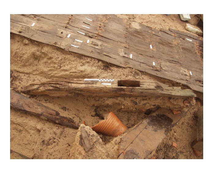
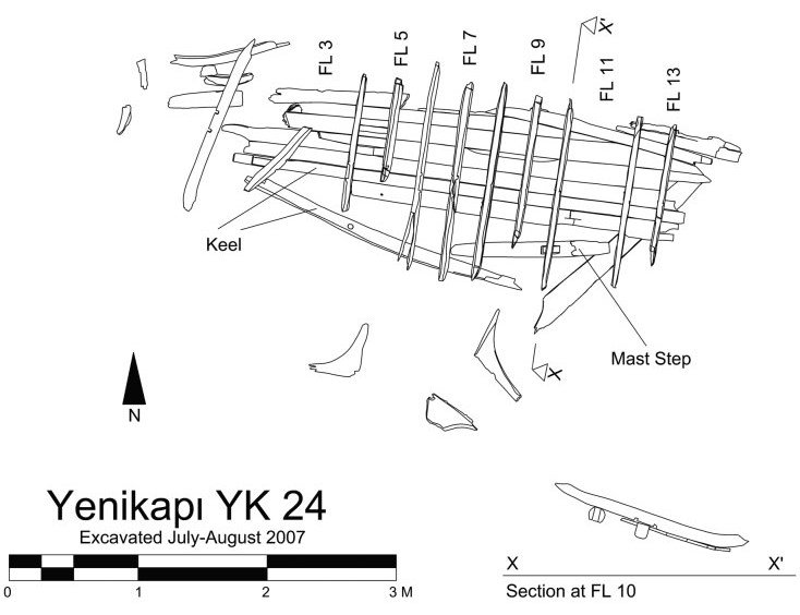
Good points, Mark. I don't think these masts were all that huge, in fact. When I was first researching this model I worked out how much a mast would weigh and decided it could probably be handled by a relatively small number of people. I'll have to chase up and find my calculations again. As the dromon was fully decked, the mast step would only have to support the mast and keep the base from moving too much - wedges at deck level would hold it firmly and at the correct angle. Then the mast could be lifted a little to get it out of the slot then rotated around the hole in the deck to lower it. Should cover several of the problems you mention above. All sounding pretty good, in fact. I should have given credit for the photos in the above post; - those of YK12 were from the paper The Latest Link in the Long Tradition of Maritime Archaeology in Turkey: The Yenikapı Shipwrecks by UFUK KOCABAŞ of Istanbul University, Turkey, which appeared in the European Journal of Archaeology 15 (1) 2012. -the photos of YK24 are from Eight Byzantine Shipwrecks from the Theodosian Harbour Excavations at Yenikapı in Istanbul, Turkey: an introduction, by Cemal Pulak, Rebecca Ingram and Michael Jones of the Institute of Nautical Archaeology at Texas A&M University, which appeared in the International Journal of Nautical Archaeology (2015) 44.1: 39–73 By the way, I have a contact who may be able to tell me which ship is depicted in that final photo and whether or not it's a galley and has a mast step. If so, it would be a great help. Steven
-
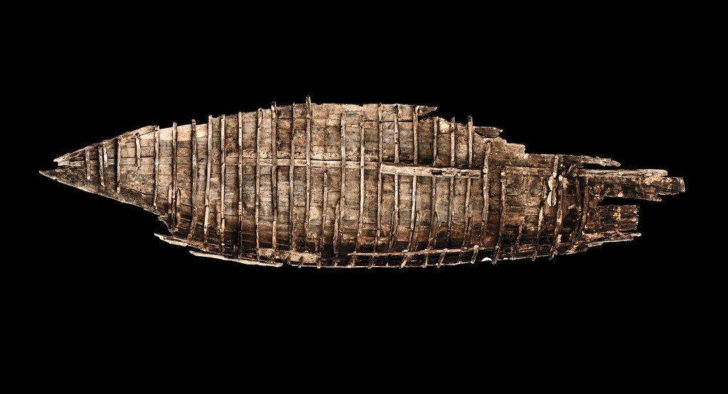
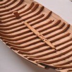
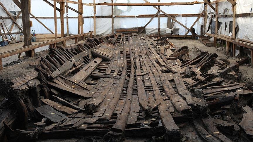
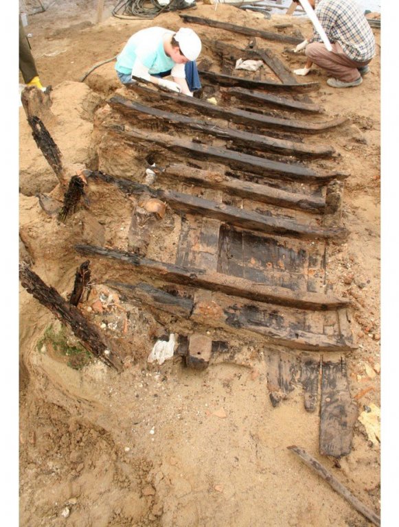
Thanks everyone for the 'likes'. Mark, I really hadn't given it much thought until your question. As it was all going to be below decks, it wouldn't be visible anyway, and I thought I'd just do something that would support the masts and be satisfied with that. But once you brought it up I started looking at the archaeological reports of the Yenikapi dig and found photos of at least two, possibly three mast steps. The first is from the wreck designated YK12, a small (9 metres long) merchant ship. Here is a photo of the ship as found plus a reconstruction, in both of which the mast step is clearly visible. YK24 had a mast step which had been nailed to two of the frames but had come adrift. Another was found with a mast step (designated YK6), but no pictures were available. And yet another ship had mortises cut in two of the frames, thought to have been to fasten a mast step in place. As you can see, both of the structures acknowledged to be mast steps have a simple rectangular slot to take the mast, and there seems to be no evidence of it being angled. This does help explain a contemporary Byzantine treatise on dromons describing masts becoming unstepped in strong wind, which I'd regarded as a somewhat unlikely if they were properly fitted. If it was no more than a simple slot, it would be rather vulnerable to losing its mast in adverse conditions. However, neither of these ships has a keelson - the mast step is just fastened to the transverse frames. None of the known galleys (all of which have keelsons) have any evidence of mast steps, though they are almost certain to have each had at least one mast. But there is another photo of a ship with a feature which might be a mast step (at the left of the photo) - I don't know the ship's designation, but it is from the Yenikapi excavations, and judging from the number of longitudinal stringers (used to prevent hogging in such a long narrow vessel) it may be a galley. If this photo does depict a galley and if the slotted structure is a mast step, then perhaps I have a model to work from. But that's a fair bit of speculation, and I don't have as much confidence in it as I'd like if I'm to use it as the sole basis for my own reconstruction. However, the rectangular slot is a pretty definite, and I will be using that. Steven
-
Hmm, interesting. I'll have a look at the guide blocks as a possibility; it sounds like a better method than my own. Thanks for the suggestion. No mill available, so I'll have to give that one the go-by. Steven
-
John, it's been a while since I checked out your log and I've obviously missed a lot of the progress you've made. I'm very impressed by the amount of painstaking research you've done and the care and attention to detail in your work. A very unusual and worthwhile model, and I look forward to further developments. Steven
-
Thanks everybody for all the likes. Banyan, I haven't worked that out yet. What I had in mind was to mark the rake on the side of the mast step, and using that as a guide, mark the entry and exit points of the holes and then drill a very small diameter hole trying to join them as closely as possible, then carefully enlarge the hole to correct any misalignment. Hope it works! Steven
-
Those waves are looking very good, Tecko. I think I'll steal your idea when I come to make a diorama (imitation is the sincerest form of flattery ) Steven
-
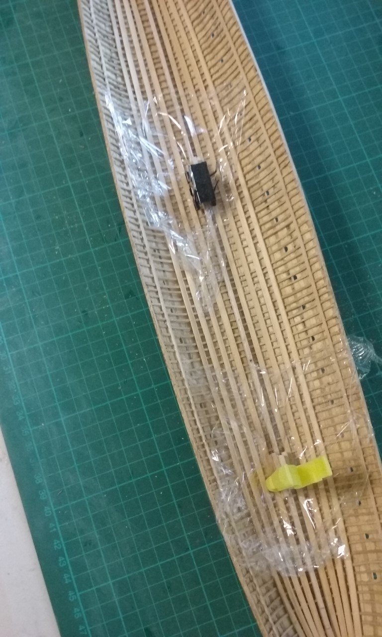
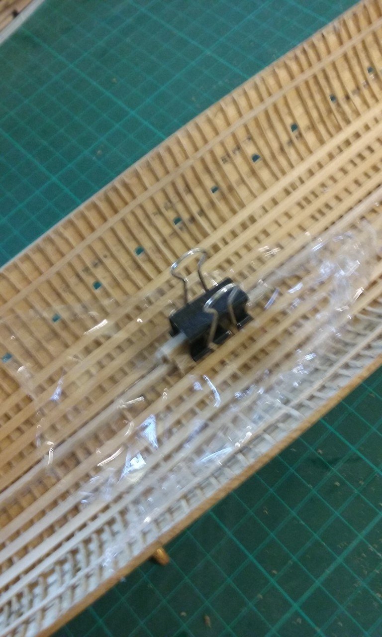
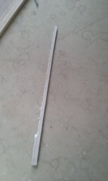
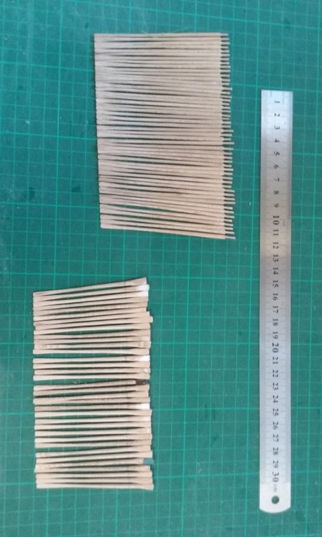
The blades for all 50 upper bank oars have been re-shaped , and 35 of the 50 oars for the lower bank are made. Only 15 to go. Upper bank at the top of the photo, lower bank below. Photo quality's not fantastic, I'm afraid. I've also started work on the mast steps for the two masts. Each is made using three strips of wood glued together to create a readymade slot for them to fit over the keelson. I've used clingwrap to keep them from sticking to the keelson. Once the glue is dry, I'll shape each mast step properly and then put a hole through each at the appropriate angle for the mast rake. Still have to make the masts - I should probably do that before I make the holes to take them . . . Steven


-
SUCH a beautiful ship. I particularly like the final photo in the series, juxtaposed with the original drawing which you used as your main model in building her. And the quality (and quantity) of research has, in my opinion, resulted in a model as close as humanly possible to what actually sailed the seas. Not to mention the brilliant workmanship. You have good reason to be proud of this model, Dick. I look forward to the next build. Steven