HOLIDAY DONATION DRIVE - SUPPORT MSW - DO YOUR PART TO KEEP THIS GREAT FORUM GOING! (Only 75 donations so far out of 49,000 members - C'mon guys!)
×


Louie da fly
-
Posts
7,989 -
Joined
-
Last visited
Content Type
Profiles
Forums
Gallery
Events
Everything posted by Louie da fly
-
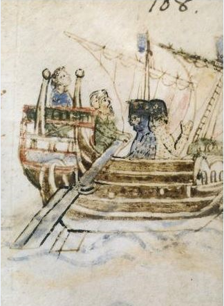
 Well, I've taken off that stringer behind the gunwale - I just wasn't happy with it. I'll find some other belaying method. In the meantime I've been doing some thinking about whether or not to have a calcet. The main problem is that pictures detailed enough to show whether or not a ship had calcets (or perhaps where the artist could be bothered to add that kind of detail) are usually 2 or more centuries after the ship I'm portraying. The pictures from which Woodrat got the calcets for his 14th century ship are admittedly only (only!) 150 years later, but that's still a long time for development to occur, and doesn't help with whether or not a ship from 1150 would have had them. But then I remembered the illustration from the Annals of Genoa (1173-1196) - perhaps only about 20 years after my own! It seems to me that there is something there at the top of the mast, of a different colour from the rest, and that the top is attached to the rear of it. It would have been nice to see what was happening with the foremast, but unfortunately this is all there is of the picture - the artist ran out of space at the edge of the page and left the rest off (fortunately, though, it shows a rope ladder, which the after mast doesn't). I think I'm going to take this as evidence for calcet, and act accordingly. Now it's a matter of working out a configuration for the calcet itself and how to attach the top to it. A bit of a diversion from building the hull, but I like to think things out in advance. I've now finished all the wales and the next step in the sequence should be either the deck beams or the planking. But I'm also thinking ahead to the configuration of the aftercastle/poop and also how the side rudders are going to work. Steven
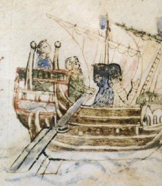

-
French person. Bienvenu, Thierry! It's totally ok to just sit on the sidelines and watch. There's a lot to be learnt from many of the build logs, as well as the discussions in the other parts of the forum. I'd particularly recommend the sub-section "Discussions for Ships plans and Project Research. General research on specific vessels and ship types.." Steven
-
HMCSS Victoria 1855 by BANYAN - 1:72
Louie da fly replied to BANYAN's topic in - Build logs for subjects built 1851 - 1900
I'd agree. Unless you really want to be that precise (and give yourself problems), I think notches would be the way to go. The sheaves themselves would be all but invisible anyway, as they would be mostly hidden by the pendant. Nice to see you back on the build, by the way. Steven- 1,013 replies
-
- 3
-

-
- gun dispatch vessel
- victoria
- (and 2 more)
-
Looks very good with the lights on, but perhaps there's too much of a good thing? Having lived by candle-light at times, I'd say you should probably go for rather less, and perhaps put some yellow/orange cellophane over your leds. A good example of the colour and intensity you should be aiming for is provided in Stanley Kubrik's movie Barry Lyndon in which all the interior scenes were filmed using only candle-light (with special cameras designed to do so). The castle itself is looking really good, though I can see you still have a lot of work ahead of you. Best wishes, Steven
-
It's quite possible that quinquiremes were relatively open at the sides, just like they built the trireme reconstruction Olympias - see post #126 here
- 290 replies
-
- 4
-
-
- Quinquereme
- Finished
- (and 1 more)
-
Agreed - it's not a wonderful idea to make your ship top-heavy, apart from the extra cost of the timber. But to me it just looks wrong. And there's no evidence either way from pictorial sources or archaeology as far as I know; most wrecks are found with their upper works missing - unless something has been found in the Black Sea that will clarify the issue. Steven
-
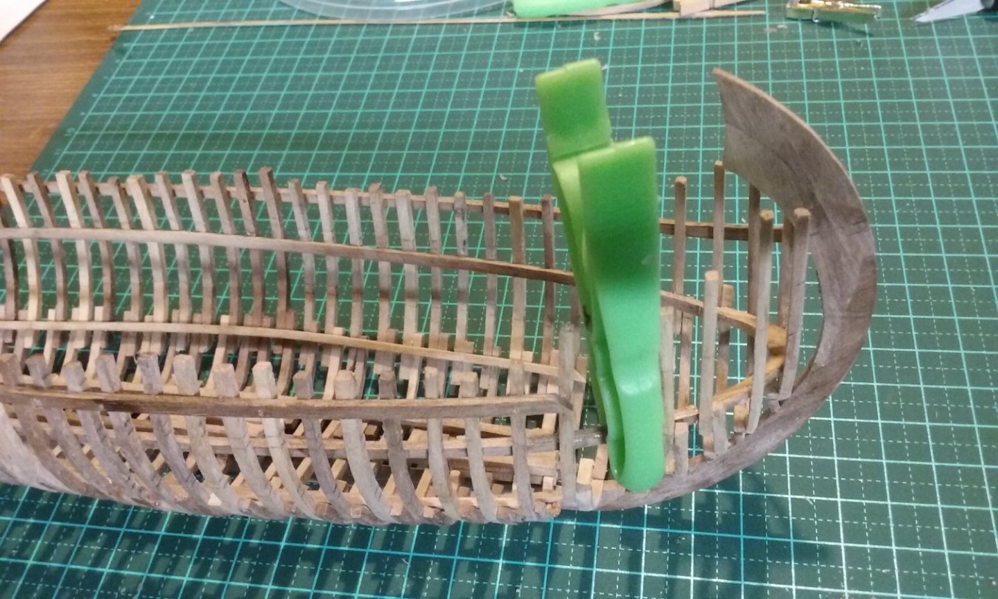
Finalising the gunwale, which hadn't quite reached the stempost due to a miscalculation. I glued in a couple of thin bits of wood to fill the gap, then trimmed them down to follow the line of the wales. I also curved the middle wales further upward at the bow, as the line was wrong. Now they form an intermediate curve between the gunwale and the wale below. Putting on the bottom wales - here's the first pair, at the bow. I hadn't bent them quite enough for the curve of the bow, but gluing them to the stempost and the first few frames will secure them enough to allow me to curve them around the "bend" by hand once the glue is dry, and tie the rest of the wale down to follow the rest of the frames. Another issue. To allow somewhere to belay the vertical lines, I added a stringer inside the hull in line with the gunwale. But I'm not really happy with it, and I think I might replace it with cleats or something of the sort, to perform the same function. What do you all think? Steven

-
That tail looks very good, and I think your decision was the right one. Regarding ventilation, I spent a lot of time pondering this issue during my dromon build. Without a time machine we'll never know the right answer, but the research suggests that adequate ventilation was vital for an oarsman to produce the effort required to row the ship. I never settled the problem fully to my satisfaction, as there was a contemporary account of it being "dark and gloomy" below decks in a dromon. I compromised by having gaps between every pair of deck planks for a large section of the decking. But a quinquireme is not a dromon, and would ahve a had a different layout. IIRC the Olympias was very open for air to enter. Steven
- 290 replies
-
- 6
-
-
- Quinquereme
- Finished
- (and 1 more)
-
I wouldn't worry to much about the "uniforms". Though there's pictorial evidence of a nobleman's followers wearing his colours as early as 1195, they weren't really a thing until the Renaissance. Judging by the figures and the bombard, I'd be putting them all in the 14th century (nearest timeline that includes both a bombard and the outfits of the warriors, though it's stretching it a little bit to do so - that's a very advanced bombard for those guys to be using). I think you've done a pretty fine job with such small figures. I think you're right putting mail rather than hair under the helmets, but I'd suggest the horseman (as a member of the wealthy class) should also have mail "stockings" (called chausses) on his legs. Steven
-
Have you seen the castle being built at Guédelon in France, using only traditional techniques? They've been at it for 20 years now, and it looks amazing. My wife and I are hoping to visit one day, and even perhaps lend a hand as unskilled laborers (sigh).
-
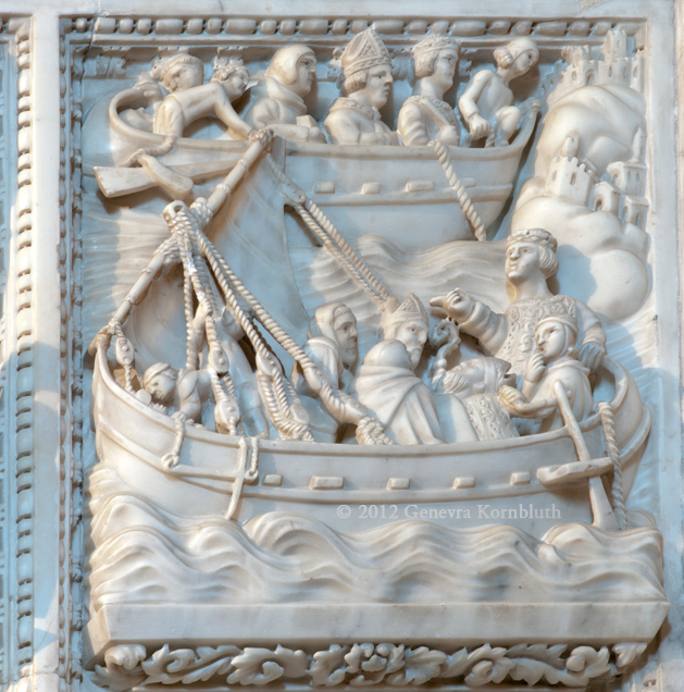
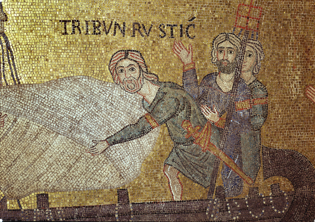
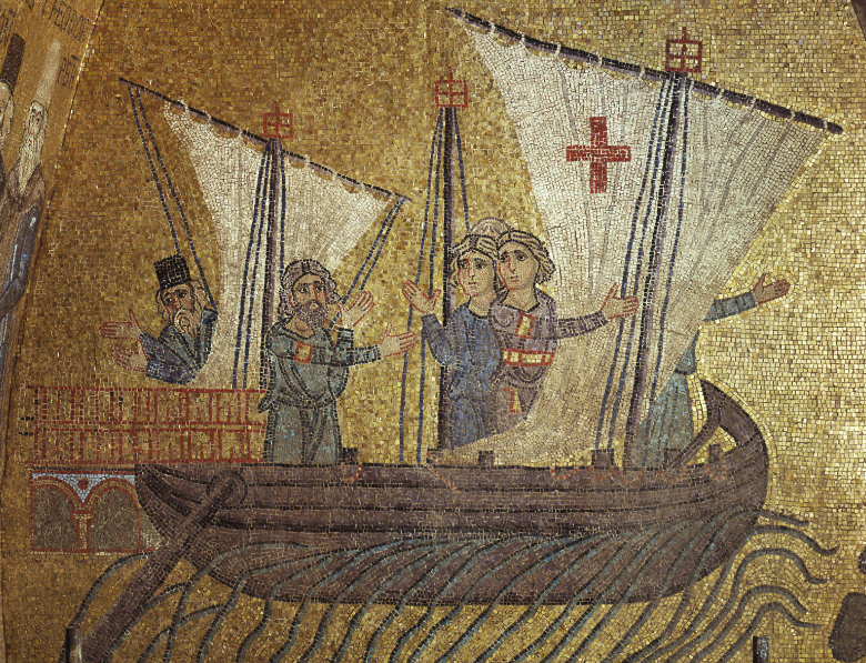
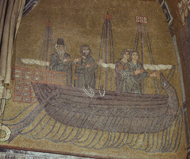
That was the way my own thoughts were going, Dick. Not jewels or pearls, but simply a colour that contrasted with the black hull. The only difference as far as I can see between the ones you've included above and the San Marco mosaics is that the ropes are looped over extended frames rather than randomly distributed, and I don't think there's any significance whatsoever in that difference. Steven
-
See sentence No. 2 in post #1 above. I wish I knew, but they do look very good. Steven
- 28 replies
-
- 10
-
-
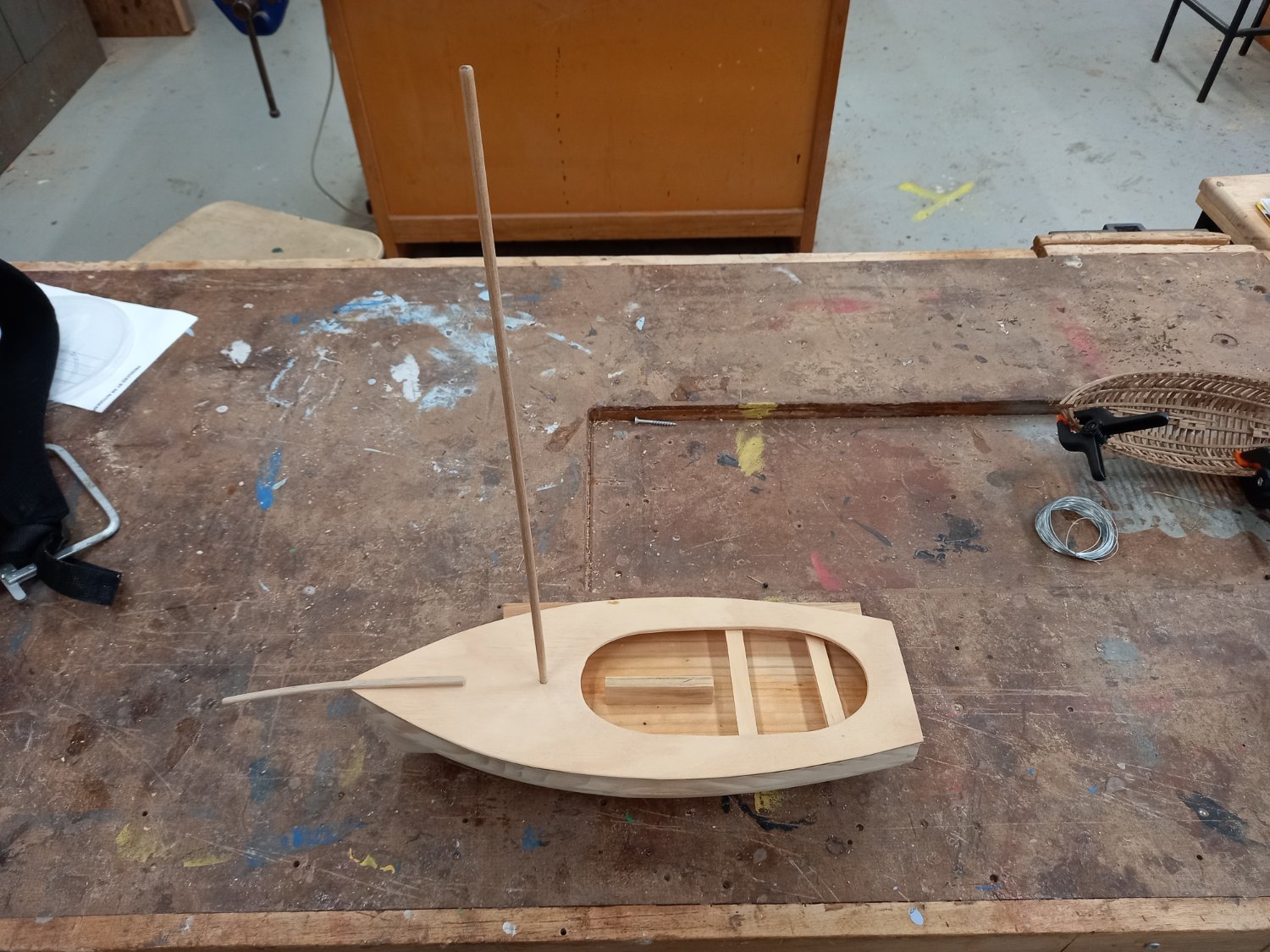
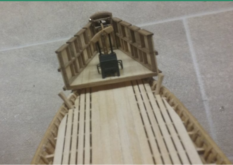
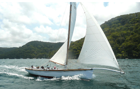
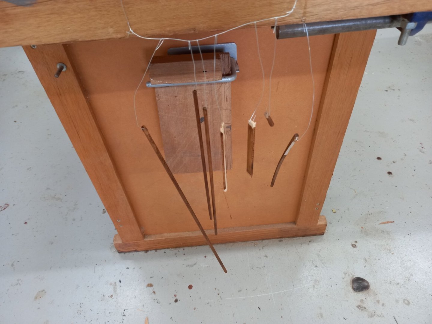
Couta boats have a very characteristic and rather attractive curved bowsprit. I had to do a fair bit of carving and bending until I got it right. Then the Men's Shed got a bunch of thin dowelling (about 5mm and 3mm) ideal for the mast, boom and gaff. Very pleasing. I also made seats. Here they all are dry fitted (except the boom and gaff, as I haven't yet made the fittings). And I got some old teak woodstain we had hanging around and stained these bits. Starting to come together nicely. Steven

- 28 replies
-
- 13
-
-
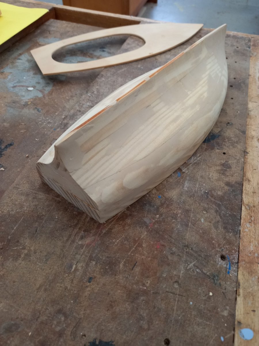
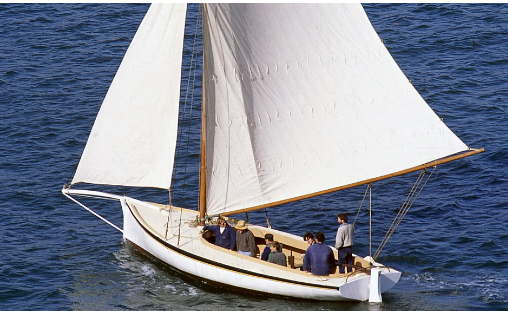
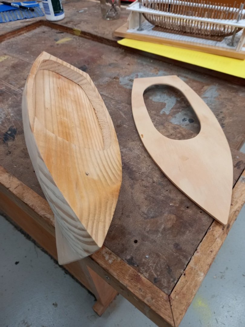
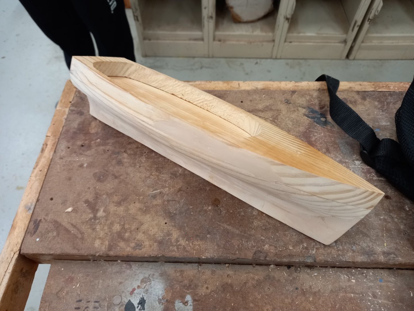
A couta boat is a gaff-rigged fishing boat used for catching barracuda in the State of Victoria, Australia, up till about the 1920's, being superseded by motor vessels, but many of them have been preserved and are now raced competitively. I wasn't going to do a formal build log for the couta boat, but I've changed my mind as i feel it's a worthwhile subject for a log. I didn't take photos at the beginning of the build, it's necessarily somewhat incomplete. Here are the first photos I took of the model. It was built up in layers and then sanded to shape with a belt sander. A lot of mistakes (it was the first time I'd used one of those things) but fortunately builders bog filled in where I'd sanded off too much, so she ended up looking pretty good. Steven

- 28 replies
-
- 16
-
-
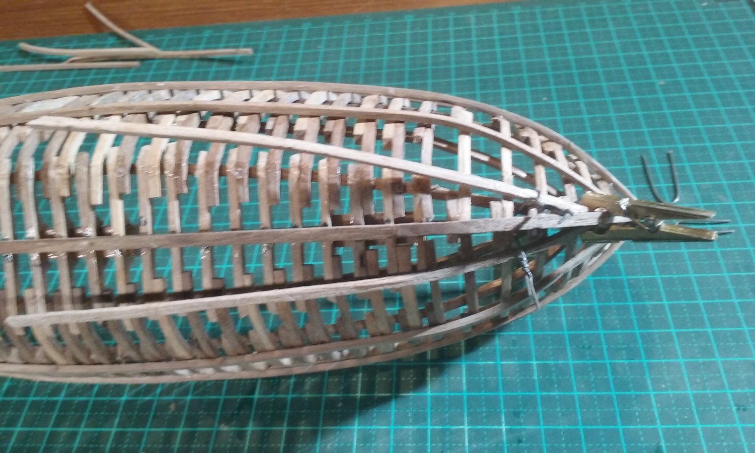
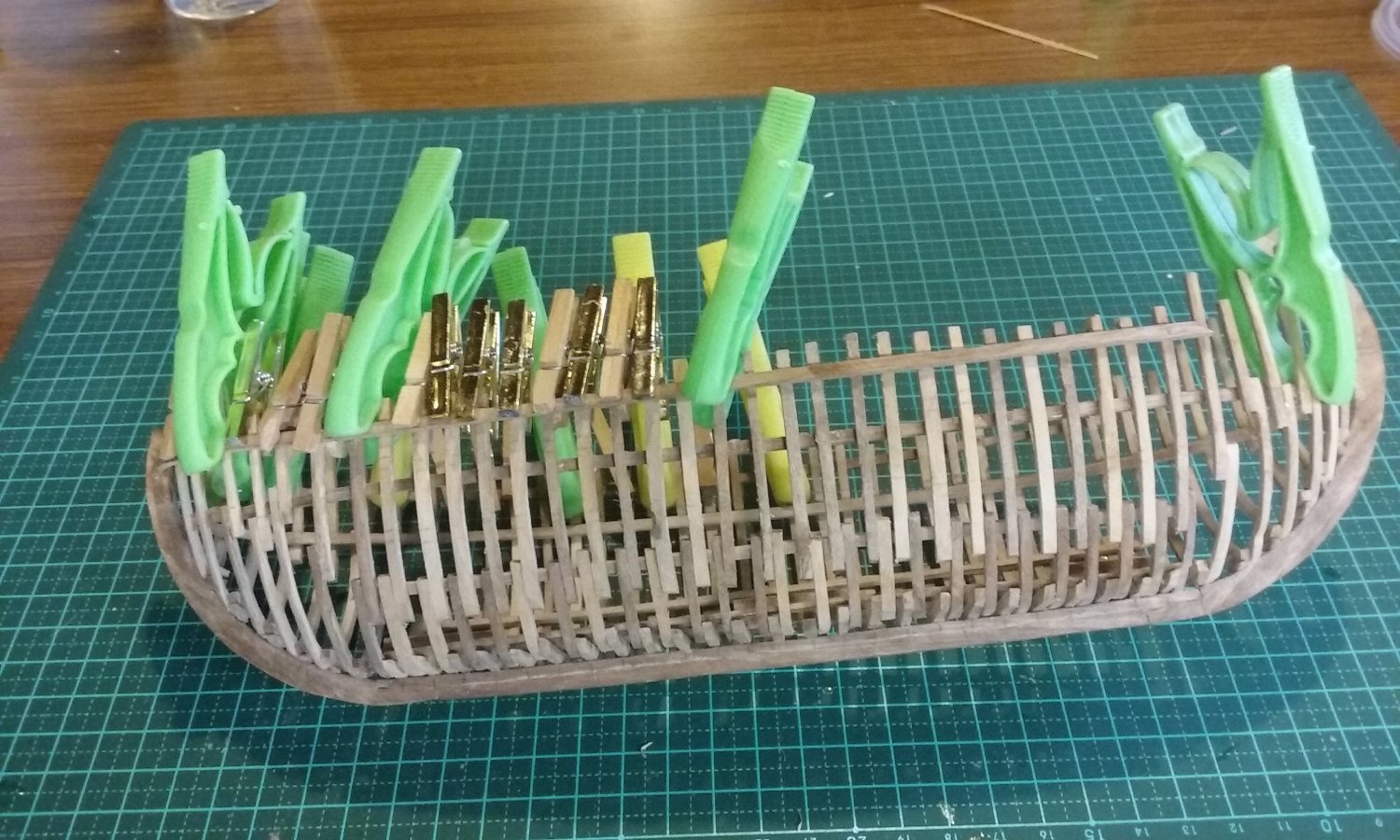
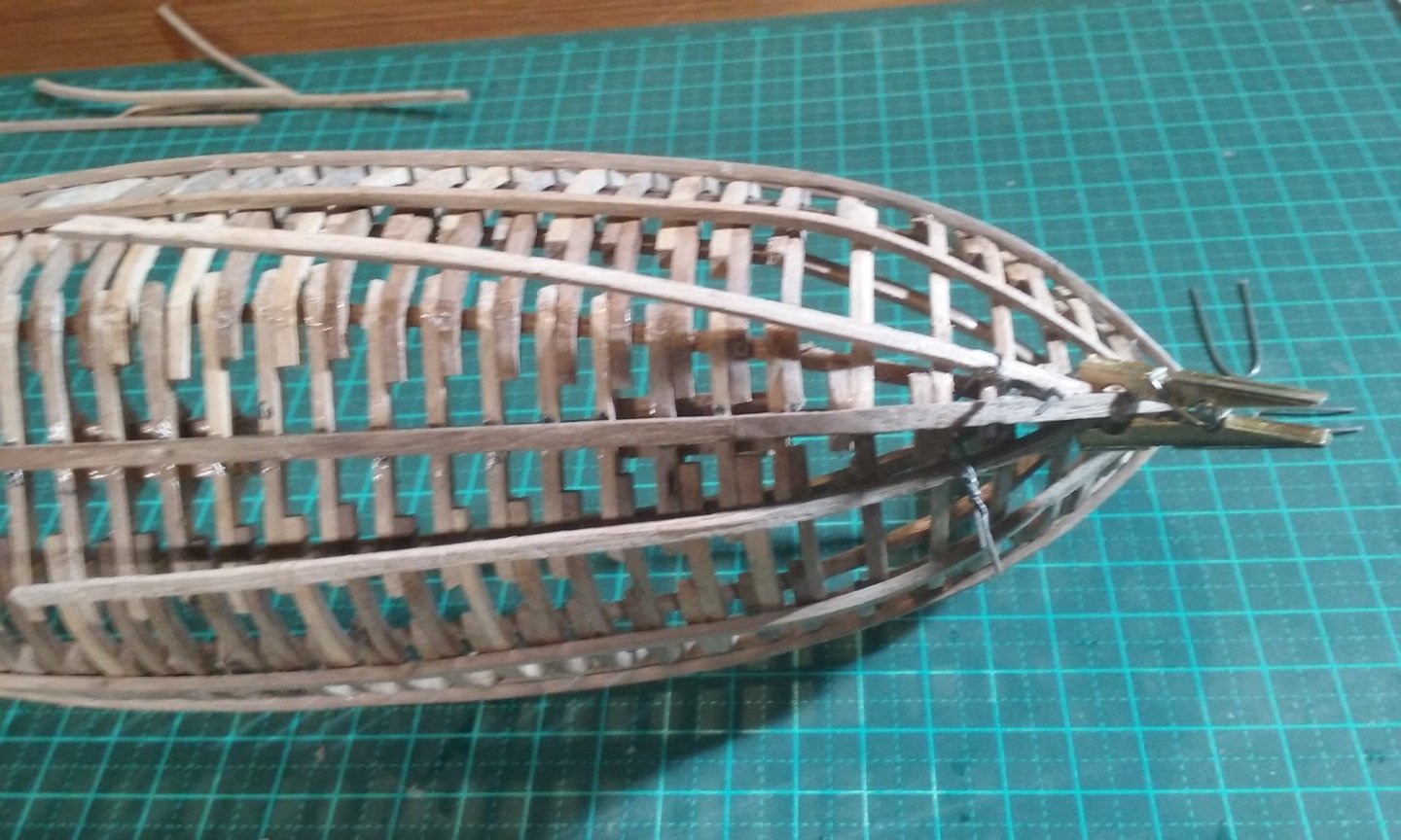
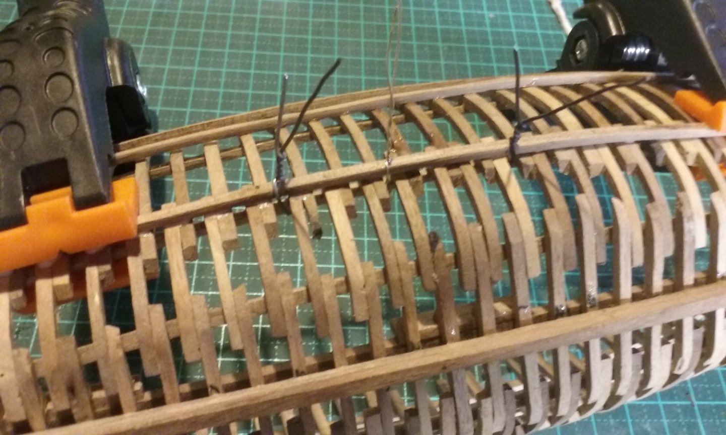
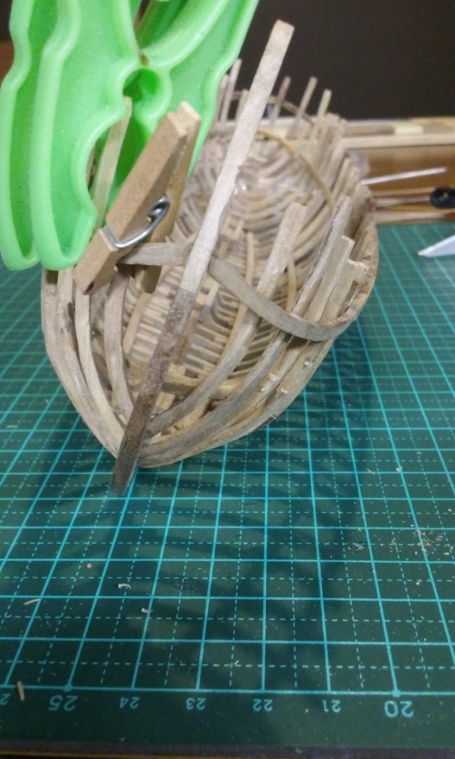
Leaving aside the discussion regarding the "beads", here's the latest progress on the ship. Adding wales in line with the stringers. The first starboard wale below the gunwale in place and the larboard wale clamped and waiting for glue to dry. And the clamps removed. Completing the stringers by adding the bits on the ends. And the second wale down from the gunwale glued and clamped. I only had two clamps that reached far enough, but my wife had a brilliant idea - use twisted wire as clamps. I had to be careful with this method to avoid the wire digging into the wood, but it seemed to work pretty well. It only works in very specific instances, but was ok here. Steven


- 508 replies
-
- 14
-
-
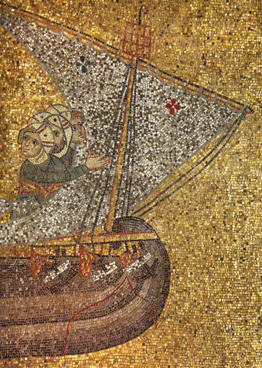
I've just answered it - I seem to be on this set of messages as well. Oh, yes. Two of my favourites - the ceremonial glove of William II of Sicily (BTW, have you seen the rest of the regalia? Just as amazing) and the mosaic in Hagia Sofia in Constantinople/Miklagard/Tsarigrad/Istanbul of Empress Zoe with her third husband, Constantine Monomachos - note that his name and face in the mosaic have been altered to update the husband! Thank you everybody for all the suggestions, but I'm afraid none of the suggested uses of these loops is convincing enough for me to include them as part of the model. I think I'll just have to put it down as "unexplained" for the time being. I'll keep an open mind and if I come across any other explanation all well and good. But for the time being, even though it seems to contradict the evidence somewhat, I think I'll keep the interpretation of them being coils of rope hanging from belaying points - they'd really only work for sheets and tacks, though, and I'll have to work out how to belay the vertical ropes such as shrouds and vangs (the rope controlling the top of the lateen yard - there's not really an appropriate English word for these as lateens aren't part of modern English usage. BTW, for a good representation of a calcet with a scarph joint to the mast, look at post #183 in Woodrat's Venetian Round Ship build log at Steven
-
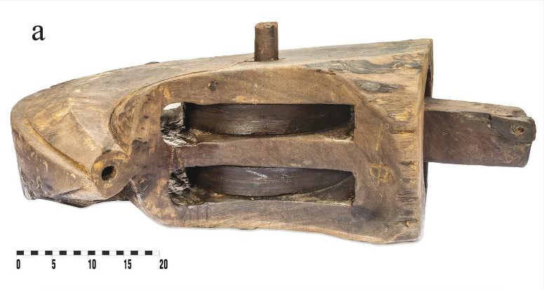
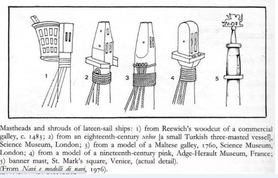
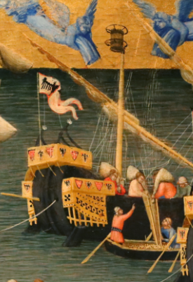
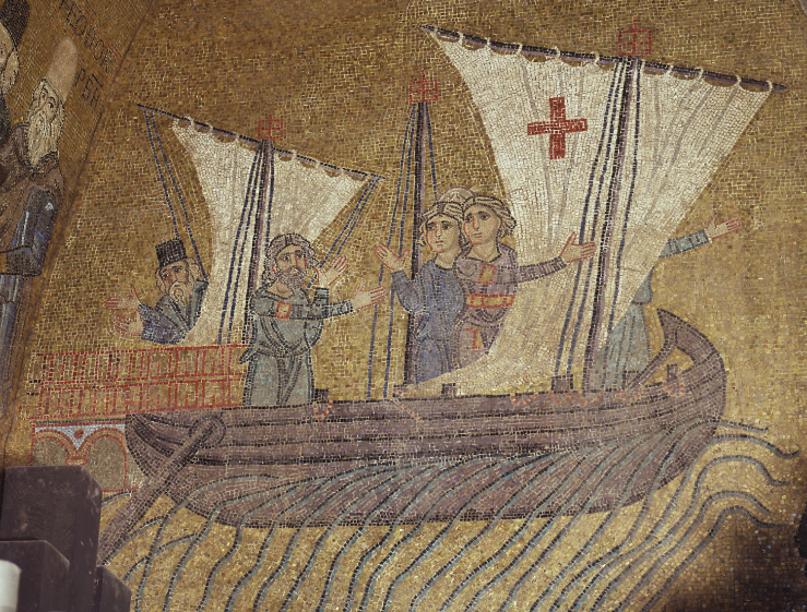
Thanks, but no need. I agree with you about the method of getting the halyard up to the sheave through the floor of the top - but Woodrat has made the point that a circular top around the mast would foul the lateen yard as it's moved from one side of the mast to the other, as the vessel tacks - see our exchange of 24 July in this build log. It's very likely the mosaic artist has got this wrong and that the top is mounted behind the mast, in which case the halyard would be handled differently. See illustration No. 1 below (my thanks to Woodrat for this one) for the likely configuration. Probably the mosaic artist saw and misinterpreted something like this (1332-34, St Nicholas' Miracle of grain ships by Ambrogio_Lorenzetti. Uffizi gallery, Florence), but probably without the metal rings around the top. On late mediaeval and renaissance lateeners there was a removable piece called a calcet that was mounted - usually with a scarph joint, as you suggest - on top of the mast, to take the sheaves of the halyard. There's a good example in Woodrat's "Venetian Round Ship" build. But the earliest pictorial evidence we have of calcets in the Western Mediterranean is from about 1300, 150 years after this ship, which made me consider the possibility of incorporating the sheaves within the mast itself, particularly with this picture (from the Church of San Pietro in Ciel d'Oro, Pavia, 1362 C.E. ) as a guide. On the other hand, the Ma‘agan Mikhael B wreck of 648 - 740 C.E., a 25 metre merchantman found just off the coast of Israel, had a fully preserved calcet. So perhaps I should be going with a calcet after all - let's face it, the Mediterranean was a place of great cultural exchange throughout the centuries, and something as obviously useful is likely to have been - and remained - in widespread use. Steven
-
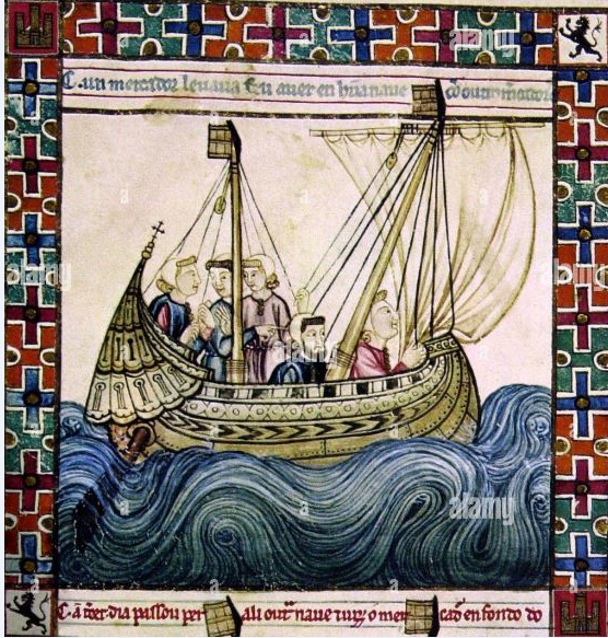
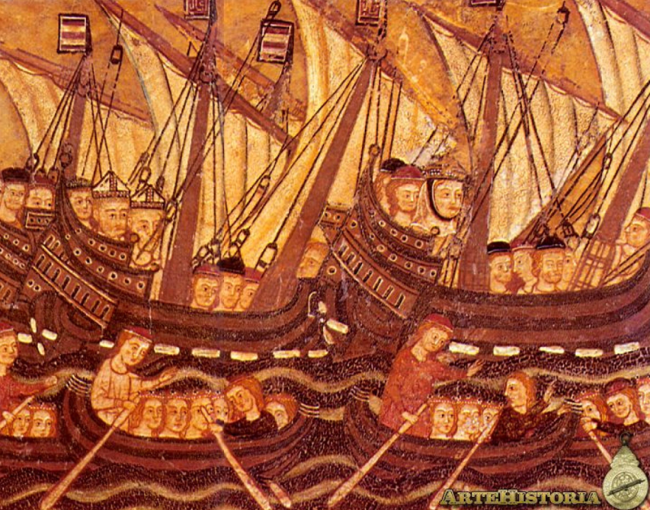
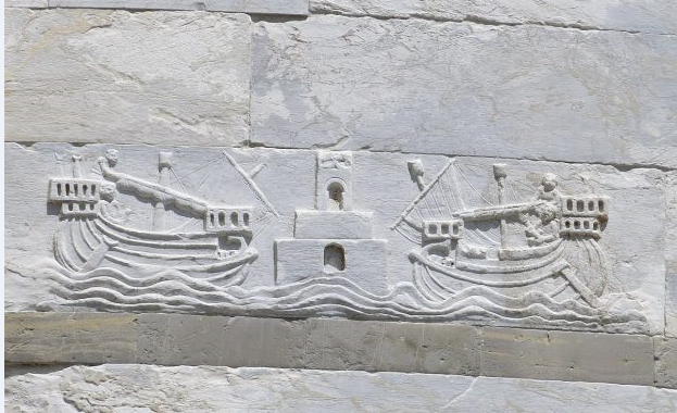
You could be right, Mark. But we're completely in the dark at this distance in time. I've tried to find any and all miracles attributed to St Mark, and there are quite a few, but none relate to these loops. Now, on the surmise that (a) these uprights are extended frames rather than the tops of kevels (or more likely cleats, as in my understanding kevels were a relatively late development), and (b) they're belaying points, then they couldn't be used to belay the bottoms of the shrouds - being vertical, they'd just slip off again. So, if they are part of the rigging system, they must be used to belay the running, rather than the standing rigging. I incline to this view, though I have absolutely no real evidence to back this up. Unfortunately, there are absolutely no 12th century pictures that show how the shrouds or the running rigging are belayed - they just show lines coming down from the masthead and ending at the ship's side, and you're often lucky to get any running rigging at all. The earliest I've seen that show any detail of this kind at all are from the 13th century Cantigas de Santa Maria, from the reign of Alfonso the Wise of Castile (1252-85). The picture below is the best example, and and even this is pretty hard to make sense of. Apart from being at least 100 years too late, it's also from Spain, not Italy. The next earliest that shows any sort of rigging detail is an illustration from the legend of St Ursula in the Church of San Francis de Palma de Mallorca, from the 1st quarter of the 14th century- and again it's from Mallorca at the western end of the Mediterranean, under Spanish control. At least the rigging of this one makes some kind of sense - the lower shrouds end in blocks that are belayed to the hull - probably to the inner sides of the bulwarks, and the yards are controlled at their after ends by blocks. The fore ends aren't visible, but I'd guess they're each held by a pair of blocks, one belayed at each side of the ship, the weather one slack and the lee one hauled in. This will all be useful when it comes to rigging the ship further down the line, but it really doesn't solve the issue of exactly what those uprights are . . . Steven
-
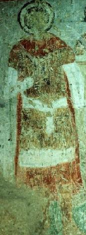
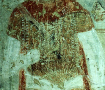
Well, yes. This is one of the reasons I put this issue up for discussion. On the other hand, the Venetian mosaicists were working within the tradition inherited from Byzantium, in which religious motifs and figures seem to have pearls added wherever possible. See the figure below, one of a series of military saints in a fresco in Kapadokya, in what is now Turkey but was then the heartland of the Byzantine Empire. A close-up shows this armoured figure has what appear to be pearls all over his outfit - most impractical in combat! So it's possible these are ropes converted to pearls as added decoration, rather than something in the real world. This perhaps ties in with Knocklouder's suggestion, or perhaps not. But my other concern is that as Banyan has pointed out, they're just loops, apparently not connected to anything in particular. Plus the fact that they're draped on the outside of the hull, not on the inside of the bulwarks as we would expect if they were rigging ropes tied off. Thanks for the suggestions so far. If anyone else has any possible explanations, I'd be happy to hear them. Steven
-
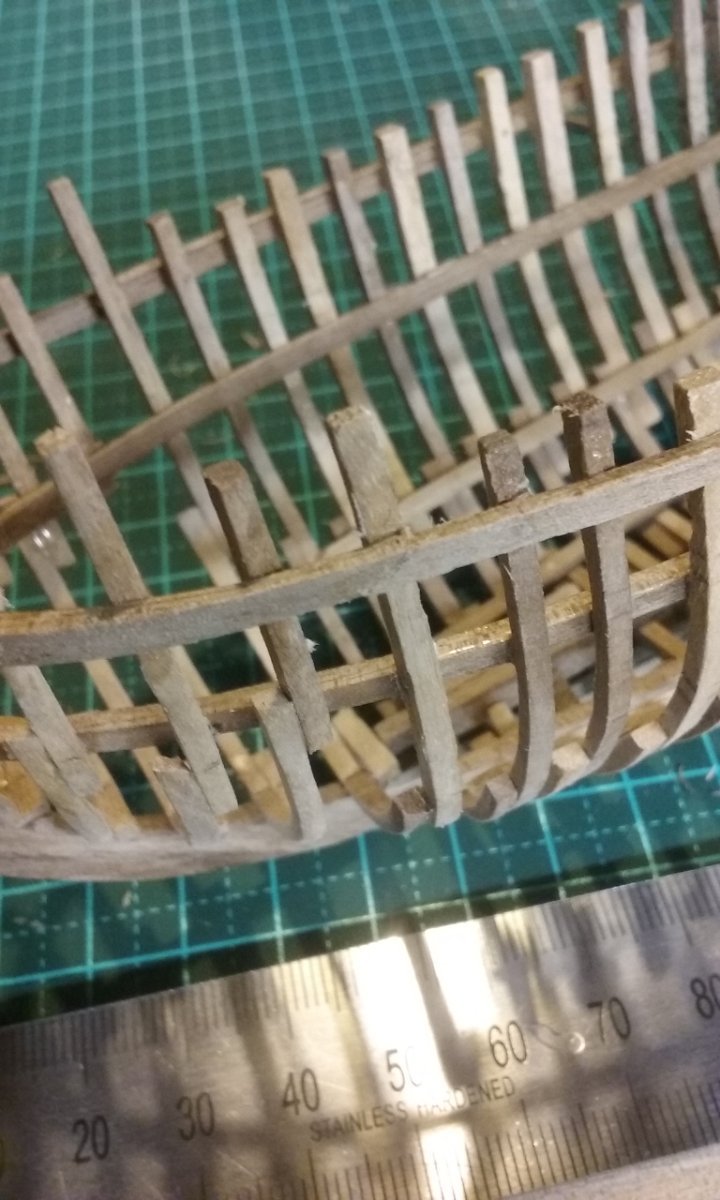
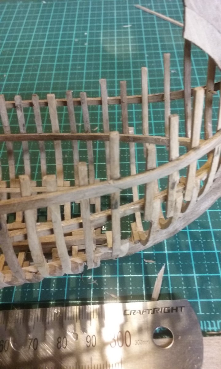
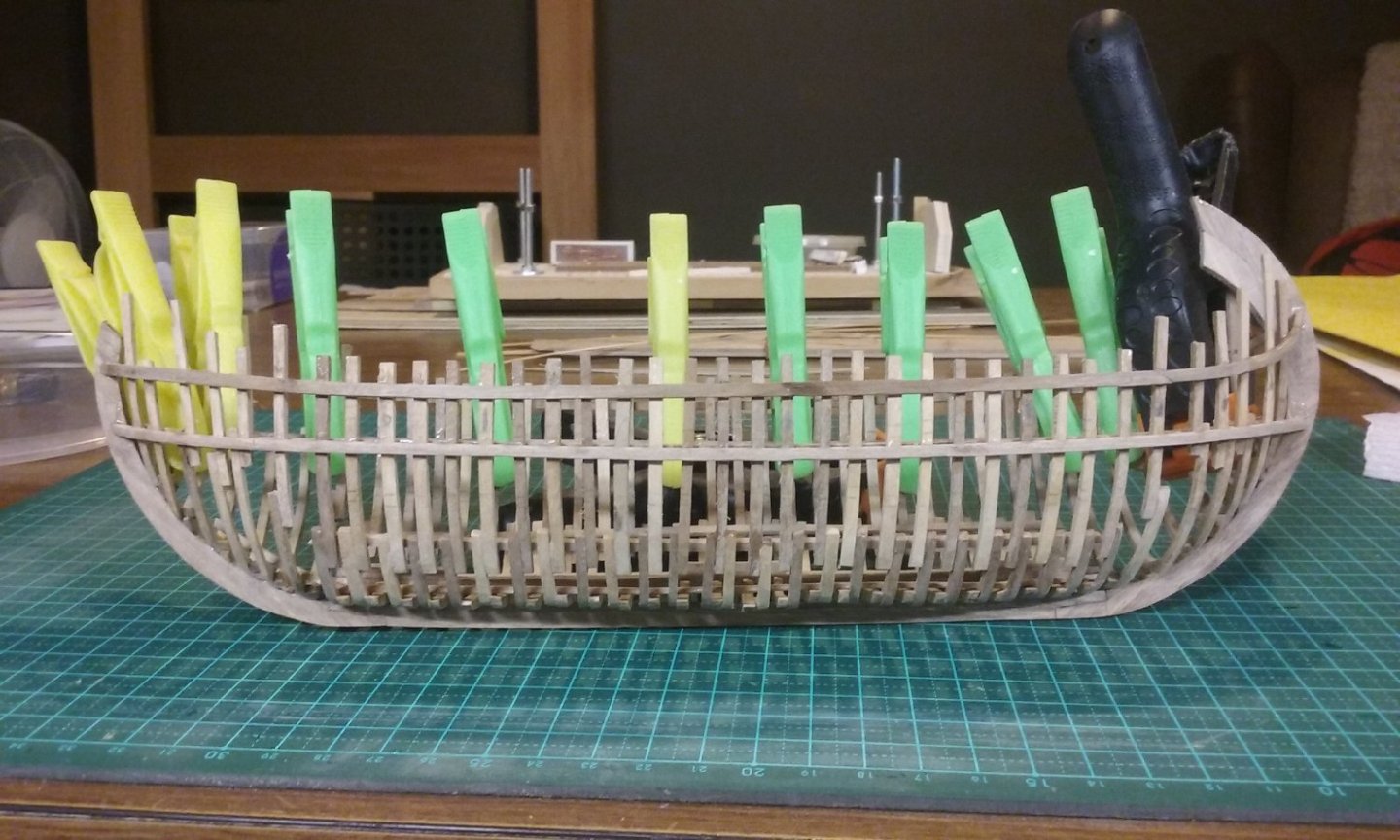
I have a bit of a quandary. Most of the mosaics show uprights extending up above the gunwales. They appear to be frames that haven't been cut off flush with the gunwale, and there are what appear to be rope loops (unless they're string of pearls - anything's possible in a religious mosaic!) hanging from most of them. I'm assuming they're belaying points. Do the members agree with my interpretation, or are there any other possibilities that come to mind? Steven PS: I've just noticed that the last picture shows three (three - count them!) anchors at the bow of the ship - and that's just on the starboard side! This makes sense. As I discovered researching my dromon build, anchors made by hand by a blacksmith on a forge were pretty limited in size and therefore in weight. You'd need quite a few - the 11th century Serçe Limani Shipwreck had 8 of them, of which 3 were reportedly bower anchors.
-
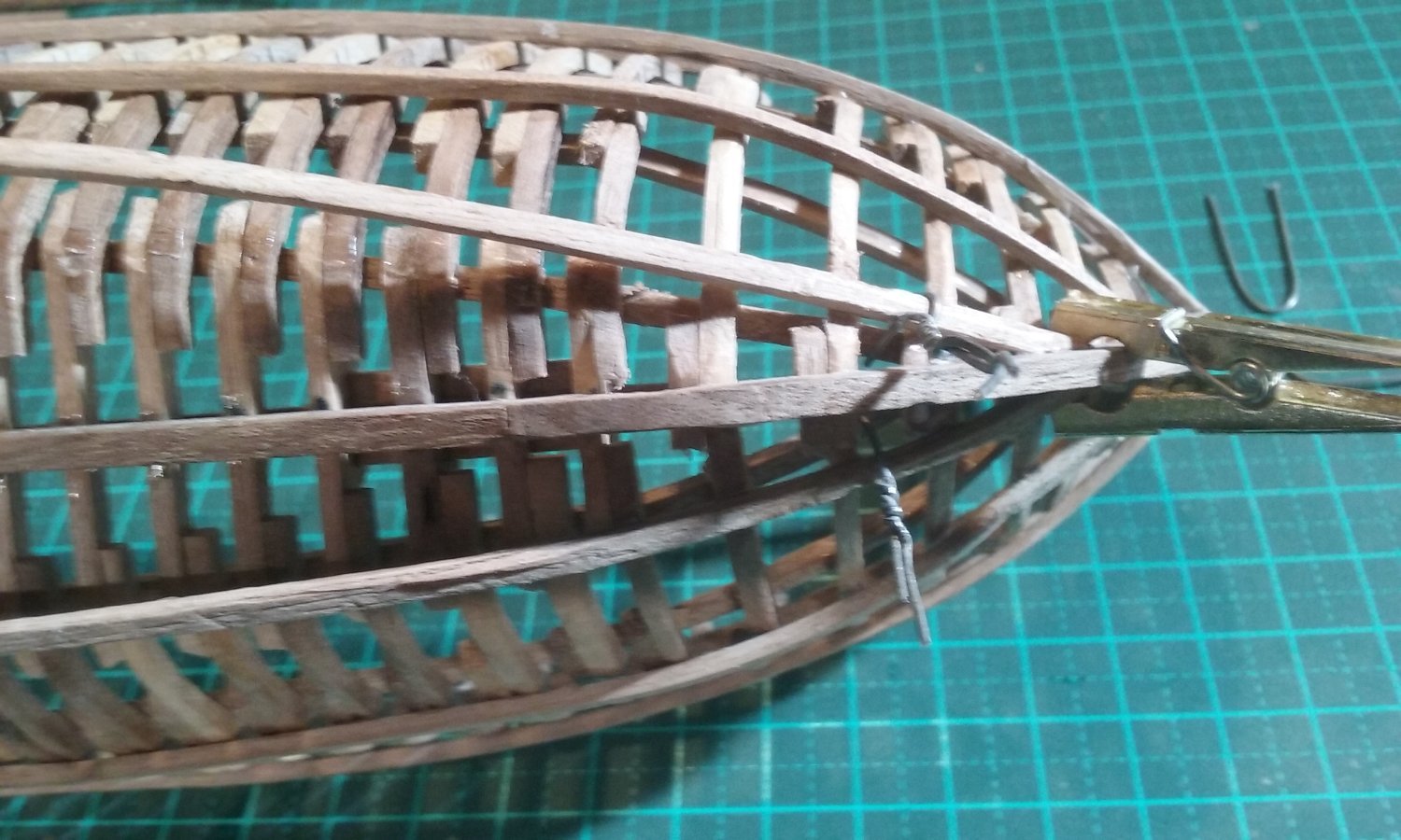
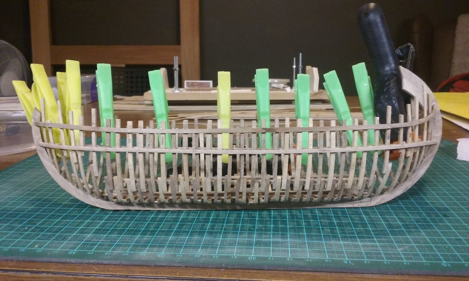
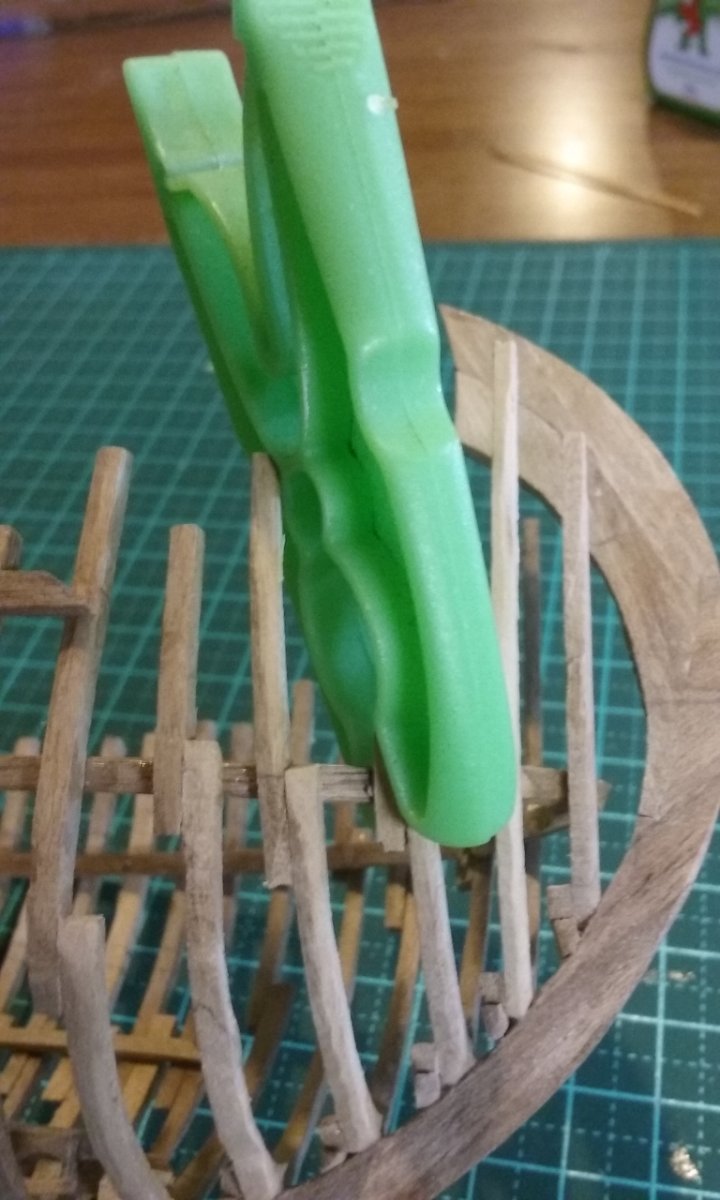
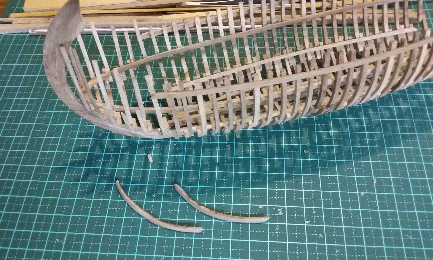
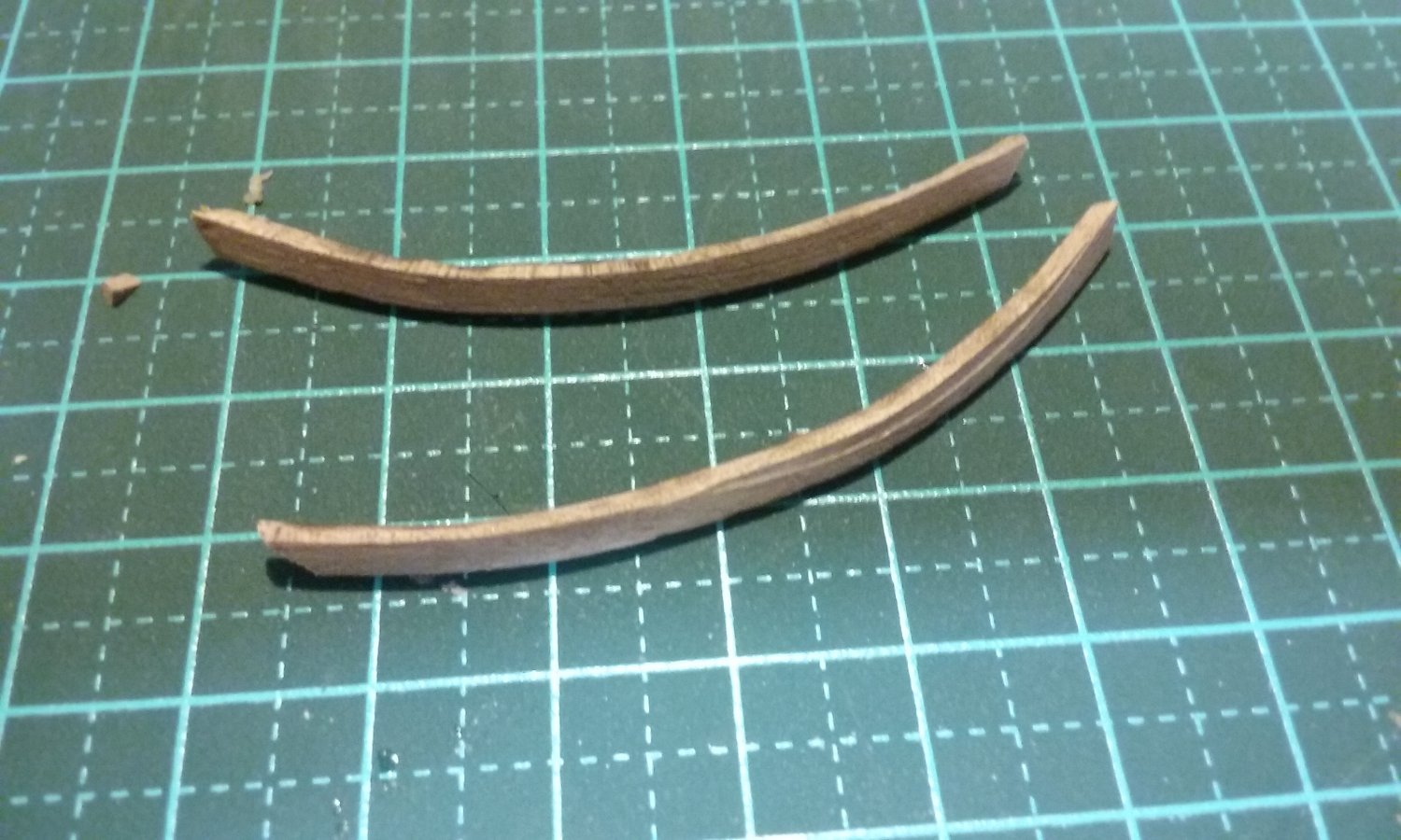
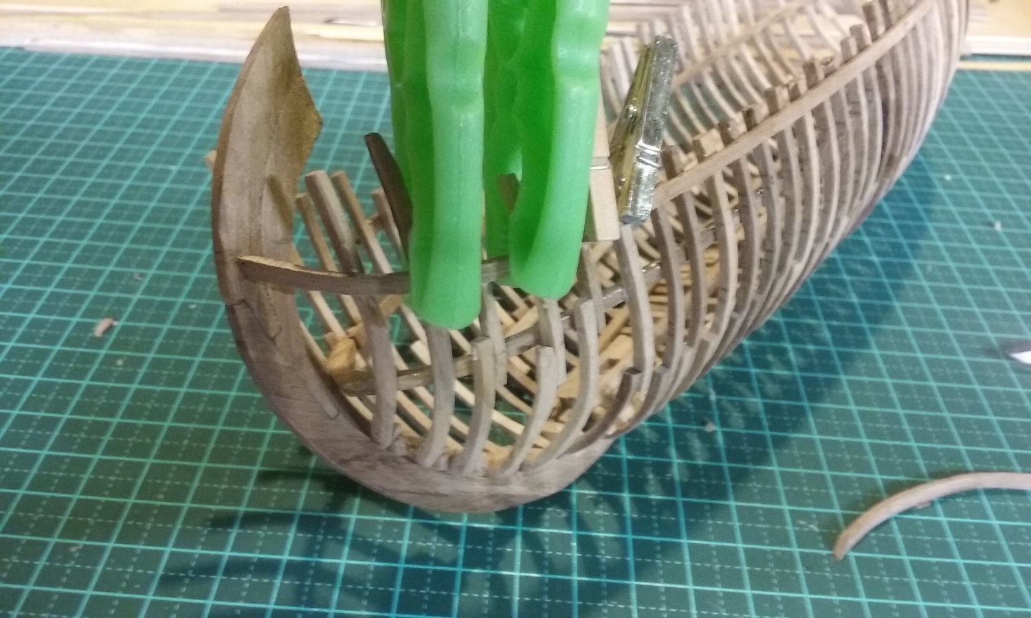
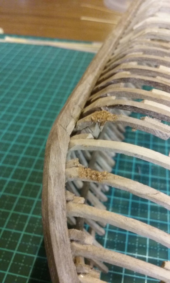
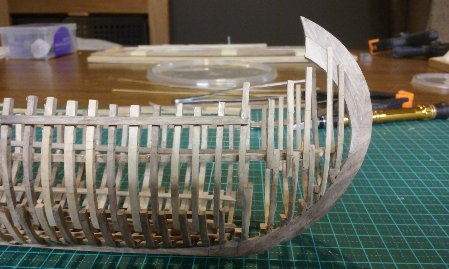
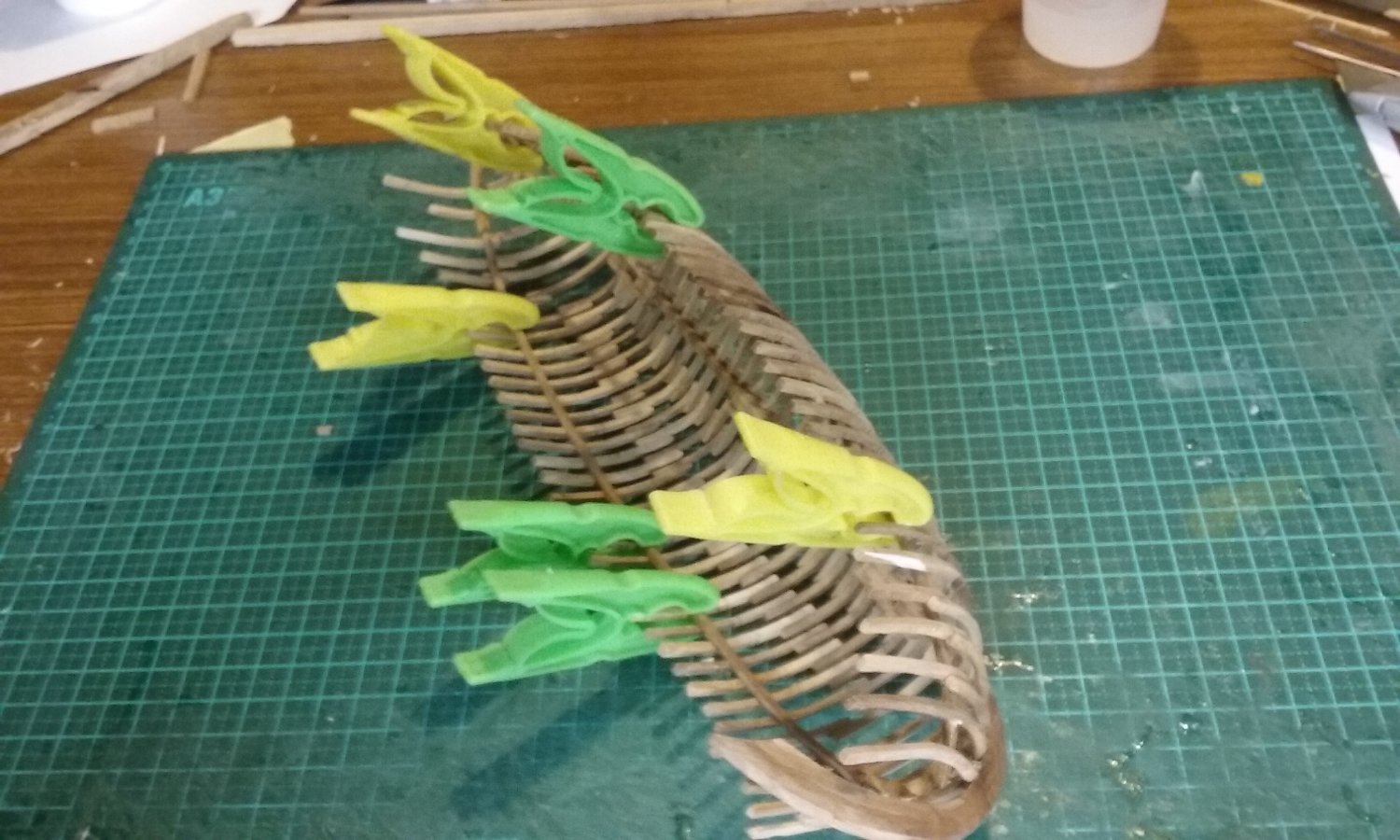
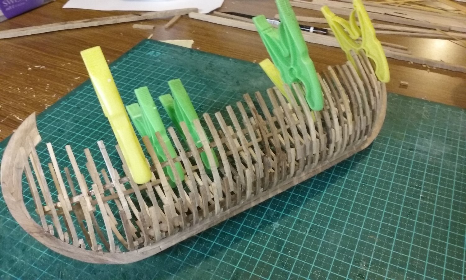
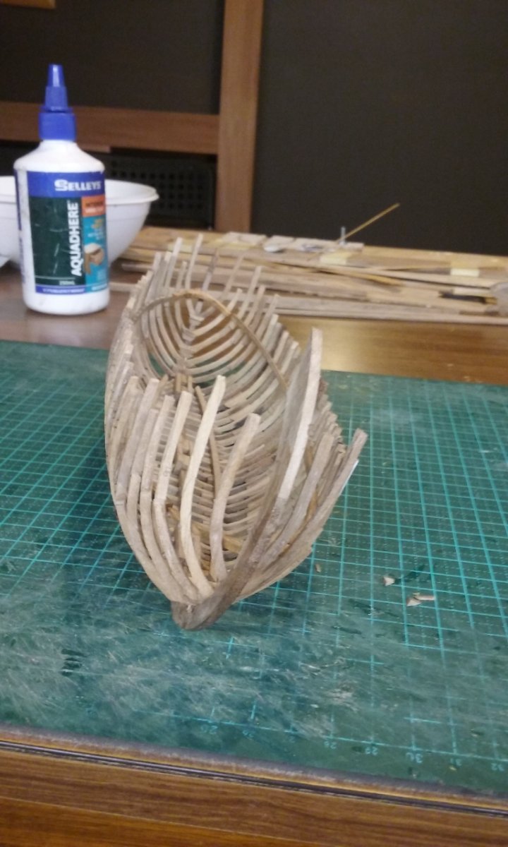
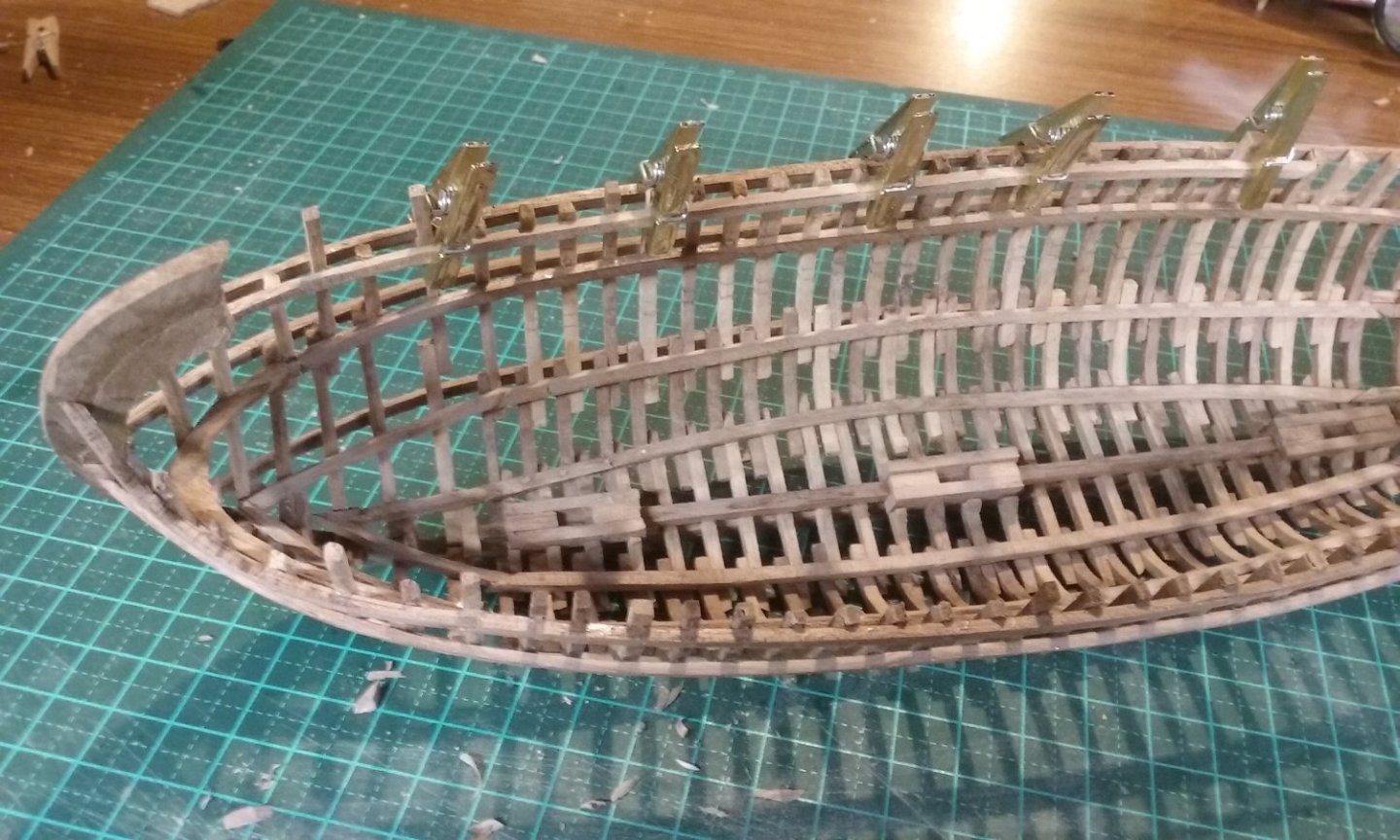
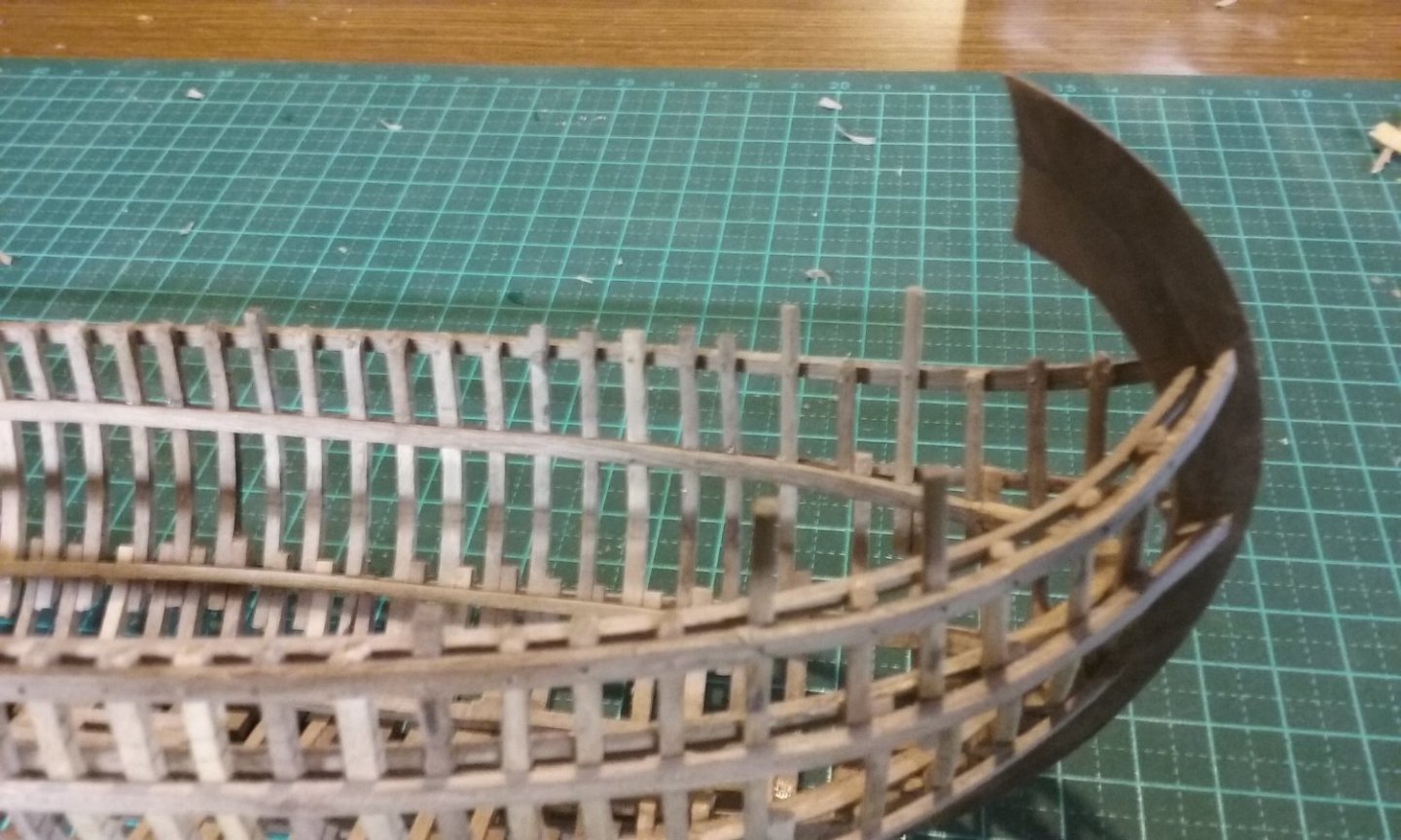
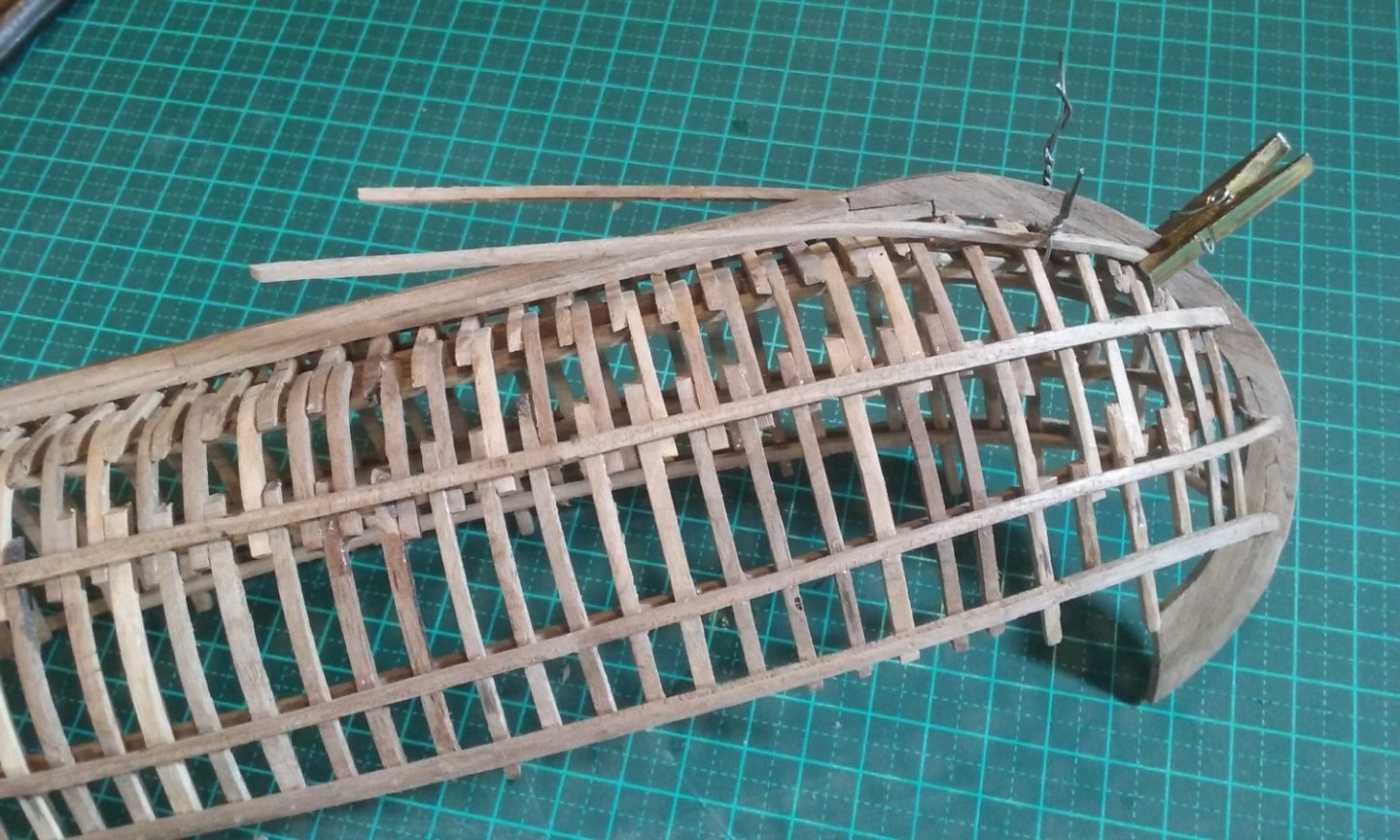
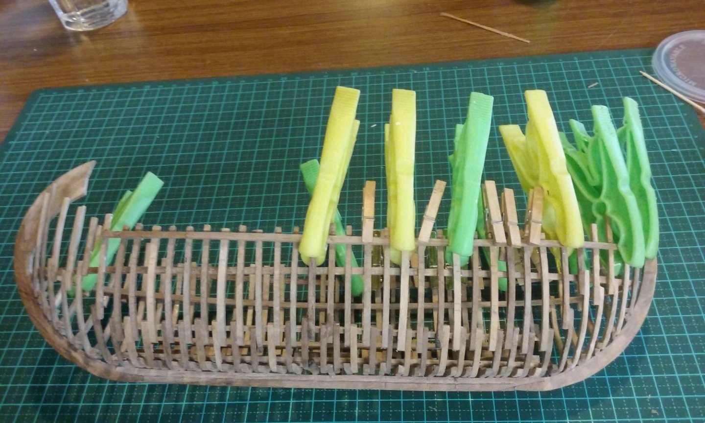
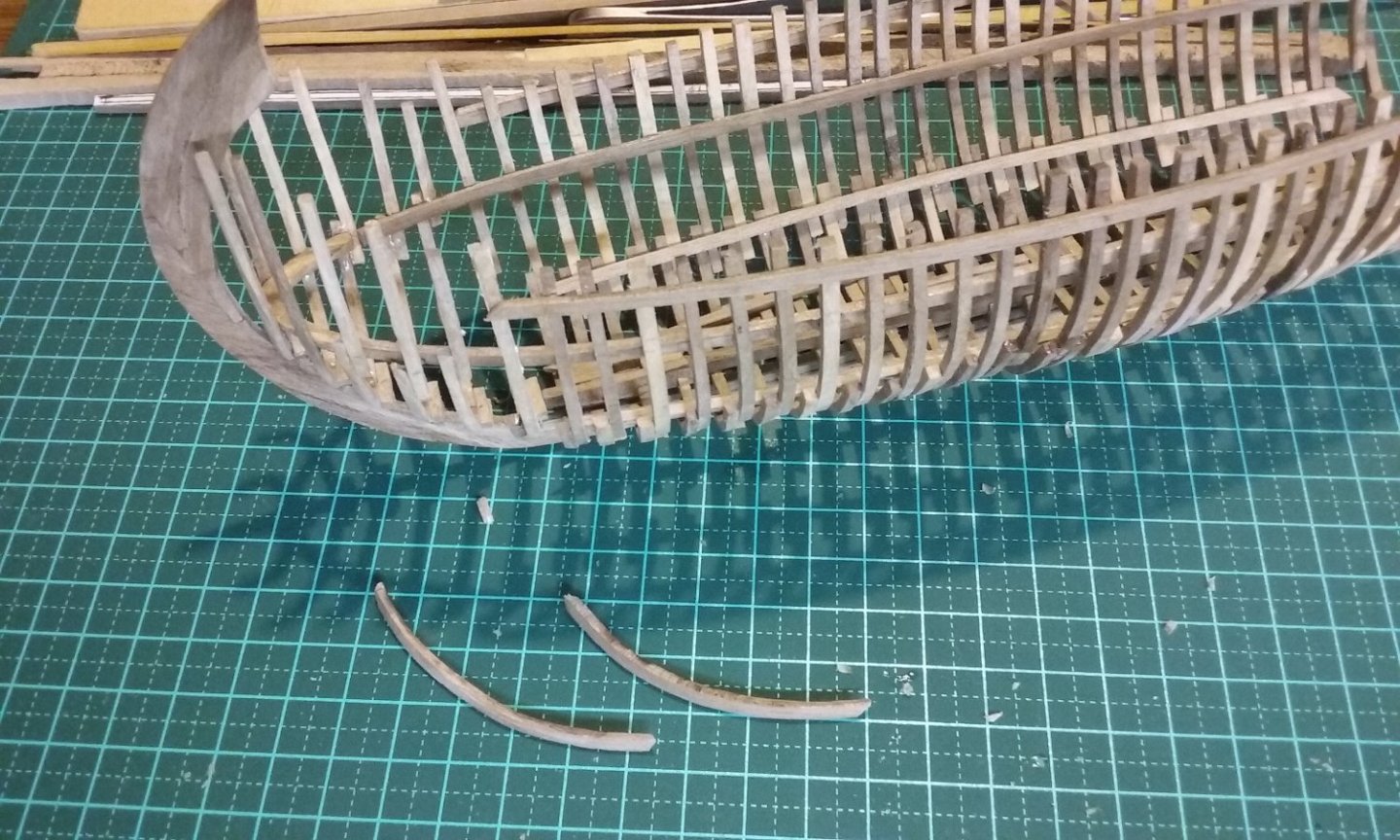
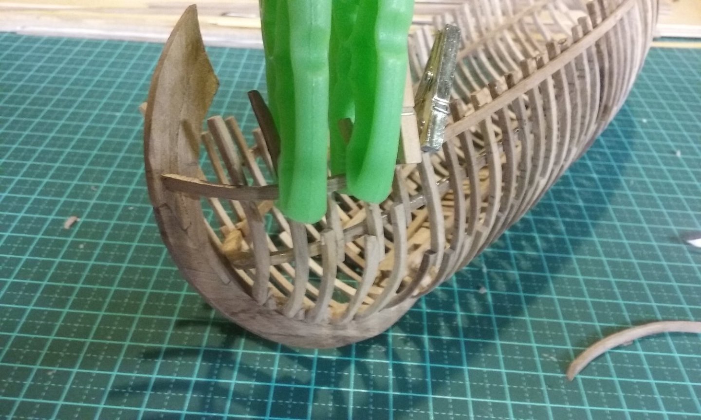
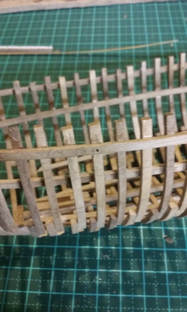
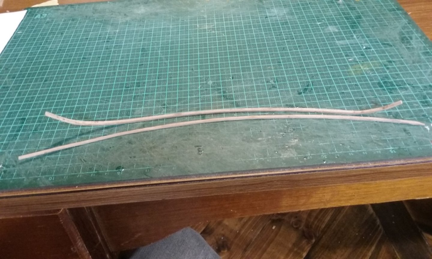
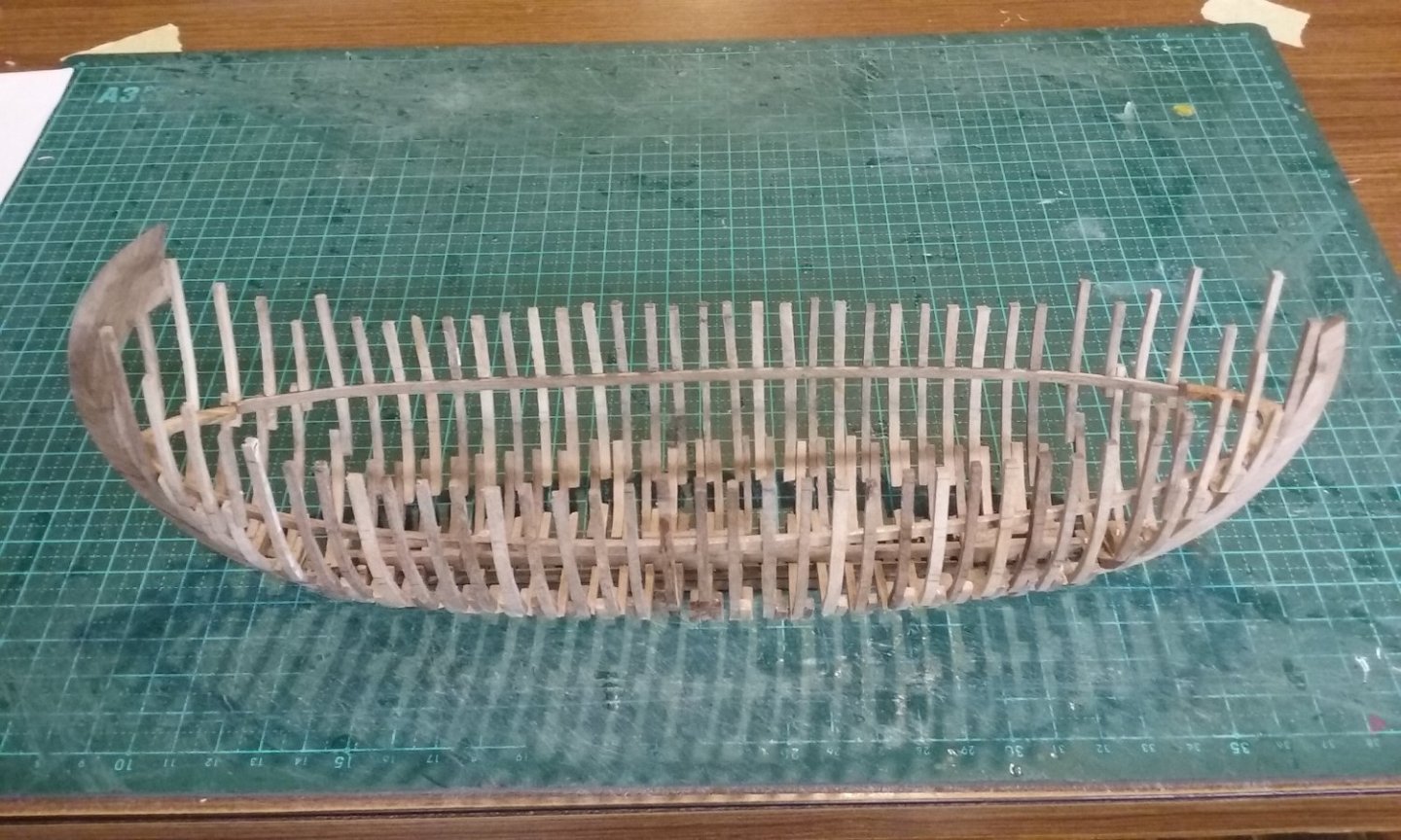
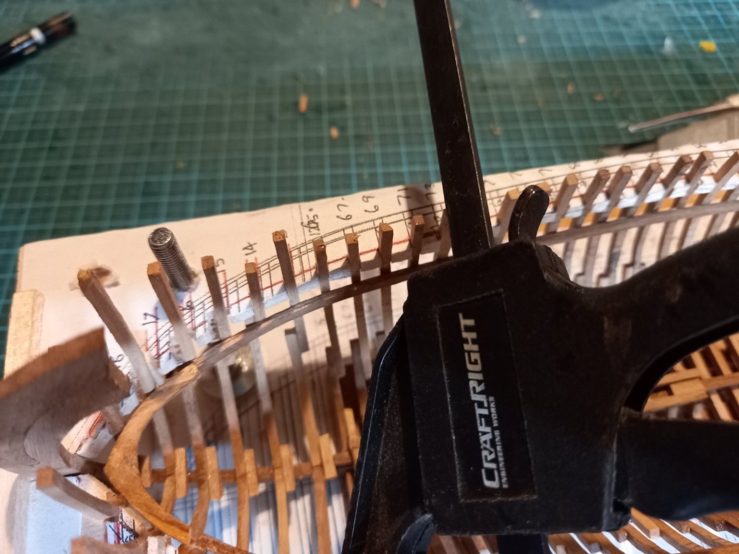
I decided it was time to add the gunwales. They add to the strength of the hull, tie down the upper edges of the frames, and also define the shape of the vessel itself. The biits of wood I'd cut them from weren't long enough to stretch the full length of the hull, but that turned out to be a good thing, as the gunwale kicks up quite a bit at the bow, and it's easier to make that piece as a separate item. I discovered that one of the frames at the bow had come away from the breast hook, so it had to be glued back into position. This seems to be happening a lot. Here are the two gunwales seen end-on at the stern. And here are the end pieces of the gunwale to go at the bow. And the larboard one glued and clamped in place. To overcome the problem with frames coming away from the clamps, I started drilling holes and inserting treenails at intervals. I'm hoping I don't have to do this with all the frames, but if it's needed I will. Here's a hole drilled joining frame with gunwale. I began with bamboo toothpicks when I was pinning the frames to the keel, but once I got to the gunwales I changed to walnut to match the rest of the ship - I don't want my treenails to be obvious - I don't believe they were visible in the real world (though it's not all that important - the ship's going to be painted black anyway, to make it look like it's tarred.) If you look carefully you can see the treenails (not yet trimmed flush with the gunwale) Once I'd faired the frames I discovered I'd been a bit too enthusiastic with the disc sander in places, so I had to add some filler to bring the frames back up to the right shape - fortunately not many times, Bow ready to receive the extension to the gunwale. Extensions in place. They line up nicely. I'm quite happy with their consistency - I think I'm getting better at bending. Joins between the gunwales and the extensions - I'm getting better at scarph joints, too. More to come in due course. Steven


-
Very nice. Work. I'm enjoying following this one. Steven
- 134 replies
-
- 3
-

-
-
- sea of galilee boat
- SE Miller
- (and 1 more)
-
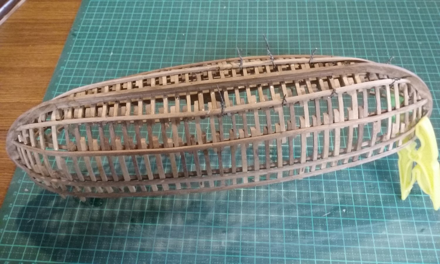
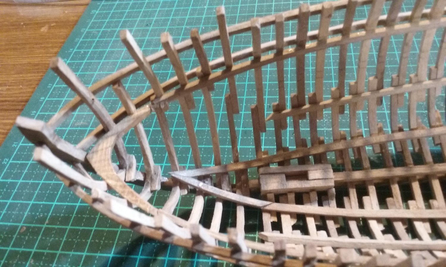
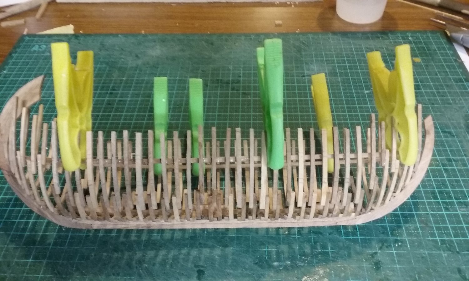
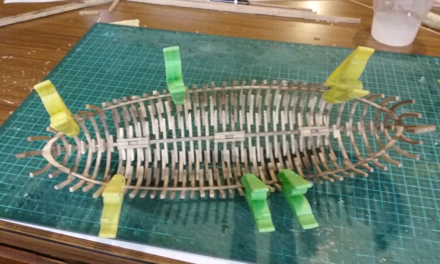
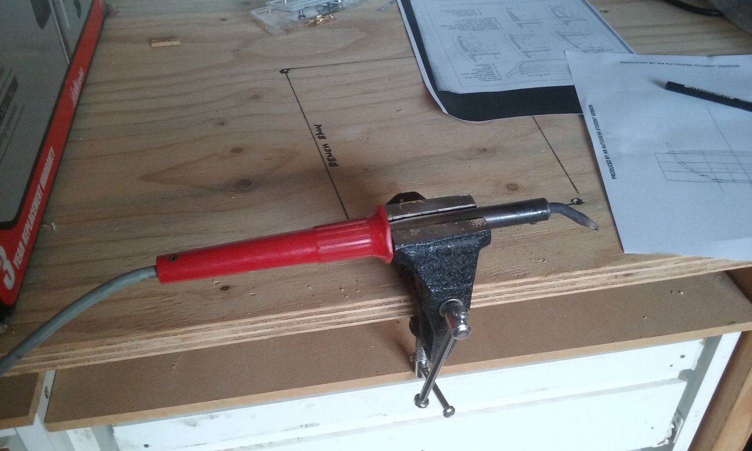
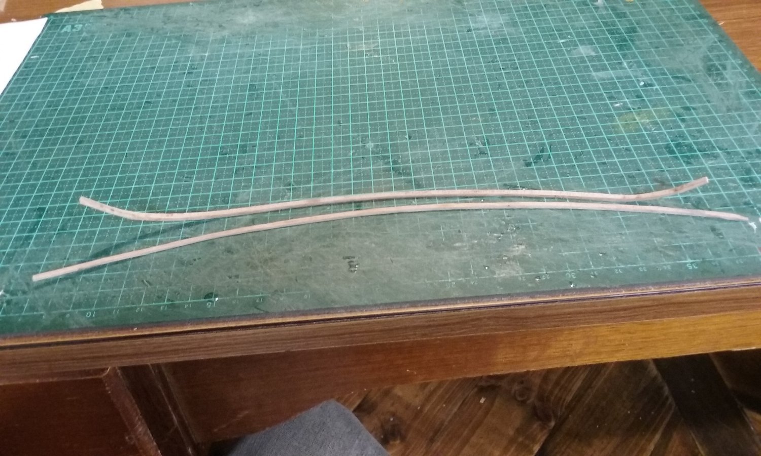
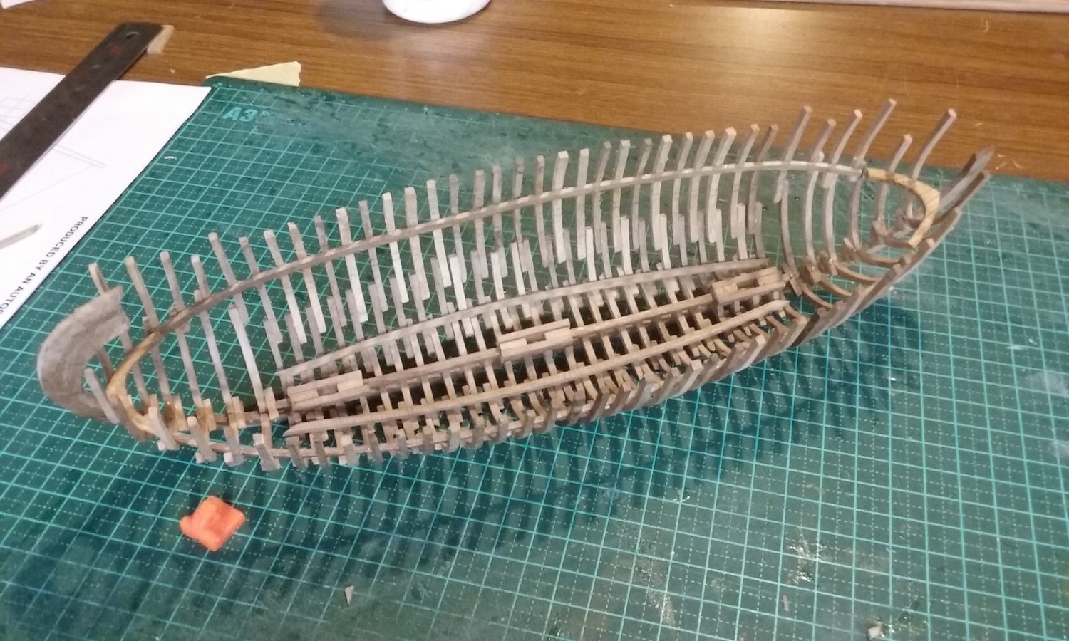
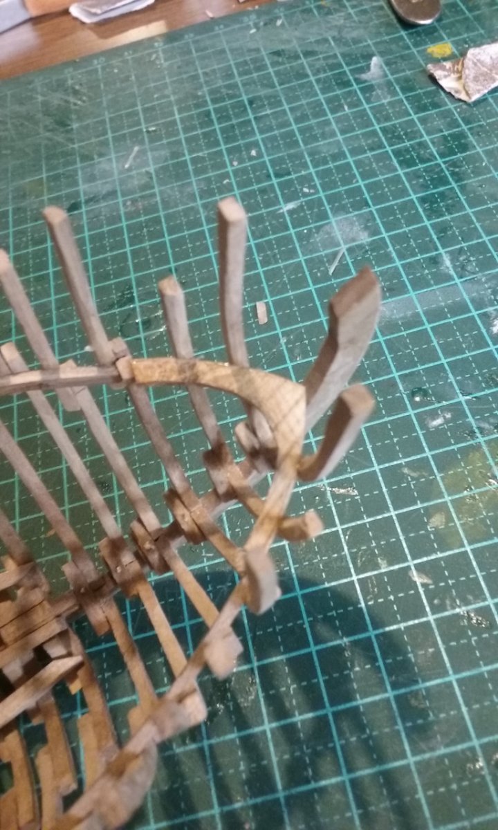
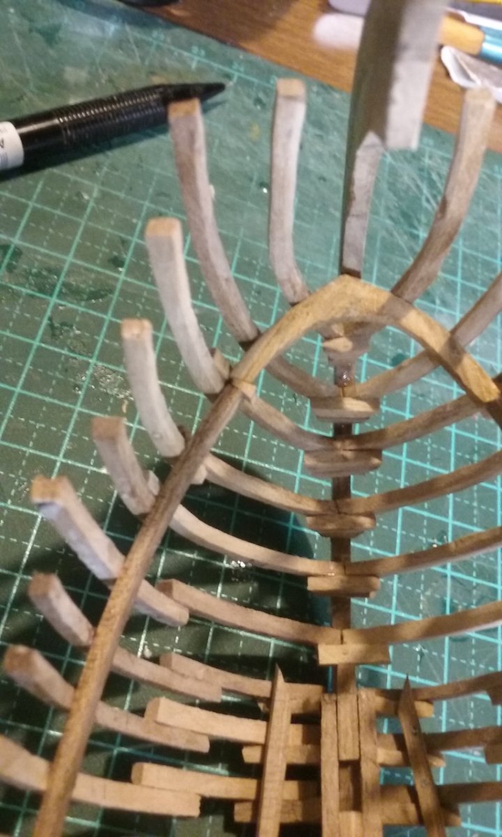
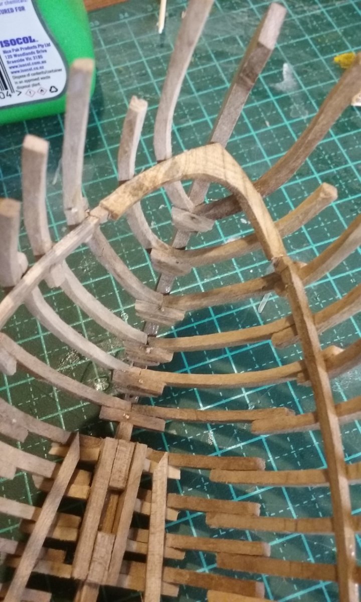
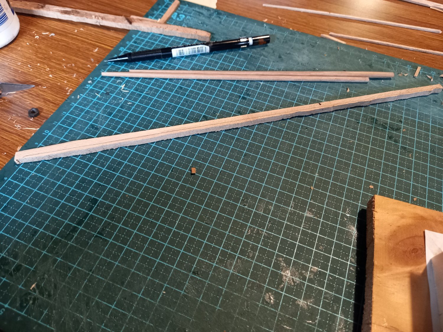
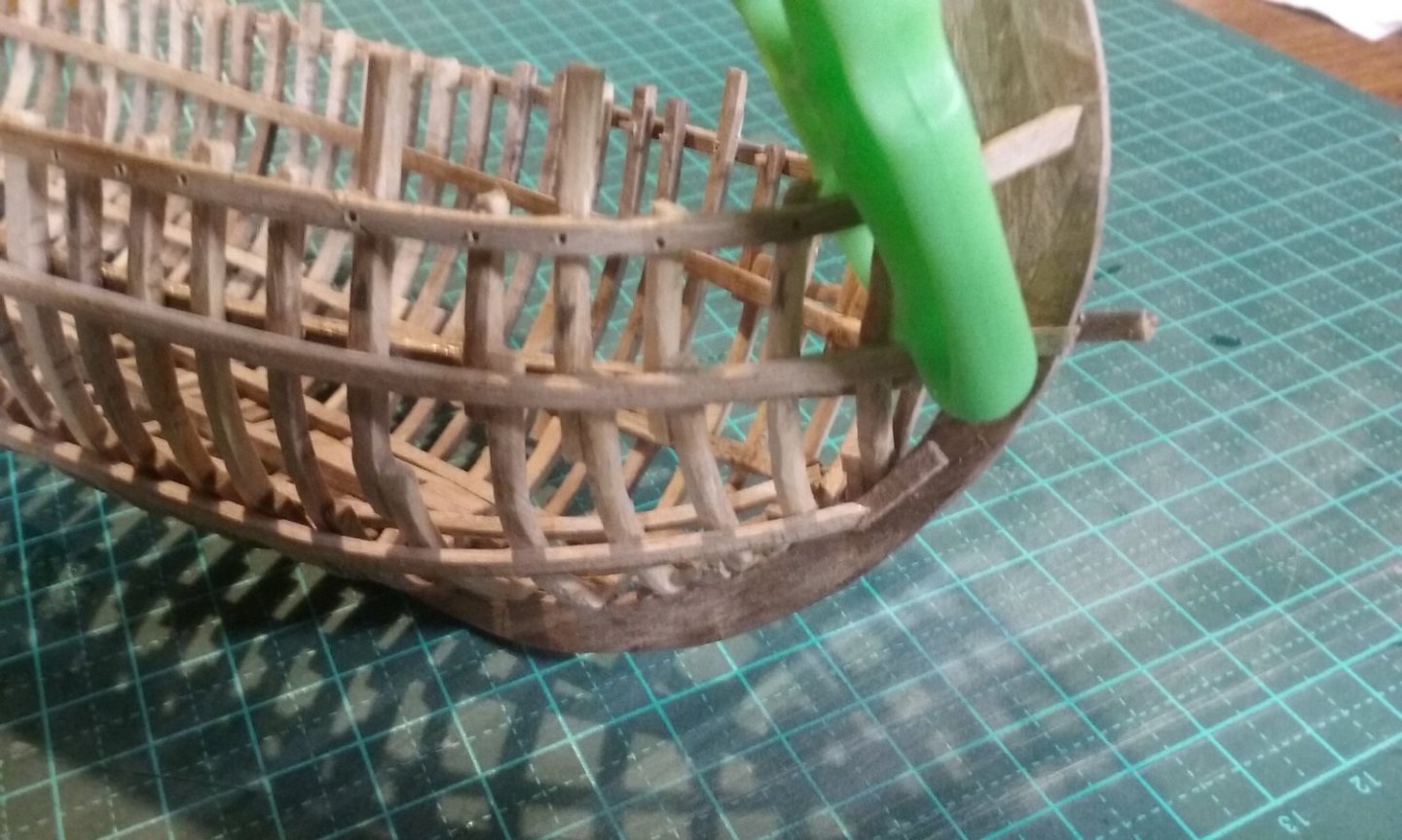
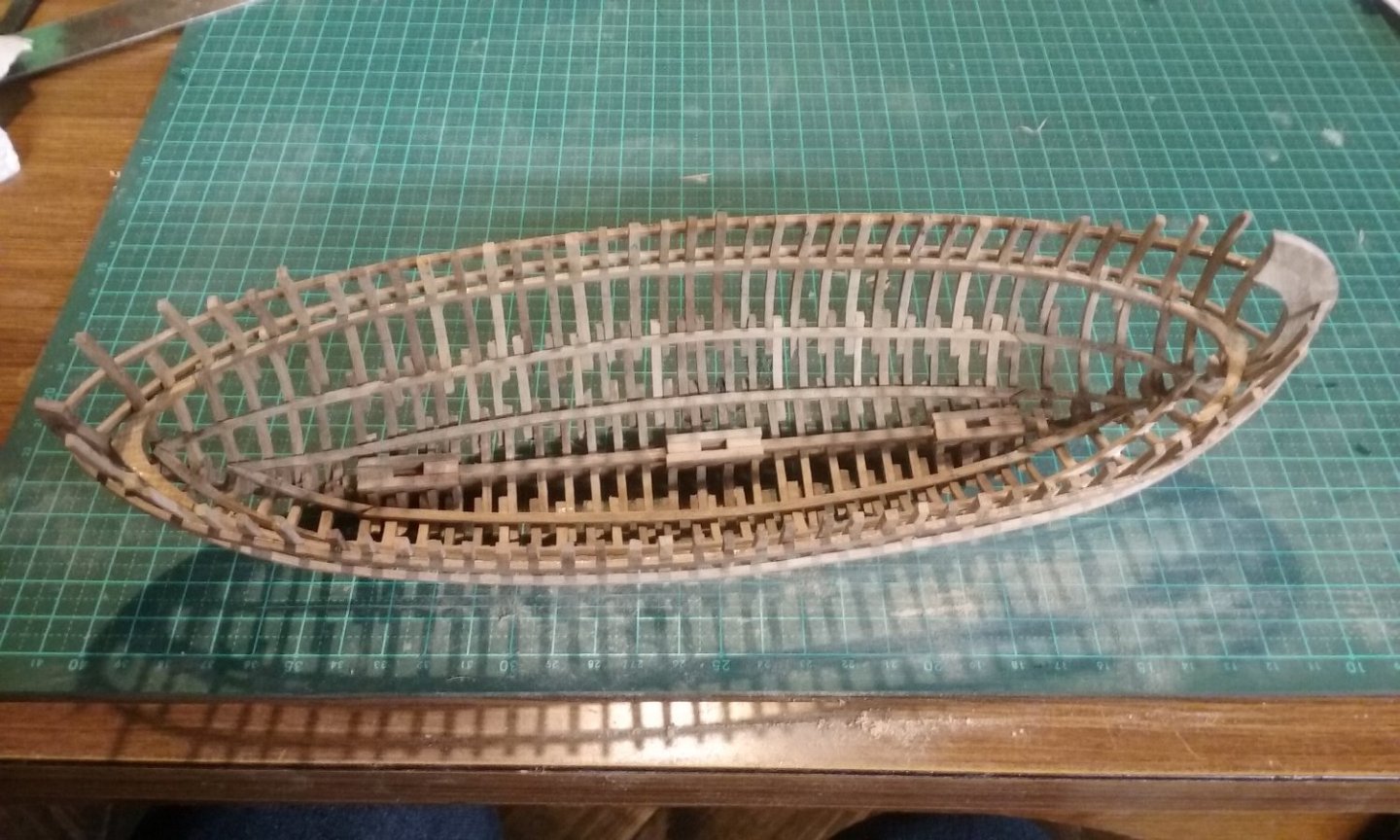
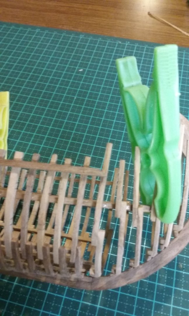
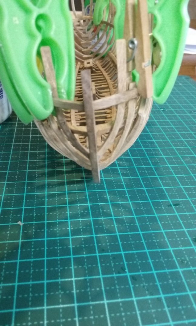
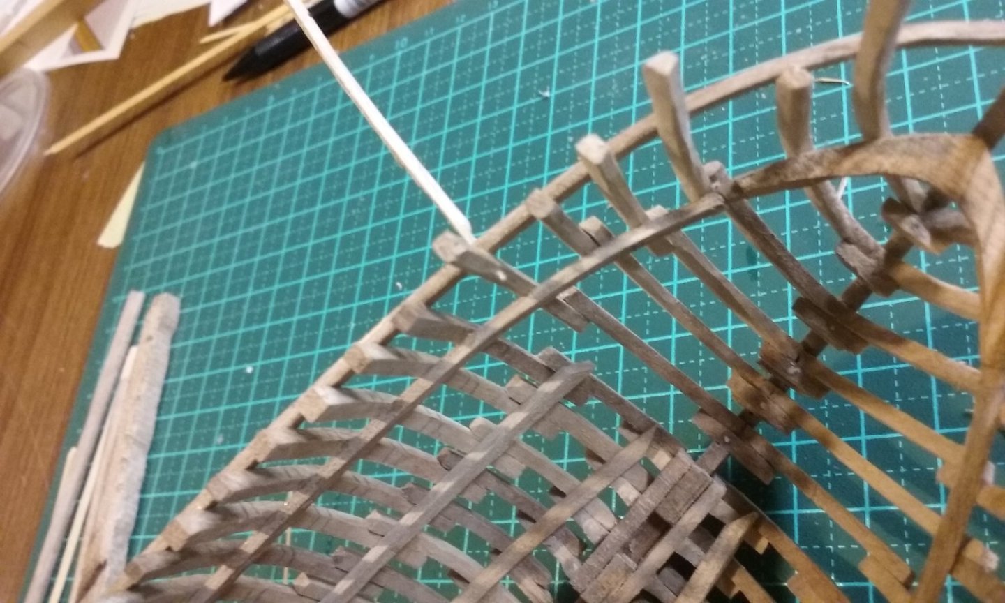
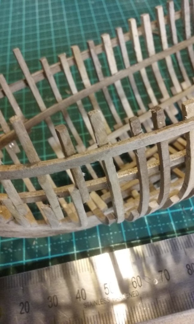
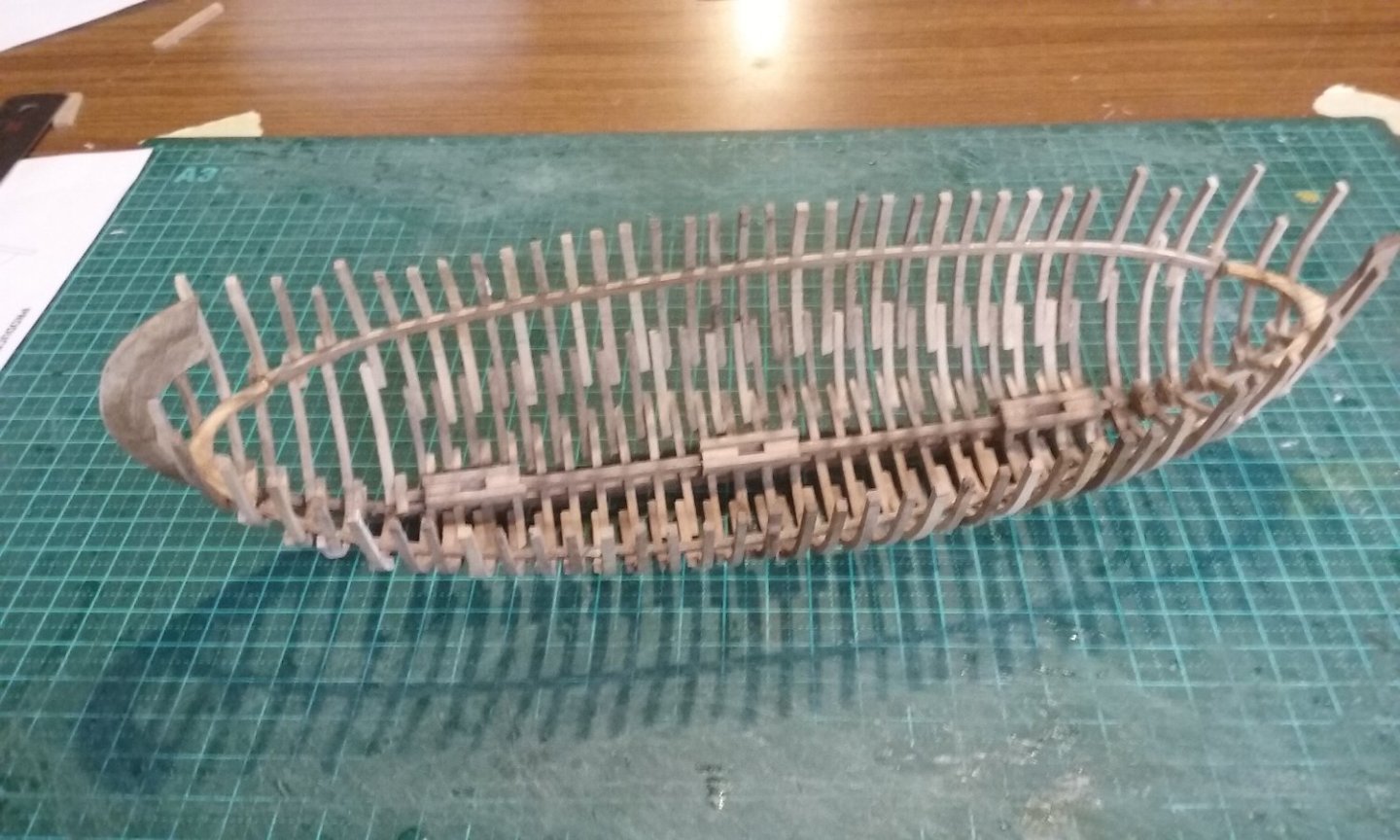
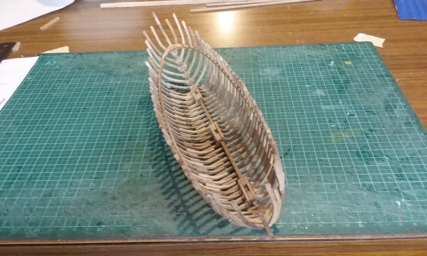
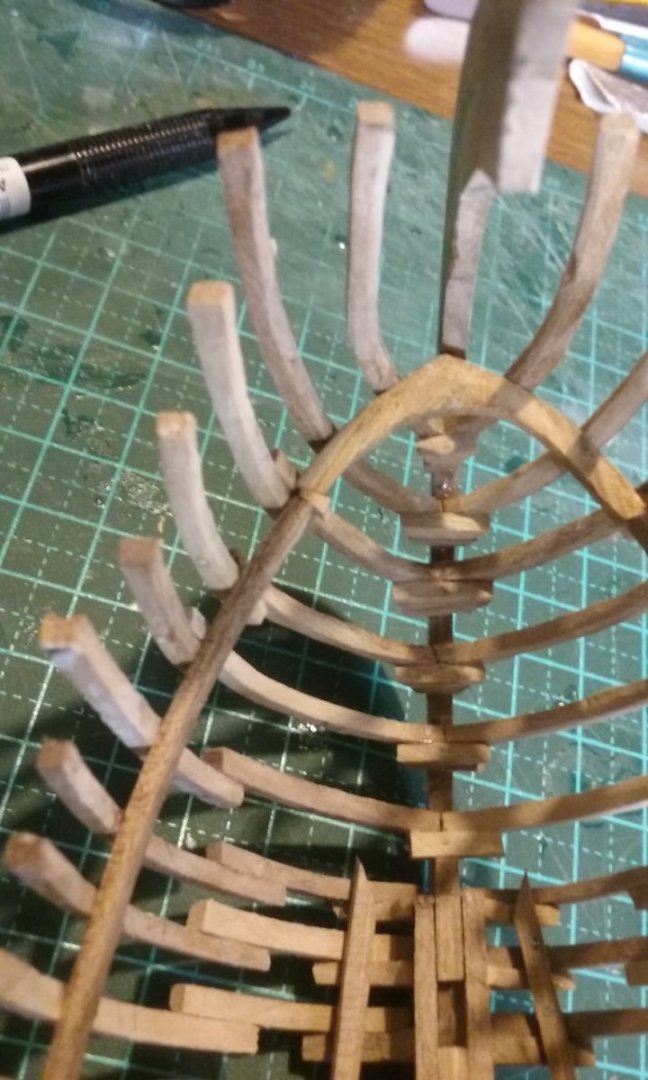
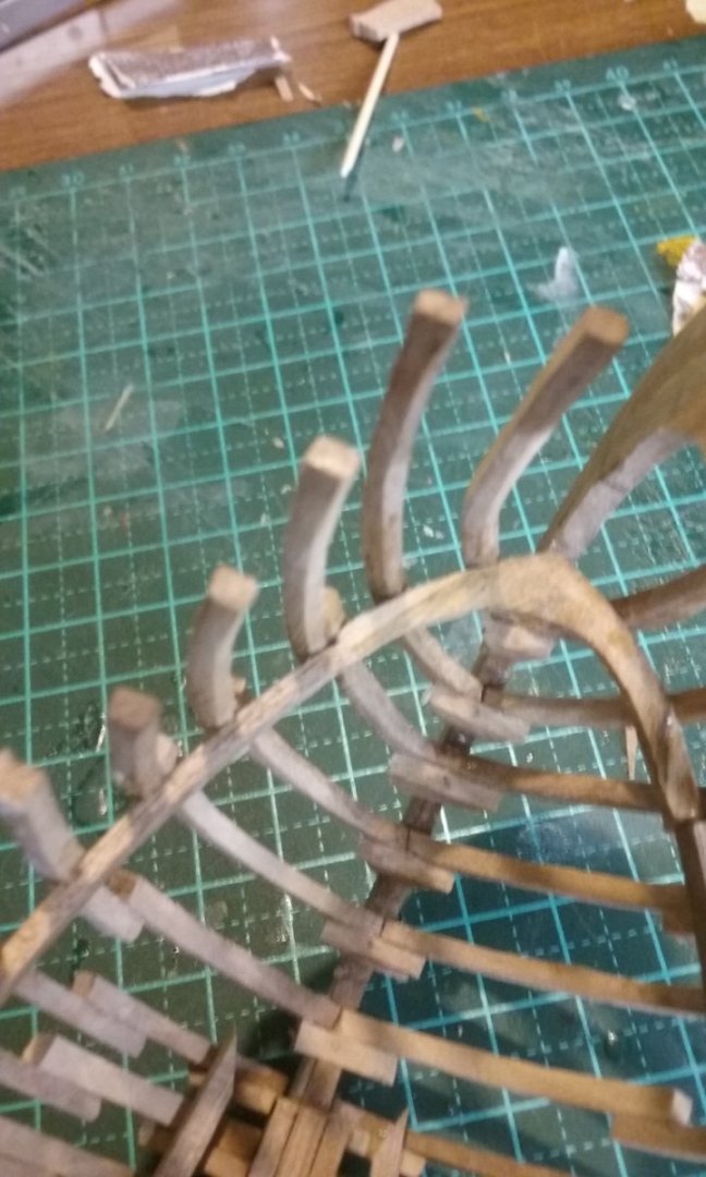
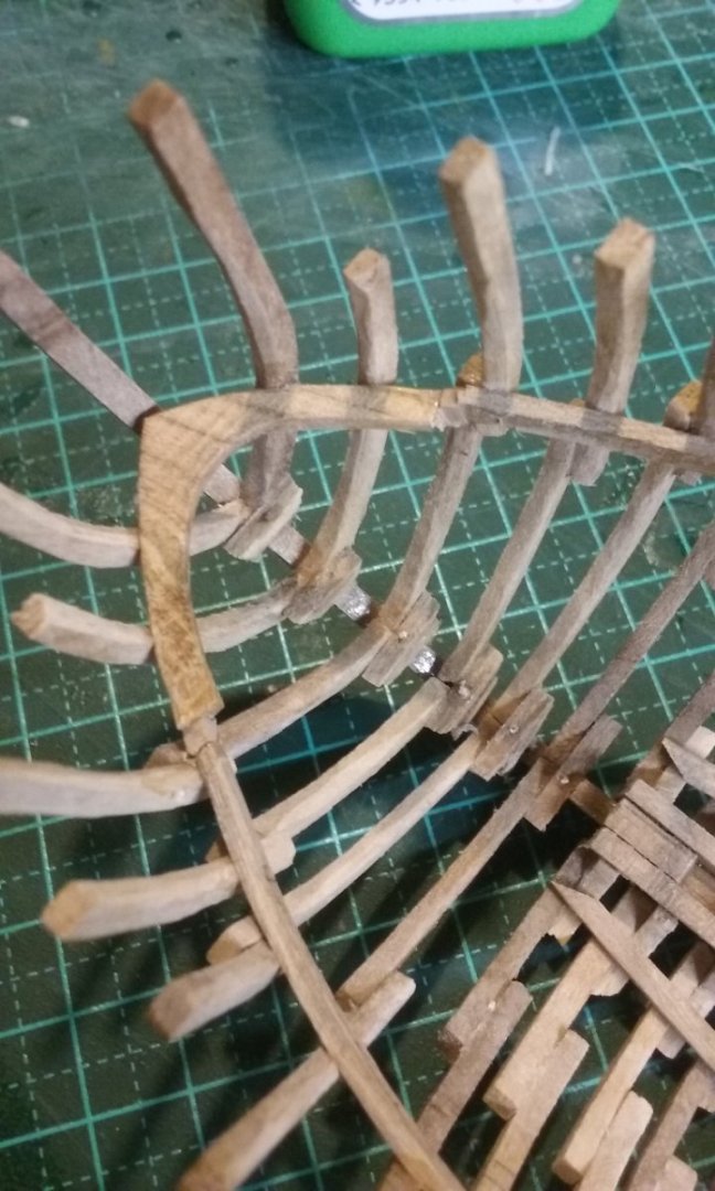
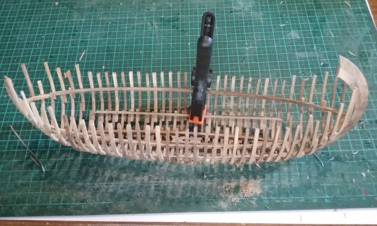
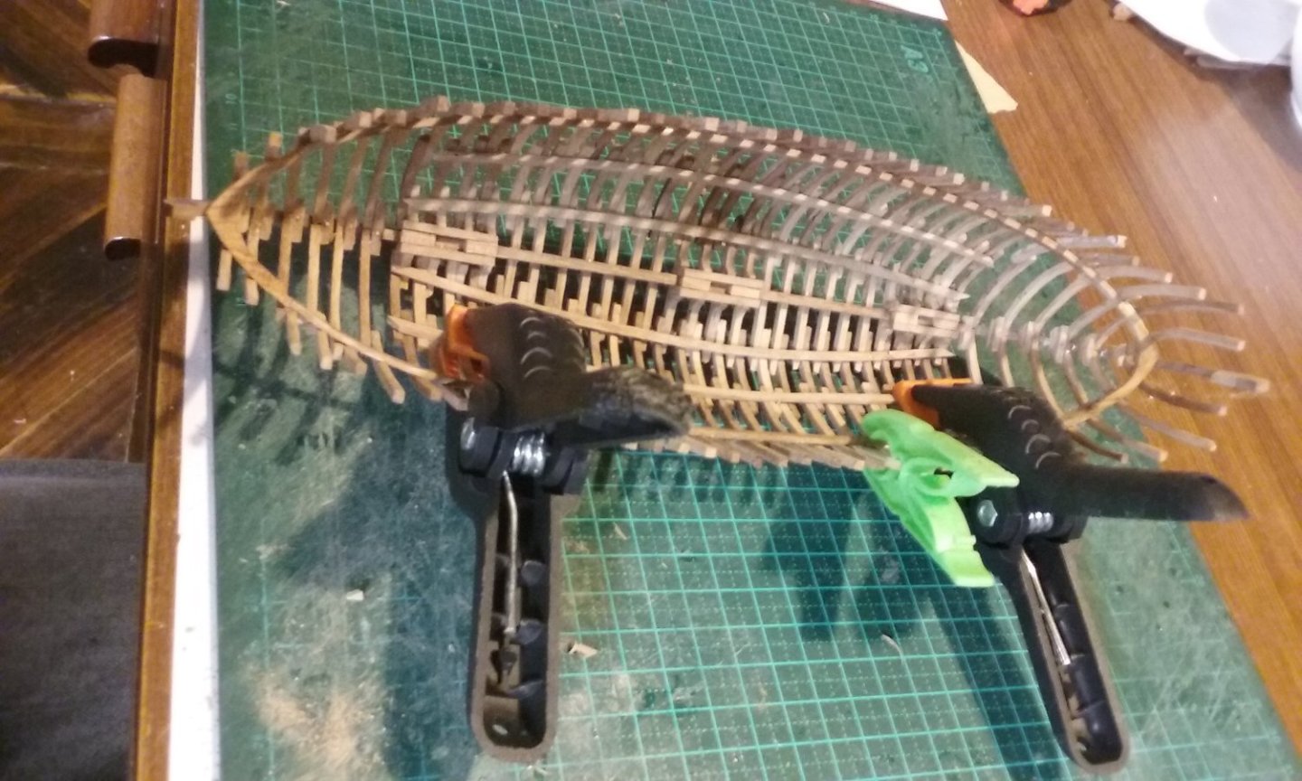
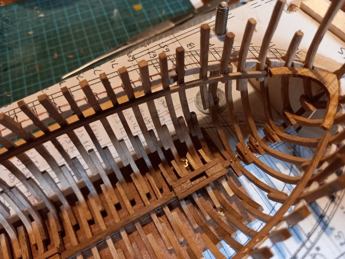
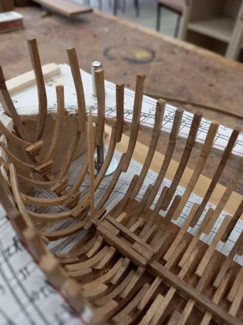
A-a-a-and - the hull is off the jig. I ended up having to pull the jig apart to get the ship out, but worth it. Then I had to do some correction. The pegs are gluing into the correct position some frames that were angled incorrectly (not perpendicular to the keel). Then onto making stringers to make the structure more rigid, and deck beams. Here's my poor man's plank bender (a cheap soldering iron) to get them the right shape. And here are the first bits of deck beam - or are they stringers? I've sort of lost track. (one of them is to be cut up to provide pieces of stringer for the bow or stern, which explains the complex curve). Gluing complete - here she is without the pegs. Adding stringers at the turn of the bilge. There'll be corresponding wales on the outside of the hull, and there'll be strengthening stringers and wales where the second and third futtocks join, and a wale in line with the clamp. The mosaics seem to show a reasonable number of wales, as do the near-contemporary picture from the History of Genoa and the carvings on the Leaning Tower of Pisa. View from the bow. I'd miscalculated the length of the clamps, so they didn't quite reach the breast hooks. Because they didn't meet the rigidity of the hull was lessened, so I glued bits of wood into the gaps to make each assembly effectively a single strong unit. Smoothing off the pieces that fill the gaps. Still some tidying up and smoothing off to do. They won't be visible under the deck, but I'll know if I don't do it right. And the stringers lined up with the join in the futtocks. They will be curved to follow the line of the join. Like this . . . And that's it for today . . . Steven


- 508 replies
-
- 18
-
-

-
Fascinating discussion on why the Vasa really sank.
Louie da fly replied to Louie da fly's topic in Nautical/Naval History
I don't think so. Sounds like another one I have to watch. Steven -
That's a good point, Dick. Definitely food for thought - and considerable pondering. I've just scanned through all my mediaeval pics of lateeners, and only the San Marco and Leaning Tower representations show the top extending forward of the mast - in all the rest (the ones that do have tops), it's behind, except in two which I'm not terribly willing to take as Gospel. Could it be that the mosaic artists and the Pisa sculptors got it wrong? Perish the thought! In the meantime, I've shaped two of the masts and roughed out the other. I was thinking of recycling an unused mast I'd made for the nef but it wasn't quite long enough. I've drilled and pinned the bow and stern frames, glued the clamps in place and added the breasthooks. Steven

- 508 replies
-
- 12
-
-