HOLIDAY DONATION DRIVE - SUPPORT MSW - DO YOUR PART TO KEEP THIS GREAT FORUM GOING! (Only 75 donations so far out of 49,000 members - C'mon guys!)
×


Louie da fly
-
Posts
7,989 -
Joined
-
Last visited
Content Type
Profiles
Forums
Gallery
Events
Everything posted by Louie da fly
-

Oseberg ship burial replicas by Eindride
Louie da fly replied to Eindride's topic in Completed non-ship models
Very nice! I used to do Viking period re-enactment, and those artefacts are pretty amazing. I know what all of them are for except the little cylindrical thing in your hand(though I suppose I could make a guess - for spices, salt, something like that). Steven -
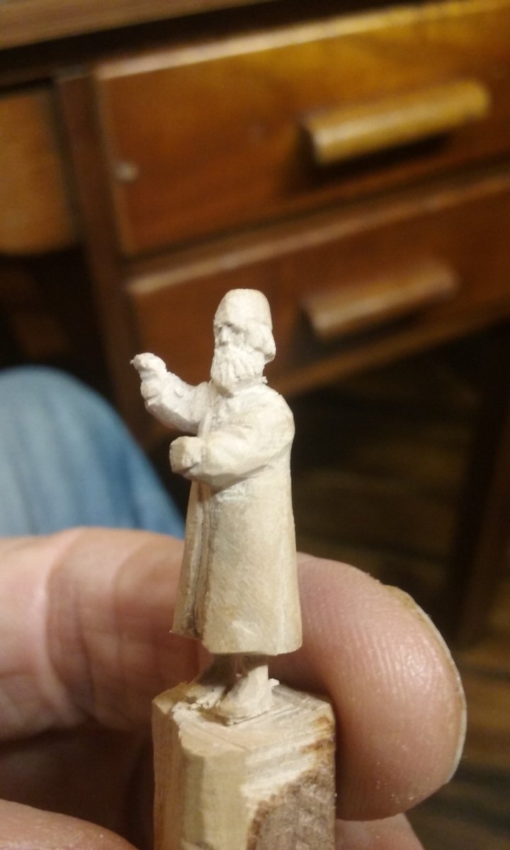
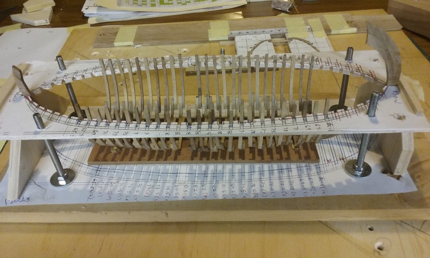
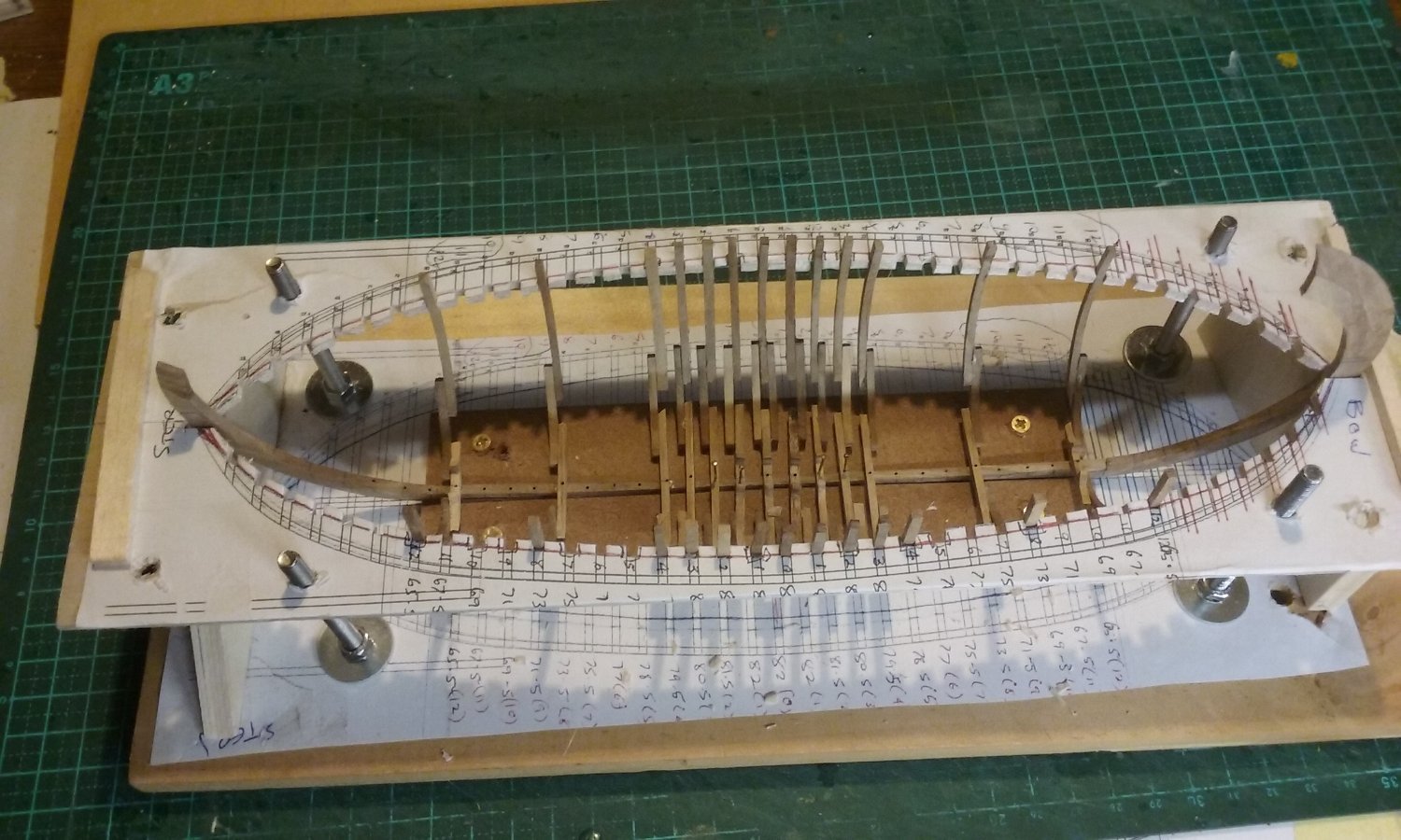
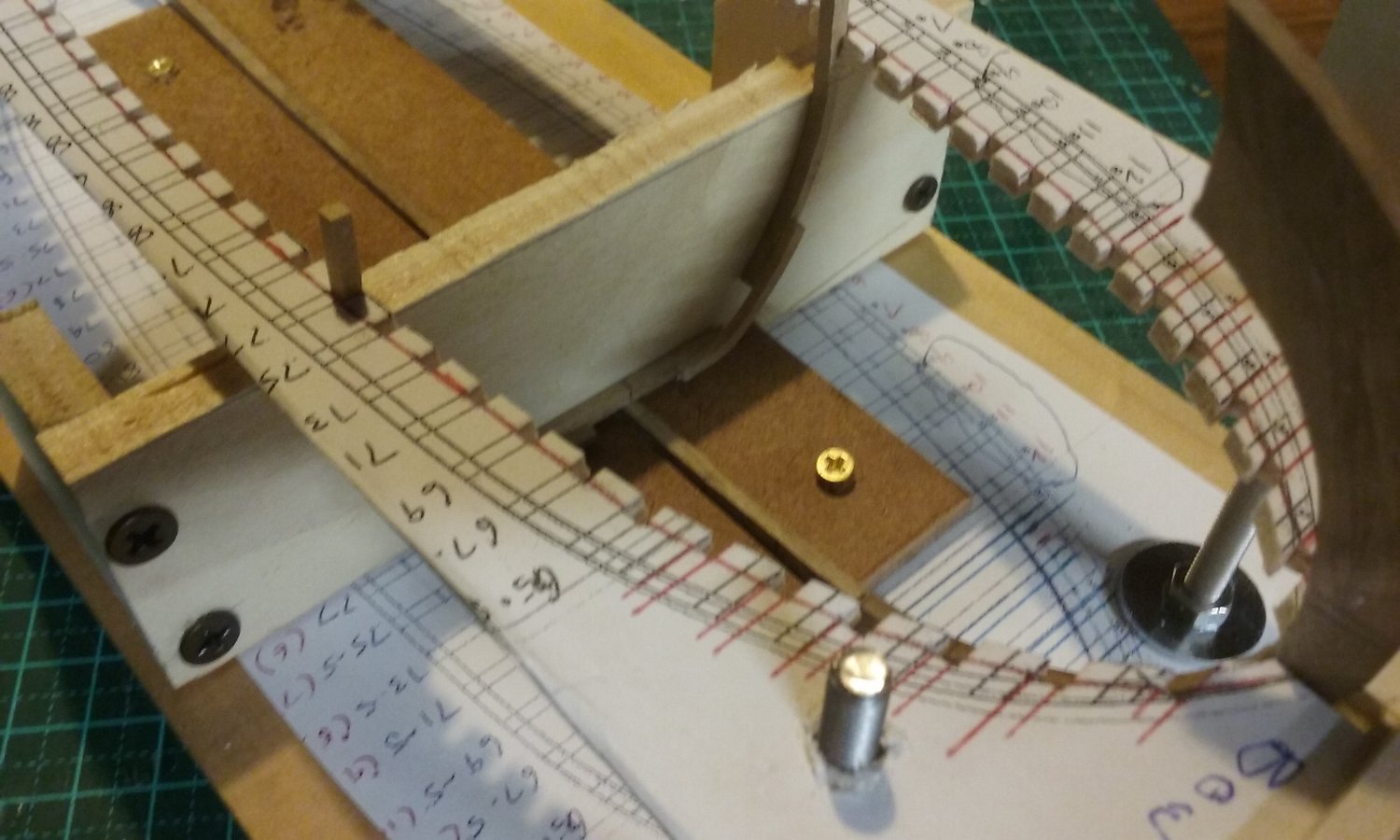
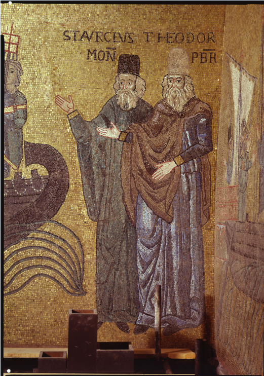
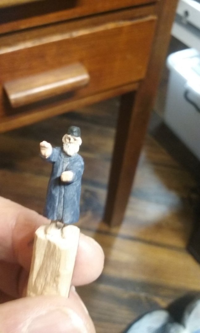
While I was waiting for the rain to go away so I could get power to the shed to drill holes for pins to join the frames to the keel, I thought "Can't sit around forever, waitin - I'll carve one of the merchants who pinched St Mark's body and brought it to Venice, as shown in the mosaic." Here he is (the one on the left) his name is Buono. The other one is called Rustico. Perhaps those names are made up - "Good" and "Farmer" - it is, after all, an apocryphal legend. I'm very happy with the shading of the face. It looks more natural than any I've previously done. Frames dry fitted, to check that they go into the slots in the jig (quite a few of them didn't, so I had to widen the slots). And in the process of gluing them in place And all glued in. The pins are temporary - much too long - the keelson has to go directly over them. I intend to replace them with slivers of bamboo (I have a LOT of bamboo!) cut to length. I may have to drill the holes a bit deeper to make sure of the joint. I'm still working on getting the shape of the end frames correct. I don't want to make a bunch of them and then find I've wasted my time and effort. So the plan is to make a 3D "filler" of bits of plywood (the same thickness as the distance between the frames) laminated together, with paper between layers so I can pull it apart when I've got the shape right and use them as templates. Fortunately the bow and stern frames will be identical. Steven


- 508 replies
-
- 11
-

-

-
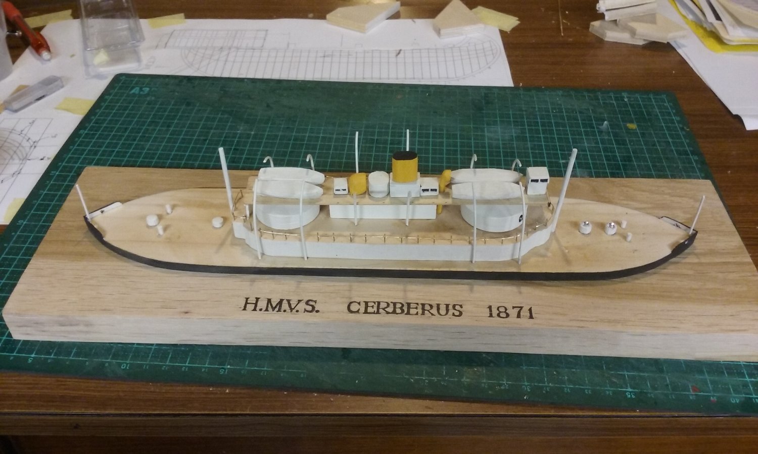
Well, you could have knocked me over with a feather. I come into the Men's Shed this morning and one of the guys says "Oh we sold your model of the Cerberus". It'd only been up for sale for about 3 days (in with the wooden cutting boards and bird houses etc), in the room where everybody's projects are up for sale. It's in a community building which used to be a high school and we work in the wood workshop with all those wonderful tools available to us. A guy came in with a bunch of schoolkids, saw the Cerberus up for $100 and bought it! Amazed. I'm still not going to make another of the Cerberus - too fiddly for the amount of effort I want to put in, and I'm really not proud of the quality of the model, but it shows there is a market out there for such things. But there are other projects that I am interested in, simpler to do, but just as likely to produce a sale. I'm not in it for the money, but it's nice to be able to get something back for the group, and in return for the effort. Maybe there's a new career out there for me (I'm on the pension, so the money really isn't important, but I'm allowed to make a fair bit from hobbies before it affects the pension, and a bit of pin-money would be nice). Steven
-
As I mentioned before, you're doing very good work. Keep it up! Steven
- 18 replies
-
- 1
-
-
- Amati
- Chinese Pirate Junk
- (and 2 more)
-
Bienvenu, Alain. Welcome to Model Ship World! Steven
-
You might like to check out previous builds of this wonderful boat - see https://modelshipworld.com/search/?q=african queen&quick=1 Steven
- 57 replies
-
- 6
-
-
- live steam
- radio
- (and 2 more)
-
Beautiful work, Glen. You're doing a wonderful job, particularly at such a small scale. And I thought 1:200 was difficult! Steven
- 290 replies
-
- 6
-
-

-
- Quinquereme
- Finished
- (and 1 more)
-
Very nice work, Bob. Those ships were so beautiful. I like the planking, and the clever addition of fake "framing". Nice precise detail work. Keep up the good work, but be kind to yourself and give yourself a chance to recover properly. Steven
-
I've only just come across this build. You've done a very nice job. It's hard to believe this is your first ship model. A couple of tips for next time. Planking; you've done a nice job, but in the real world planking is done differently, to avoid sharp corners at the ends (which don't hold nails or treenails). There are some very good planking tutorials which explain exactly how to do it for next time. This one is particularly good. The only other point I feel could be made is regarding the rigging. The ropes running through the blocks, and the ones holding the sail battens to the masts, look rather too thick for the size of vessel. There was a gradation of rope thicknesses depending on the forces they were to be subjected to. So halyards (the ropes that haul up the sails - they haul the yards) are pretty thick because they have to take a lot of weight, but where you have light loads, or several ropes sharing a load, the ropes can be thinner. Also, though the ropes that hold up the masts (known as standing rigging) are usually tarred to preserve them, so they are dark brown or almost black, any rope used to control the sails (i.e. they usually run through blocks) would not be, as the tar would clog up the blocks. So they'd be a natural light colour - pale brown or even white. Having said that, these comments are intended as a heads-up for your next model, so you're forewarned and can incorporate that information into your next build. It's all part of the learning experience. Don't even think of changing the current one. You've done a very good job, particularly for someone new to the field. Looking forward to your next build. Steven
- 18 replies
-
- 4
-
-
- Amati
- Chinese Pirate Junk
- (and 2 more)
-
Looking good, Patrick! Steven
-
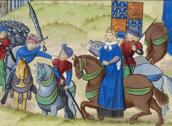
My post was written with my tongue very much in my cheek. The fact that Edward III had already previously paid homage to the "usurping" French king rather tends to invalidate his - and every other English monarch's - later claim to the throne of France, doesn't it? Well, you know what happened to THEM, don't you? Death of Wat Tyler, leader of the Peasants' Revolt during a "negotiation" with King Richard II. https://www.wattylercountrypark.org.uk/peasants#:~:text=Kent rebels led by Wat,He died an agonising death. Steven
- 45 replies
-
- 2
-
-
- Great Henry
- Henry Grace a Dieu
- (and 1 more)
-
I finally got around to doing a video of the Dromon. Strangely it turned out to be better filming it in artificial light (just the normal overhead fluoros in the room) than using natural light. Clearer, better colour and far fewer reflections fom the transparent surface of the case. Steven 20230703_194350.mp4
-
TENUOUS???? Zounds, sirrah, them's fighting words! (Check the first scene of Shakespeare's Henry V to find the basis of the claim. Complex but fascinating - the French dismissed the claim of the king's daughter on the basis that she was a woman and "No woman shall succeed in Salic Land" - see https://blogs.loc.gov/law/2012/04/happy-birthday-william-shakespeare-henry-v-and-salic-law/ ) Steven
- 45 replies
-
- 1
-
-
- Great Henry
- Henry Grace a Dieu
- (and 1 more)
-
HMCSS Victoria 1855 by BANYAN - 1:72
Louie da fly replied to BANYAN's topic in - Build logs for subjects built 1851 - 1900
Nice to hear. I only just got interested in that part of things. Interestingly, the Cerberus must have flown the current flag of the State of Victoria - at least until Federation in 1901 - as it was gazetted within a couple of years of the ship arriving here. Steven
- 1,013 replies
-
- 7
-
-
- gun dispatch vessel
- victoria
- (and 2 more)
-
Well, the jigs worked - sort of. It then comes down to "how accurately can I centre this tiny drill in this almost as tiny floor timber?" So, we'll see how it all goes. Unfortunately, the handle of the drill press (you know, the three-armed thing with knobs on that you rotate to get the drill to descend) knocked the stempost off the keel as it came down. DAMN! Fortunately, no actual breakage, just have to glue it back together again But it means I've got those pinholes drilled to pin together the frames and keel, except for the ones on the stempost (obviously!) and the sternpost, where I couldn't drill vertically into a curving timber without the drill bit bending to follow the curve. After a couple of attempts I gave up. No photos unfortunately. Didn't think of it. Steven
-
Thanks, but I won't celebrate till I've made sure they actually work - otherwise I'mm being a bit previous. I certainly hope so Steven
-
No real need, but thanks. There's plenty on-line, even down to diagrams of the lines. I'll be oversimplifying this one, too, and I haven't even decided yet whether it'll be a full hull or just a waterline model (a lot easier, but not as attractive). Steven
-
HMCSS Victoria 1855 by BANYAN - 1:72
Louie da fly replied to BANYAN's topic in - Build logs for subjects built 1851 - 1900
While researching flags for the Cerberus, I came across this article which outlines two flags used for Victoria's navy prior to 1870, and probably flown on the HMCSS Victoria. Thought you might be interested. https://prov.vic.gov.au/explore-collection/provenance-journal/provenance-2012/crown-and-kangaroo-victorian-flags Steven- 1,013 replies
-
- 6
-
-
- gun dispatch vessel
- victoria
- (and 2 more)
-
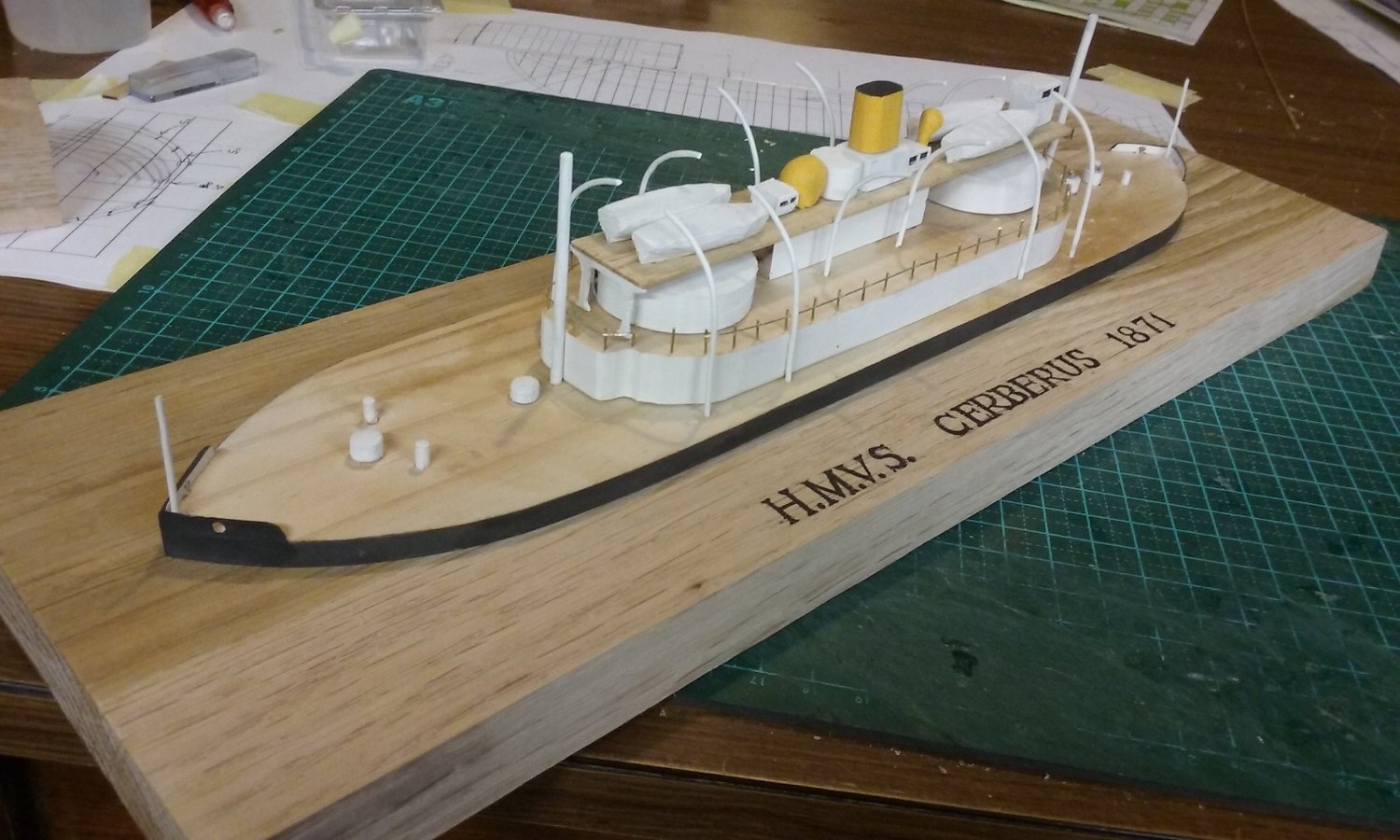
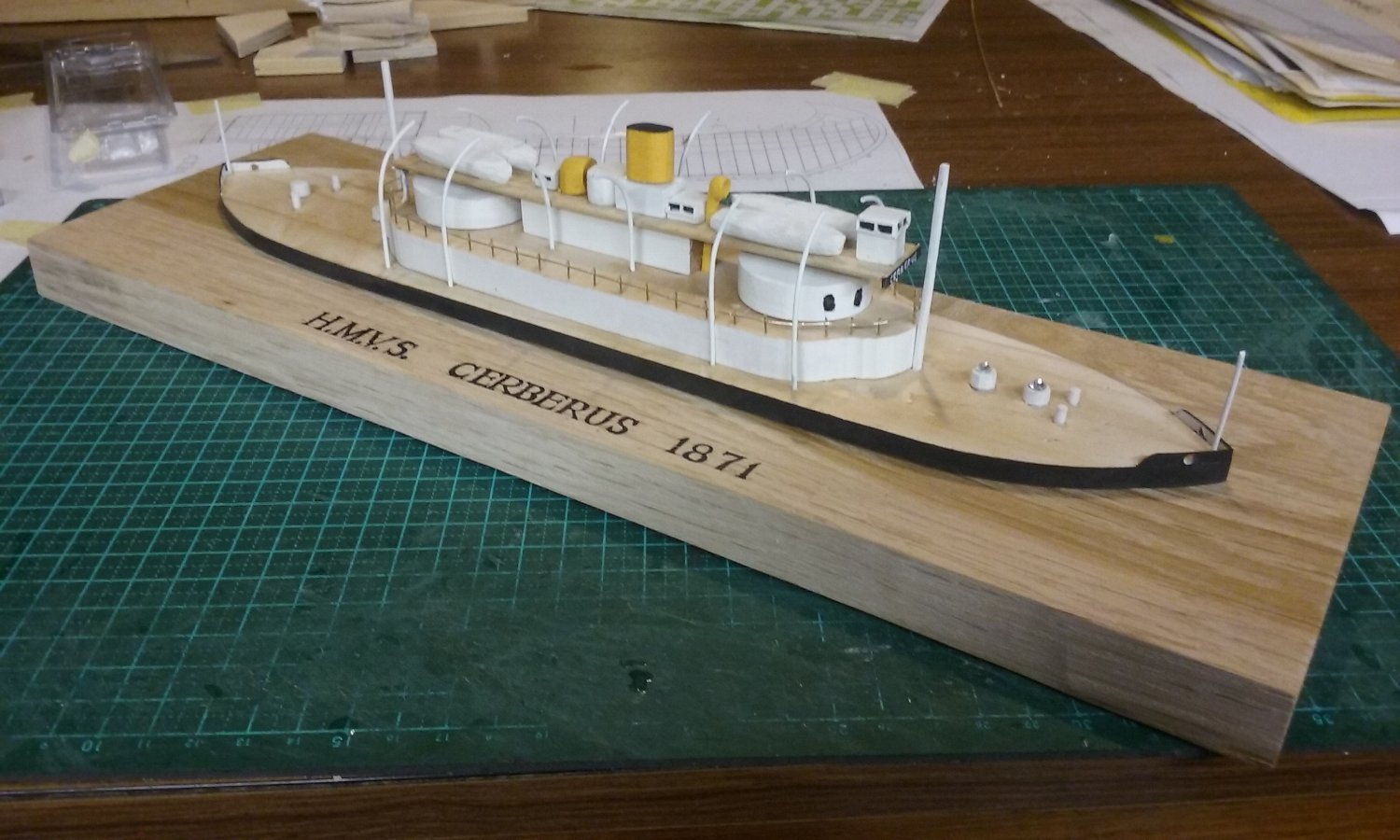
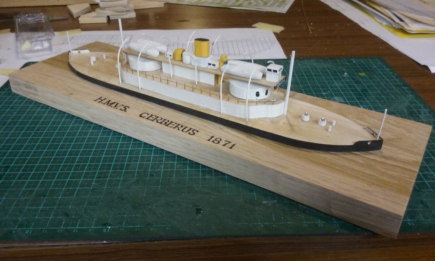
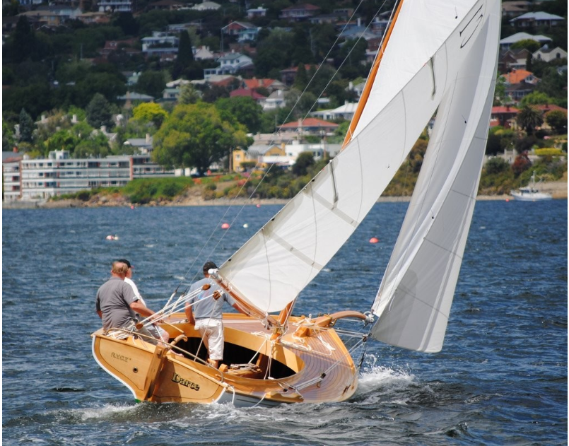
Well, the experiment is complete. I wanted to know if I could mass-produce a simplified version of the Cerberus as a fund-raiser for the local Men's Shed. Simple answer - no. It appeared fairly uncomplicated at first glance, but as I progressed through the build I came up against a dilemma - either I had to oversimplify it to the degree that it would not look interesting enough to be saleable, or I had to add all the details that made it look interesting and make it uneconomical as a project. Add to that the fact that I was always faced with the choice between doing it fast enough to be worthwhile (= fairly careless) and my own pride in my work. As it turned out, it was neither fish nor fowl nor good red herring - not precisely enough built to satisfy me, and too fiddly and slow to mass-produce. It's ok, I suppose, but I can't see myself doing it again. If I'd wanted to do a proper model of the Cerberus I'd need to put a lot more time and effort into getting it right, just to be satisfied with it. I'd want it to be a model I was proud of, and I'm really not prepared to do that at the moment, if ever. I have too many other projects I'd like to get into. So as an experiment it was a success - I did want to find out whether or not it was suitable for its original purpose, and the answer is no. As a model I'm less than satisfied with it. I'll still put it up for sale - somebody will probably love it, but I won't put a terribly high price on it - it's not well enough made and finished to justify it. My next experiment will be making a couta boat (originally for catching barracuda in the years up to the 1920s and 30s when they were superseded by motorboats), a particular favourite in the State of Victoria, where a lot of them have been preserved and are used for racing. Steven


-
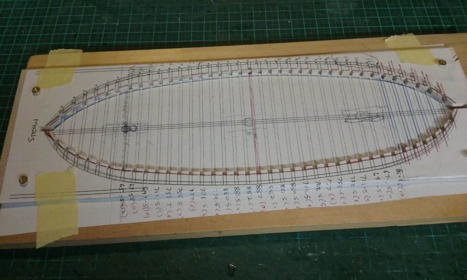
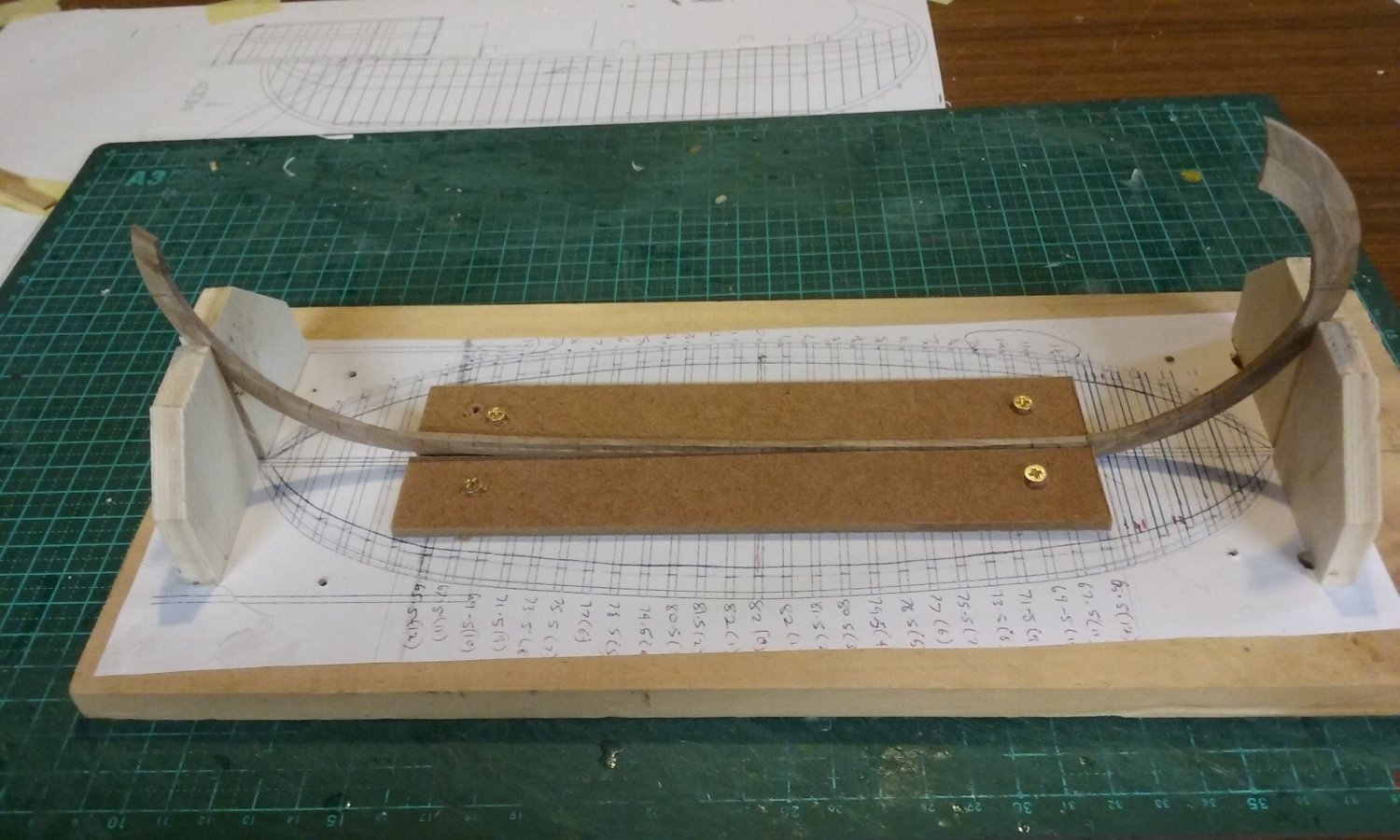
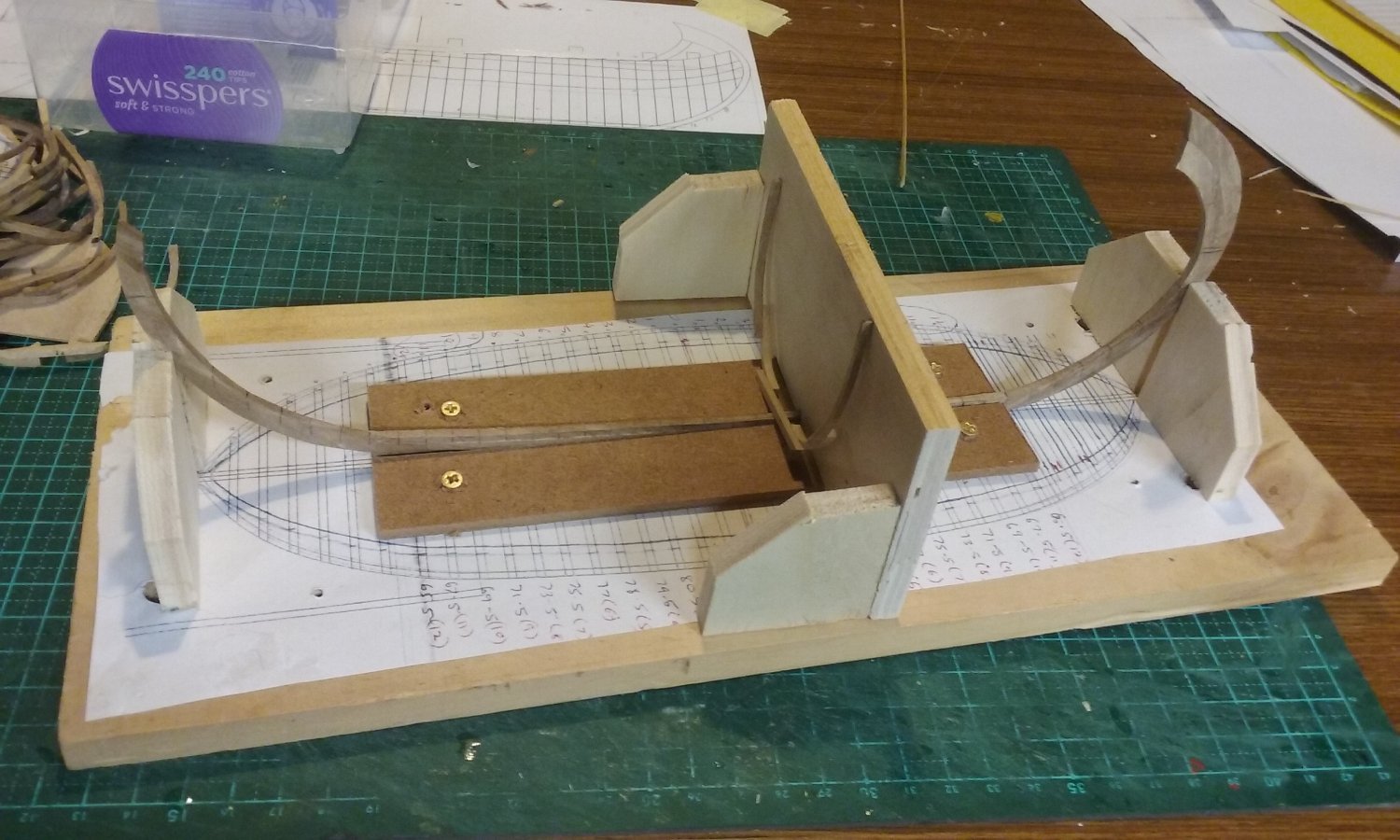
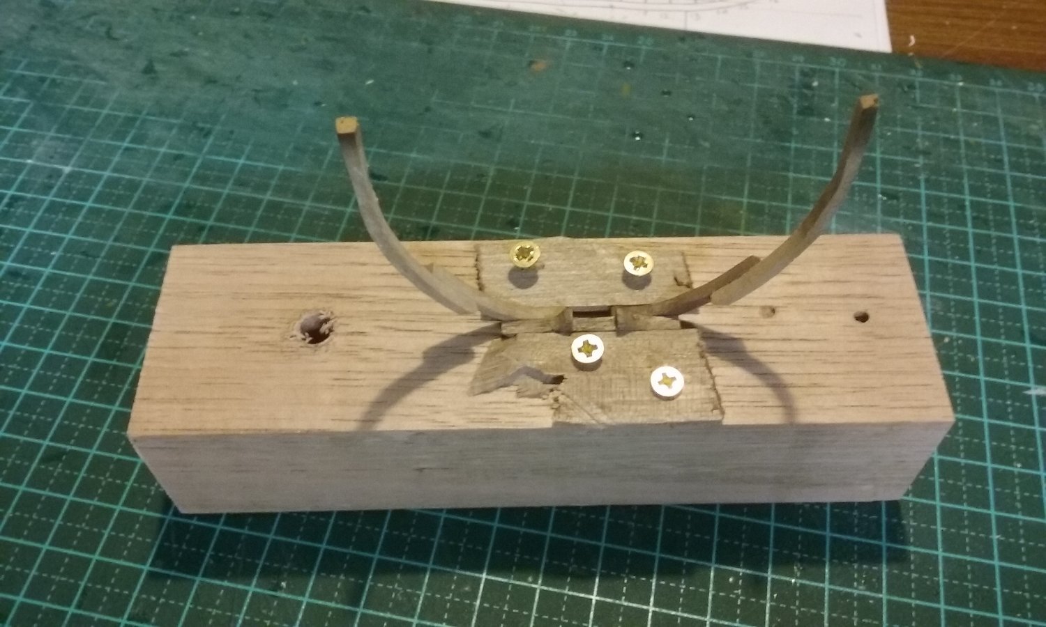
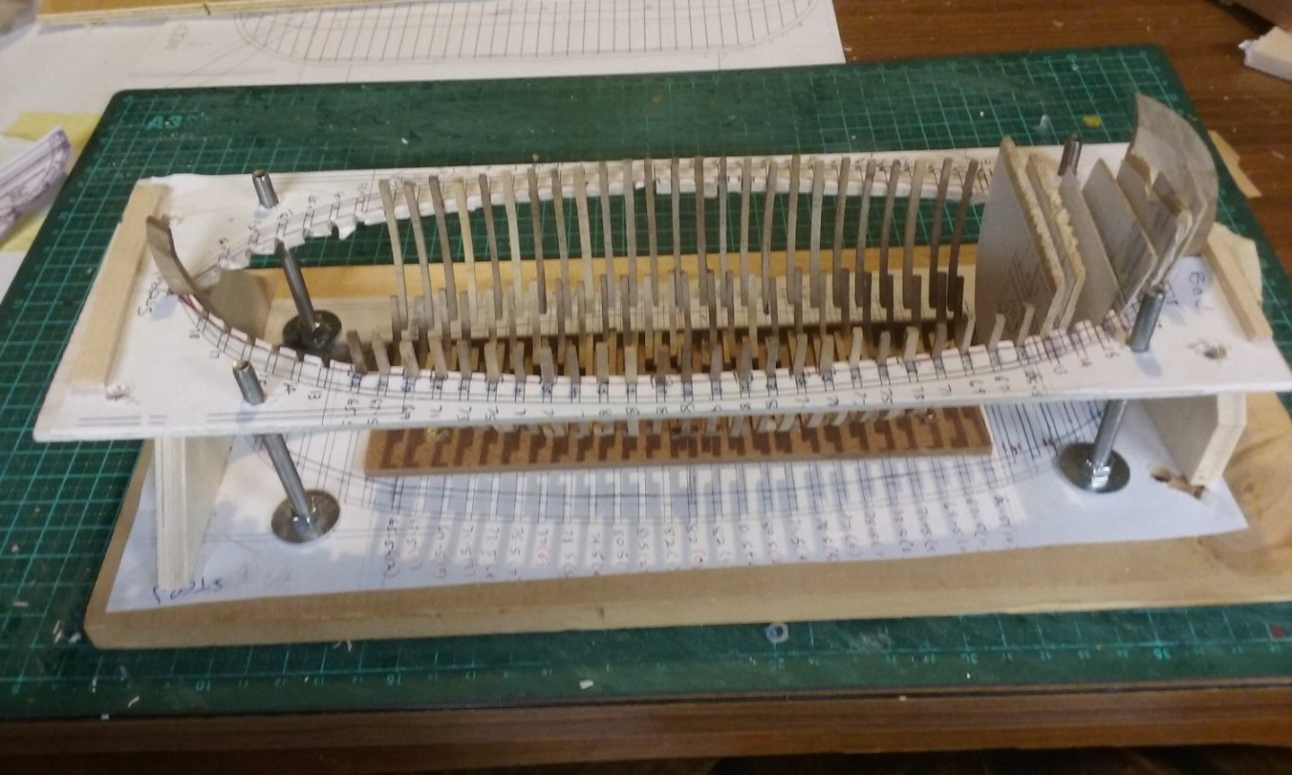
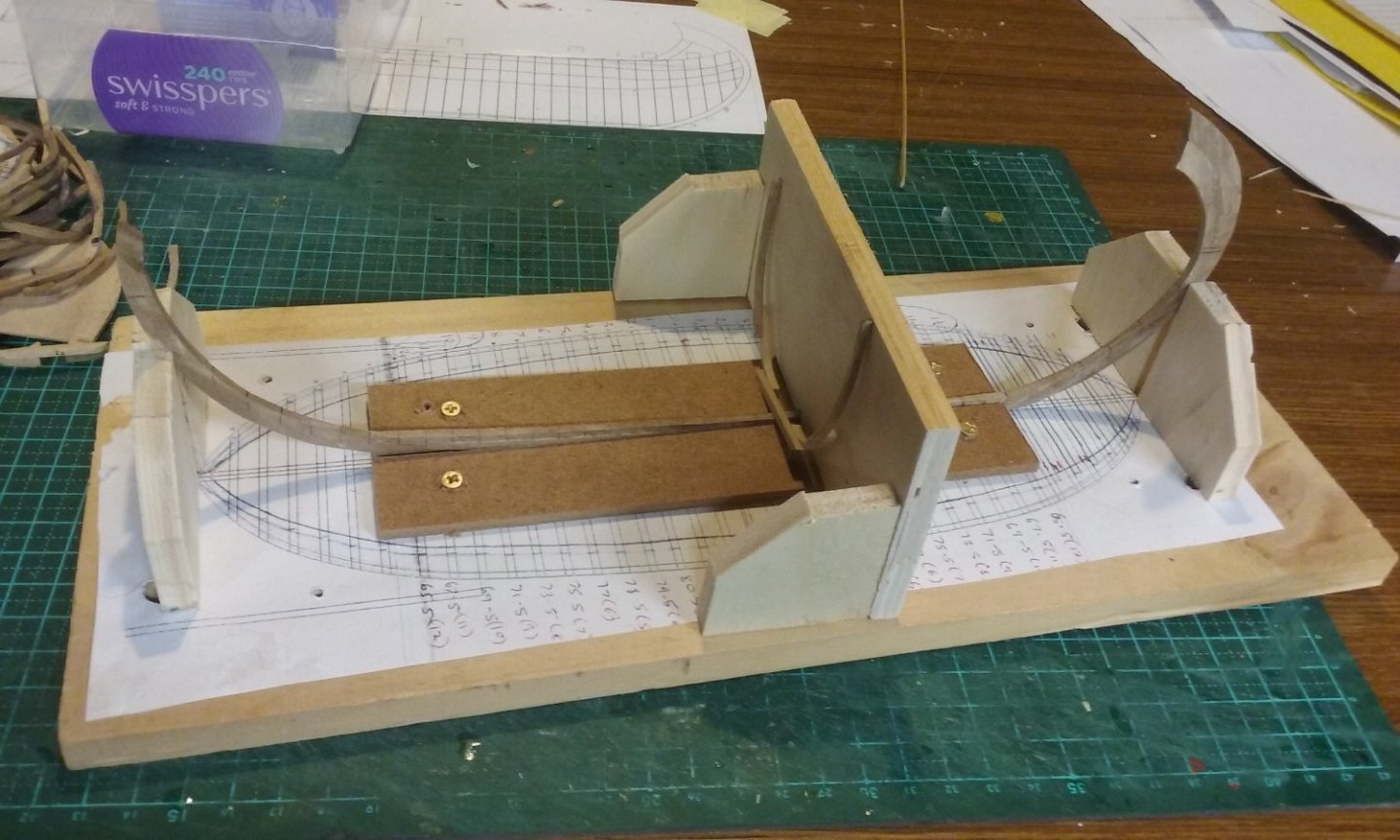
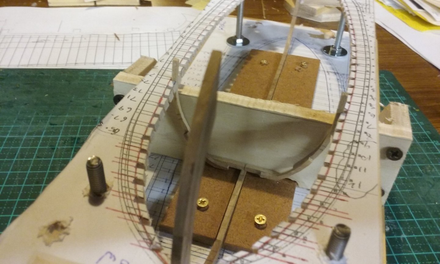
I've been working on jigs of various types to enable me to do the framing and keep it straight and square. There's been a bit of experimentation involved, some of which I cancelled because I'd found a better way, others because I hadn't thought far enough ahead and had to undo things because they got in the way of other things. First, emulating Woodrat's 14th century round ship build, I made a cut-out template of the hull shape with slots for the ends of the frames, superimposed over a base to take the keel and the bottoms of the frames. Aren't photocopiers wonderful! Those scrawled figures are the overall widths of the frames, worked out by the mezza luna method (thanks, Woodrat!) And here's how I intended to support the keel - version 1. The thin masonite strips ('packers' as used in the building trade) have nice vertical sides and are thin enough to let the keel stick out above them a little. The truncated triangles at the ends are right-angled, to keep the stem and sternposts exactly vertical. And a piece to slide along the keel (it has cut-outs at the bottom to fit over the keel and the masonite packers) to ensure the frames are vertical and at right angles to the keel. A jig to keep the frames vertical while I drill holes for pins to hold them to the keel (they'll be both pinned and glued). This is different from Woodrat's method, as I'll (hopefully - see below) be using a drill press to make sure the drill bit is vertical. I used bits of scrap wood but they have nice vertical edges. The upper template held above the lower with long bolts. The sliding jig had to be cut down shorter to pass between the upper and lower templates. A lot of mucking around in this procedure - on the first bolts I bought the thread didn't go all the way along the shank - something I hadn't noticed when I bought them. So I had to go and get new ones that did. But there weren't enough nuts with the bolts - I'll have to go and get some more to screw the tops of the bolts down on top of the upper template. I also found the triangles I'd made to keep the stem and sternposts vertical GOT IN THE WAY, so I removed them and discovered that the bolts were doing the job very nicely, so they weren't needed after all. Now I have to wait for the rain to go away. My shed has a drill press but no power (can't fit it in the budget at the moment) so I have to string a power cord from the house to the shed if I want to use power tools. And electricity and water aren't a very good combination. In between times, I've pencil-marked the locations of the wales and the deck beams on each frame, as well as the location of the proposed holes for the pins to hold them to the keel. I've also pencil-marked the locations of the frames on the keel itself, so I can do the corresponding holes for the pins. There's quite a bit of drilling to be done before I can move on to the next step, but it's nice feeling I'm making progress, however slow. Steven


- 508 replies
-
- 14
-
-
-
Well, you're getting there despite the trials and tribulations (what doesn't kill us makes us strong). Fortunately wood is a forgiving medium, and if all else fails, you can remove the faulty piece and make it again, as you've done here. And now it's really starting to take shape and look like an actual ship. Keep up the good work. Steven
-
One of his servants was the Groom of the Stool (look it up!). Apparently a very desirable appointment as it meant you had the King's ear (well, something of the King's, anyway). Steven
- 45 replies
-
- 2
-
-

-
- Great Henry
- Henry Grace a Dieu
- (and 1 more)