DONATION DRIVE - SUPPORT MSW - DO YOUR PART TO KEEP THIS GREAT FORUM GOING! (91 donations so far out of 49,000 members - C'mon guys!)
×


Louie da fly
-
Posts
7,989 -
Joined
-
Last visited
Content Type
Profiles
Forums
Gallery
Events
Everything posted by Louie da fly
-
 Looking good. I'm glad your bending technique is working for you. I started out that way but I kept getting burnt fingers from holding the wood in the path of the hot air - now I use a different method - I soak the piece of wood and then bend it over the barrel of a cheap soldering iron. You can get very good results that way (and don't burn your fingers - unless you happen to touch the soldering iron by mistake). BTW I don't know if they're available in the UK but in Oz you can get tiny clothes pegs from craft shops. I even managed to luck upon a set of plastic ones (much less chance of the peg sticking to the frame). Oh, and you asked for help with terminology - what the general public calls "ribs" are technically known as frames. Not sure about the correct name for the bench rails - are they the timbers that support the ends of the seats (known as thwarts, by the way, though in a large oared vessel such as a galley they are known as benches. No idea why the difference.) Anyway, this is coming along very nicely. Keep up the good work. And I liked your "save" for the frame that didn't line up with the others. Steven
- 24 replies
-
- 3
-

-
- Ships boat
- Ships of Pavel Nikitin
- (and 1 more)
-
Nice work on the reef points and bolt ropes. Regarding Vikings using reef points -there's no proof either way; the earliest pictorial evidence I've seen for reef points is from the seal of the English town of Hastings from the 13th century. There's a fuller discussion in Woodrat's "Elusive Hulc" build log (post # 165 onwards) - well worth a look. However, Viking picture stones show a fascinating array of ropes attached to sails - the current theory is apparently that they were used to try to keep the homespun wool sails from stretching - https://www.researchgate.net/figure/Type-C-D-Viking-Age-stone-from-Hejnum-Riddare-The-clearest-example-that-the-dragon_fig5_287096117 Not suggesting you try to emulate this, but what a fascinating subject for speculation. As far as I know nobody's yet tried to model a ship with this rigging. I'd be fascinated to see somebody do it. Steven
-
Thanks for the suggestion, but the main thing is that in future builds I keep in mind the effect of the wales' location on the planking so I don't make the same mistake again. Too late for this model - there's no way I'd be prepared to undo all I've done and start again. This is a "for future reference" issue. Steven
-
Am I right in thinking you gave a talk on ship modelling to the assembled multitudes? (I've been trying to get some of the Ballarat modellers over to the Dark Side. So far not a sausage). Steven
-
Did you meet Leigh from Ballarat's modelling club? He went along. Didn't come along to our next meeting - some story about feeling tired and emotional after the modelling exhibition. Steven
-
Welcome to MSW, Derek! You might like to have a look at this site to work out what vessel you'd be best starting off with. But definitely start with something simple, learn the skills that are specific to ship modelling (particularly wooden ship modelling!), and work up to something more complex as you gain confidence. And when you begin your build, you should also start a build log. If it's a kit, go to https://modelshipworld.com/forum/130-build-logs-for-ship-model-kits-by-era-launch-date/ and choose your time-period, then follow the instructions here to begin the log: A build log is a great way to get help and advice from people who've been doing this for years. In my experience the membership here are very helpful and friendly. And have fun with it! That's the whole point of doing this stuff. Steven
-
A nice solution, mate! Looks very good. Your research on this build is very impressive, too. Steven
-
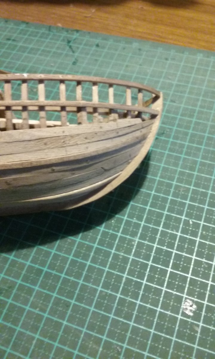
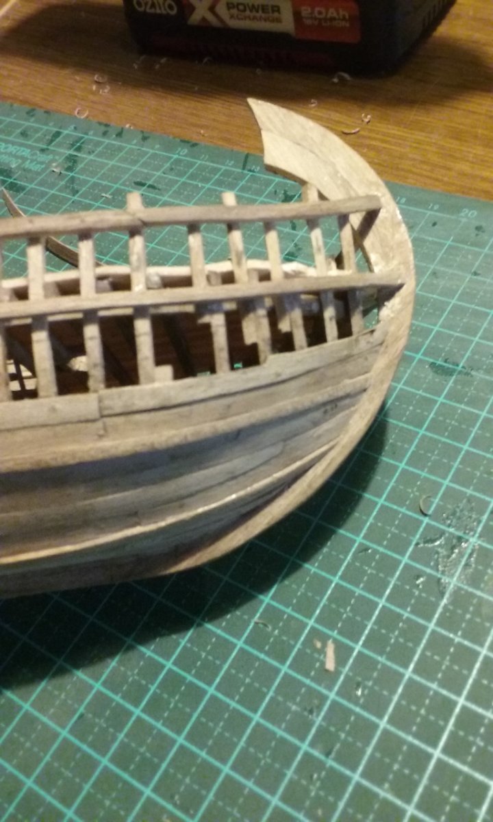
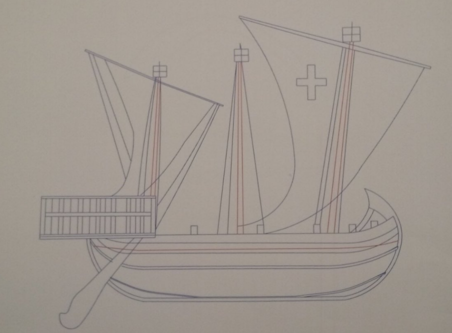
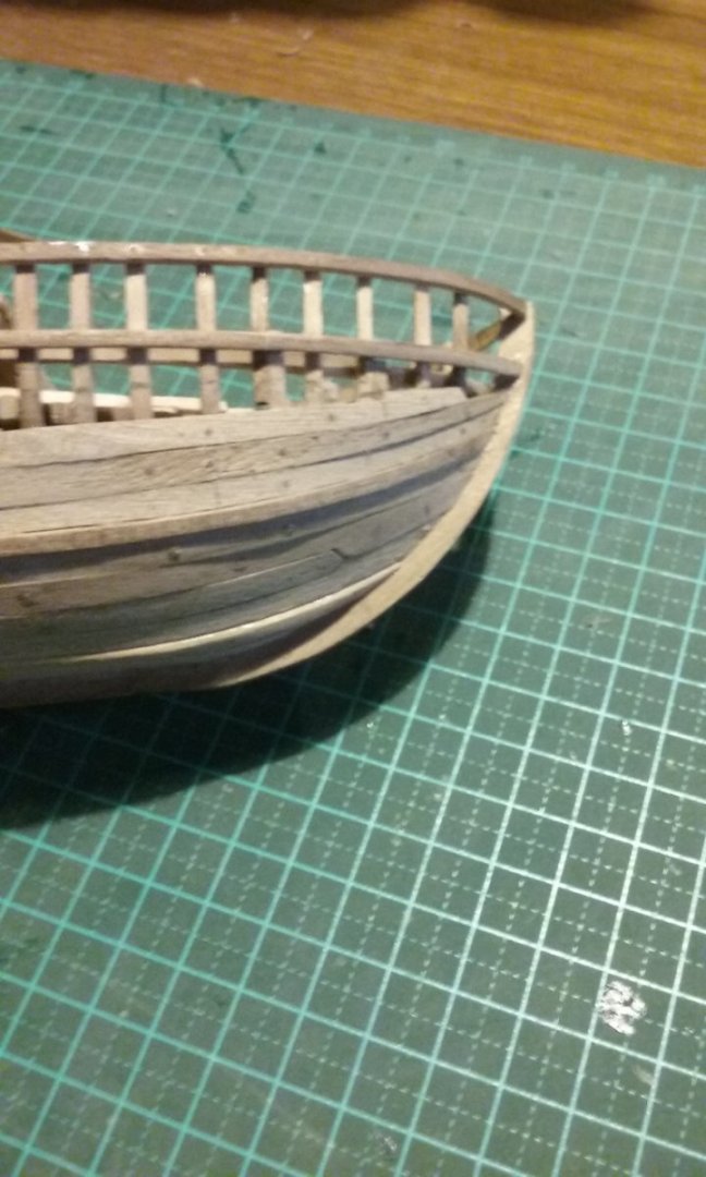
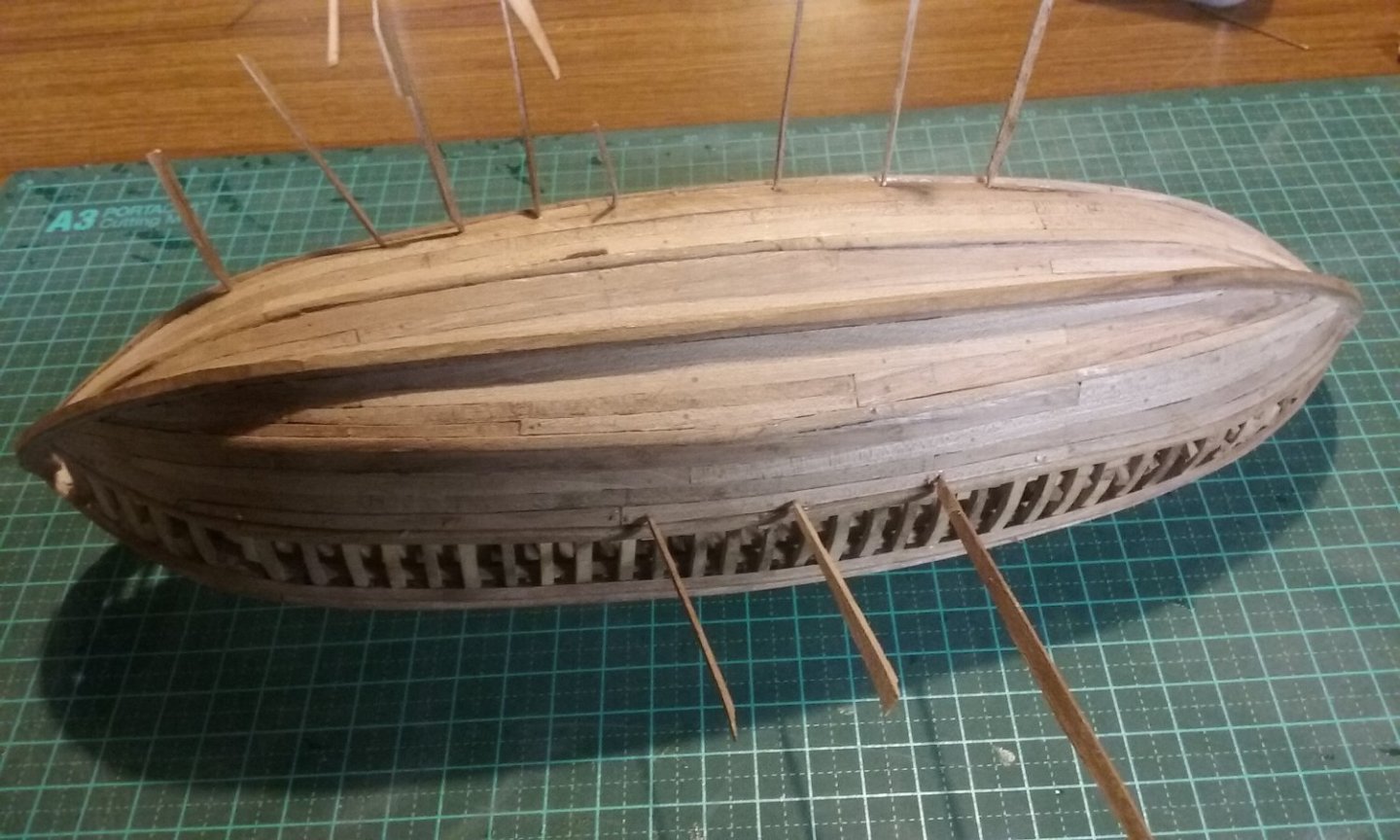
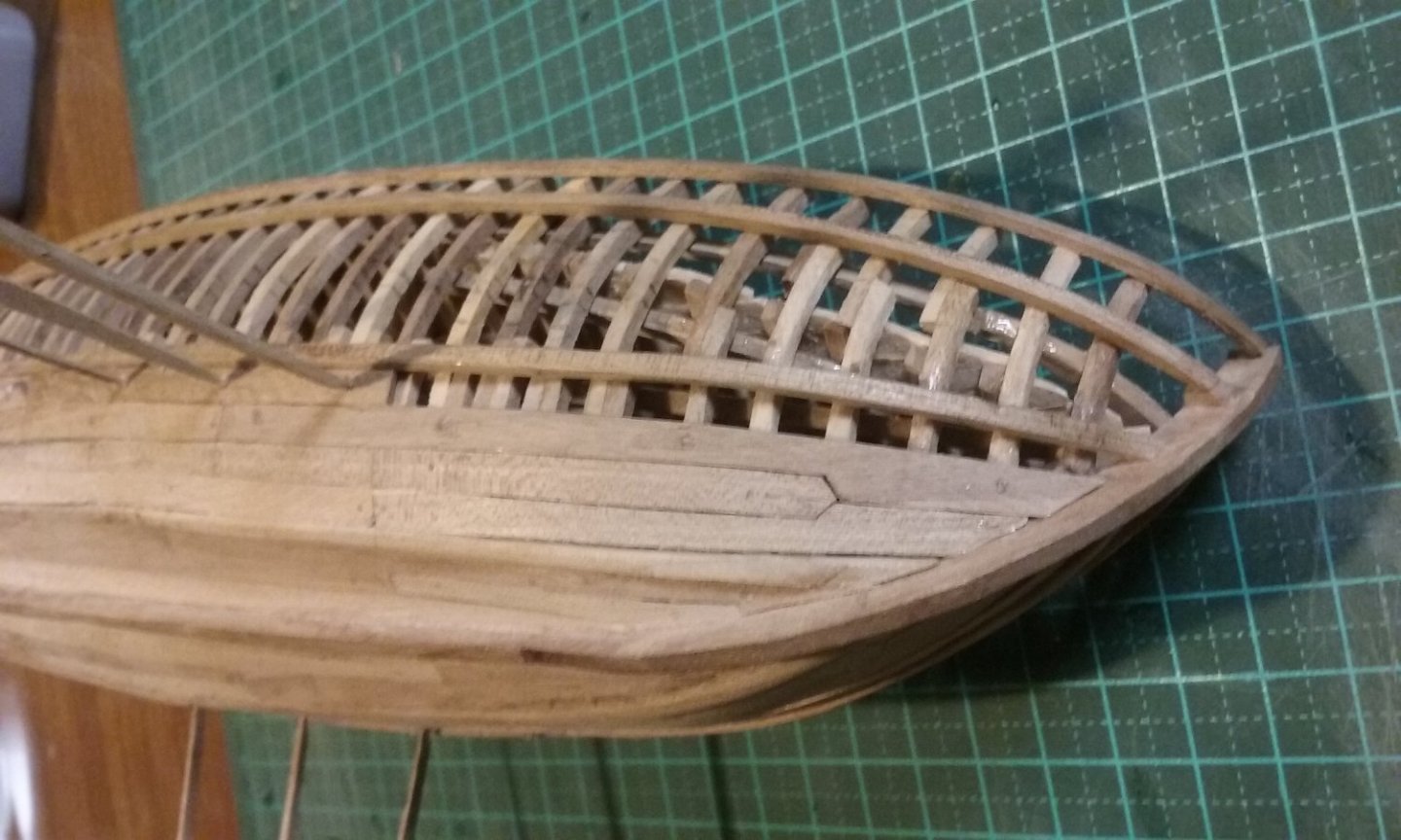
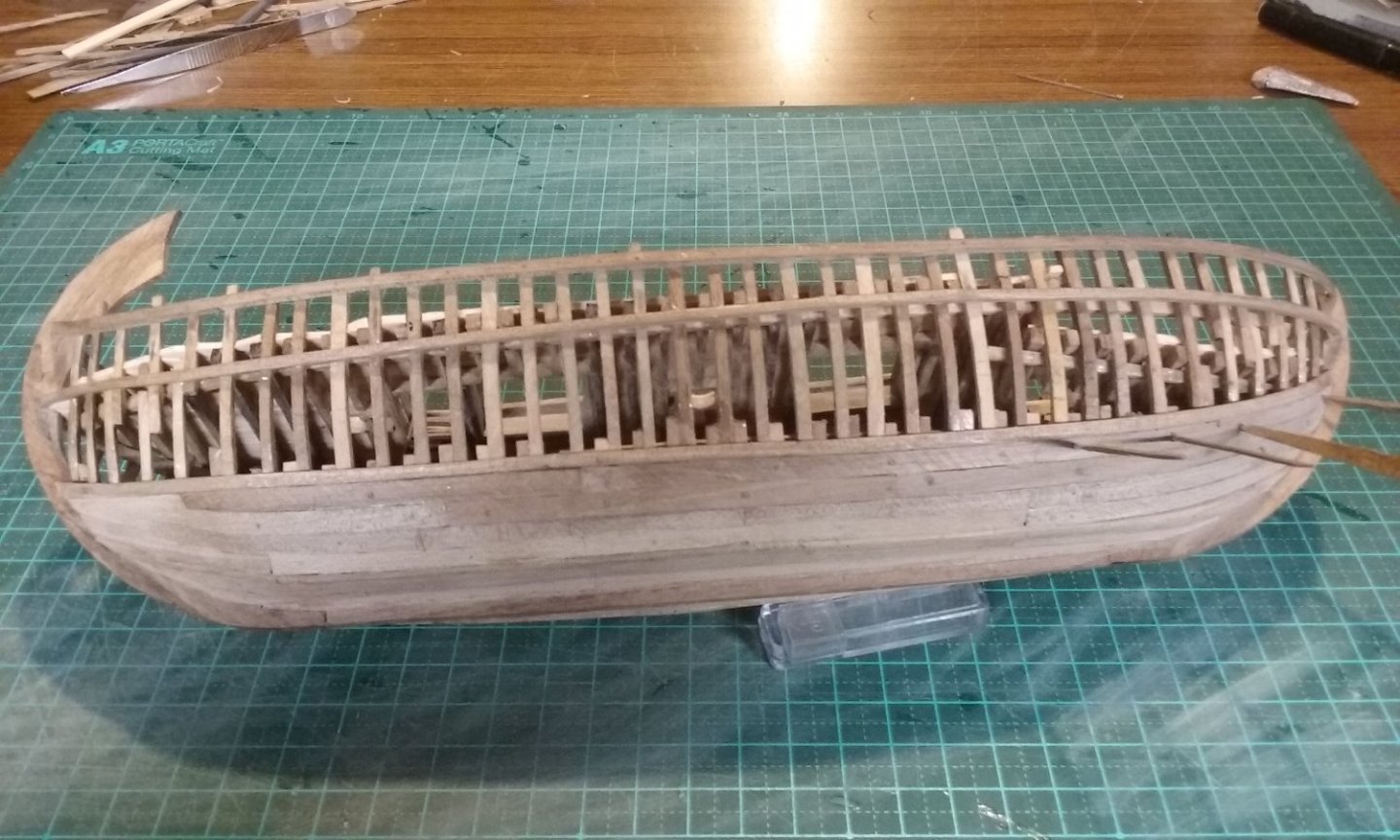
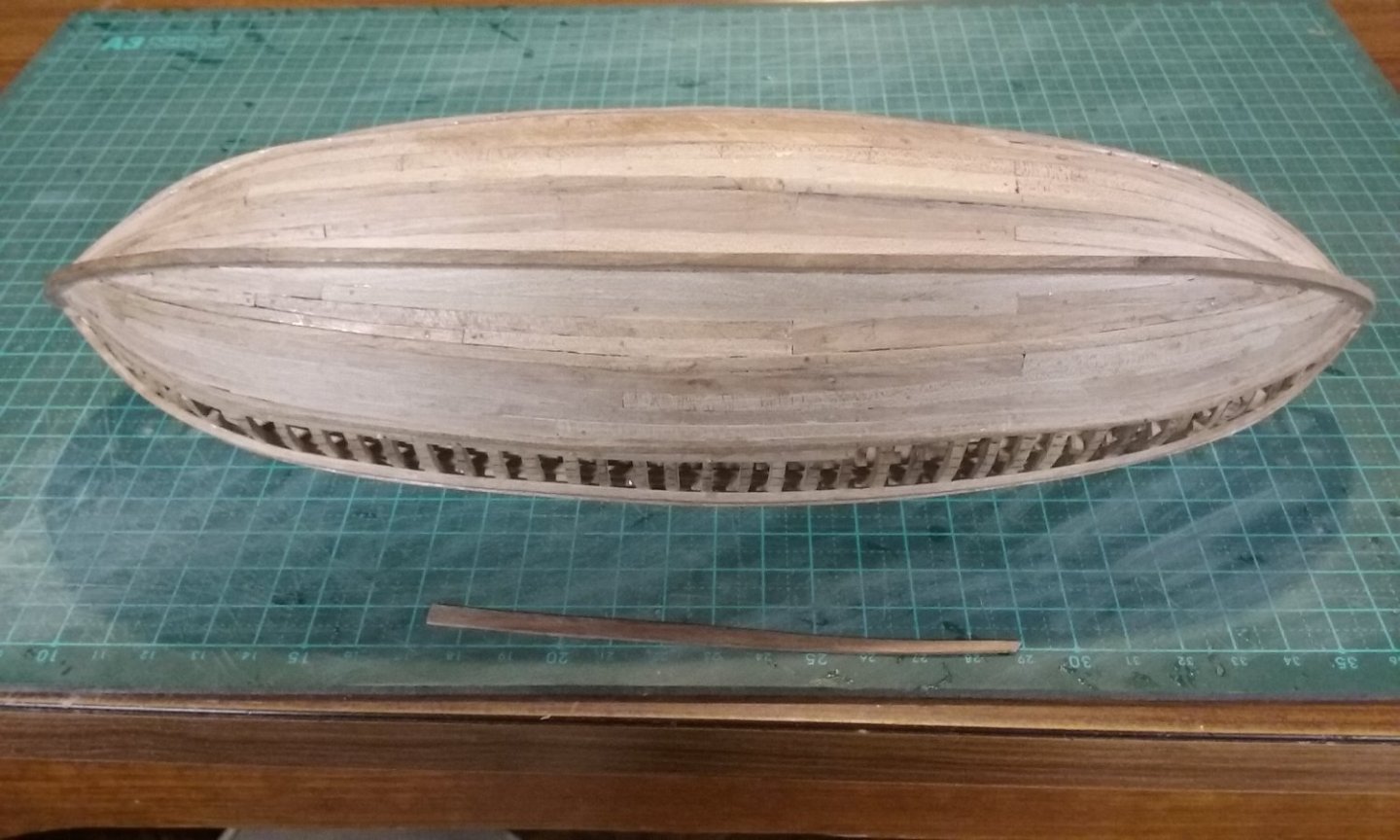
Ferrus Manus' question about drop planks got me thinking (don't get a swelled head, though, mate! ). I still don't have a problem with drop planks for mediaeval ships - innocent until proven guilty. But it made me look again at how I drew up the ship in the first place. One of the problems in drawing up your own plans from scratch, particularly for a ship which no longer exists, is that you can't necessarily see that you're designing problems for yourself into the build. Having re-looked at the configuration of the wales at bow and stern, I found that I've rather painted myself into a corner without realising it. Let's have another look at my original drawing. Each of the curved lines along the hull represents a wale. Look at how the space between them narrows, particularly at the stern. So the strakes have to get narrower and narrower - and at some point they have to be so narrow that it's a better idea just to drop one or more planks, as shown in the photos below. Note how very narrow the space between the wales is at the stern. Bow: getting a little tight. Stern: Really running out of room here. Ideally, the wales should be parallel throughout their length, so the strakes wouldn't narrow at all, but this is of course impossible in something boat-shaped. But it should be kept in mind when working out the configuration, particularly of the wales. Had I done so I don't think I would have needed anywhere so many drop planks - perhaps even none (can't be sure of that, but perhaps). I came across this problem in my dromon build, but I don't think I really learnt the lesson well enough at the time. Now I've had it shoved in my face - in future I'll be keeping this concept very much in mind. On the other hand, I did feel I needed practice with making (and understanding) drop planks, so it's certainly not wasted effort. Steven

-
I hadn't but it's a very good idea. I really don't think wood would be suitable - it splits too easily - but card might do the job. Thanks for the suggestion. Steven
-
Yes, it was a printing press, and they screwed it upwards to support the cracked beam. Yes, the state of knowledge has come a long way since 1957. But not a bad job for what was known at the time. Steven
-
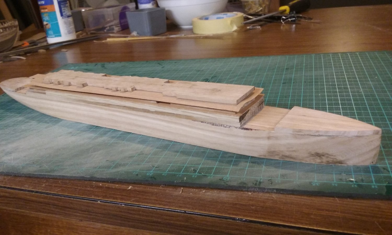
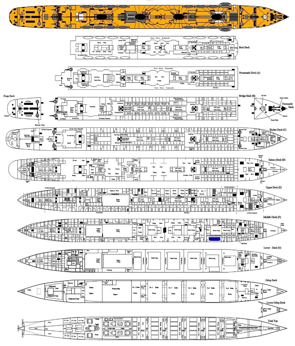
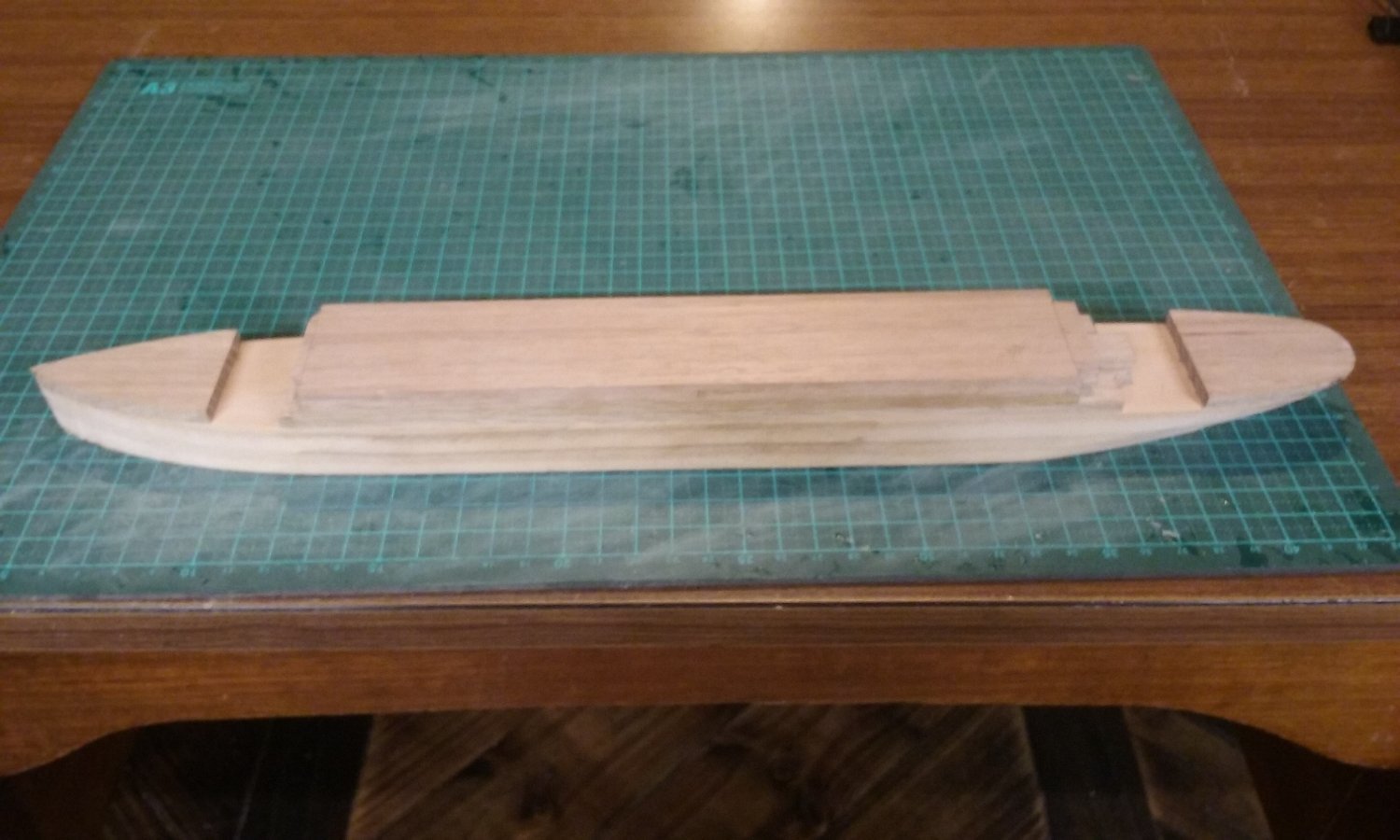
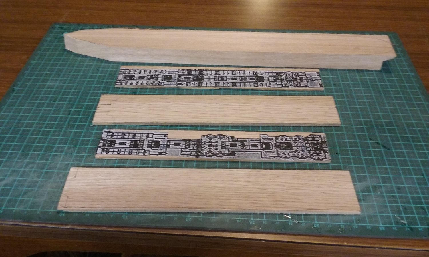
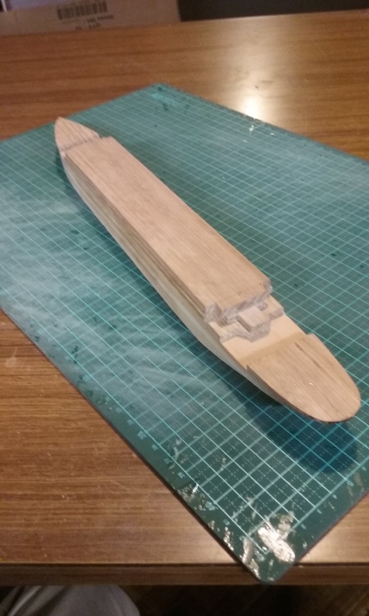
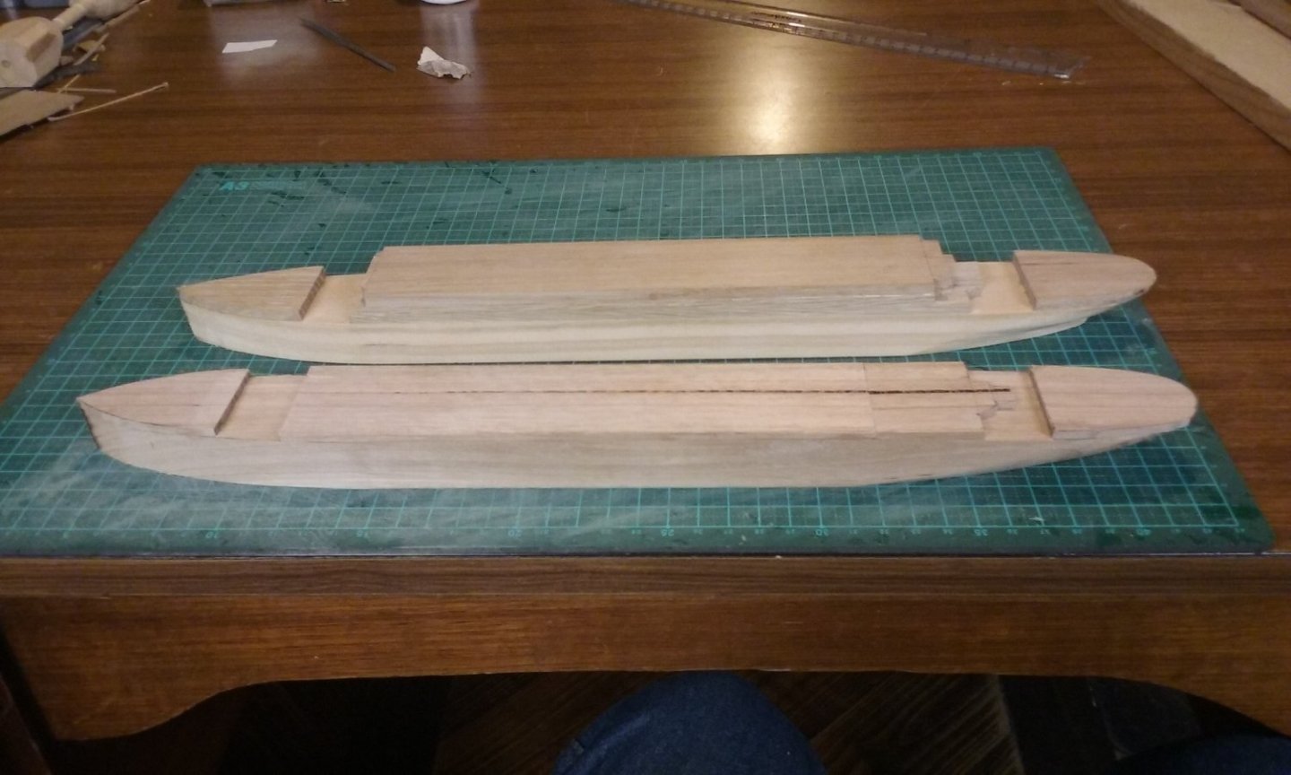
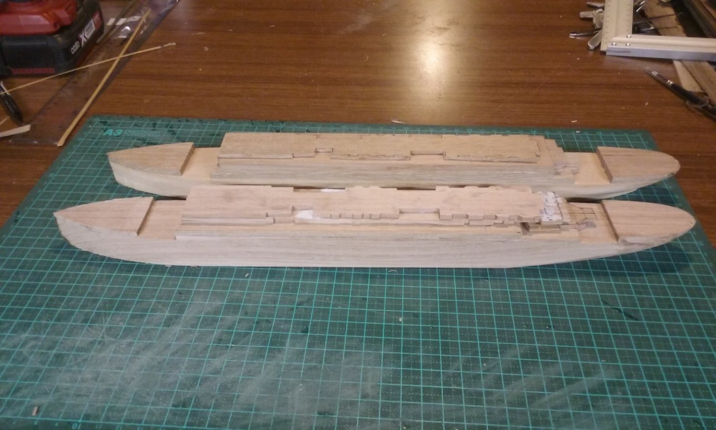
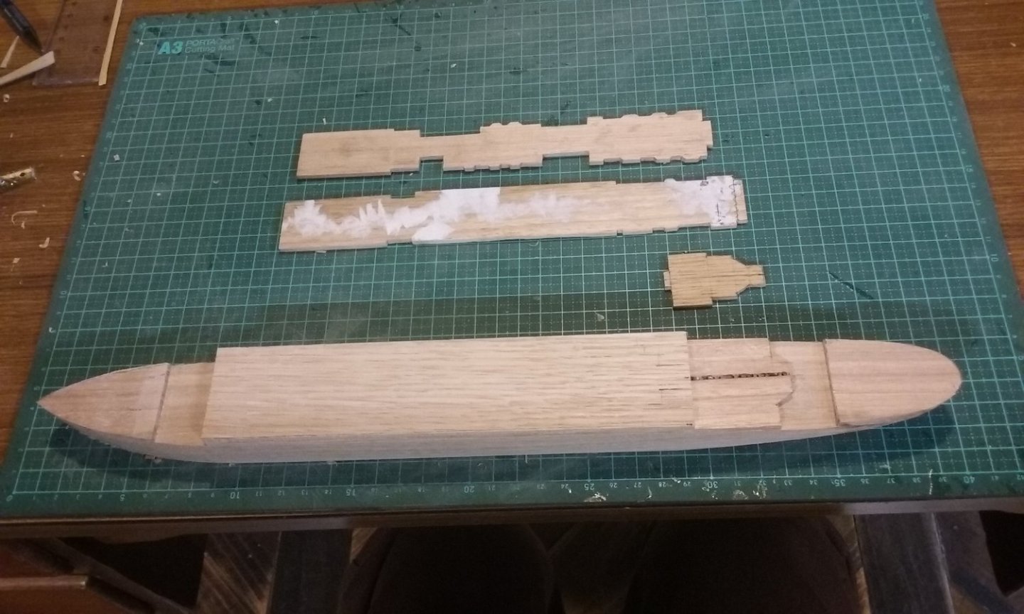
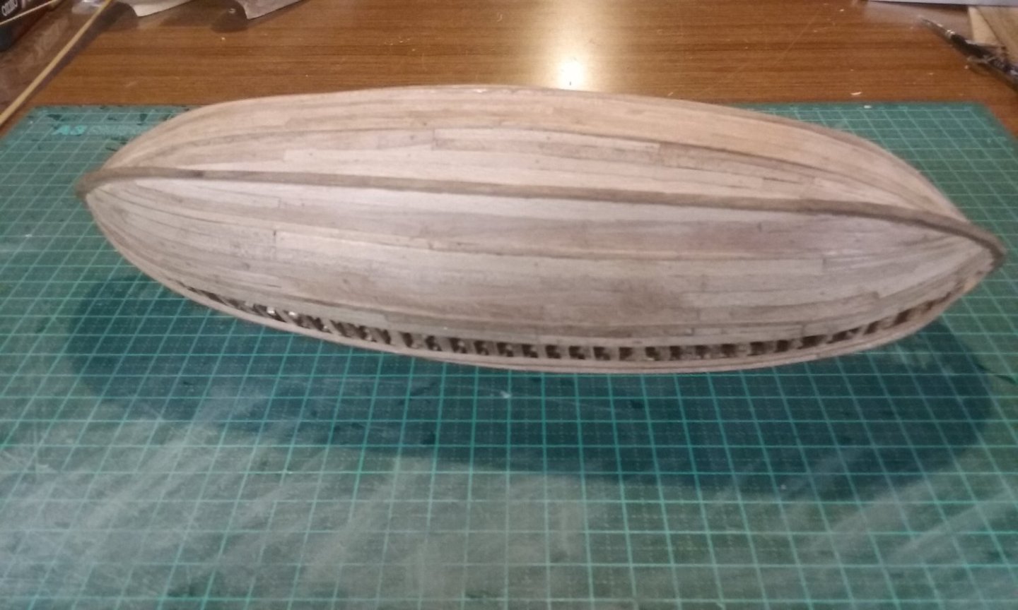
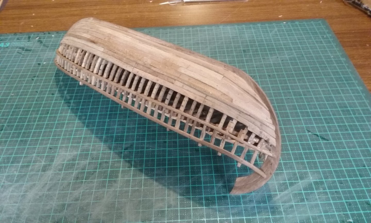
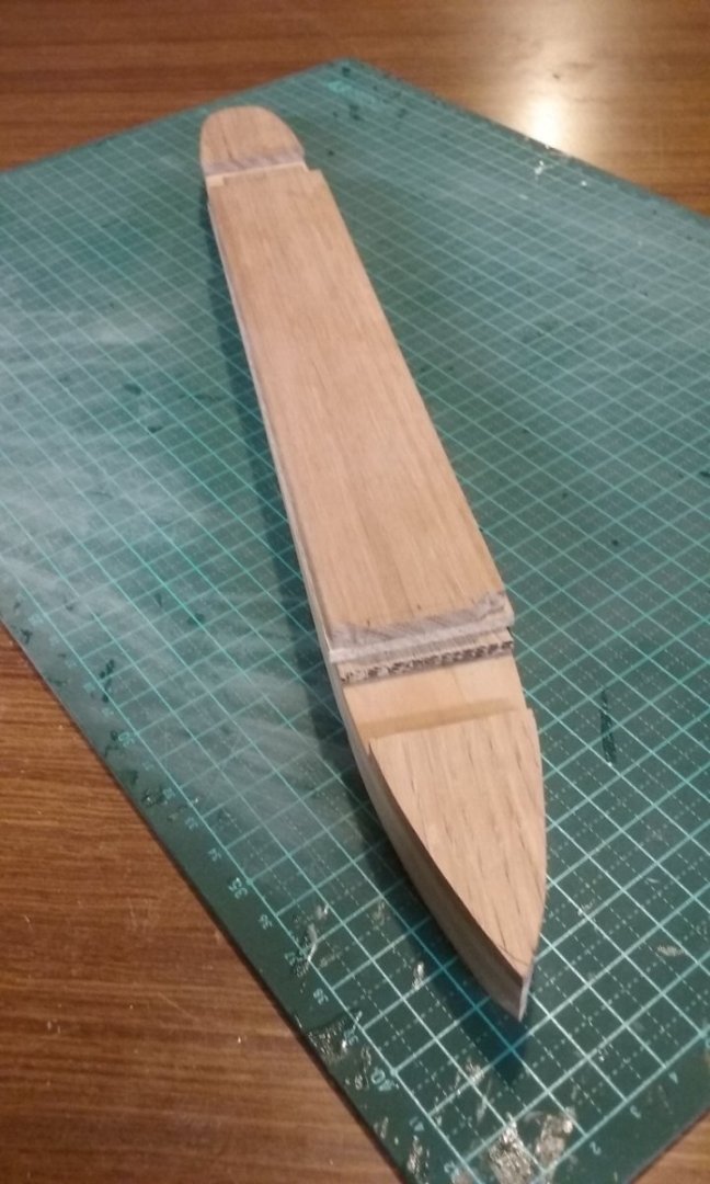
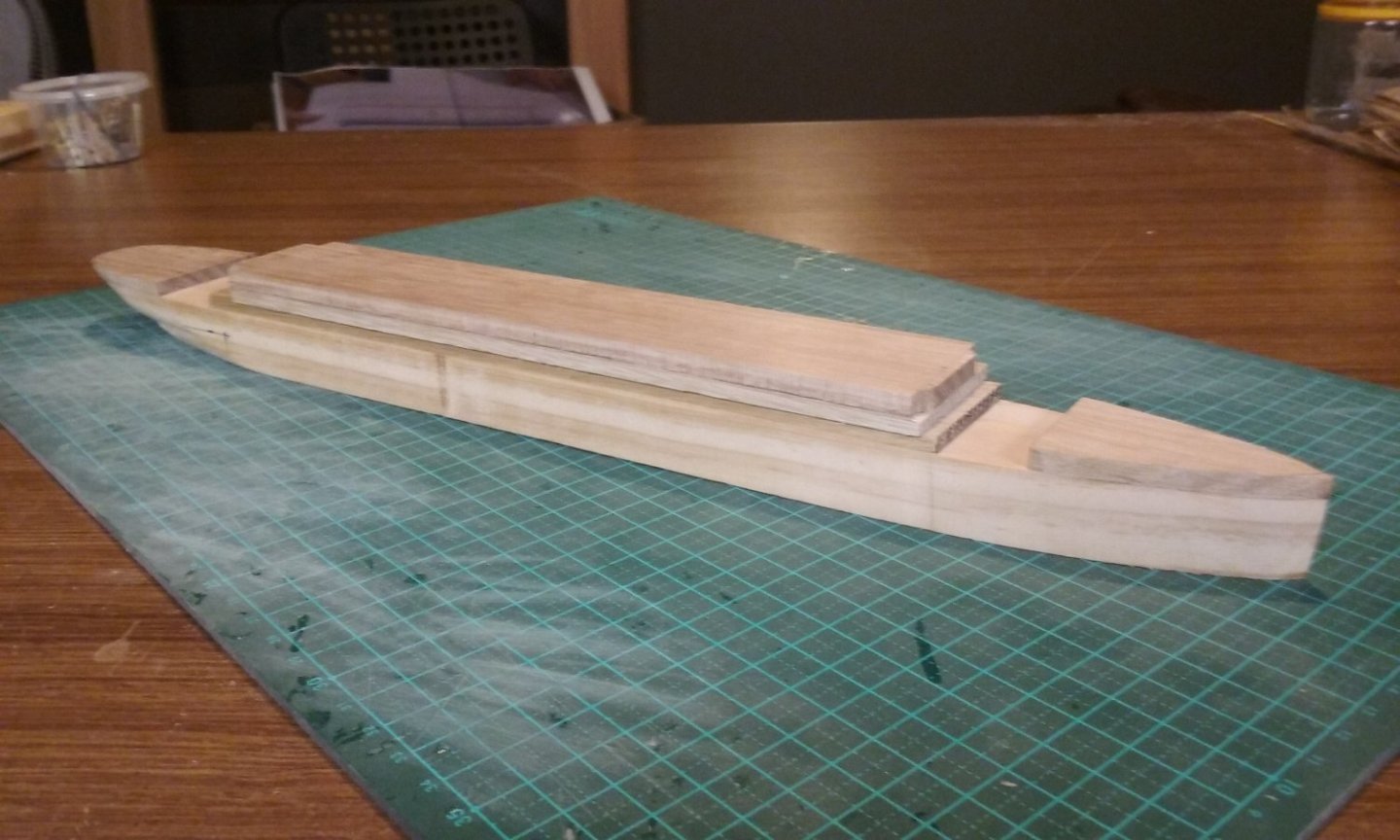
This thing is really doing my head in. Oh, for simple mediaeval models with only one or two decks visible! I'm still trying to reconcile the deck plans with how everything is configured in three dimensions, and it doesn't help that the plans I have don't agree with each other, or that due to inaccuracies in the printing process the deck plans in a given drawing don't line up with each other properly (sigh). Anyhow, I'm still continuing with the two versions - the first one is definitely wrong (for a given level of 'wrong'), but should be able to be completed and sold separately from the one I was commissioned to make. It's all solid. The other (foreground) will show the promenade decks, which need to be made separately and added as separate (very thin) layers. The line of dark wood at the top of this one will be hidden by layers above it, so I'm not bothered about it. Here they are with what I'd fondly supposed was the superstructure above the boat deck (top deck) but now turns out to be the First Class promenade deck. I've just discovered that the boat deck is yet another deck at the top I hadn't realised existed, and which I now have to make, along with its superstructure. First ("solid") version. Second ("decked") version. I've been trying to keep the promenade decks as thin as possible so the ship doesn't get too tall, but as you can see, there's a limit to how thin they can be made - one of them now has a 'wave' in it and will need to be replaced with a new one. These are of course dry fitted. I'm not going to use glue until I'm much more sure I've got it right. Nonetheless, I'm (slowly) making progress in getting it all sorted out. All good. She'll be right. But I have yet to figure out how to make the pierced "bulwarks" that run along the edges of the promenade decks. Steven

- 27 replies
-
- 10
-
-
A creditable result for a difficult paint job. I know how hard it is to do this, from personal experience. As a humble merchant ship she probably didn't have this elaborate a paint job, but this is a display piece after all, so it should look good. The "raw timber" in particular looks good. I agree about adding "rails" for belaying - do you mean on the inboard side of the bulwarks? After advice from other members of this forum, that is how I did most of the belaying on my Great Harry (75 years earlier - though Mayflower is likely to have been an old ship in 1620 - as attested by the cracking of one of the main (deck?) beams during the voyage). Steven
-
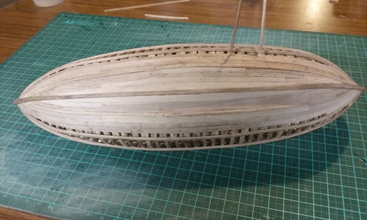
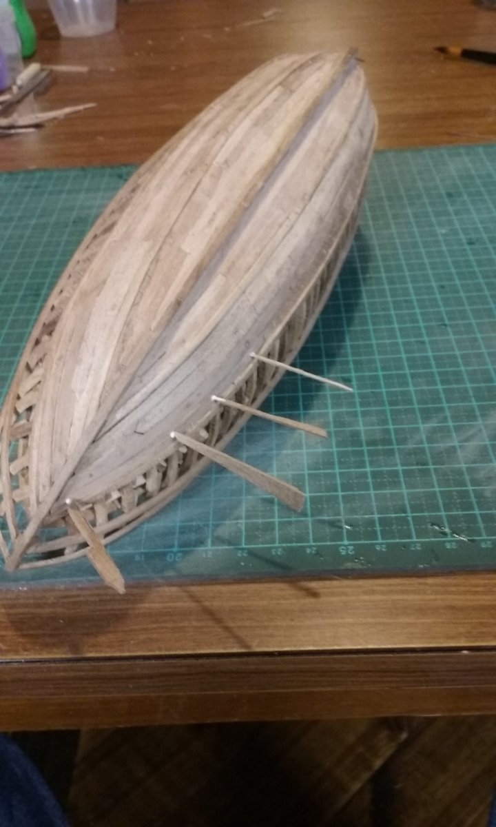
And remember - though this principle can be abused (for example to justify Celtic Ninjas), it's still true, particularly for archaeology, that Absence of Evidence is not Evidence of Absence. (It used to be believed that women in the 17th century didn't wear knickers, because none had been found. Until a pair was found, consigning that theory to the dustbin of history.) More planking. Up to the second wale. And onward, ever onward. Steven


- 508 replies
-
- 17
-
-
Welcome to the world of wooden ship modelling! It won't be the last time you split a bit of wood, but don't be concerned, it happens to all of us and we seem to survive somehow. These slotted pre-fabbed keels can be a bit fragile that way, unfortunately, which is why I advised against making the slot any wider. But your solution for the transom sounds like a good one. And yes, timber is a wonderful medium - unlike with plastic kits, if you don't like what's in the kit, you can make a replacement. Yes, that does seem a bit strange. But I think you're right putting packing of some sort in place. Don't want to break the keel! Keep up the good work. Steven
- 24 replies
-
- 1
-
-
- Ships boat
- Ships of Pavel Nikitin
- (and 1 more)
-
Nice seeing the Meteor in her current state. Whether you keep working on her at the museum or at home, keep us informed! And yes, another vote in favour of the restoration. Steven
-
Hmmm, difficult question. I suppose you could try thinning the thick support? I think opening up the keel slot might make t too weak. Cutting the decorative piece in two might be better - the sternpost seem to cover all the way to the top of the decorative face. It would have to be pretty precise cutting, though. Assuming the frames fit in the slots there doesn't seem to be any good reason for thinning them further. You'd just giver yourself extra work for no extra benefit, particularly as - if the photo on the box is to be believed - the frames are hidden anyway. Steven
- 24 replies
-
- 2
-
-
- Ships boat
- Ships of Pavel Nikitin
- (and 1 more)
-
Nice to see the planking complete. Looking forward to further progress! Steven
- 134 replies
-
- 5
-
-
- sea of galilee boat
- SE Miller
- (and 1 more)
-
Hmm, good point. Different drawings in different scales, but could be reduced to lowest common denominator. As Young Frankenstein said - IT --- COULD --- WORK!
-
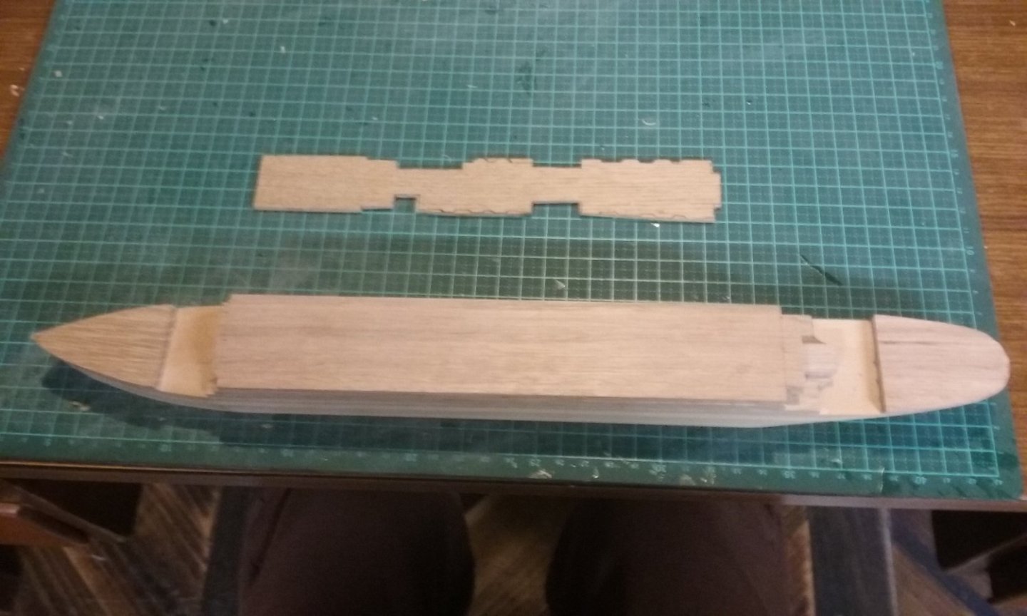
Oops. Further perusal of the plans has made it clear to me that I still hadn't fully understood them. In fact the superstructure is only a little too low, but the structures between need to be looked at more carefully. Which I'll do tomorrow.
-
Beautiful precise work, Silverman! Yes, the knees look really good now. And your baling solution is very well thought out. Steven
-
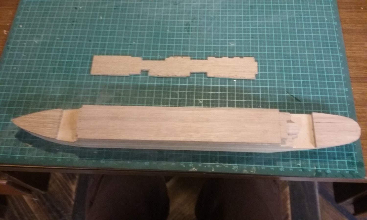
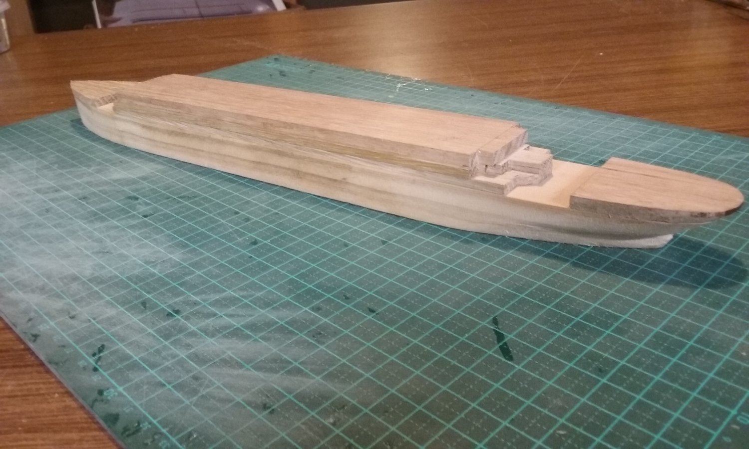
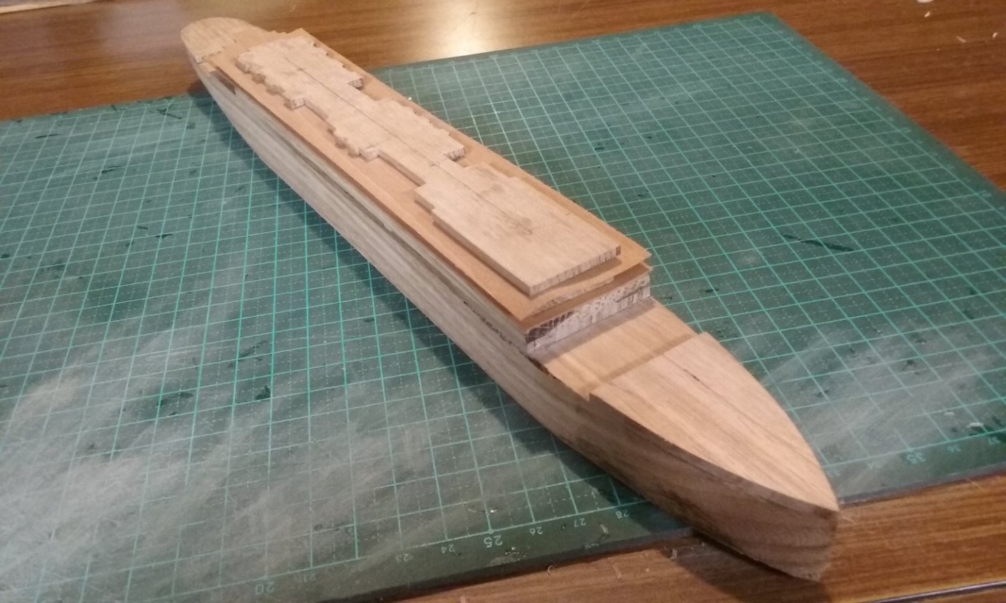
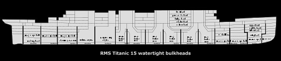
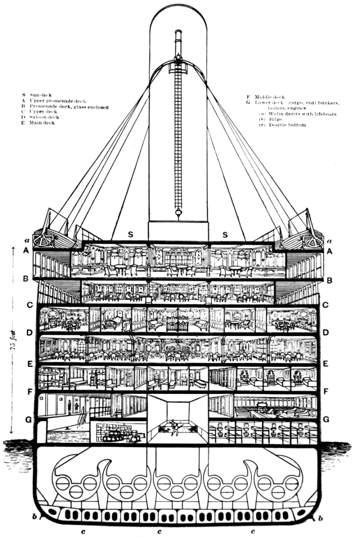
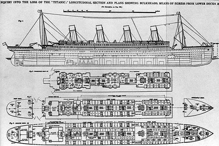
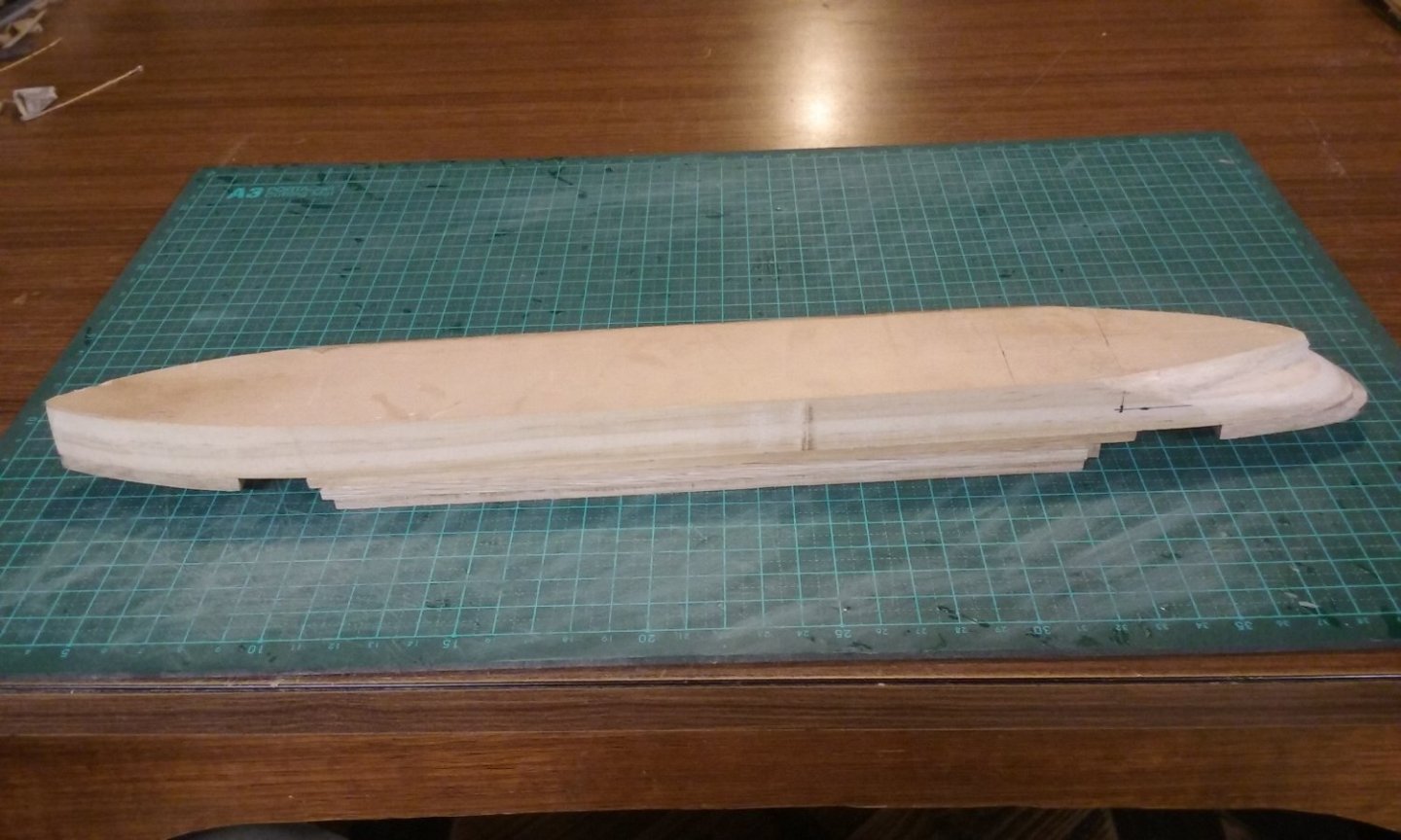
The title says it all. For the first time someone has asked me to make a model ship and is willing to pay cash money. Only a pittance, pin money, really - $200. But no worries, I'm not doing it for the money but for the experience and challenge. Second "modern" ship - the first was HMVS Cerberus - see build log This time it's the Titanic This is also a Men's Shed project, but this time I'll be paying only a percentage of the price to them (for use of facilities and materials), the rest for pin money, as I was directly commissioned to build it. A young guy I met has a girlfriend who's a total Titanic freak and he had the idea that a model of the ship would be a nice Chrissy present for her. And I'm happy to oblige. However, it has meant the Couta boat has had to go on the back burner for a while. It's nearly finished - the sails are cut out, but I have to sew (or get someone far more experienced to sew) them, add them to the gaff and boom and add the rigging. I'll get around to it whenever. There are plans and photos on the Net of the original ship - not terribly good, but adequate for a $200 model, which will be 380mm (1'3") long. The first thing I hadn't realised until I downloaded these was how long and narrow the ship was! Took me totally by surprise. Here are the plans I'm working from. So, off I went cutting out wood and layering the decks - only to find that in my main source of info - the two sets of deck plans - two of the deck layouts showed not only the deck itself, but the superstructure between it and the deck above. So I'd missed out two entire decks - the superstructure was two decks too low. Annoying, as I'd put a lot of work getting that beautiful stern right. But as I'd glued it all together very securely before I realised my mistake, there was no way of pulling it apart and adding the extra structures. So I had to start all over again, but at least this meant I could correct a couple of other errors I'd become aware of caused by the inaccuracy and imprecision of the plans. So here we go again, this time with the extra outlines. Watch this space. Steven PS: If anybody can let me know the maximum and minimum diameters of the (oval section) funnels, I'd be very grateful.


- 27 replies
-
- 12
-
-
She was terrible in Rivers, and perhaps even worse in The Man From Snowy River - very much a matter of "Show us your other facial expression, dear!" But by Sea Change - in which she starred with David Wenham (alias Faramir) - she had developed quite a sharp comedic gift. Steven
- 18 replies
-
- 1
-
-
- Pevensey
- World of Paperships
- (and 2 more)
-
Beautiful work, Richard. I remember All the Rivers Run very well. Fortunately Sigrid Thornton's acting improved with experience.
- 18 replies
-
- 2
-
-
- Pevensey
- World of Paperships
- (and 2 more)
-
It certainly beats trying to make the ram out of sheet metal (of course, you could try actually casting the thing in bronze! ) Steven
- 536 replies
-
- 3
-
-
- Quadrireme
- radio
- (and 1 more)