


Rick01
-
Posts
637 -
Joined
-
Last visited
Content Type
Profiles
Forums
Gallery
Events
Posts posted by Rick01
-
-
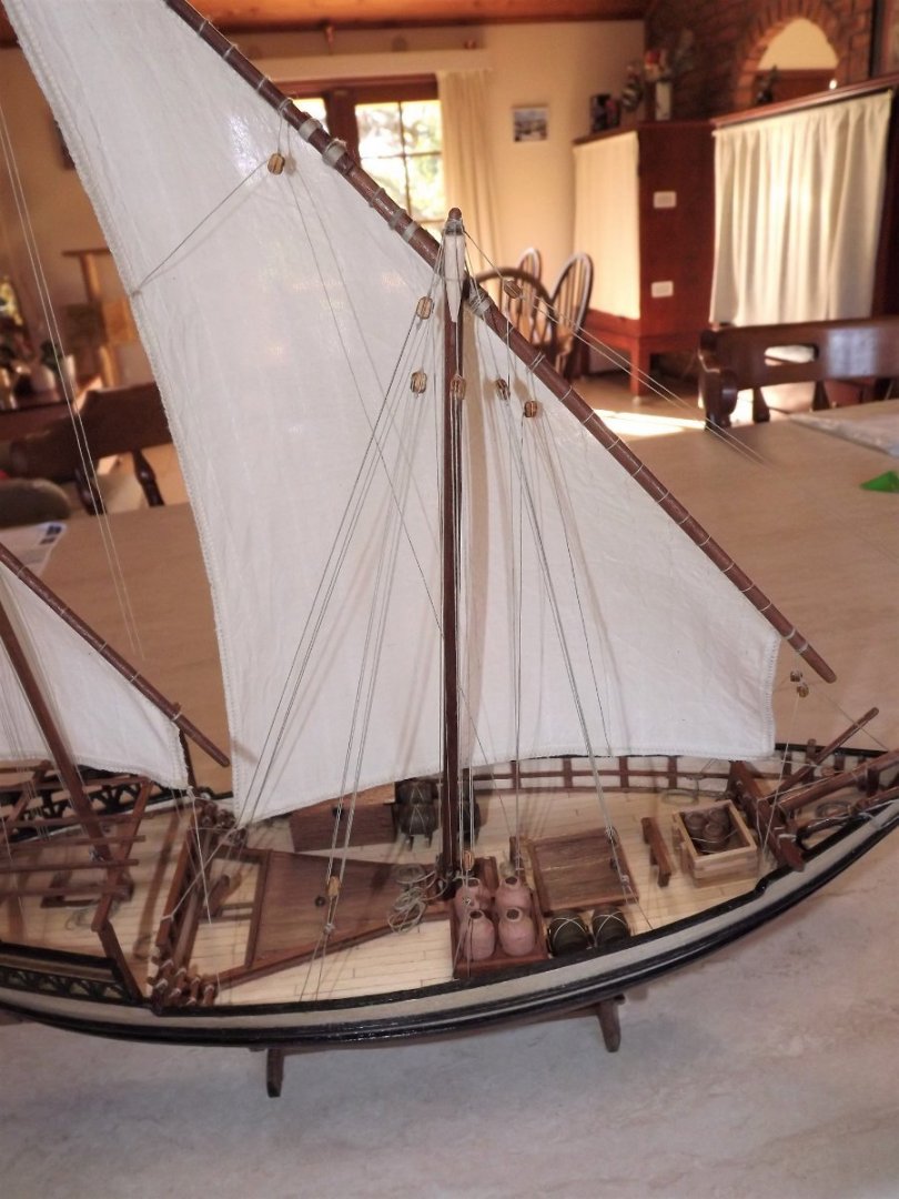
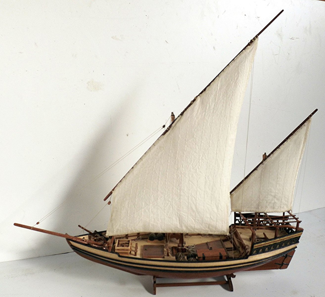
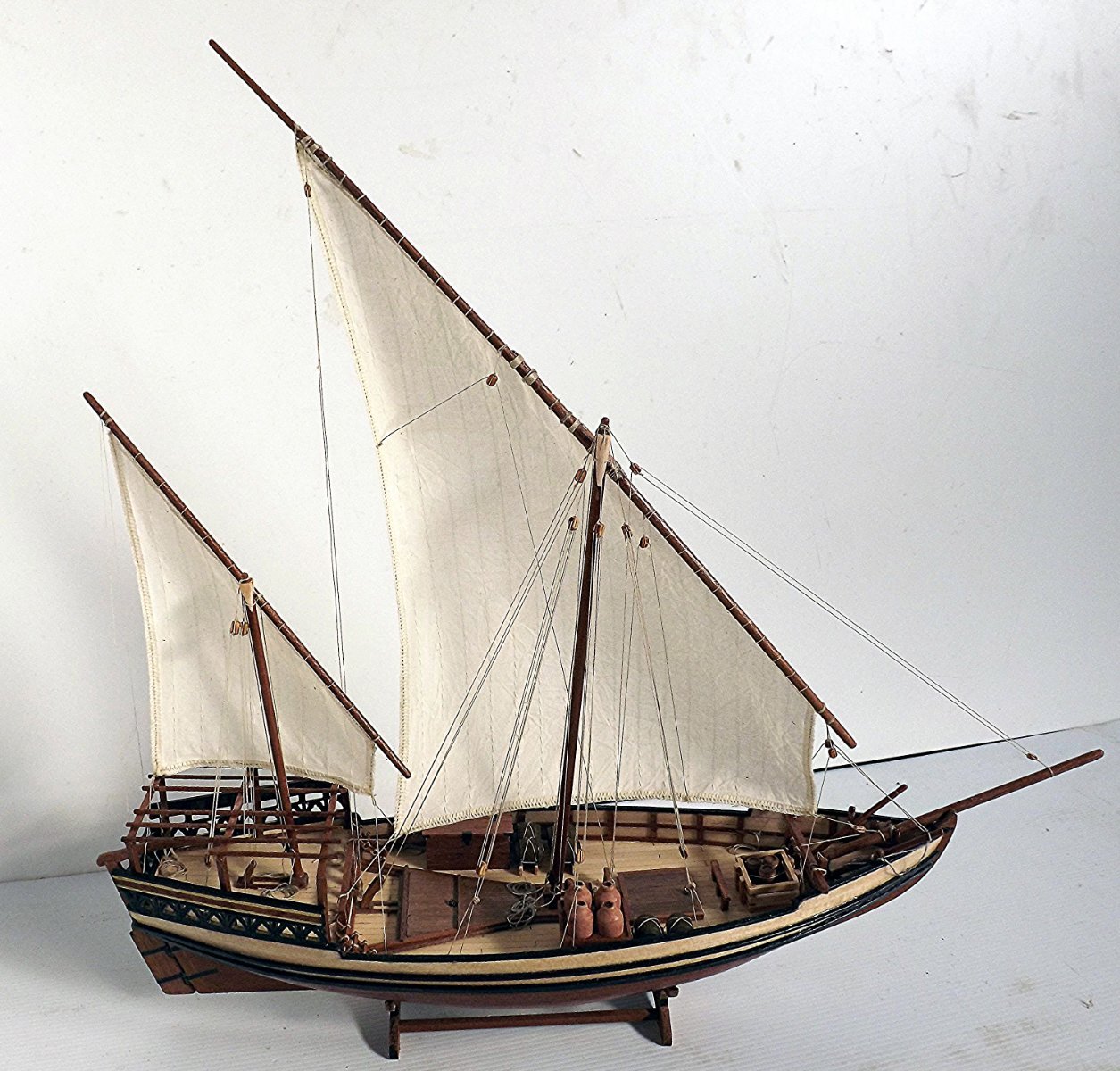
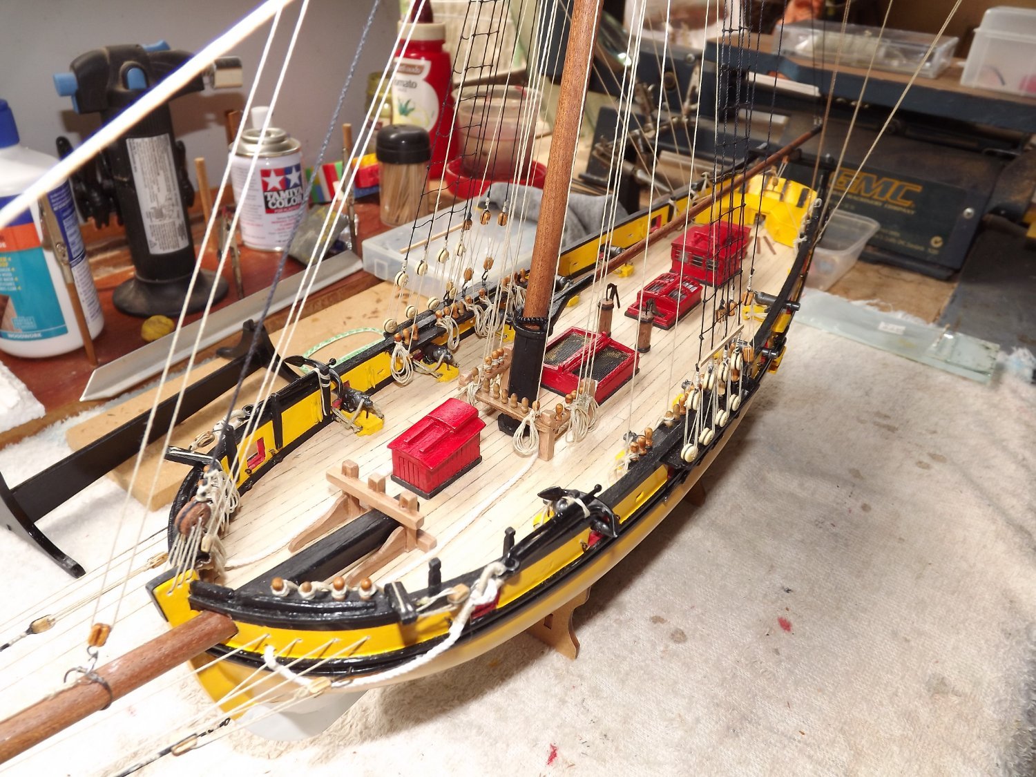
Finally finished.


For anyone else attempting this model I'd strongly recommend a good magnifying glass to read the instructions and study the pictures. A lot of research on what these vessels actually look like, including the rigging. Measuring and dry fitting items at every step. Before gluing anything check ahead in case you find that fixing the item may interfere with later actions i.e. deck furnishings.
Other than that - enjoy.
Rick
-
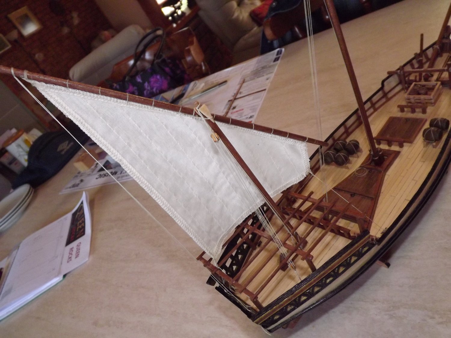
First assemble, then dress the yard. According to the instructions it's assemble,sew on the sail, then mount the yard.After that then add various blocks once the yard has been hoist. Much easier however if you fully assemble all items that are attached to the yard before hoisting it.

It was then just a matter of sewing on the sail, hoisting the yard and then commencing the rigging.
 I
I
I re-arranged the siting of the sea chest and amphora so as to not interfere with any rigging and the mast stays are only mounted on the starboard side of the ship (see my previous post). I also re-sited a some of the bow rigging in order to effect a free flow of the cables and a more effective control of the sail.
A couple of shots of the finished item will follow.
Rick
- yvesvidal, Joseph F., Prowler901 and 2 others
-
 5
5
-
Finally pinned down a couple of illustrations of dhows to help with rigging the main mast/sail. This is a short description of an Indian two-masted "dhow" measuring 40 ft (the kit measures 70 ft along the deck) https://journals.openedition.org/archaeonautica/594?lang=en . This is a 60 ft modern dhow clearly showing the rigging to the main mast https://www.eastafricayachtcharters.com/60ft-zanzibar-charter-boat-dhow . In both variations it's pretty clear that there are no stays on the "sail" side of the mast. I've also seem a few photos of working decks but no good close-ups, these seem to show that they are pretty untidy including ropes piled rather than neatly coiled/hung from gunwales.
I'm working on the main mast and spar and should have something further to post shortly.
Rick
-
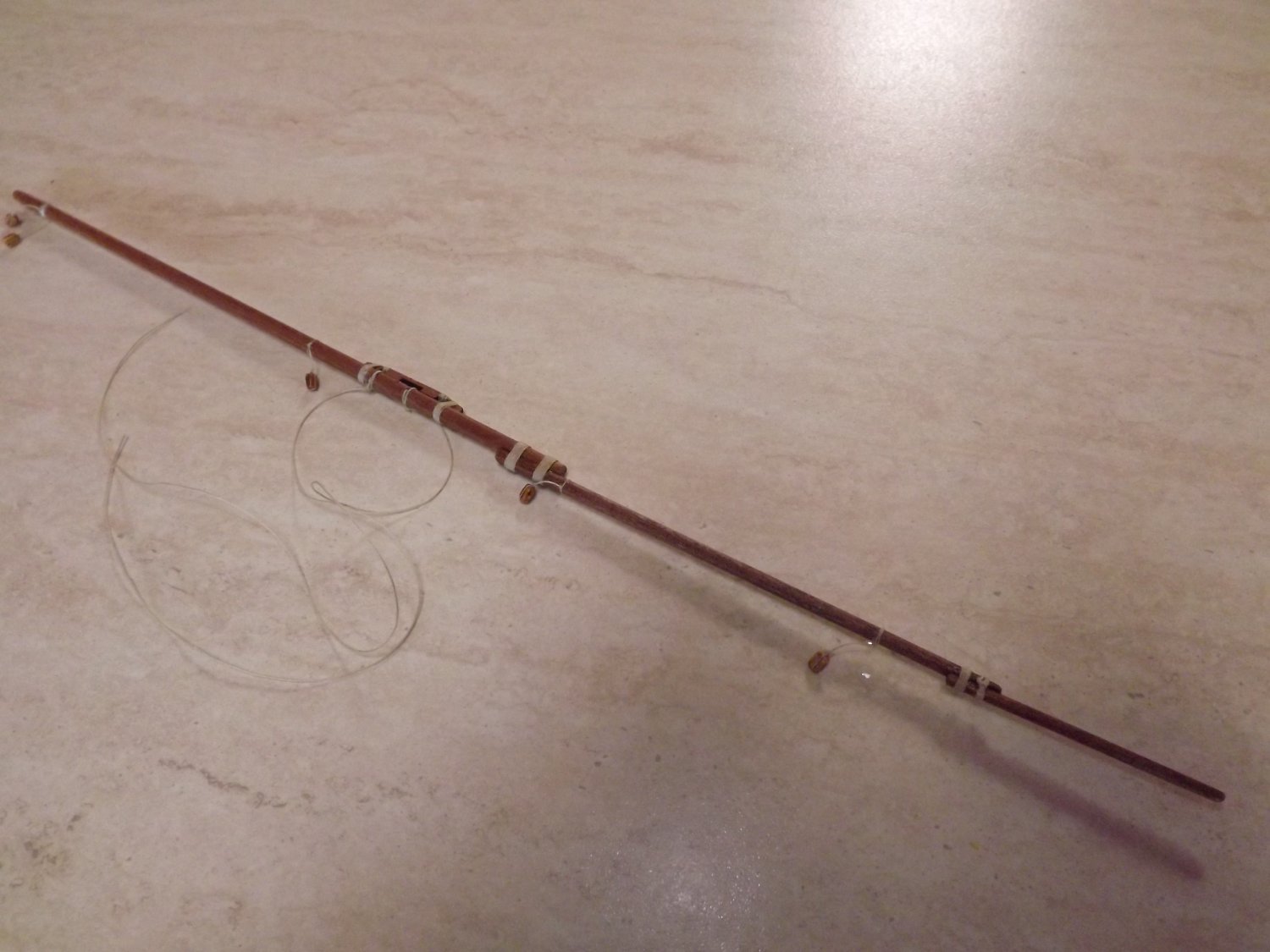
Well after considerable searching on the net the only half way constructive advice I could find was this nice item here.
It seems that the jury is out on a number of items concerning rigging this type of sail and thus I'm working on what (to me) seems common sense.

First I stripped back the cover supports as they were fouling any run that I attempted for control of the sail foot and spar tip. I then added two more cleats to the mast, this way the sail hoist, a second rope used to hold the spar against the mast, plus the rope which tensions the mast brace, all have a separate securing point. In the foreground is a further brace for the mast, on the opposite side to the sail. There will not be one on the other side.

Next I built a strengthener with cleats for the top of the fancy work on the counter.

This was added as two sections to allow the rudder bar free play. Despite appearances the cleats are inboard, not on top of the reinforcing strips.
The end result has allowed me to rig the lines controlling the sail foot and spar tip to be added, without (again) using one cleat for two lines and without rubbing on any woodwork.

The end result isn't too bad and once I've dealt with the sail to give it the impression of wind filling it, all the lines should run freely. I know the sail is pretty average but it's past my ability to construct a better one, arthritis in my fingers is severely hampering my dexterity.
Rick
-
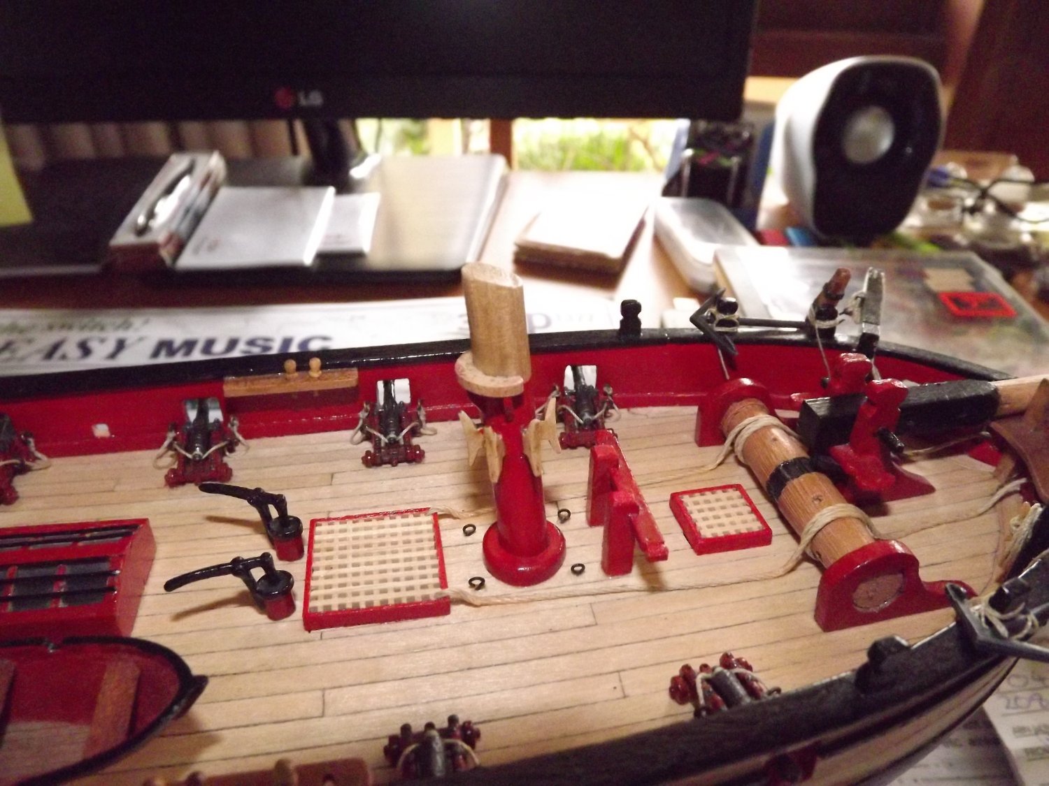
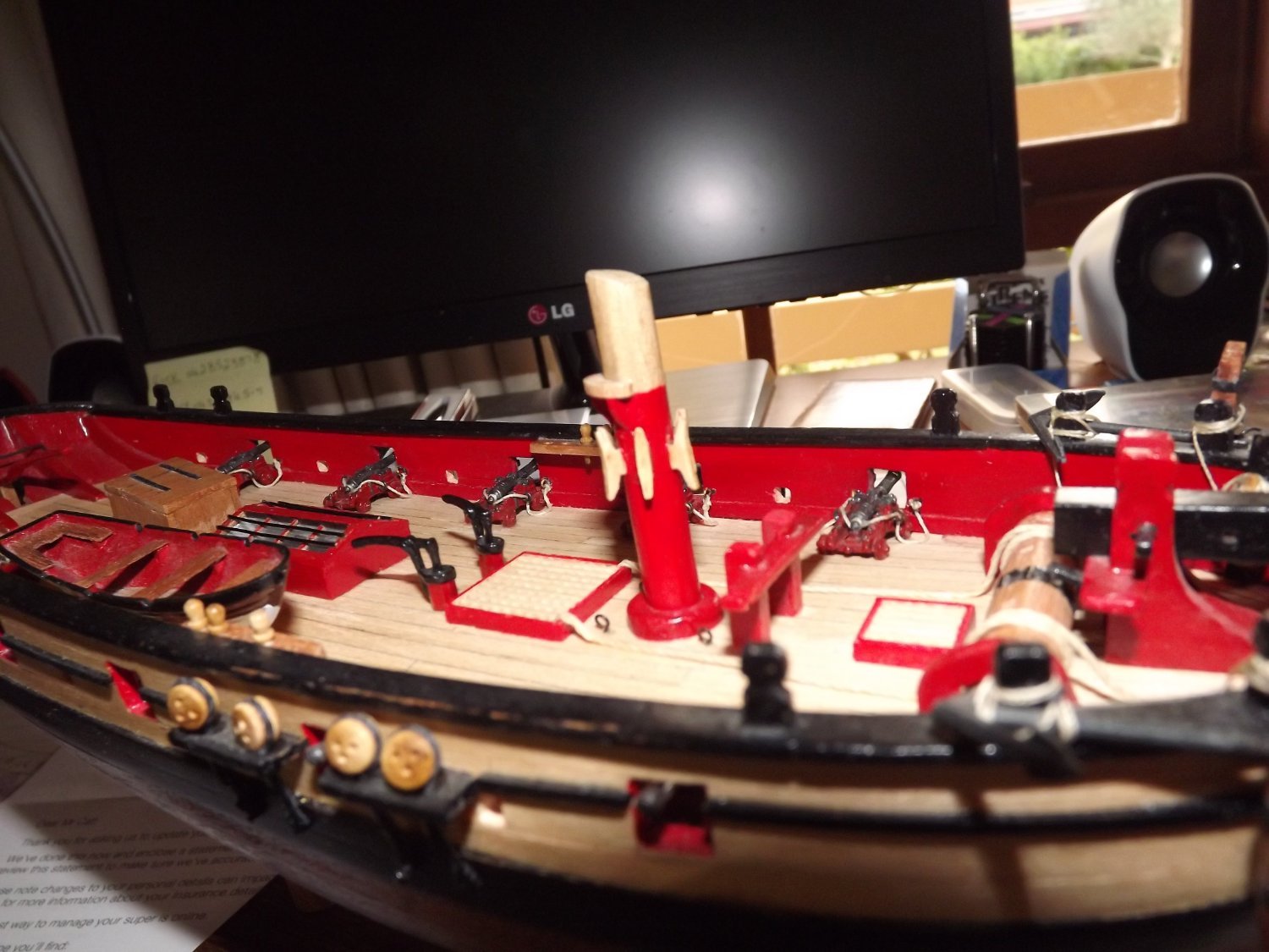
Things are now about to come to a screaming halt! Again I've amended the build slightly, the "shade" area at the stern now consists of a number of flat slats, not the convex cover shown in the plans. 99.9% of the actual dhow photos that I've seen use the slats and only a very few use a tent like structure and these latter seen to be tourist boats. Masts have also been stepped.
Spars and rigging next and this is where I have major problems.
.thumb.jpg.5106ed5e6d884a0a5e96a2ae0b771b8f.jpg)
As you can see, the instructions are pretty poor and illustrations as clear as mud. The bottom left illustration seems to indicate a hoist for the spar coming down to a cleat on the mast. Now check the next page.
.thumb.jpg.470d233fa92f94bffff73af896af3e35.jpg)
Here illustration 2 and 3 show what appears to be a brace for the mast, again terminating on the same cleat but over the spar hoist. Surely you don't release the mast brace every time you lower or raise the spar!
Nest problem is the two braces (green thread) shown at 4 and 5. If these are correct then the spar is effectively working fore and aft only. The same is shown later for the main mast/spar. Again every illustration of a dhow under full sail shows the spar as working almost as a square sail. So, at this point I'm off to find some sort of dhow rigging manual to try and clarify this area.
Rick
-
1 hour ago, Dave_E said:
I’m going to try and add some rope coils, however that will be after I build a jig and practice.
When making my coils for the belaying pins I make up a jig from scrap MDF . Standing on edge I put a number of small nails/pins in close to the edge and after making a coil of 6~8 loops, place it over a nail/pin hanging down. To shape it so that it sits somewhat realistically I then use white PVA glue and carefully pinch the coils into the required shape. make sure you do have a small space at the top so that you can use short length of line to tie the coil to the belaying pin. See the sample I posted further up this page.
Rick
- Dave_E and Keith Black
-
2
-
-
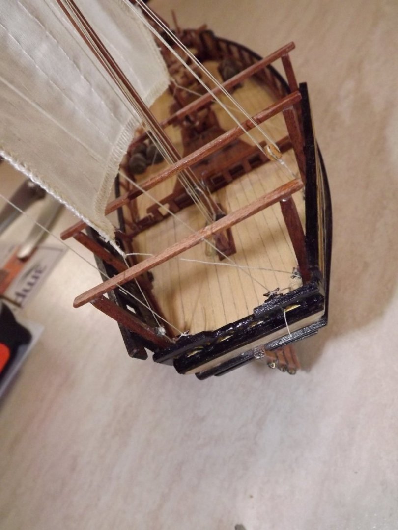
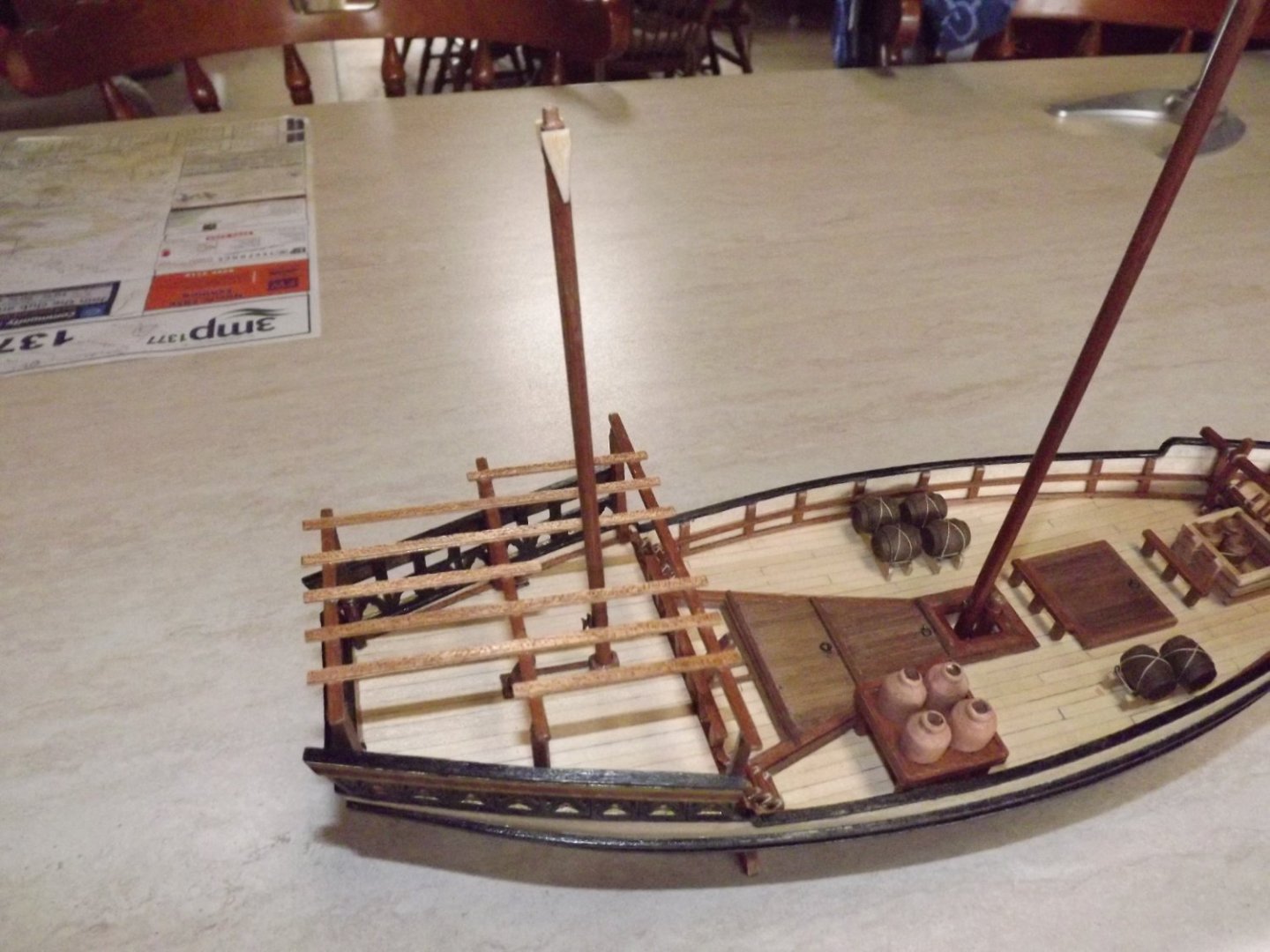
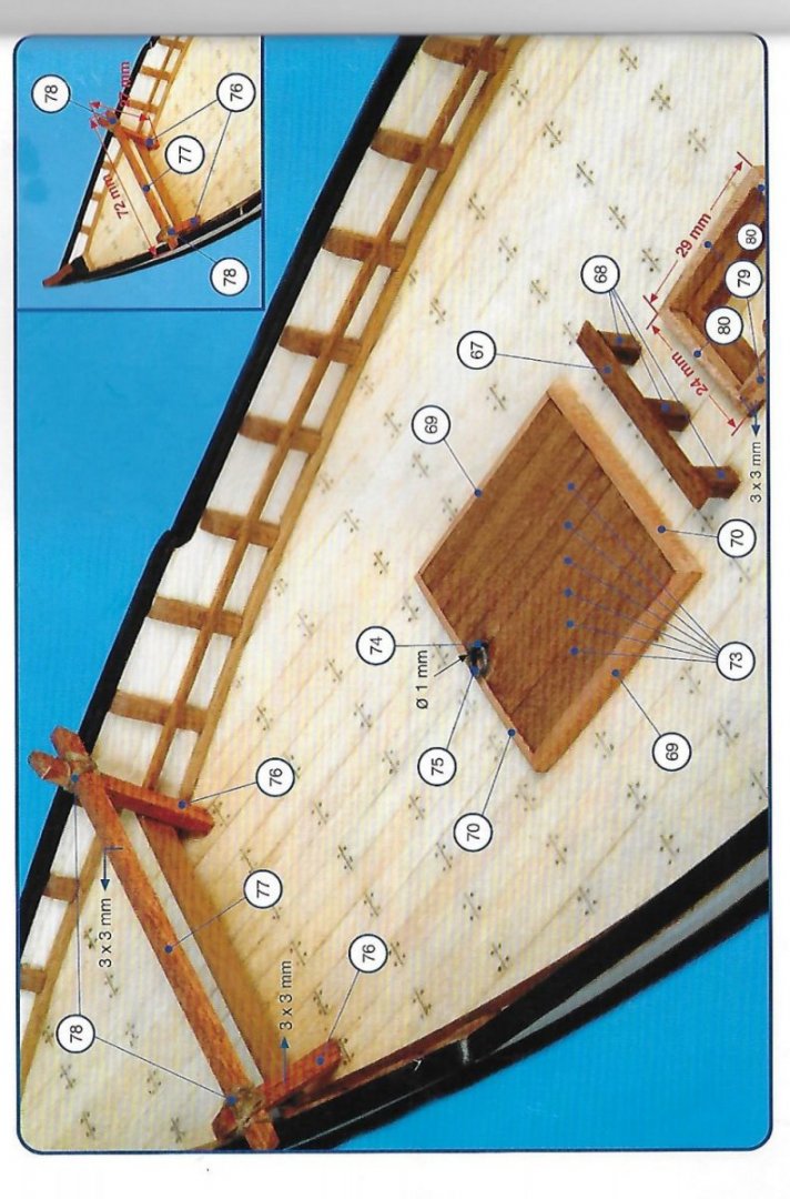
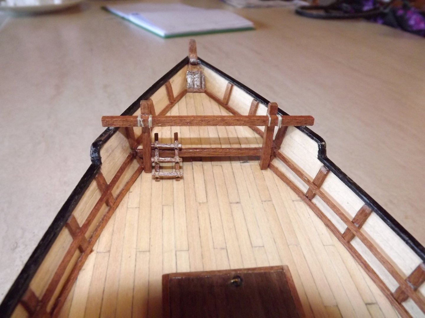
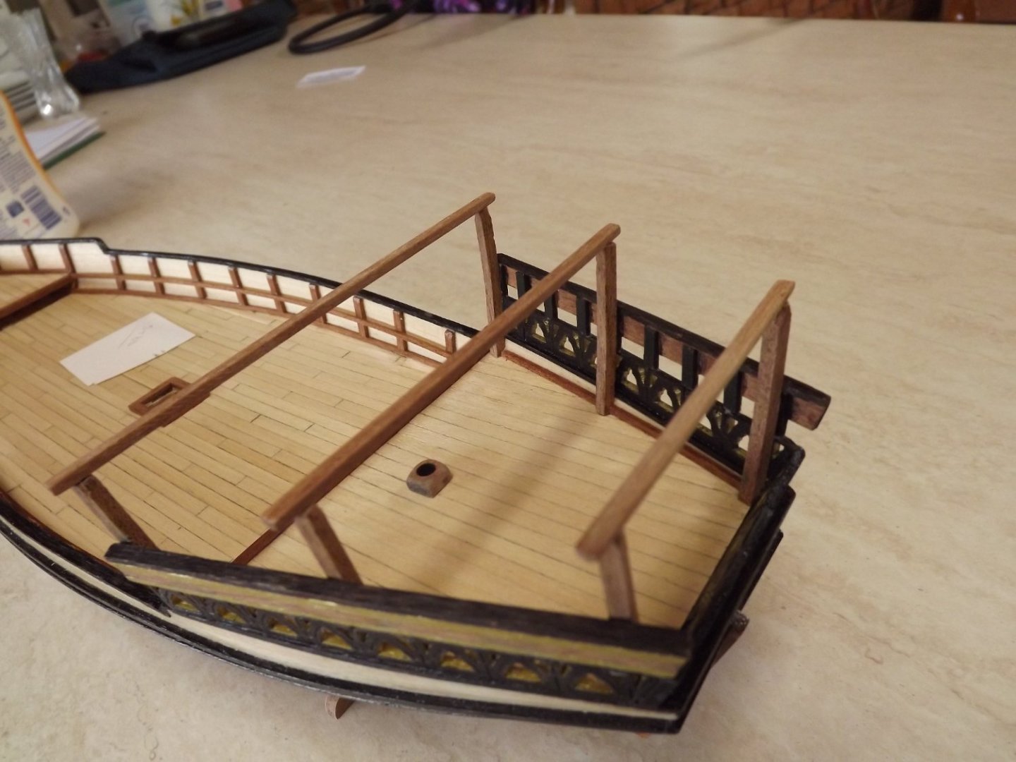
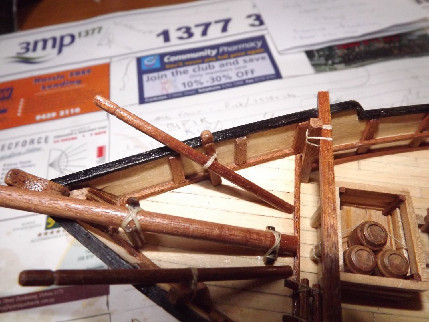
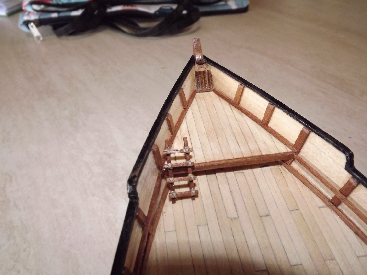
On to the fore deck fittings.
First get a magnifying glass, the plans are pretty small in this area and, unless you've 20/20 eyesight they're a pain!
I'll mount the anchor later as it's a poor casting and needs some attention. Looking closely, parts 117 and 118 need a slight groove for the rope to run in. Additionally I found that part 118 also needed another 2mm added as it did not project high enough over the gunwales at the recommended 18mm. I also added a lashing where the part 117 rests against part 118 although this is not shown on the plan. I did this after finding a number of photos on-line showing the deck of a working dhow where everywhere any fixture crossed another it was secured with lashings.
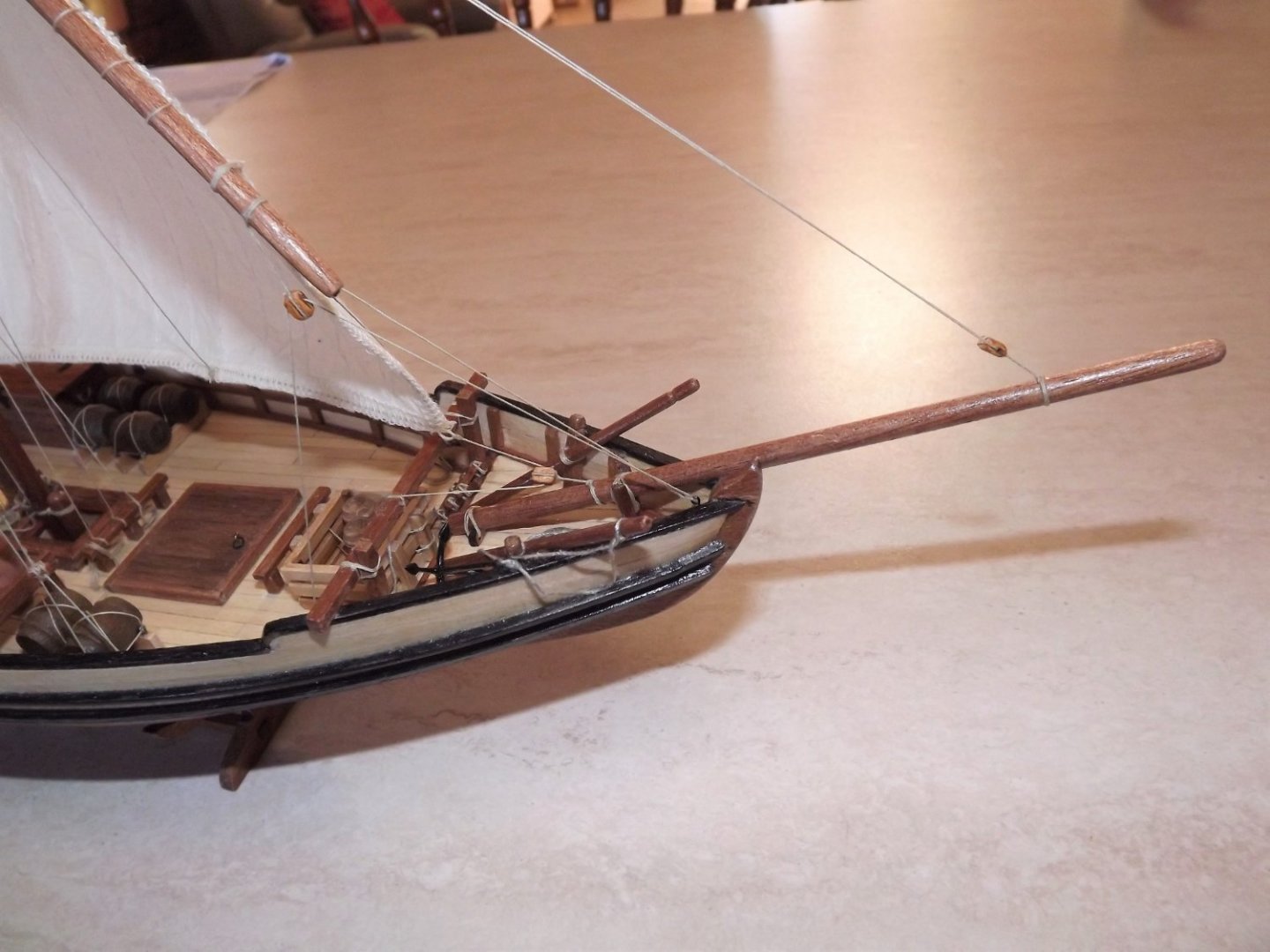
The next step was assembly of the bowsprit.
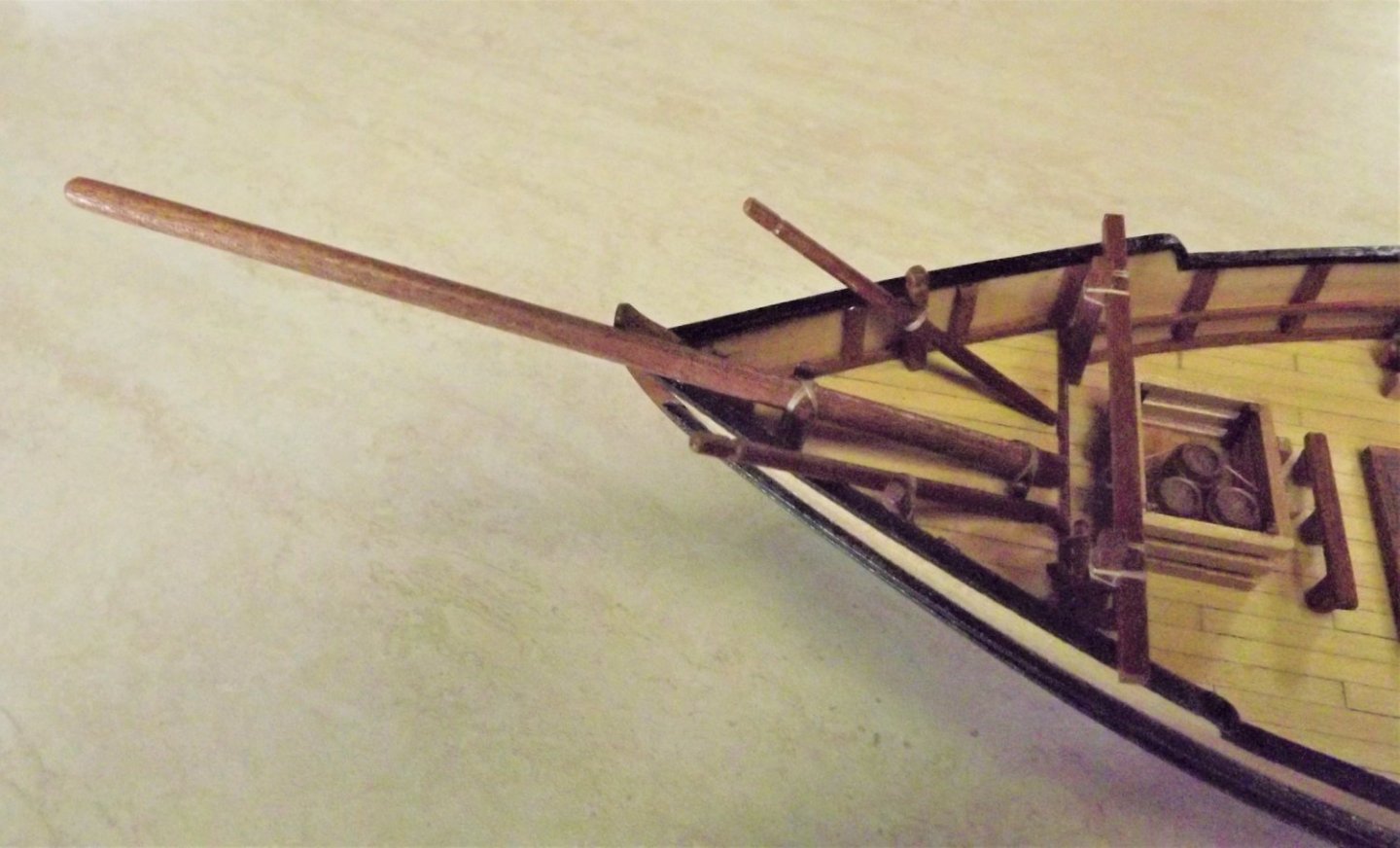 This appears to be only slightly tapered if at all and from what I could find on-line seems correct.
Having cleaned and shaped parts 130 through 133, I assembled them before mounting on the deck. The instructions appear to recommend mounting to the deck then lashing - try that and you'll tie yourself in knots with the attempt! Instead of using the brass wire (133) I used a wooden spacer, less of a problem than trying to drill the 1mm holes in very splintery dowel and also more likely to have been used on the real thing. It was a little fiddly getting the parts 132 the correct length but not impossible.
Rick
- Paul Le Wol, ccoyle, yvesvidal and 2 others
-
5
-
8 hours ago, Dave_E said:
Depending on how that goes, I’ll consider it.
At least make up a couple and give it a try. It just finishes off the rigging. It's basically a matter of making a coil of 6~8 loops round something like a thick pen, with 4~5 centimetres of line tucked under the loops. Tie it off to hold the loops together and use a little PVA glue to shape the rope into something resembling a natural fall. Once it's dried then, using the excess line hook it up onto the belaying pin, a little more PVA to position it and it's done. Fiddly I know but worth the effort.

Different ship, but you get the idea.
Rick
-
Are you going to add coils of rope where-ever you've ended any running rigging?
Rick
-
As someone else has suggested - ground up, middle outwards and front to back. All standing rigging needs to be completed first (but after such items as booms etc), then the ratlines and finally running rigging. This is similar to actual practice, after all you re building a miniature ship. It will be a little awkward but not impossible.
Rick
- Dave_E and Keith Black
-
2
-
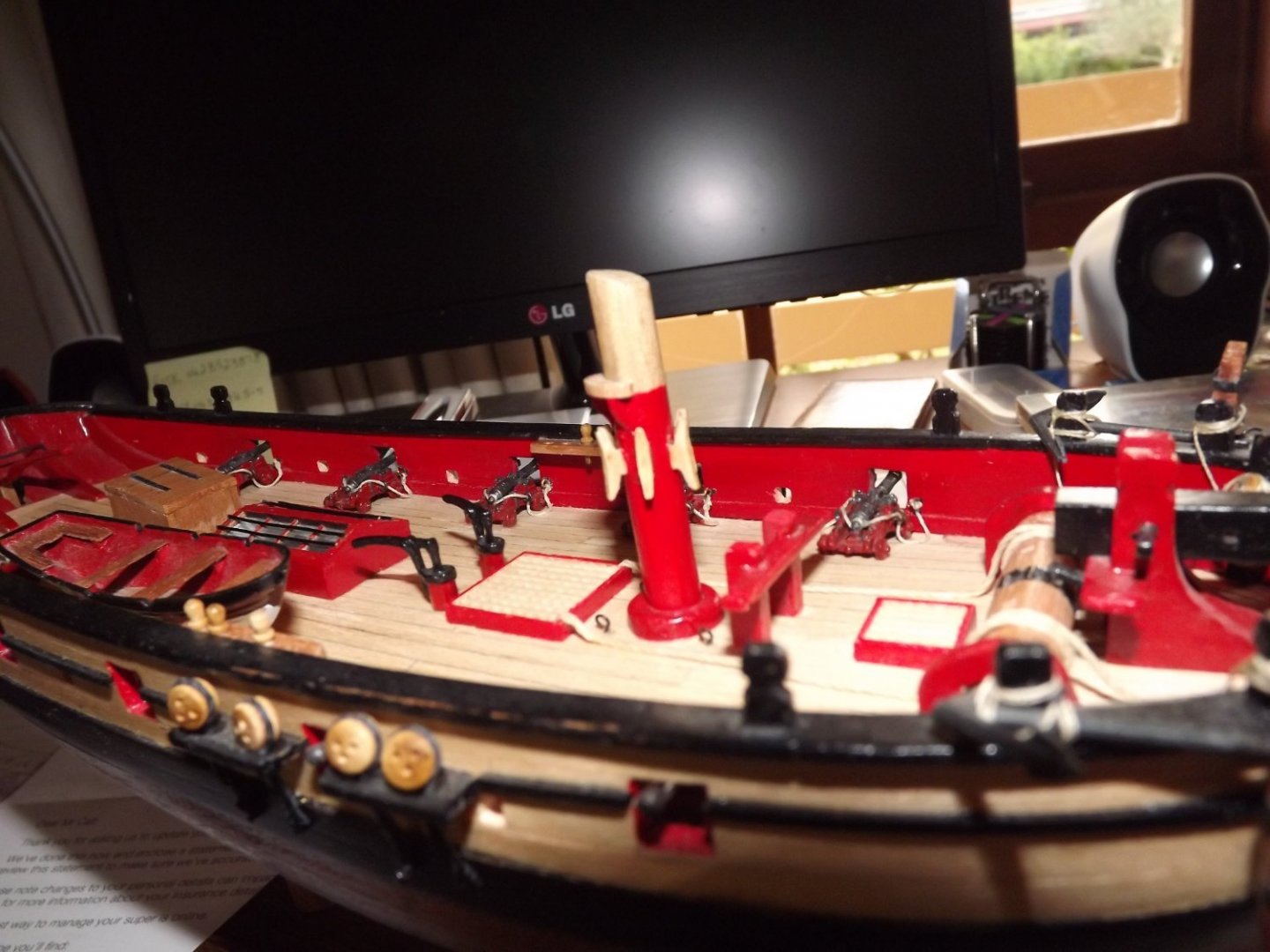
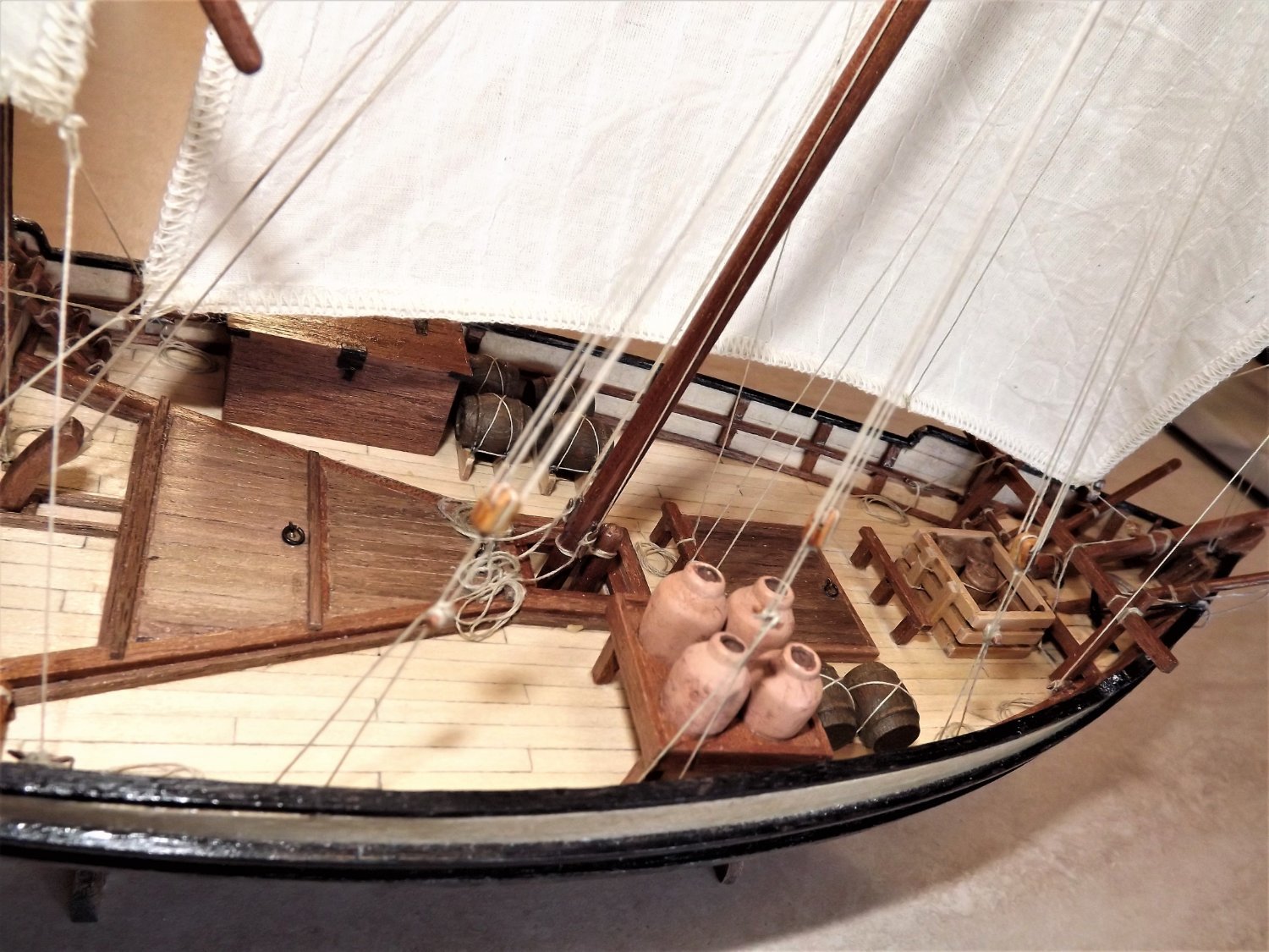
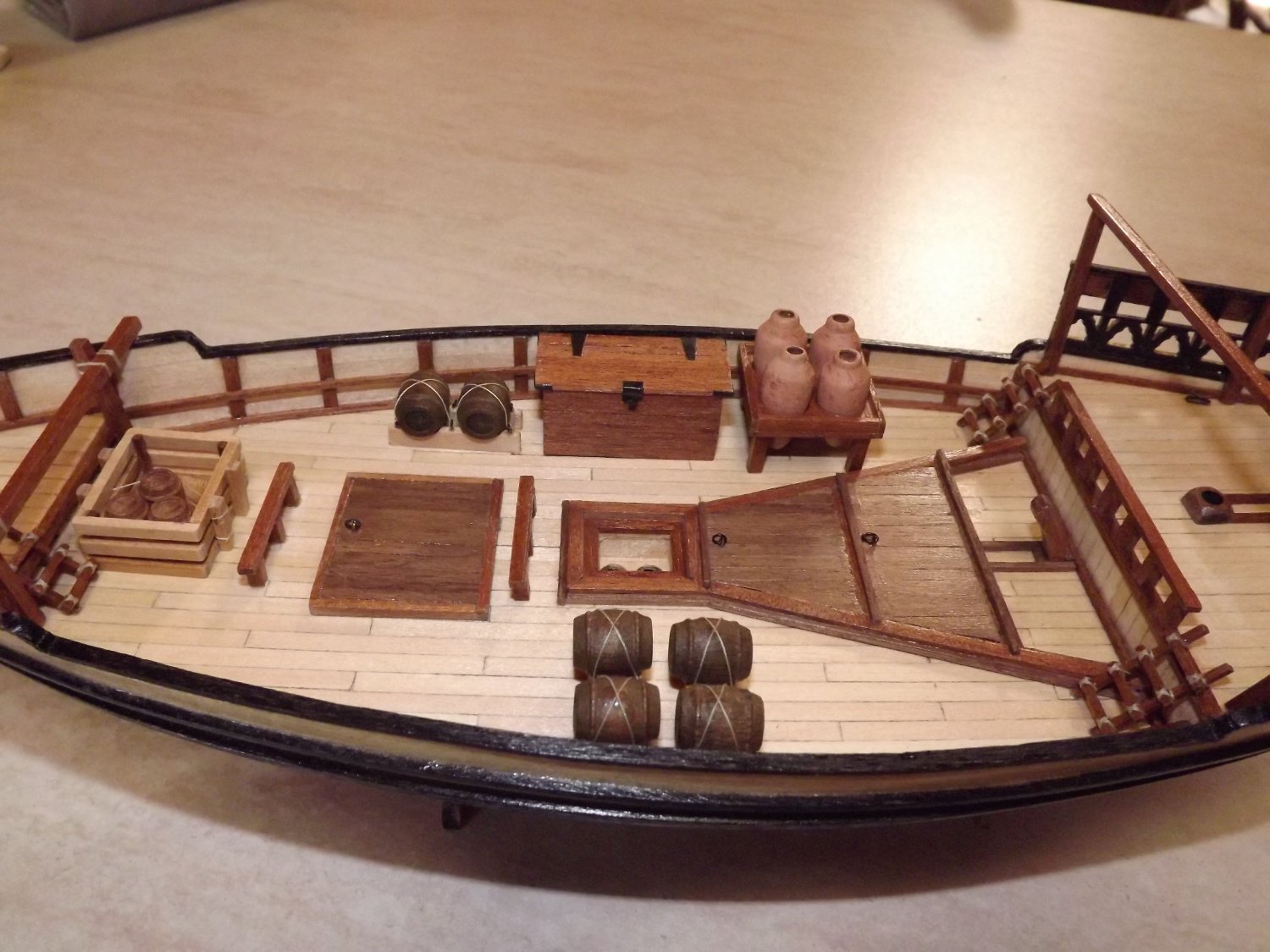
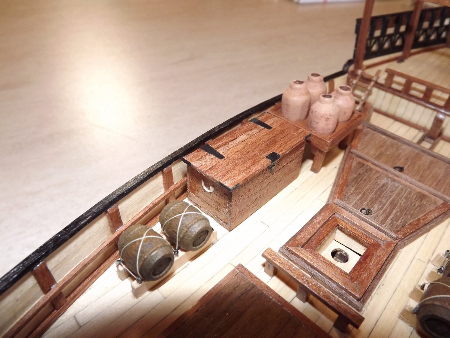
Main deck now finished, although there are a number of buckets to add at a later date. Personally I can't see that 1/2 dozen wooden buckets would be sitting loose on the deck so that will need some thought.
 I varied the hinges and latch on the chest using a heavy black cartridge paper instead of trying to blacken the brass they suggest. I also placed all three medium size barrels in the crate and put a lashing around them to secure them. Who leaves a barrel on its side to roll around the deck as the plans illustrate?
 Rick
Rick
-
Generally looking good, but the footropes on the main spar look a little "low" from this angle. Ideally they should be set so that man using them would be able to lean against the spar at waist height. So they should work out at a scale drop of around 85~90 cm approx. 14 mm +/- I think. I've always had problems with them myself and have found that to get a realistic hang to them a 50/50 solution of PVA glue and water will help set them properly.
Rick
- Keith Black and Gregory
-
2
-
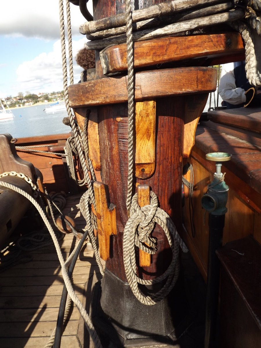
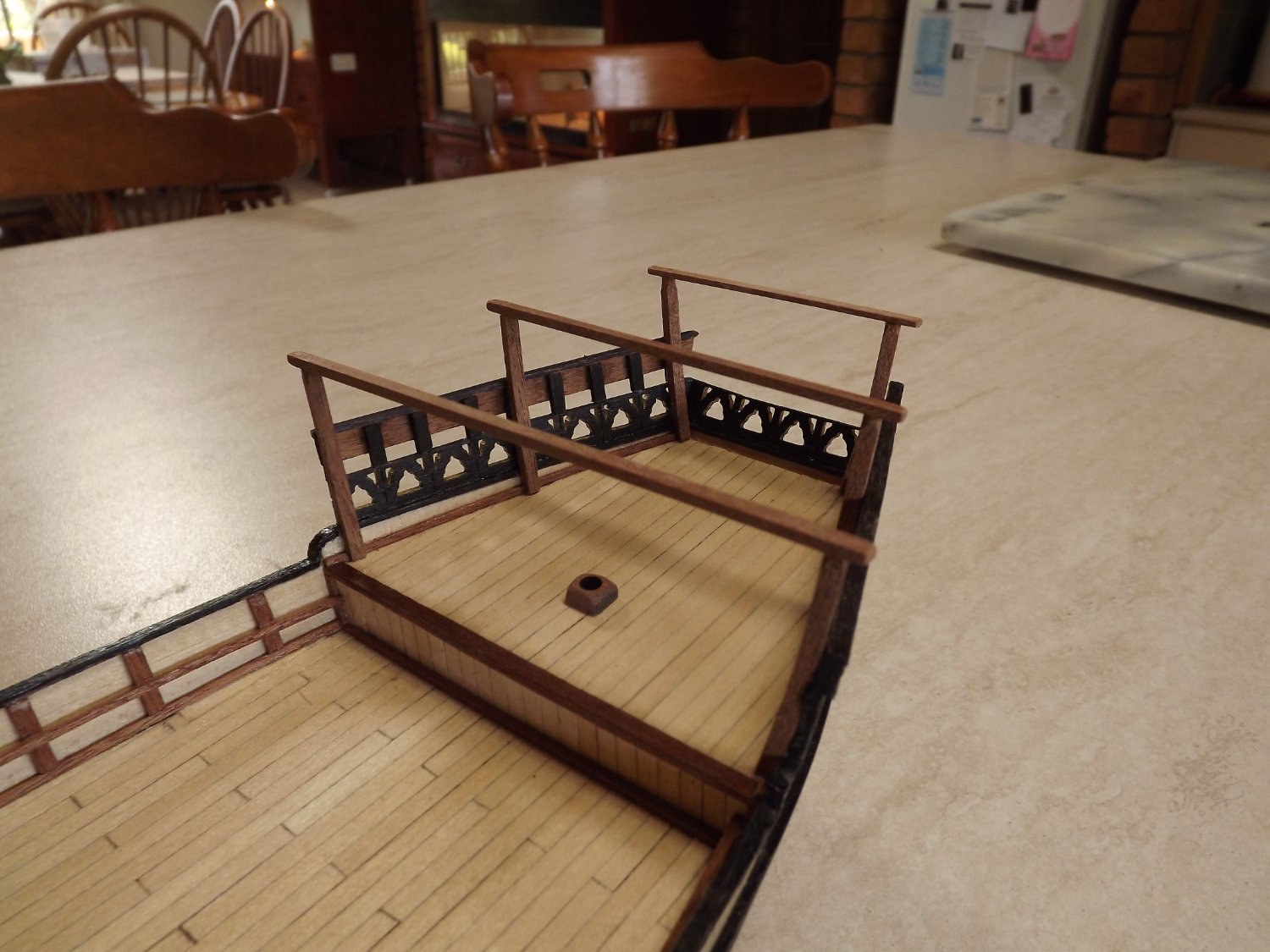
Whilst you've got reasonable access to the mast you may want to think about adding a rest to the mast for the yoke to sit on. This is how I've fitted one to s tripped down version of the Lady Nelson.

... and here's one on a replica of a similar period ship.

It'll make life easier when fitting the boom.
Rick
- bruce d, SUBaron and Keith Black
-
3
-
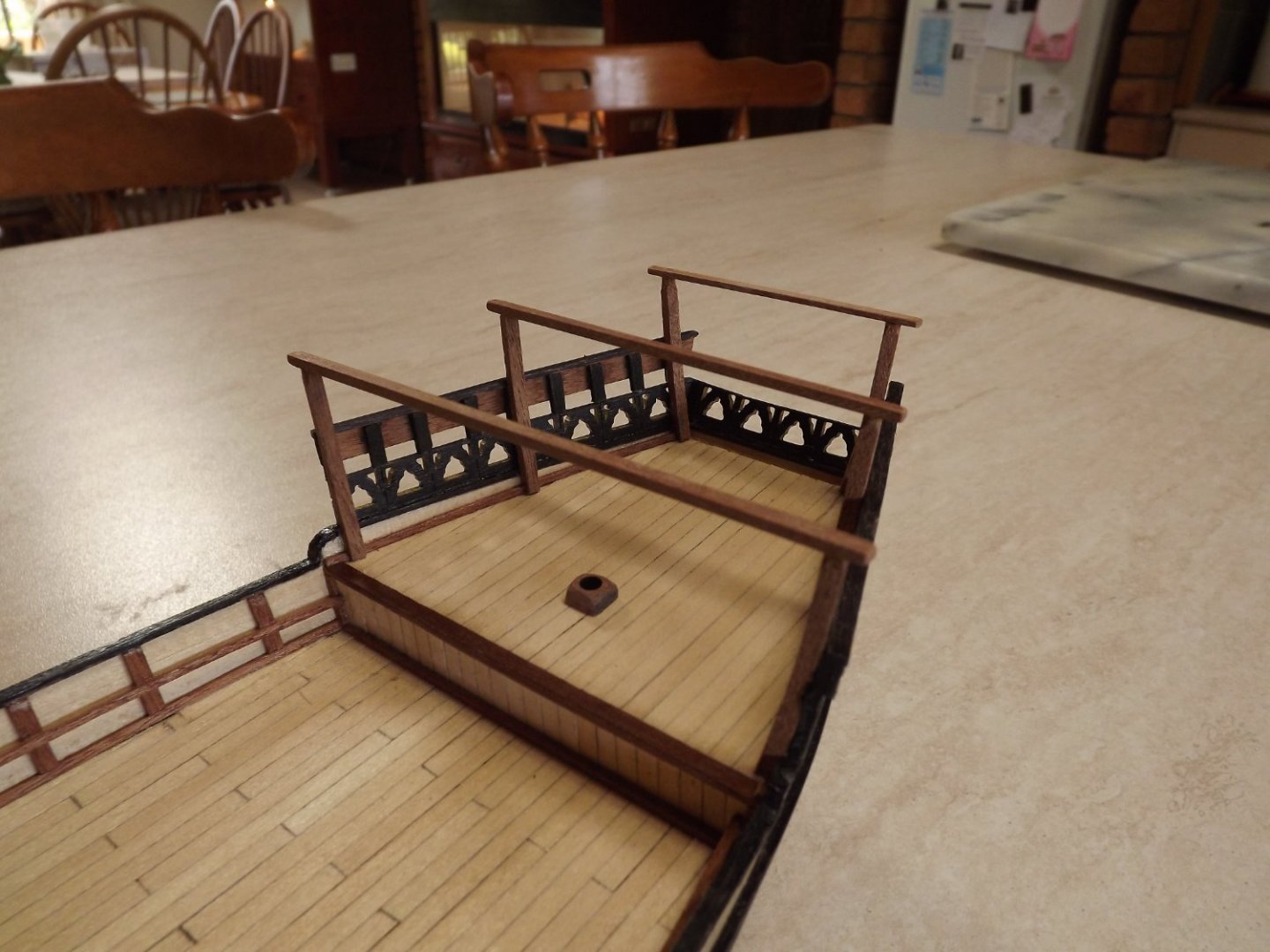
Hatch covers and a few other items now fitted, including the rudder, here I've used a stiff black paper to simulate the actual mounts. PVA glue then penetrates the paper, stiffening it further and attaches it securely to the hull. Interesting point here - I assembled the rudder/tiller exactly as shown, but when mounted the tip of the tiller is approximately 2 metres above deck level!! As the rudder is only resting in the mounts, it'll be easy to remove and shorten the post that the tiller sits on.

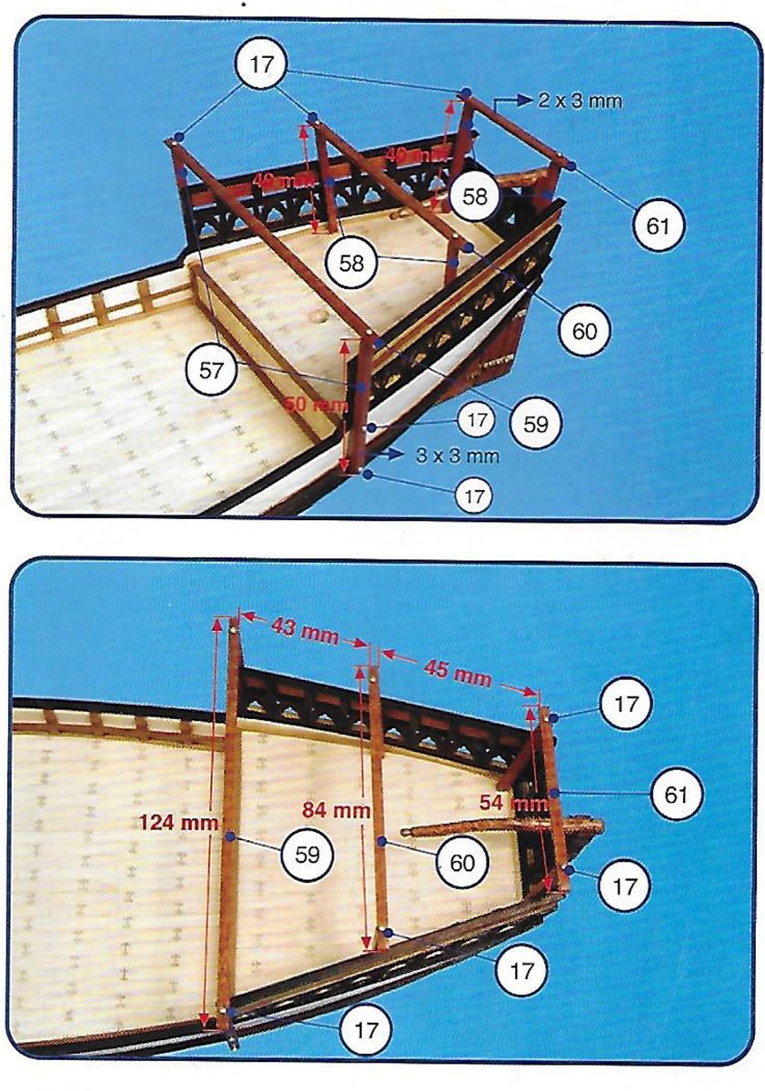
When fitting the transverse items (page 14 and 15) measure the actual widths on your model. I found that my gunwales were slightly wider than the sample used for the instructions, which necessitated making these "beams" longer.

Rick
- yvesvidal, ccoyle, Mirabell61 and 2 others
-
5
-
I don't see the cleats on the lower section of the mast, did you forget them? It can also be a bit of a pain fitting the boom and gaff as attaching the parrel beads to the yoke jaws will be a bit more fiddly. Standing rigging itself does look good.
Rick
-
May I suggest that you complete fitting the bowsprit, boom and driver gaff before fitting any rigging. You'll find it much easier than trying to work round any existing rigging, particularly the boom and gaff. I have built this model although I don't have the build on this site.
Rick
- Gregory, Keith Black and Dave_E
-
3
-
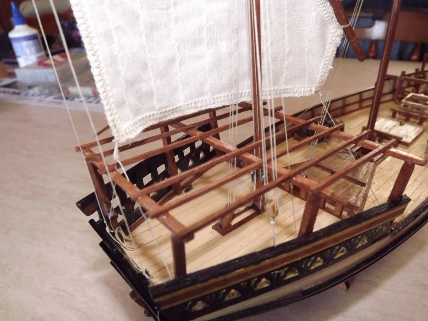
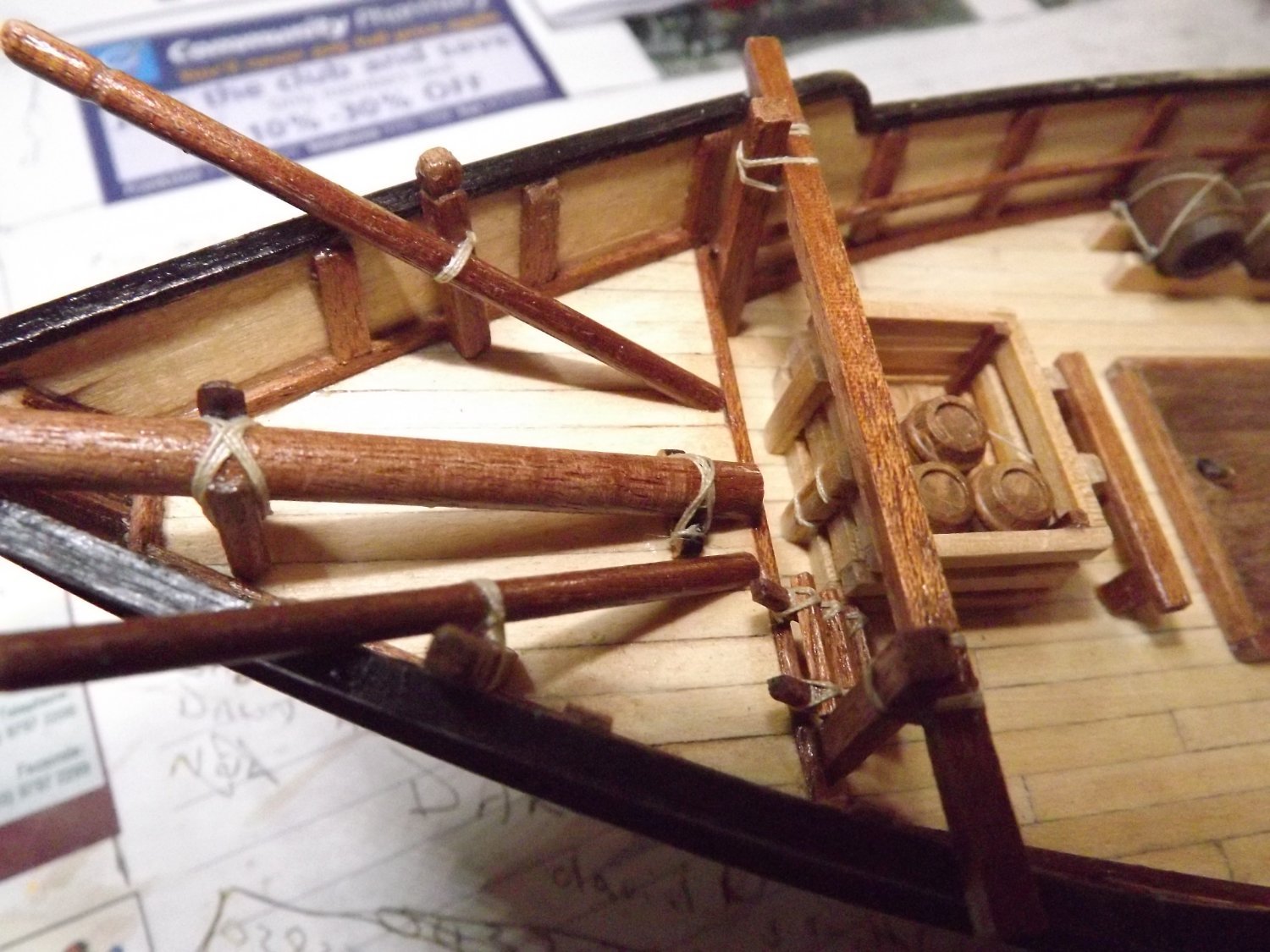
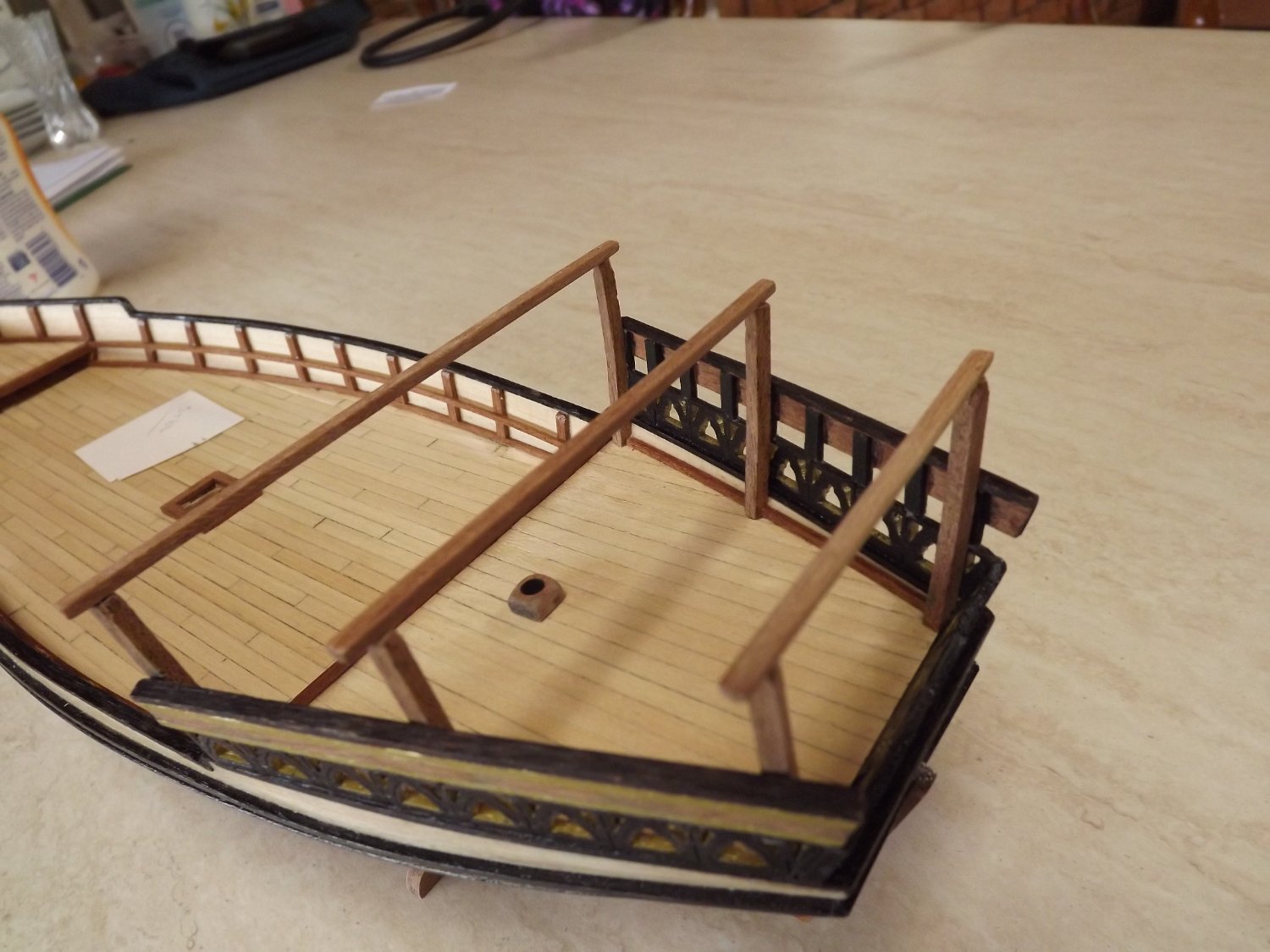
Some deck furnishings fitted now.
You'll see that shall cleats have been added to the deck and the back upright. According to the instructions these are not added until page 28 of the manual. However as you can see, at that point the deck is pretty crowded and fitting them would be a pain.
On page 21 you are instructed to assemble 3 ladders of equal size.
Here's what happens to the 3rd ladder.

Pretty obviously it should only be 3 rungs high, in my case I'll have to cut it down as I can't see that a ladder of that height is correct.
Finishing the deck furniture is the next job, but It'll take a while as I do have a few other things I'm involved in.
Rick
- GrandpaPhil, yvesvidal, clearway and 2 others
-
5
-
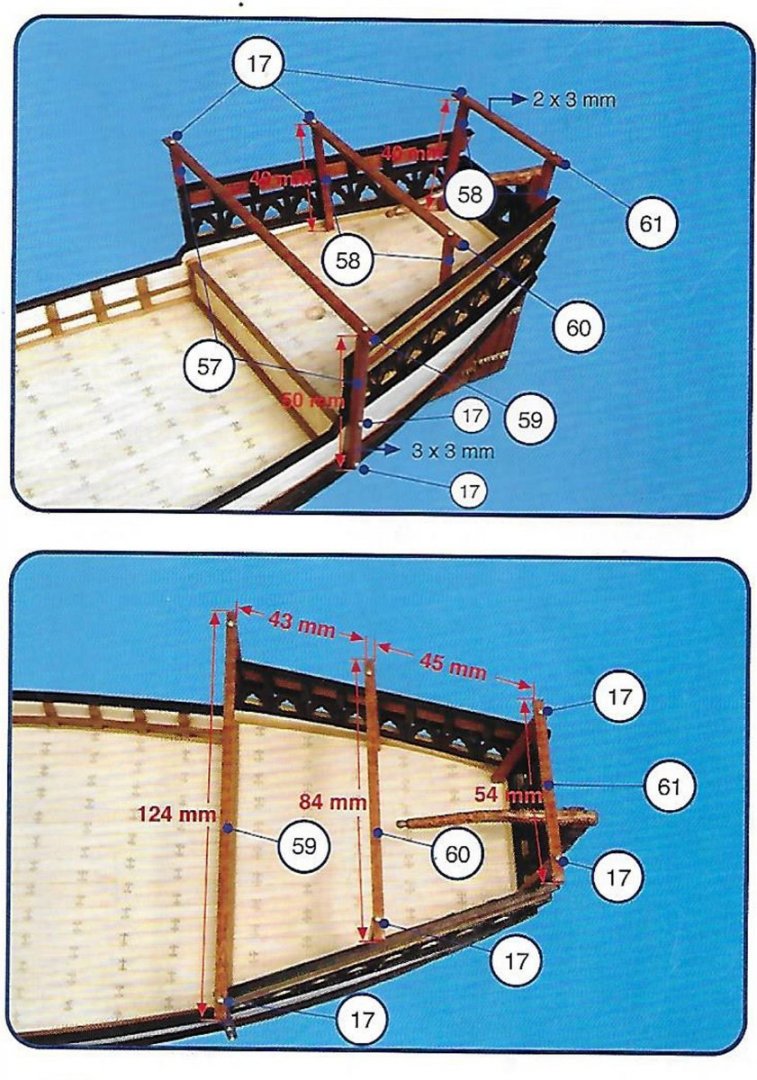
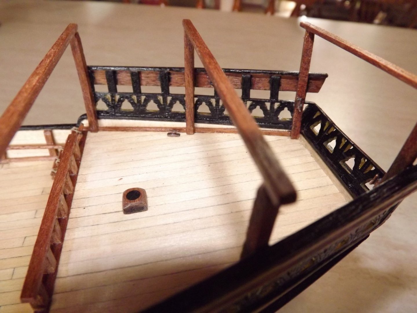
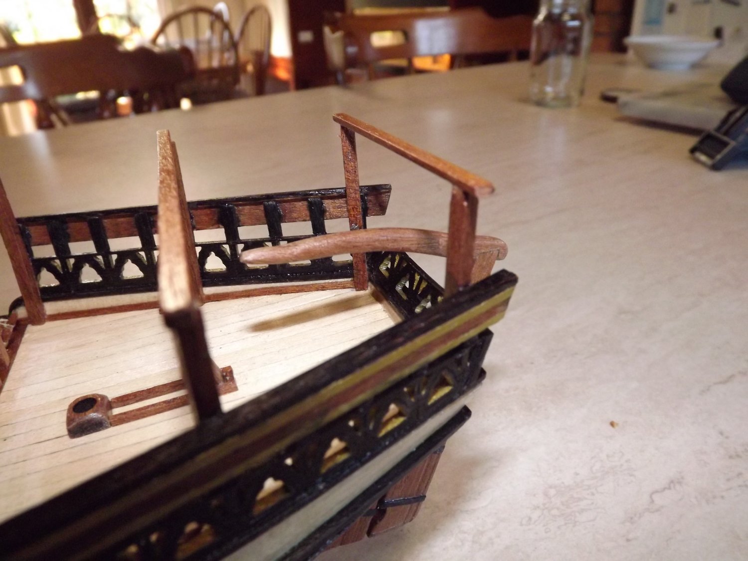
I've got a little further and now have the aft structure holding the canopy half finished.
I started with the decision to site the first upright inboard rather than outboard as shown in the plans. I've been unable to find any photos showing this method of construction and it doesn't make sense to hand an upright off the bumper strips.
I first made a template to match the curve of the fretwork, then assembled a jig from scrap MDF to match the template. Six lengths were then cut and soaked for 24 hours before clamping in the jig for a similar time.
I forgot to photograph the template before assembly but this does show how I did it. As the deck slopes upward the pencil marks on the template indicate where the curve stops an the upright changes to a straight piece (hope that makes sense)
.

Once they had dried, it was just a matter of matching them to the upright sections of the fretwork and gluing.

Next was the cross pieces. I would suggest that you don't cut them to length until you've checked that the spacing across the uprights corresponds to that shown on the plans. I just measured each pair, added 8 mm (4 mm overlap each side) and the glued rather than tried drilling as I'm not known for great accuracy with a drill. This then is the end result.
Rick
- GrandpaPhil, CiscoH, yvesvidal and 1 other
-
4
-
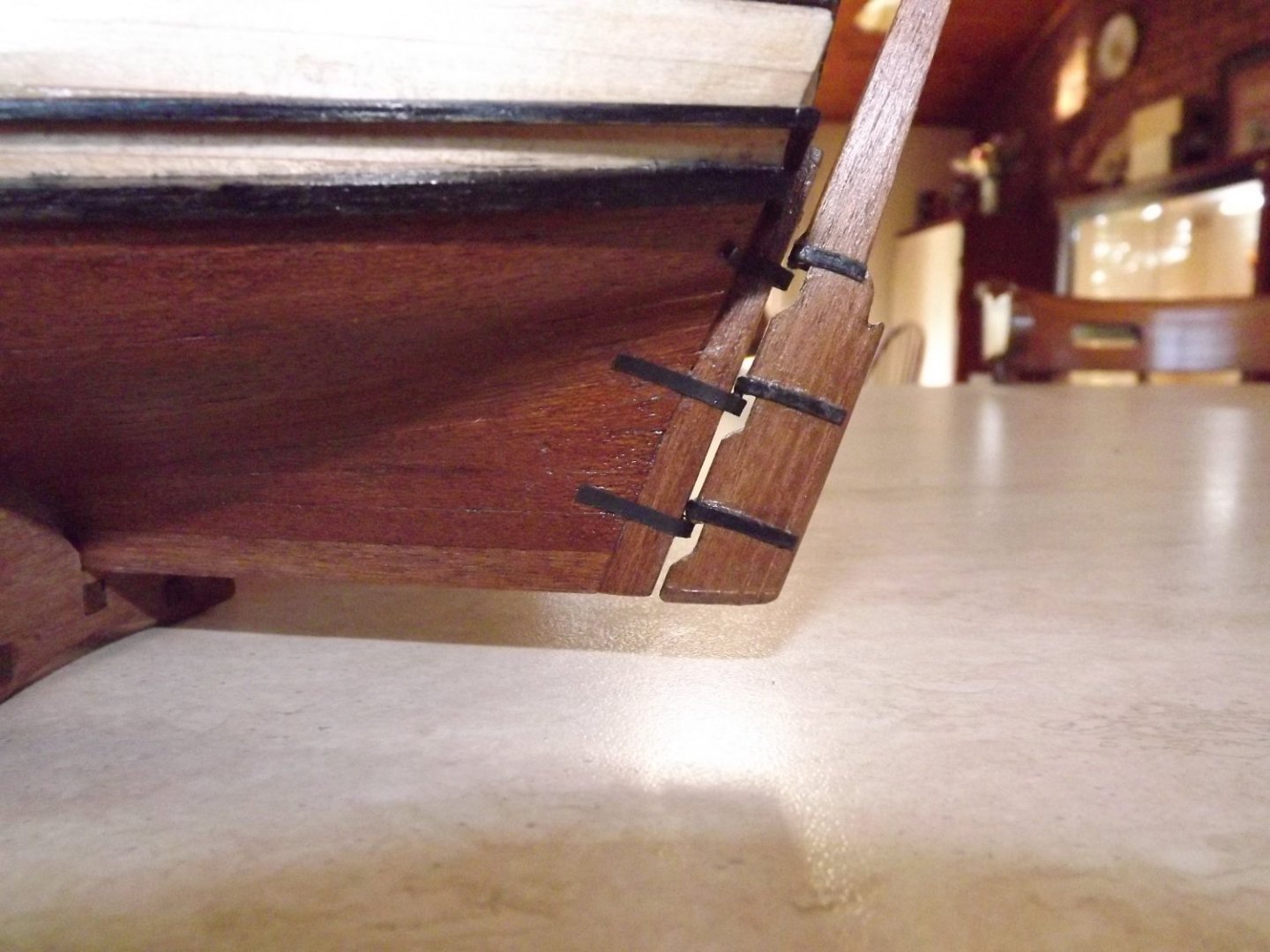
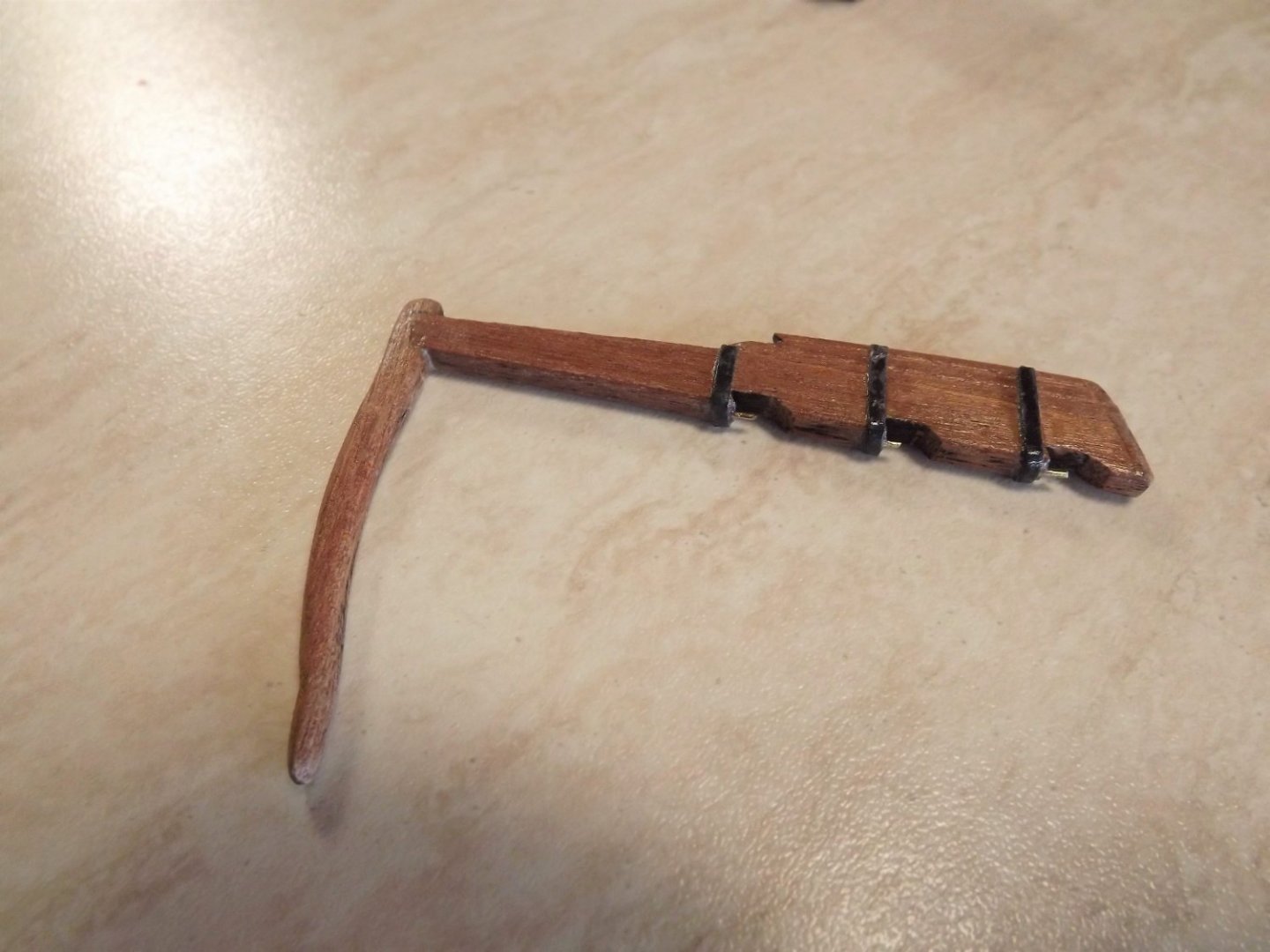
With a few other things to be completed around the house I'll be giving the ship a rest for a short while. However I have sorted out the rudder, again varying how I've treated it compared to the instructions. Firstly I tapered it slightly as it did seem to be a rather ugly and over thick plank.
Then instead of the brass (as I didn't have any brass blackener around) I used black cartridge paper soaked in PVA glue to form the retainers for the rudder pins. As for the pins themselves, my hands aren't steady enough to effect the drill holes they recommend, I made grooves in the rudder, set pins in the grooves and glued the retainers over them to hold the whole assembly in place. I haven't added imitation bolts as I don't feel that they realistically would be visible at this scale.
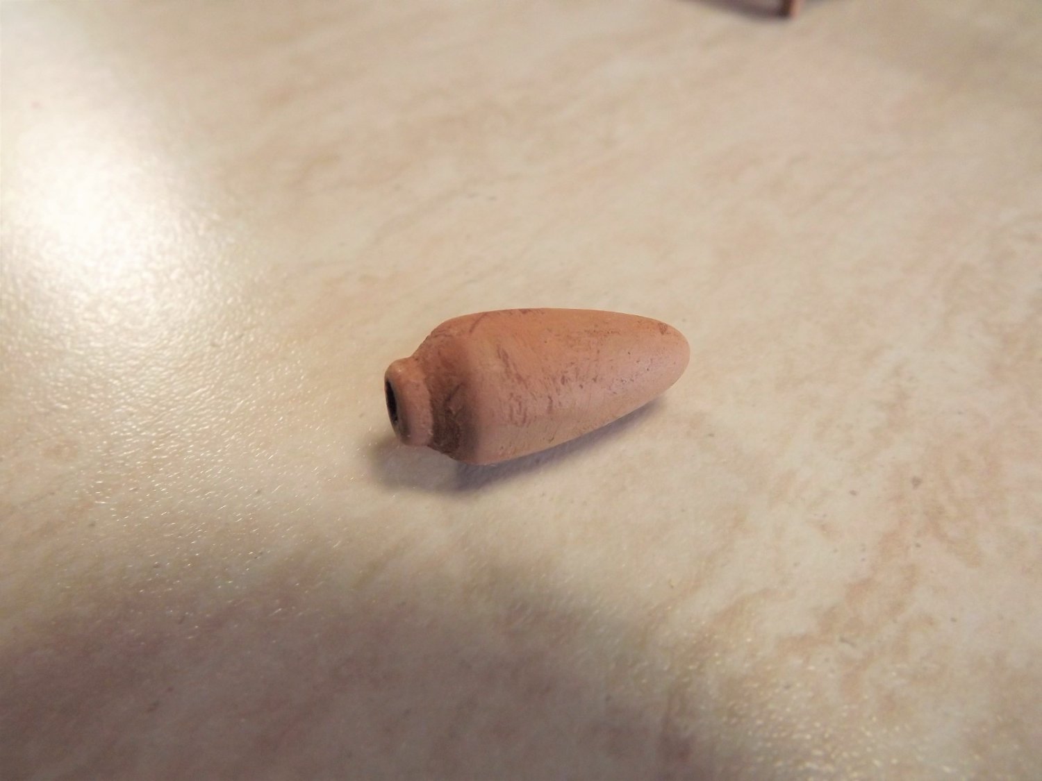
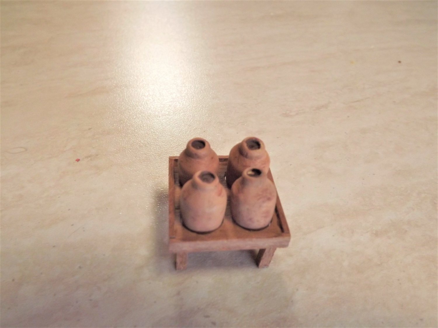
With the oil/wine jars, again the instructions leave them as unpainted wood (looks pretty bad to me). I've used a mix of Tamiya Acrylic flat paint XF-68 Nato Brown and XF-15 Flat Flesh, with the flesh as the base colour and then adding the brown until I had a terracotta effect that I was happy with. Finished off with a VERY light brush of brown to weather them. The holes in the rack holding them will need careful enlarging to have the jars sitting reasonably well and getting the legs perpendicular was fun!


Rick
-
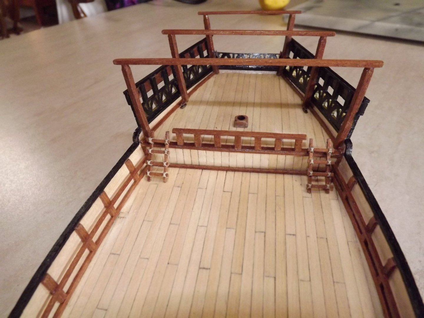
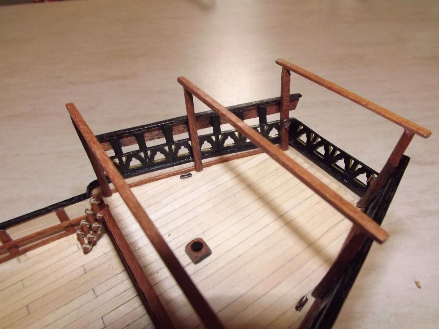
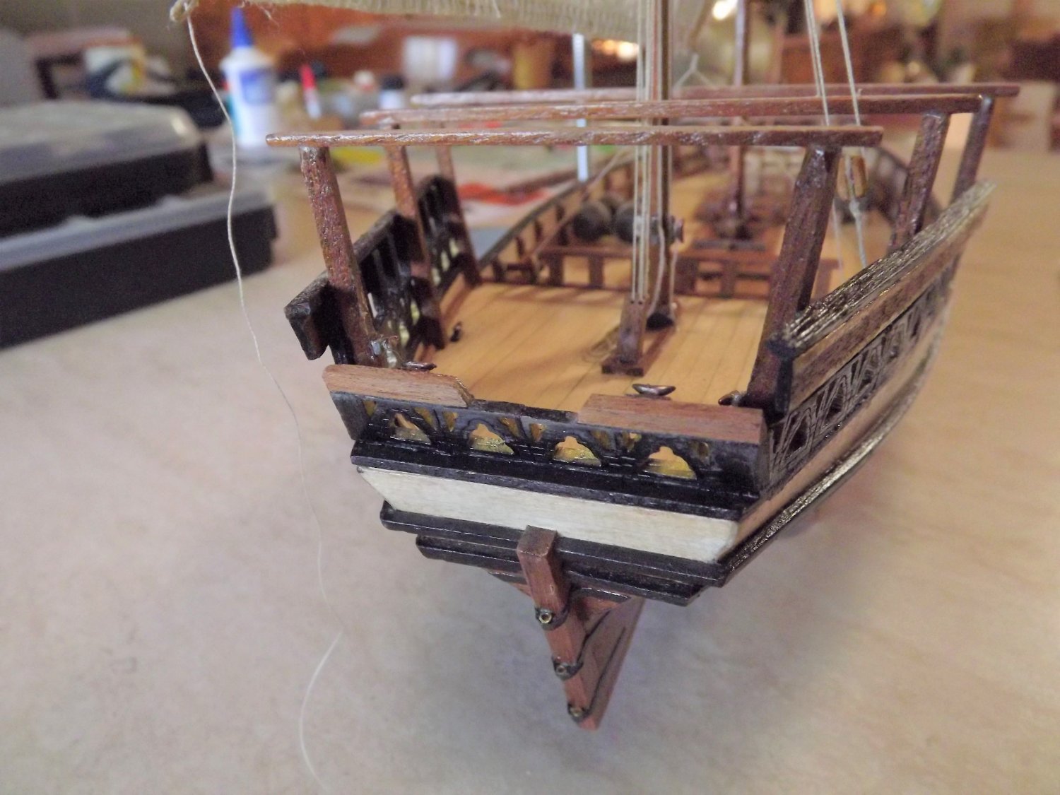
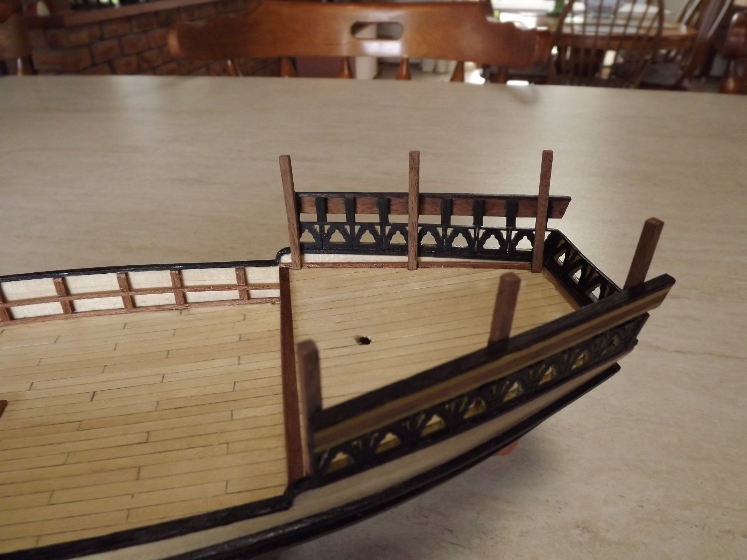
I've now completed the decorative work on the stern area, The lower fretwork is very fragile and snaps as soon as look at it, one section has around four repairs in it. Fitting to the bulwarks is not the easiest as it requires a slight curve to match the profile but of course has to be very carefully coaxed into position. The upper decorative panel is slightly easier in that you should curve it and its capping rail to match thee run of the bulwarks before attempting to mount it.
You'll notice that according to these instructions the uprights on the top panel don't match the similar "ends" of the lower fretwork. To me this doesn't look correct so with mine I spaced the uprights to match the lower assembly (see below).
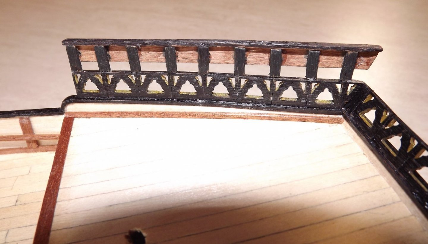
Close-up photos really make the work look rough!!
Rick
-
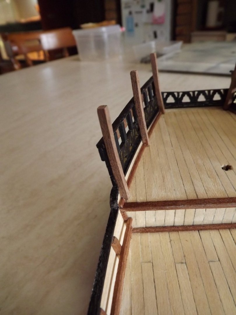
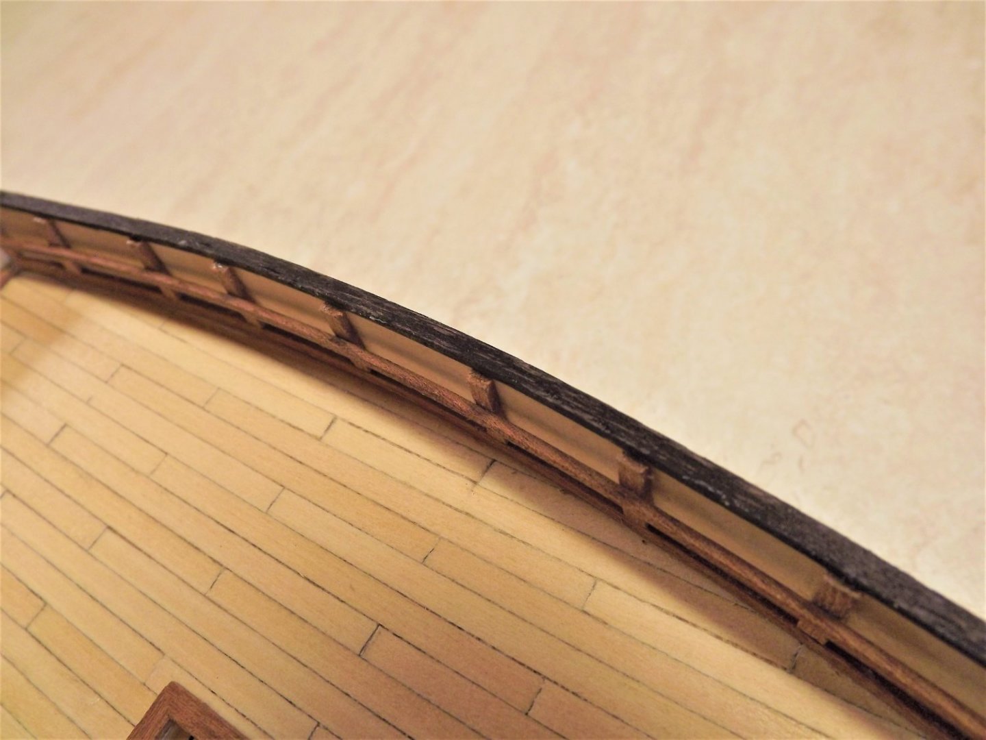
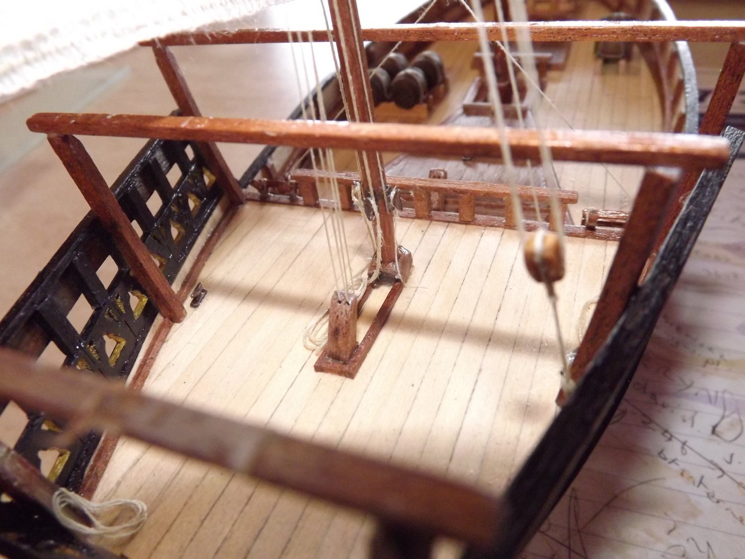
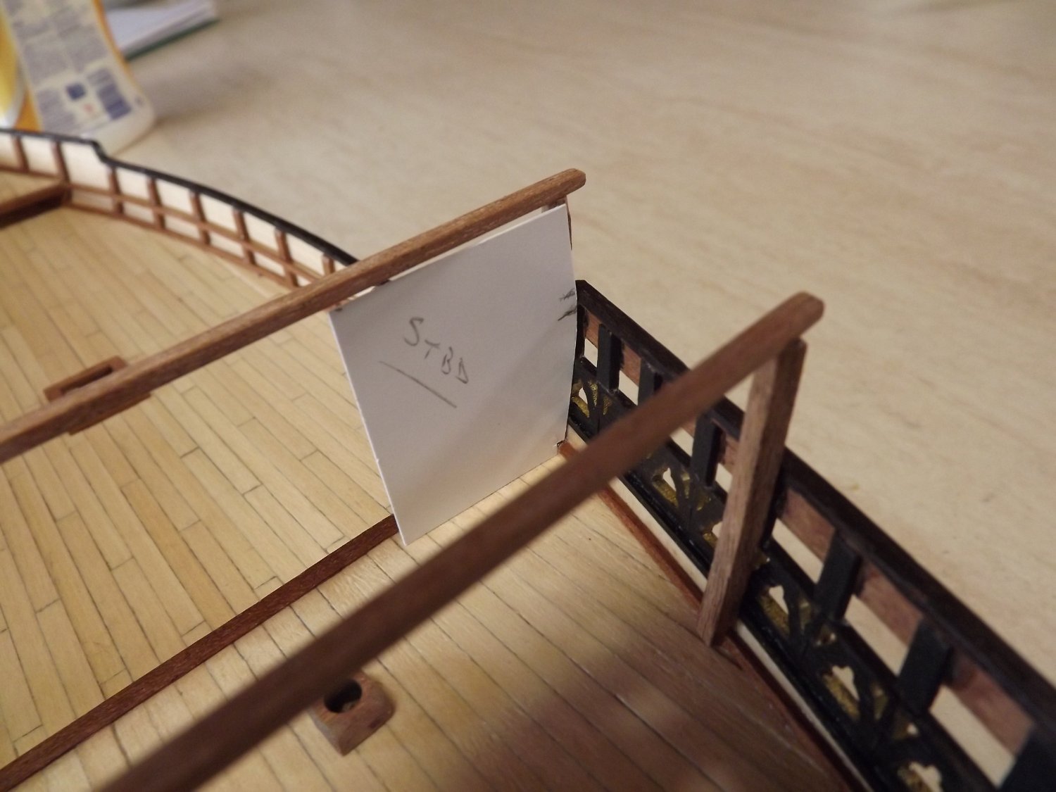
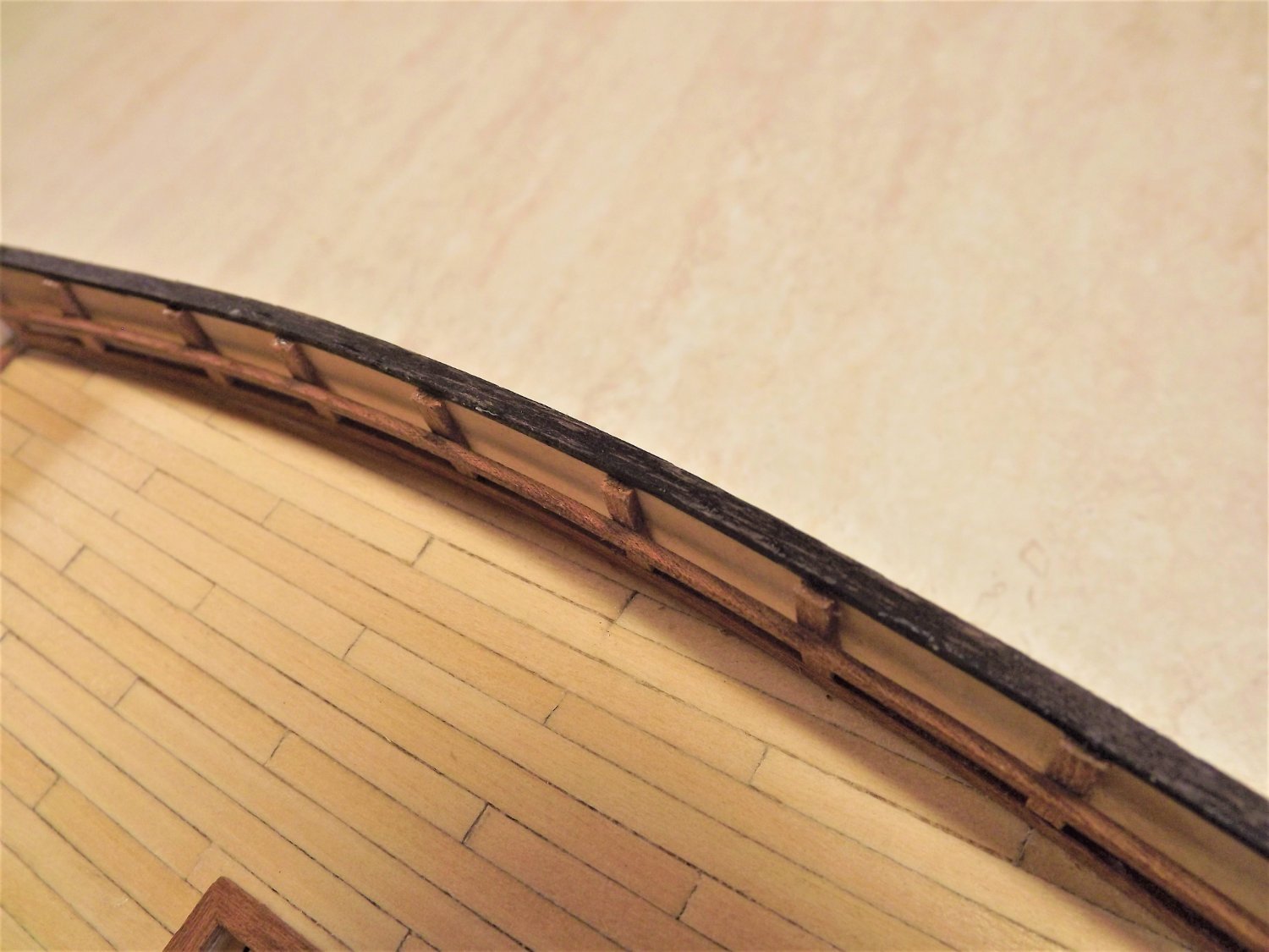
Staunchions fitted as per instructions.

One error here however. I should have spotted it and possibly the instructions should have mentioned it. The gunwales thickness is approximately 4.2 mm whilst the cap rail is only 3 mm! Searching further in the instructions, I found a photo that shows the top of the staunchions as having been beveled back to the edge of the cap rail. So some careful sanding back will now be needed.
Rick
-
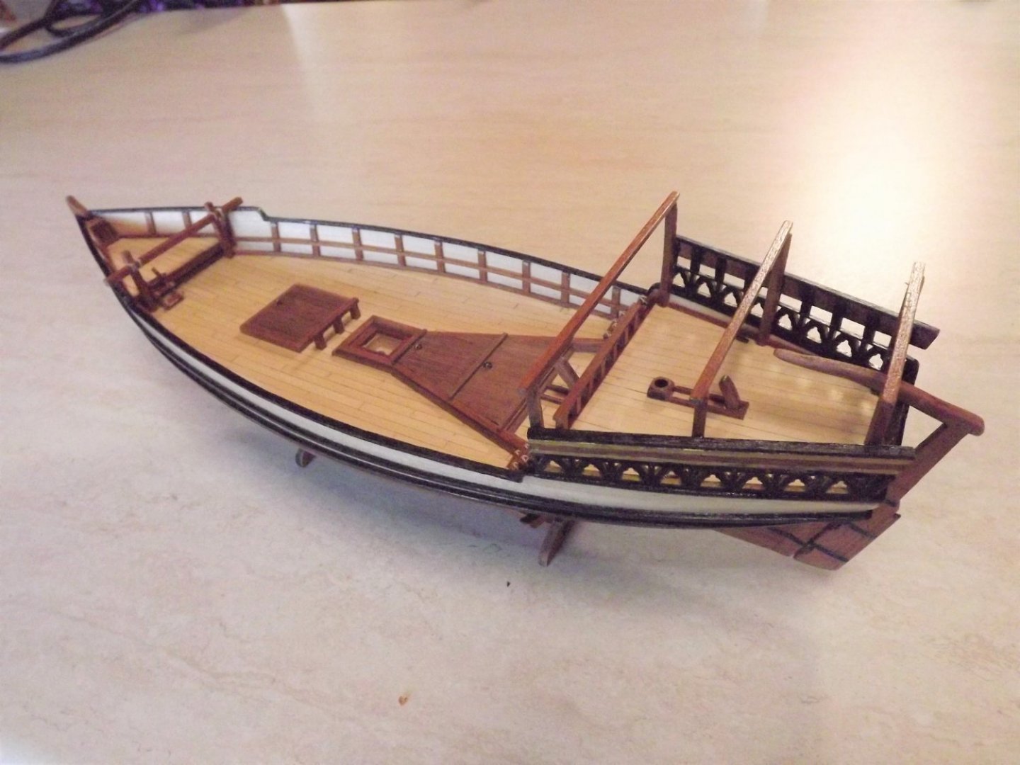
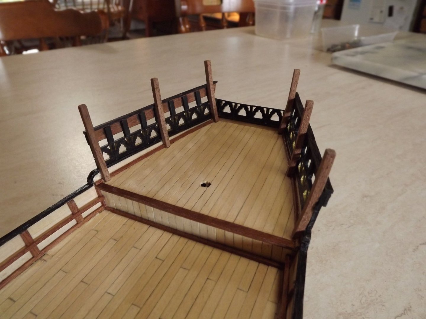
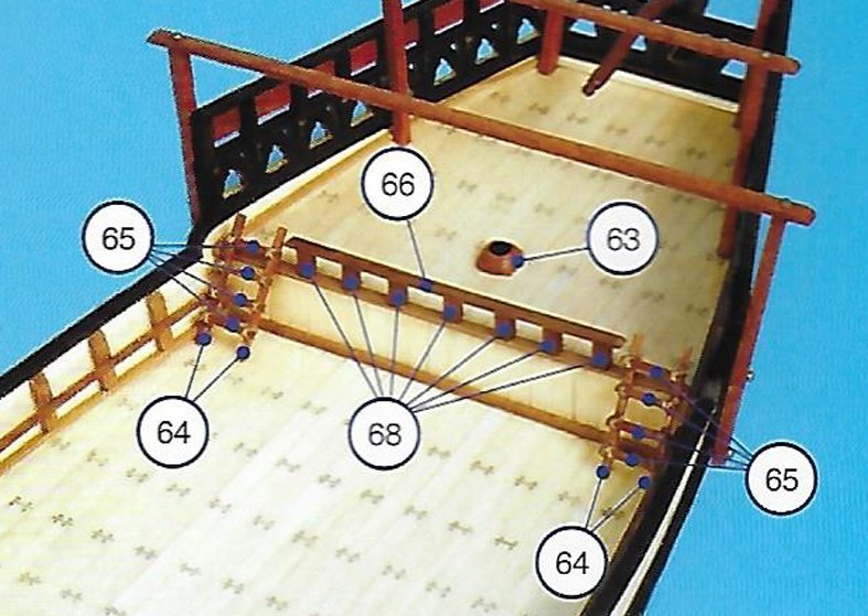
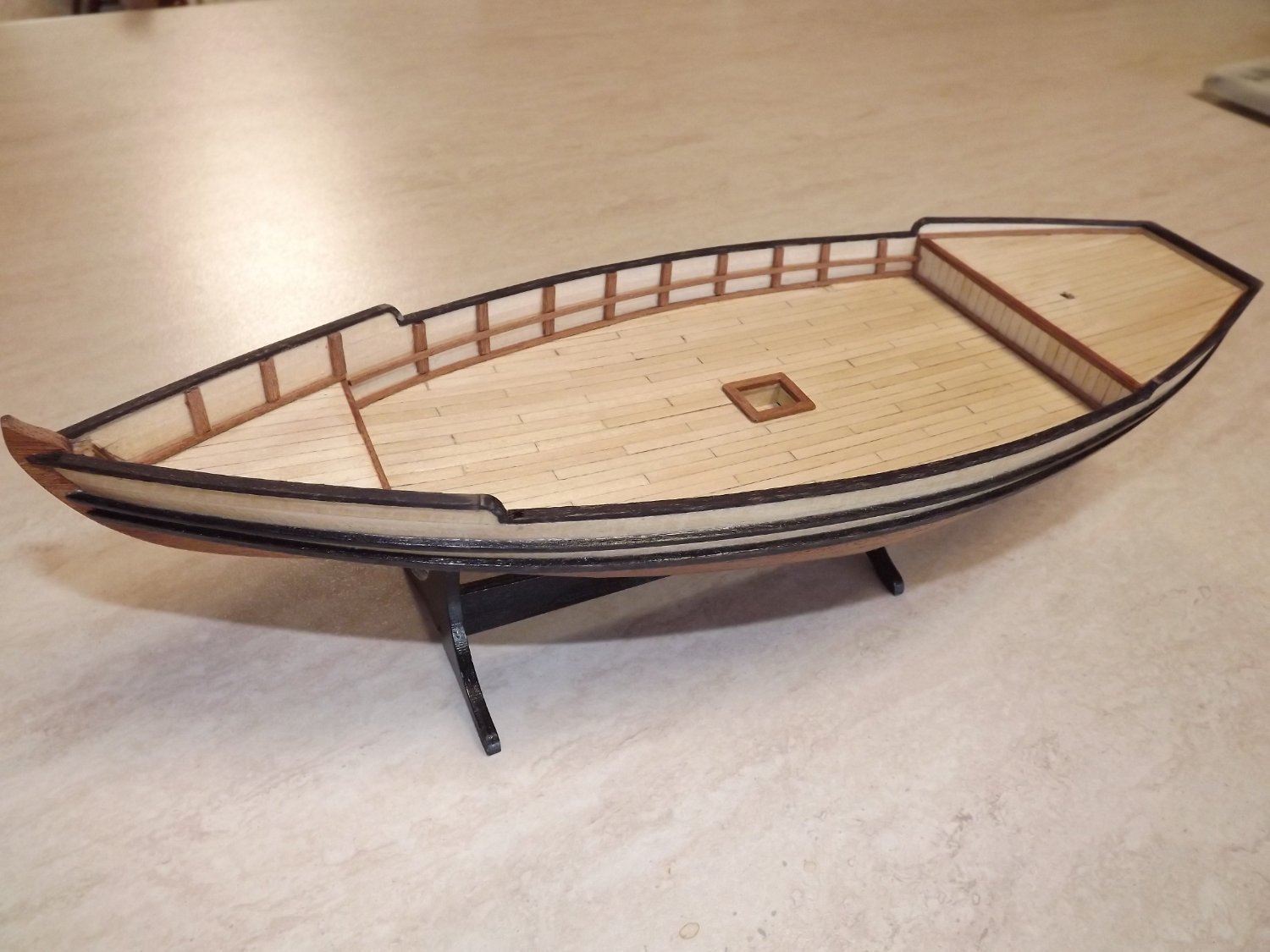
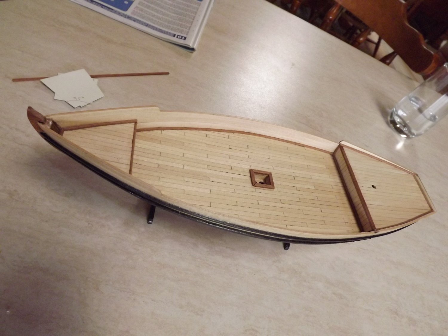
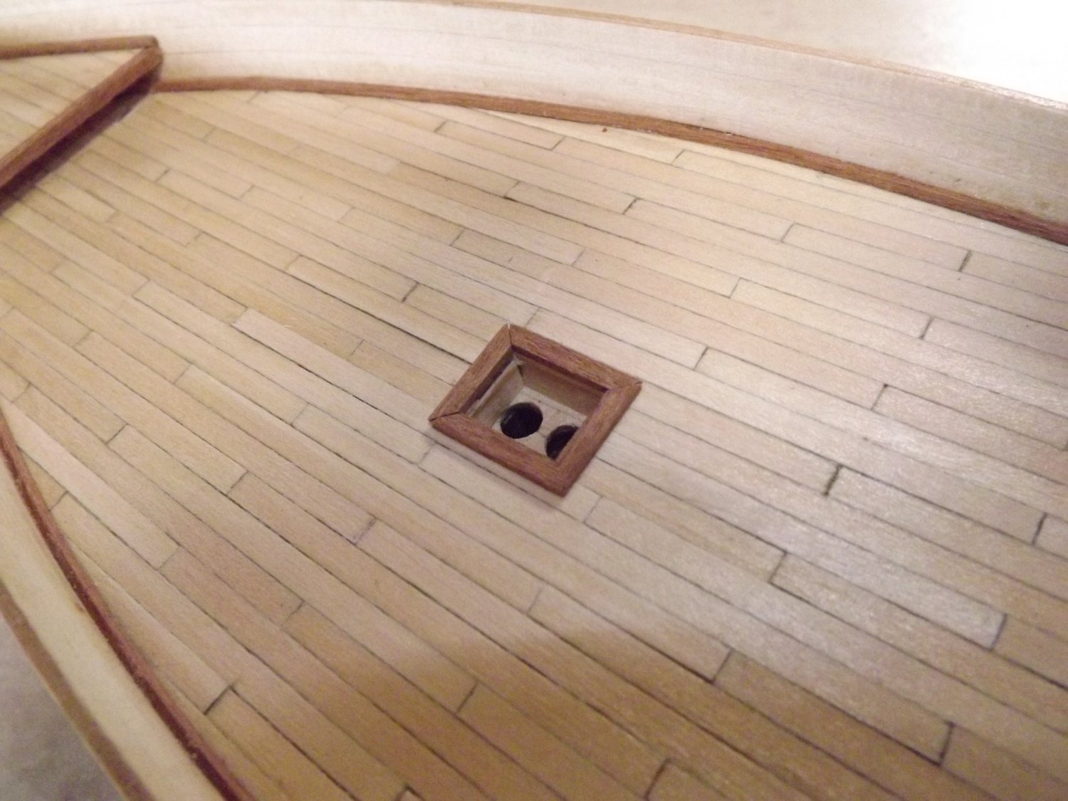
Now has the trim added on the decks to finish off the decking.
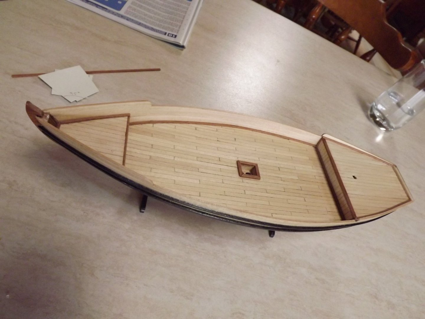
This is where the need to read ahead seems to happen. The trim on the aft deck is 1.5 mm x 1.5 mm but reading ahead to page 21, there is a "fence" installed across the aft deck sitting on the trim. The uprights (part 68) being 3 mm x 3 mm, this would mean that these would be half on, half off this trim section. This really didn't make sense to me so I've placed a 3 mm x .6 mm length over the existing trim (I'd already fitted the 1.5 mm x 1.5 mm and wasn't going to attempt to remove it).
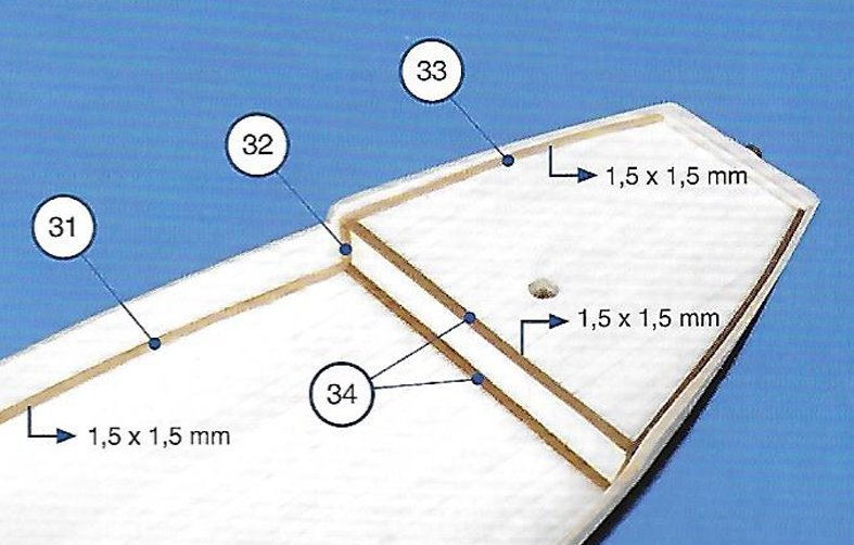
Then the edging around the "small deck" in which the main mast sits is very tight and requires a support post angled back at 88 deg. in the forward hole which braces the main mast.
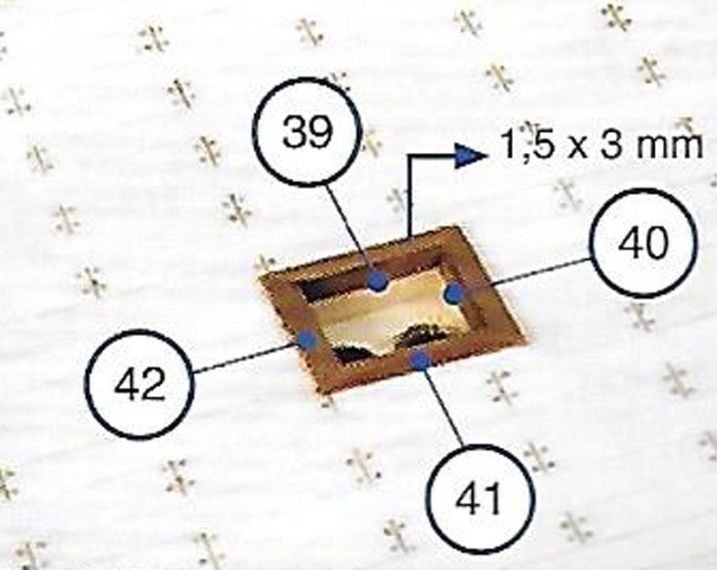
This shows that the inner edges are to have a 1.5 mm x 3 mm insert, but as can be seen here the tolerances are very fine even without the insert.

I've chosen to ignore parts 39 & 40, only fitting 41 & 42 as the tolerance was to fine for me to get the correct angle on the brace.
Next step will be to again read through the instructions and to try and anticipate any more of these little hiccups.
Rick
- GrandpaPhil, yvesvidal, clearway and 1 other
-
4
-
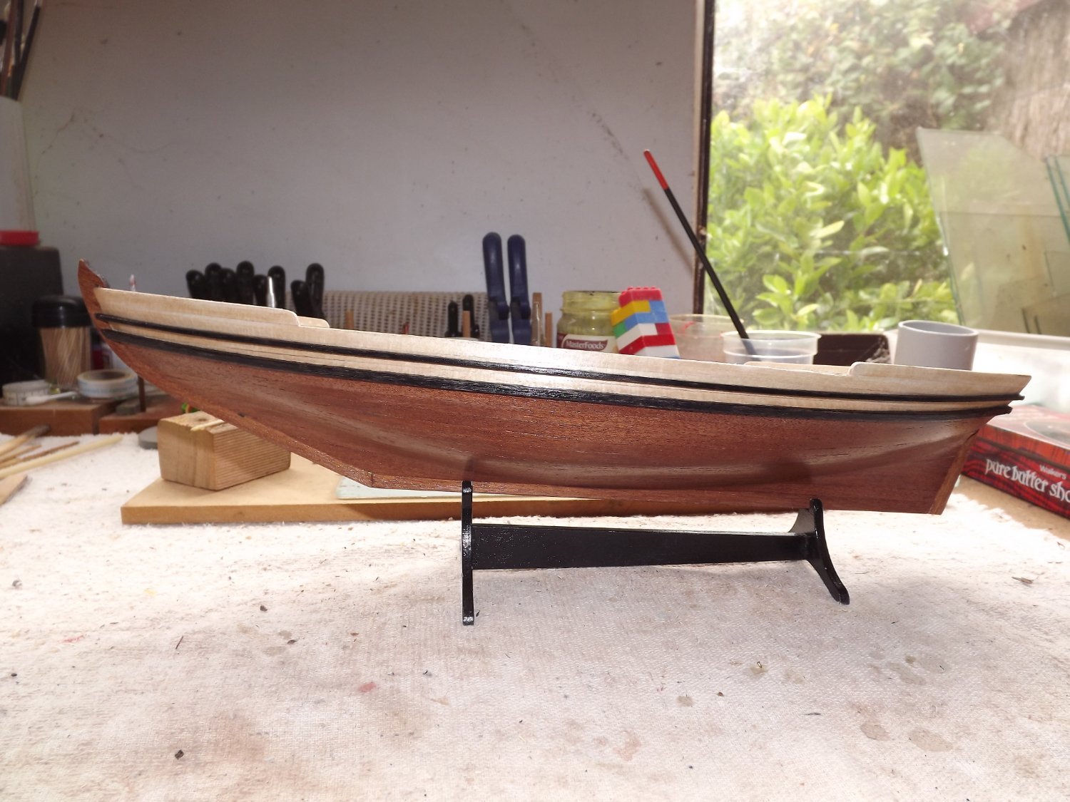
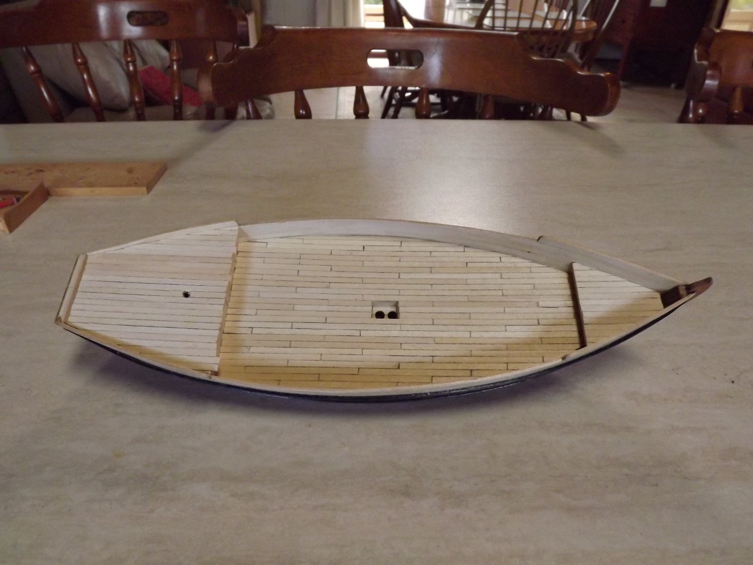
Well I've now fitted the fenders after staining contrary to the instructions. The plan calls for a 4mm gap between them, this was easiest done by temporarily fitting a 4mm wide strip of planking between the two fenders (left over from another job), then removing once everything was dry.

Decking next. Here I decked both fore and aft decks with single length planks as the maximum length appeared to be 15 ft (assuming the plans are somewhere near correct 😉 ), for the main deck I used 12 ft scale lengths rather than the 6 ft the suggest as this really didn't make sense to me. These were individually cut and laid rather than lay full length then mark off with pencil as recommended. Done their way the deck looked to perfect, manually it has a bit of variance with colour etc.

The deck will now need sanding and I'll add a single coat of a satin finish water based varnish to protect the surface before the next step. Obviously I still need to tidy this up before moving on to adding various bits of "trim".
Rick


.jpg.a3f5e984f168086b9d60fe9f72b70aad.jpg)
.jpg.6984430c548b2002f6658415345071a7.jpg)


Sultan by Rick01 - FINISHED - Artesania Latina - 1/60 - Arab Dhow
in - Kit build logs for subjects built from 1901 - Present Day
Posted
Did that at the same time as posting these photos. 😉 Thanks for following, I wonder, if I'd put a couple cannon on it and built it as an 18th century dhow, would it have gained a little more attention?
I do have another couple of builds under my belt, but they didn't make it here, now to decide what next.
Rick