KeithAug
-
Posts
3,986 -
Joined
-
Last visited
Content Type
Profiles
Forums
Gallery
Events
Everything posted by KeithAug
-
 Julie The shaping of the assembly only took about 10 minutes. Sanding the individual block took about the same time once it was parted off. Thanks to everyone who hit the like button.
 -
John Thank you. I think I am going to have to intersperse block making with other tasks, I can't face up to the prospect of banging them all out one after the other. Much too tedious. I haven't counted up how many I need lest it drives me to despair. I will save the count for when I am in a good mood.
-
ancre La Salamandre by tadheus - 1:24
KeithAug replied to tadheus's topic in - Build logs for subjects built 1751 - 1800
Pawel They all look very good. Keith -
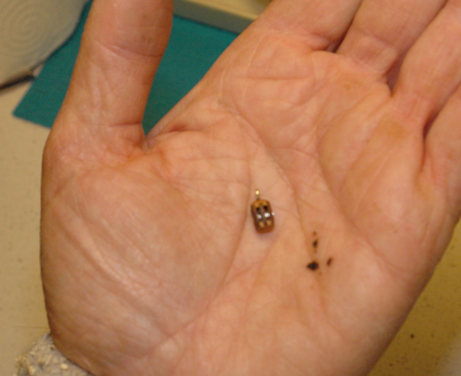
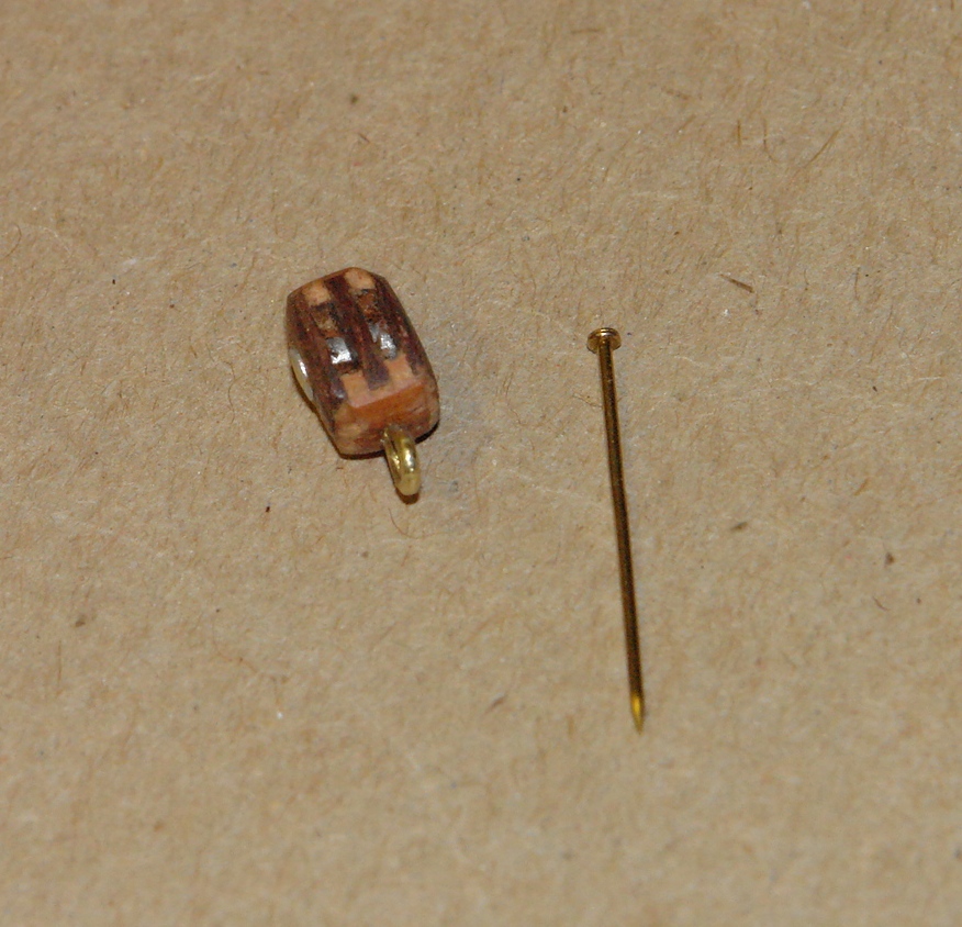
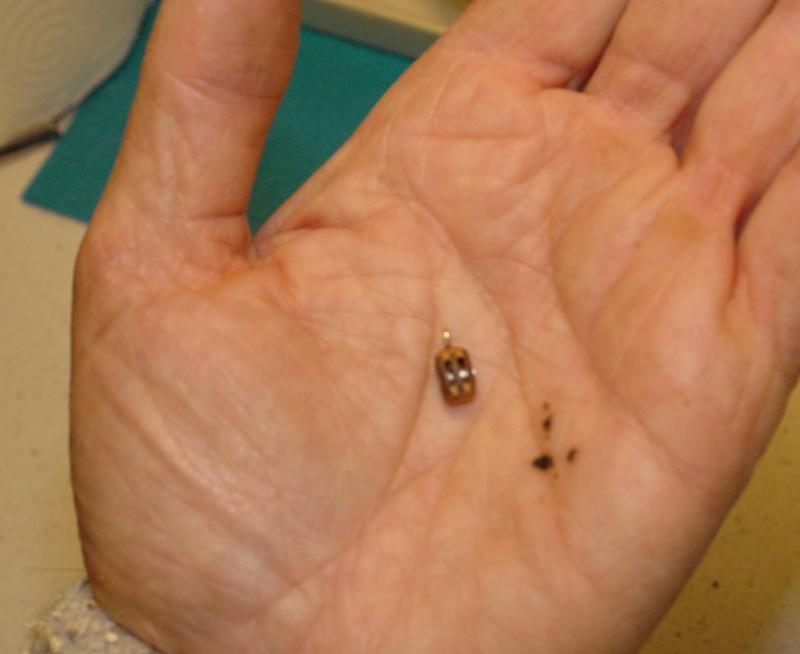
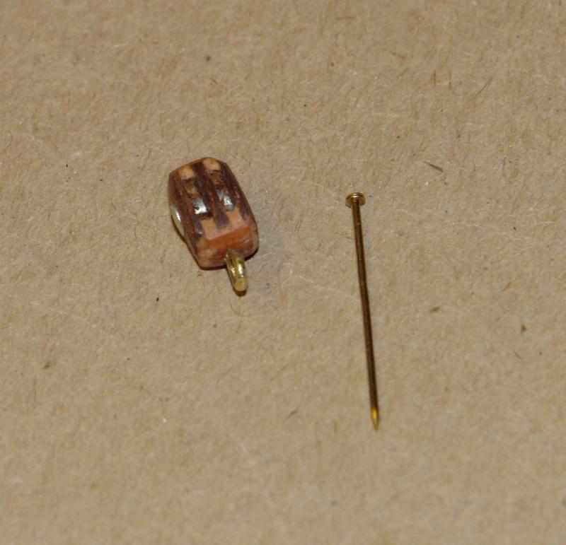
Today I spent much of the time cutting 3" x 2" x 8 foot lengths of timber to repair the lounge floor. As a reward I finished a 2 pulley block. In terms of size it was a case of the ridiculous to the sublime!!!!! The pin is a standard 20mm dressmakers pin.
- 882 replies
-
- 11
-

-
ancre La Salamandre by tadheus - 1:24
KeithAug replied to tadheus's topic in - Build logs for subjects built 1751 - 1800
Pawel What are the barrels made from, they look like metal but the white one suggests something else? -
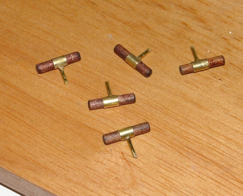
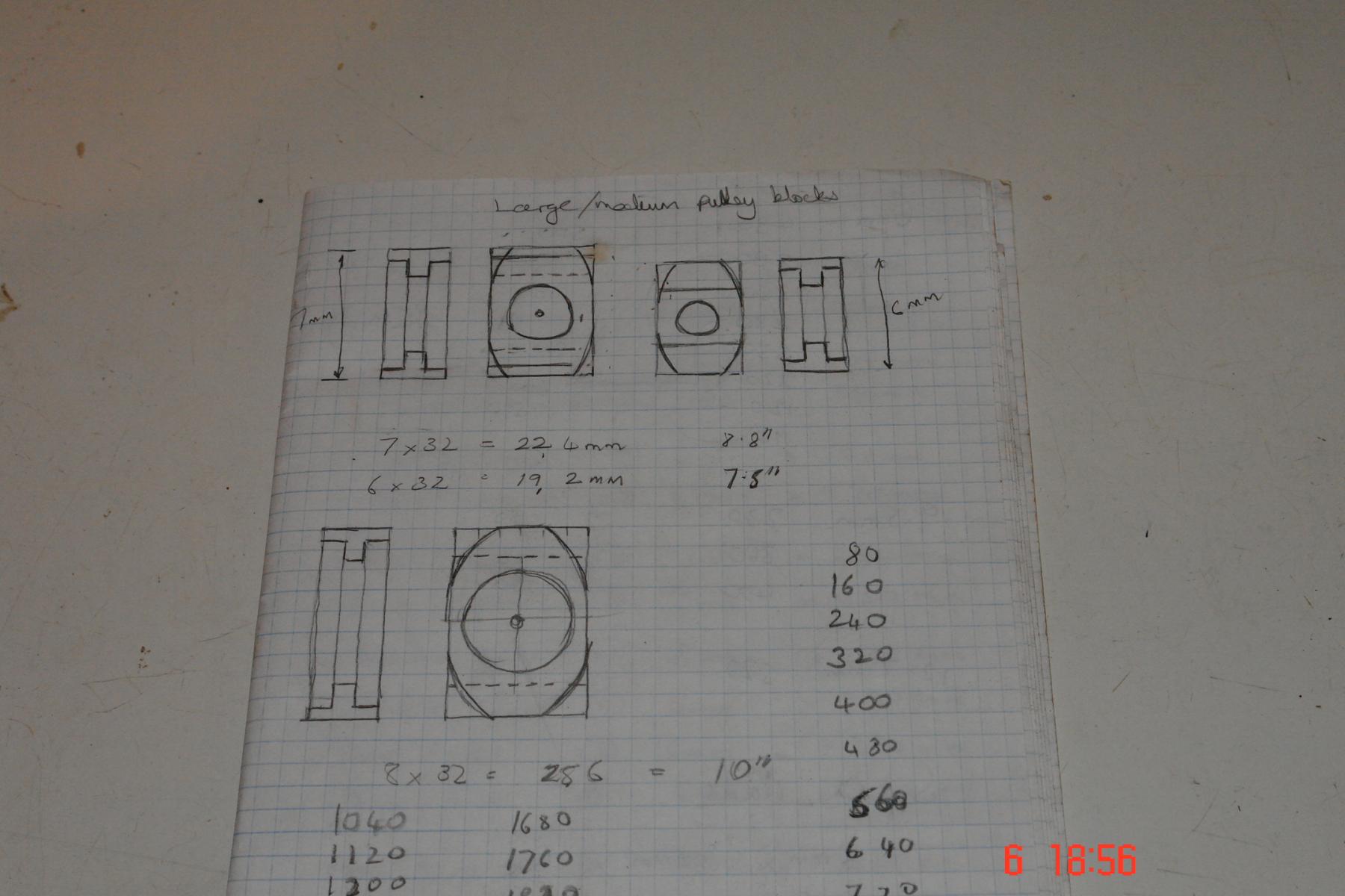
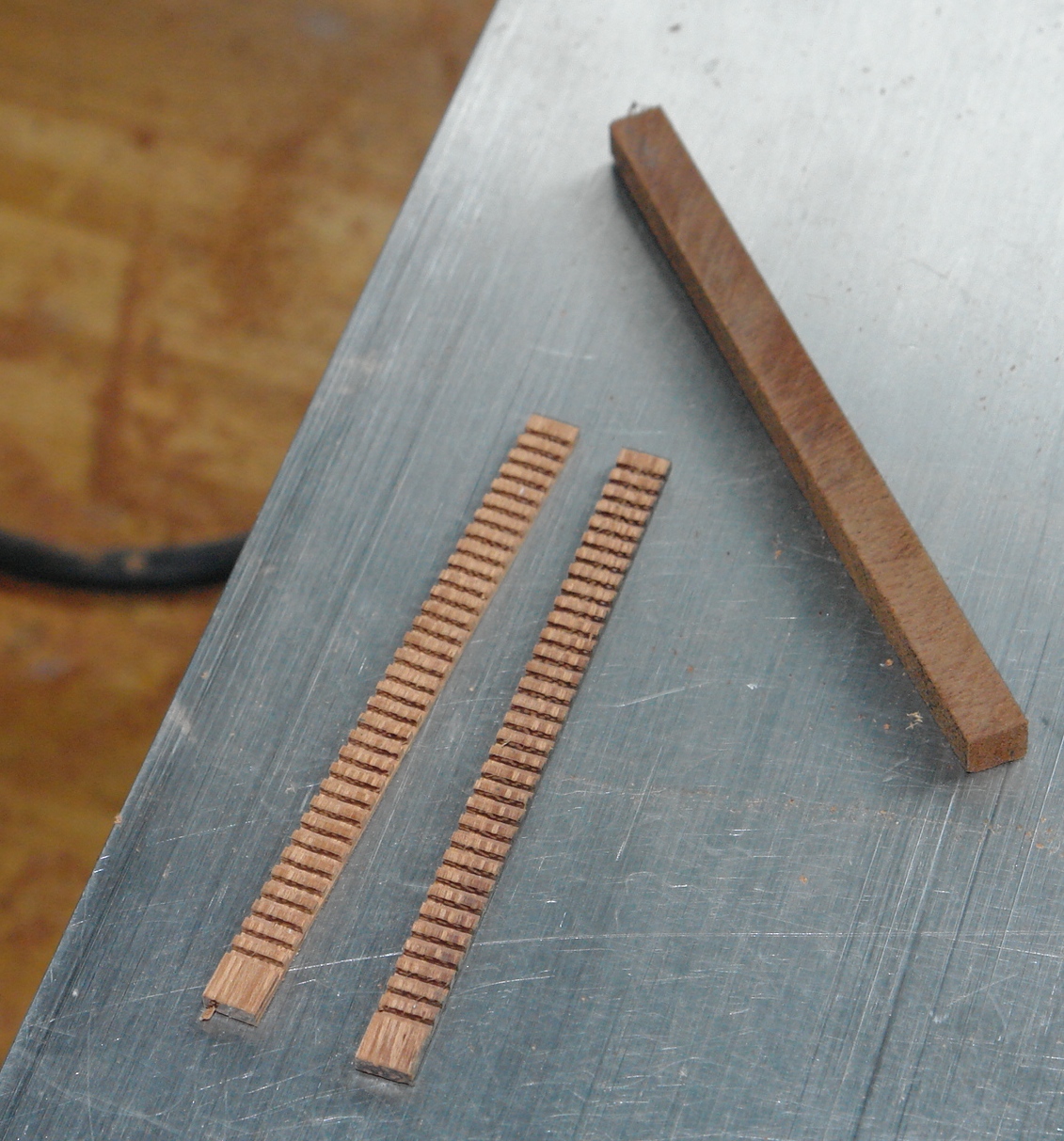
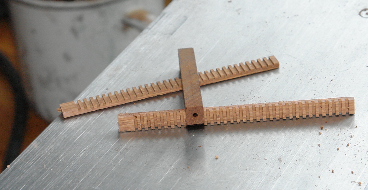
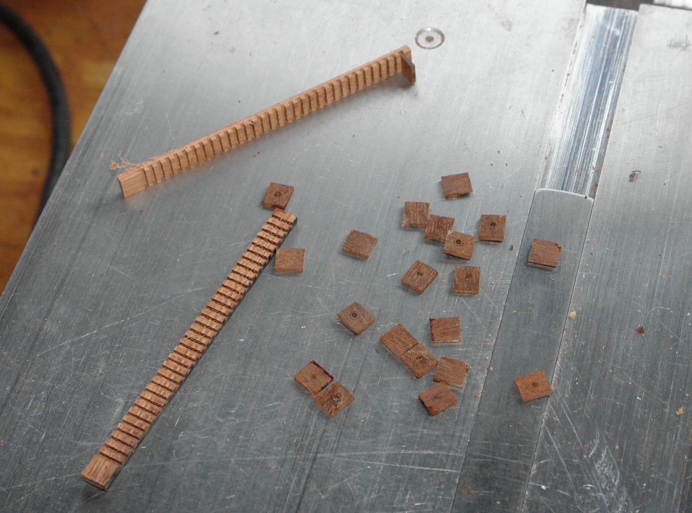
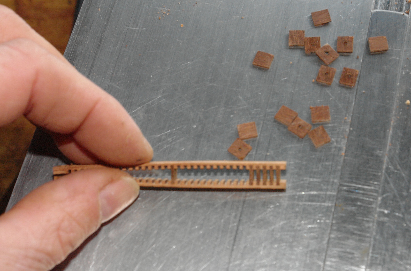
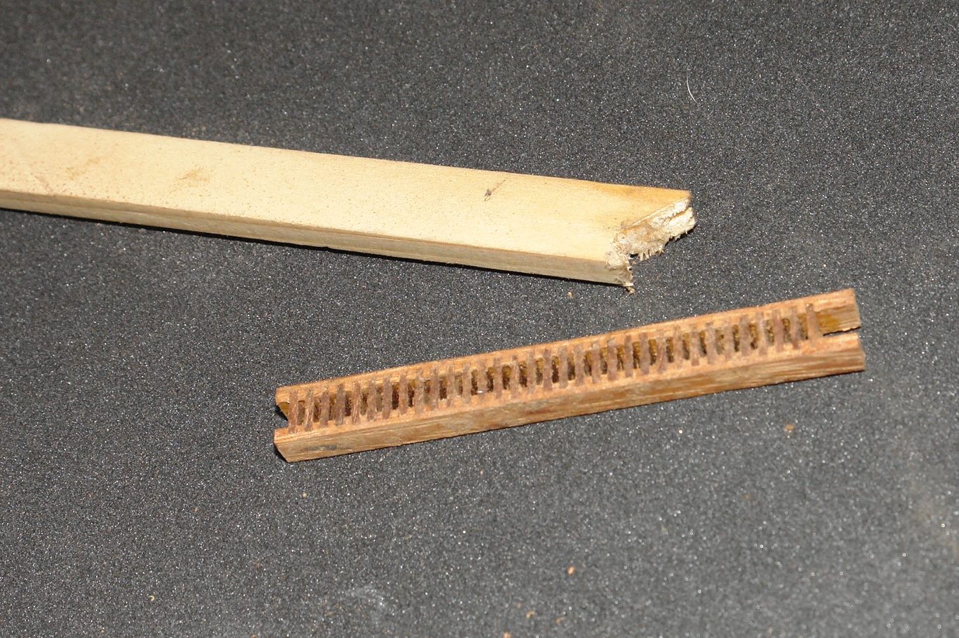
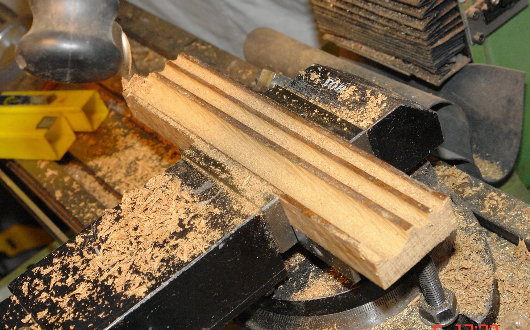
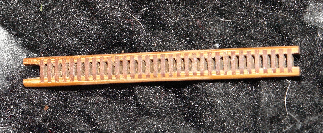
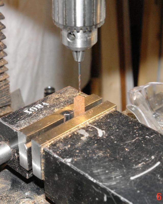
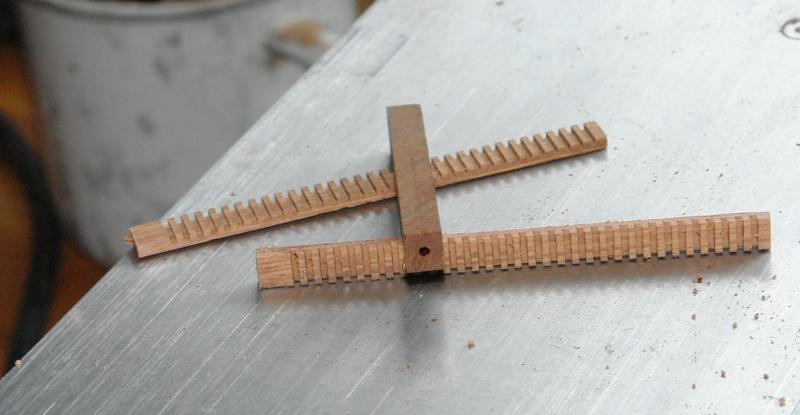
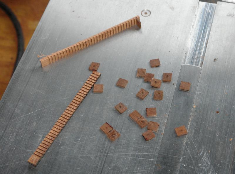
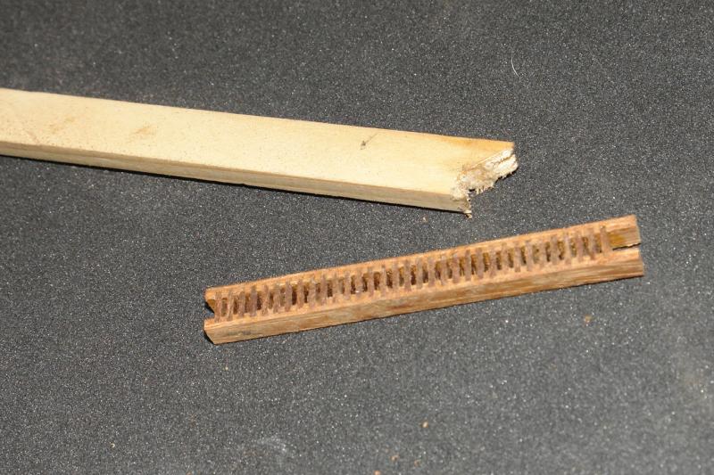
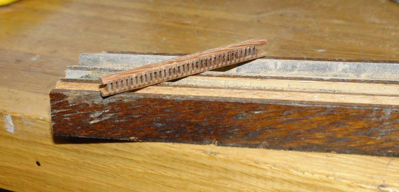
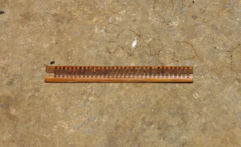
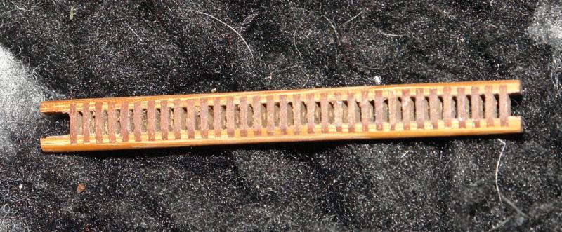
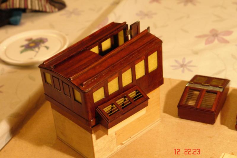
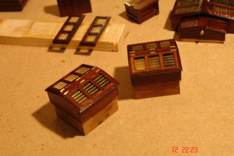
Cleats and Pulley Blocks:- On the inside of the bulwarks are cleats for attaching the fenders. 5 per side. They are fairly simple with a single central mount. I decided to have a go at making the pulley blocks. I have not made wooden pulley blocks before and decided it was worth having a try. The fall back position is buying them. Altair has single double and triple pulleys and I decided that 2 or possibly 3 sizes would cover the range needed. I started by sketching out the designs. I decided to start with the middle sized pulley block 0.2 x 0.3 inch. I need a number so decided to build them as a single unit which would allow 1,2 and 3 pulley versions to be parted off as required. I started by slotting mahogany and then cutting strips to the width of the finished pulley. I made a mistake on one of the slots - adding up becomes more difficult with age!!!!! I also cut the square block from which the walls of the pulleys would be formed. I drilled the square block to take the pulley spindle. This was a step too far as the drill was much too flexible and wandered off. Next time I will drill the spindle hole once the pulley has been formed and separated off. The wall section were slit off from the drilled block, and assembly commenced using PVA glue. Once the assembly was complete shaping commenced. I made a concave sanding block to assist control of the shaping operation. The assembly is now sanded to shape and awaiting further operations.


- 882 replies
-
- 12
-
-
Michael - re drilling the holes in the stanchions. I find that getting the drill on the centre line can be a challenge. The best way I have found to do it is to lock one axis of the mill and cut a slot in hard wood using a single pass of a cutter a coupe of thou smaller in diameter than the part to be drilled. I then press the part into the slot and drill without changing the locked setting. This works pretty well and if I want to have repeatability on the lengthways dimensions I put a nail in the slot to act as an end stop. How did you cope with centring the hole in the stanchions?
- 749 replies
-
- 5
-
-
- albertic
- ocean liner
- (and 2 more)
-
ancre La Salamandre by tadheus - 1:24
KeithAug replied to tadheus's topic in - Build logs for subjects built 1751 - 1800
Nice bricks Pawel. What are they made from? -
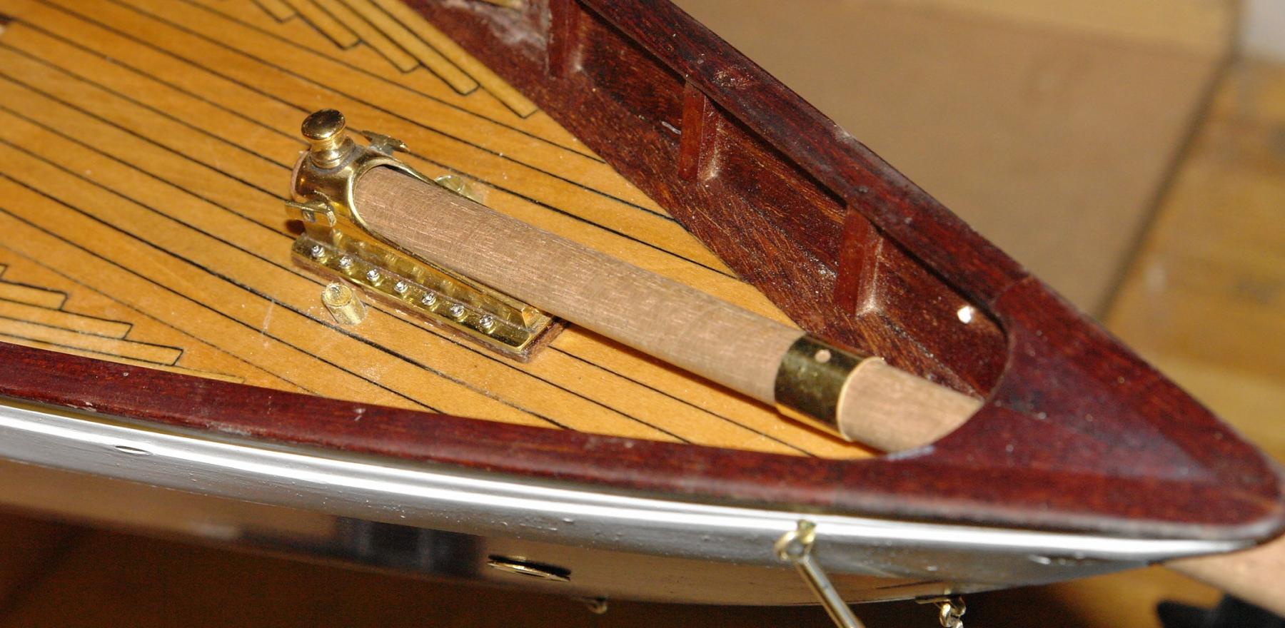
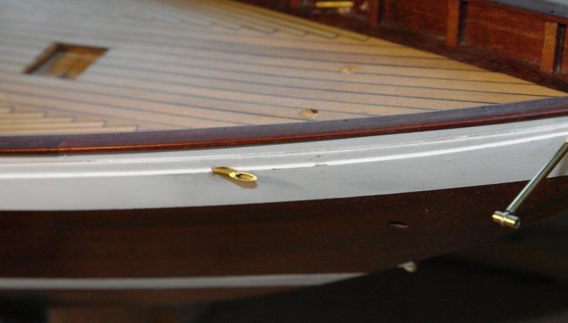
Thank you all for your kind comments and likes Following John's (Jim Lad) suggestion I mounted a sheave at the head of the bowsprit. I then finish off the other detail using bits of brass wire, tube and turned bar. I also made and fitted the reinforcing plates at the top of the hawsepipes. The mahogany for the bowsprit is light in colour and my best effort in correcting this involved 2 coats of Georgian Mahogany stain followed by 2 coats of Walnut. Not quite dark enough yet though!!!!

- 882 replies
-
- 13
-
-
ancre La Salamandre by tadheus - 1:24
KeithAug replied to tadheus's topic in - Build logs for subjects built 1751 - 1800
Pawel Thank you - Very nice - but i don't have CNC so I will have to find another way of making them. -
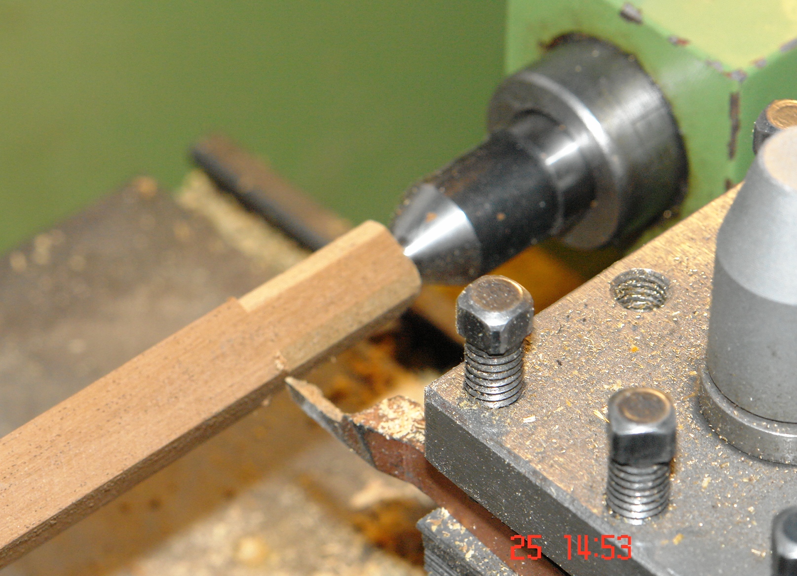
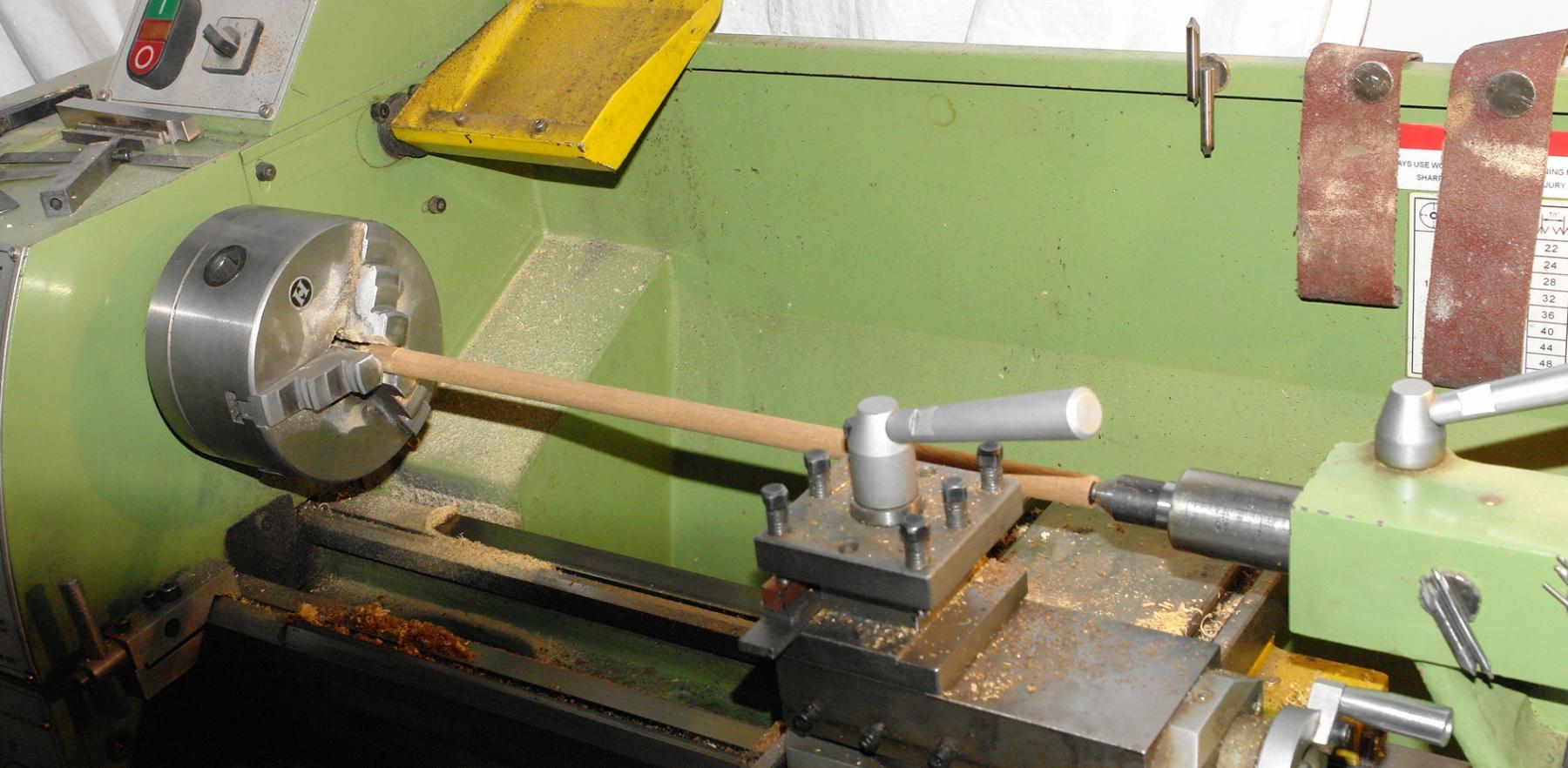
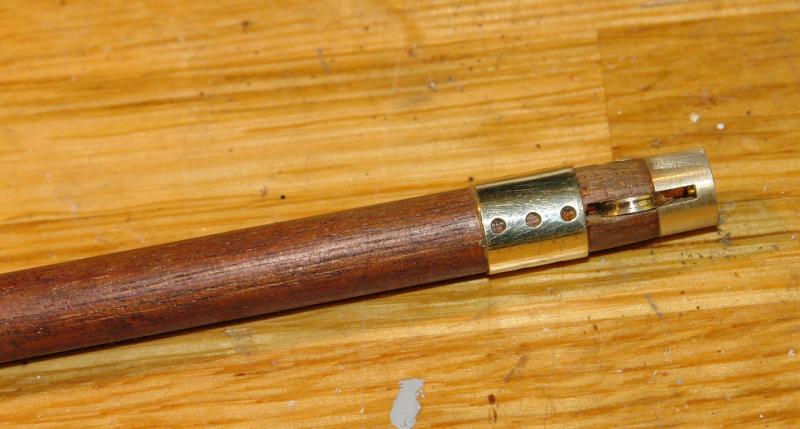
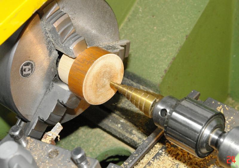
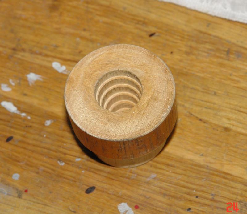
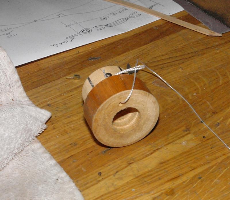
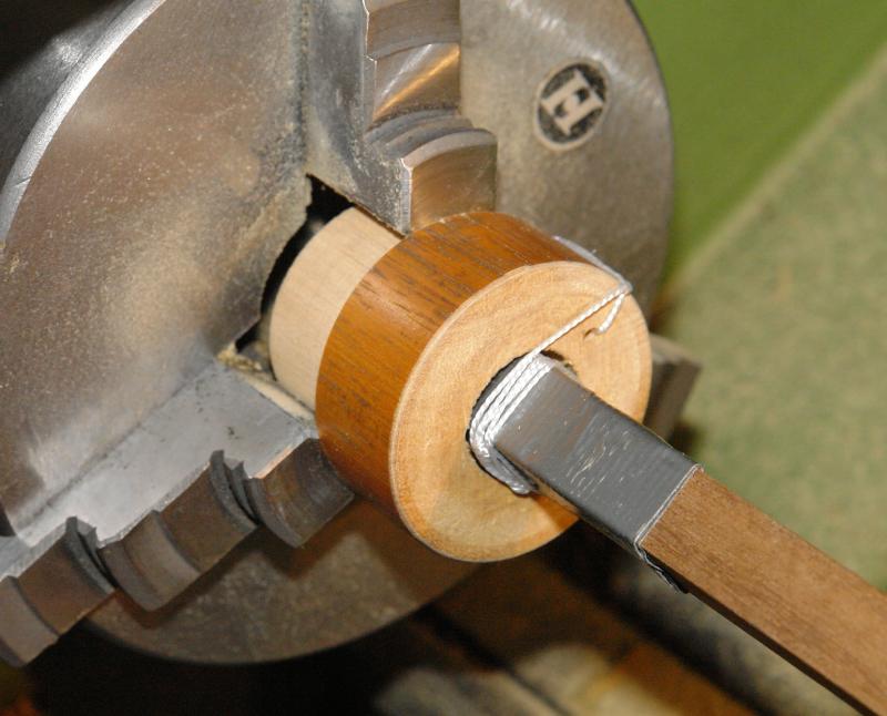
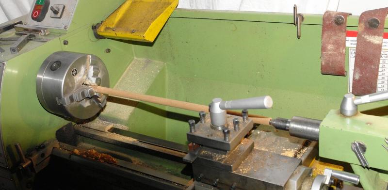
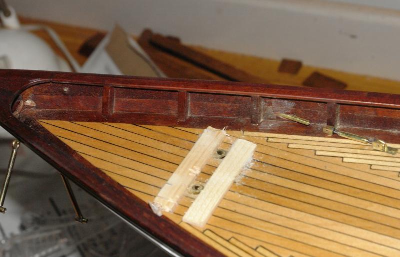
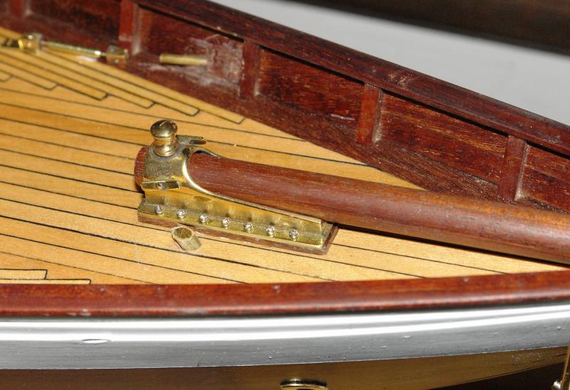
My time has been much diverted so progress has been slow. I decided to make the bowsprit but only had square section timber available. I have a 4 jaw independent chuck but changing over from the 3 jaw chuck is very tedious and I wanted to find a quick solution to holding square section stock for masts and spars. The primary requirement was to hold and drive the square section stock while turning the diameter at the opposite end. I made a wooden hub with concentric bore diameters. The concentric diameters being made in a single operation using a step drill. The square section of the timber goes into the nearest across corners diameter hole. A piece of sting provides the drive and the tape takes up any slack in the fit. I installed the hawsepipes. The upper ends were filed to the correct length and angle using wooden guides temporally held in place by double sided tape. I mounted the bowsprit foot on the deck. The bolts holding the foot down are reading glasses repair screws - from ebay.


- 882 replies
-
- 13
-
-
ancre La Salamandre by tadheus - 1:24
KeithAug replied to tadheus's topic in - Build logs for subjects built 1751 - 1800
Pawel A bit of information on how you made the blocks would be quite helpful. I have a number to make. Thank you. -
Thanks John. That seems to be the most sensible solution and has the benefit that it will look right. I'll go with it.
-
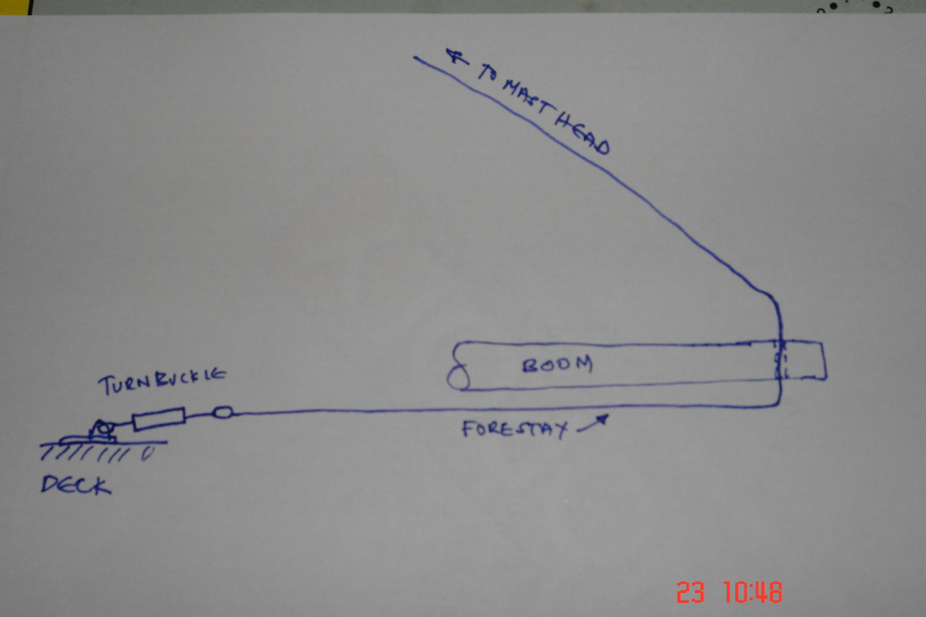
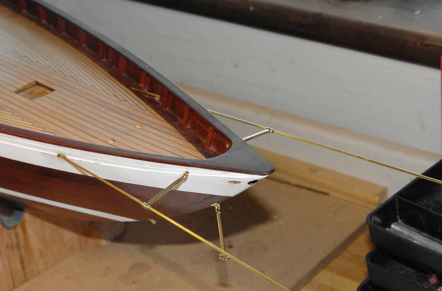
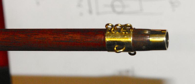
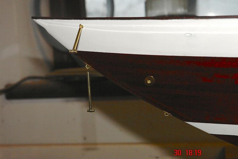
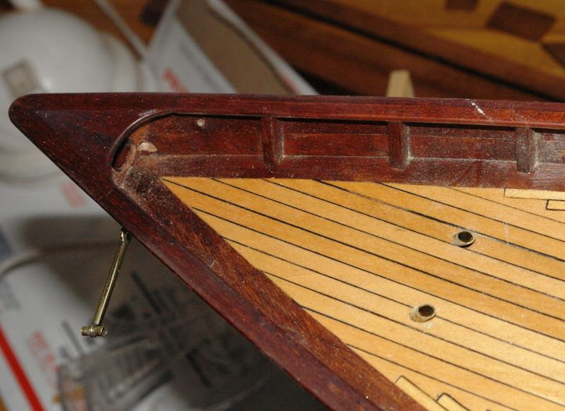
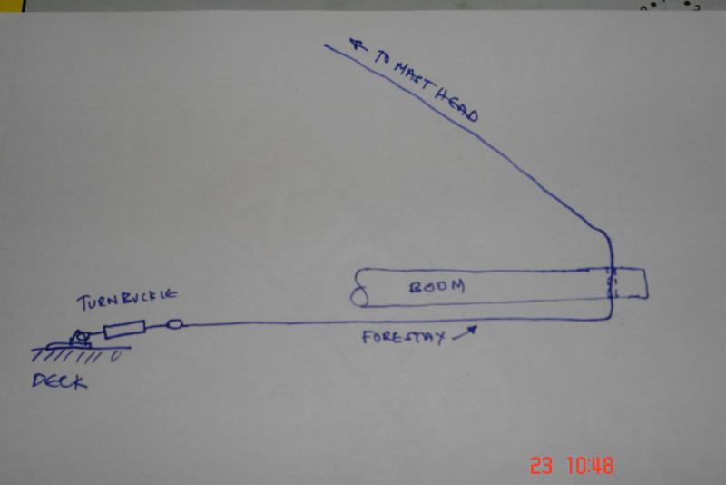
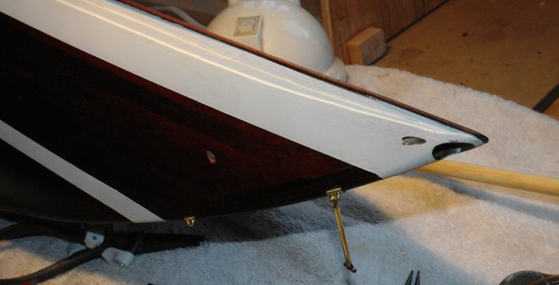
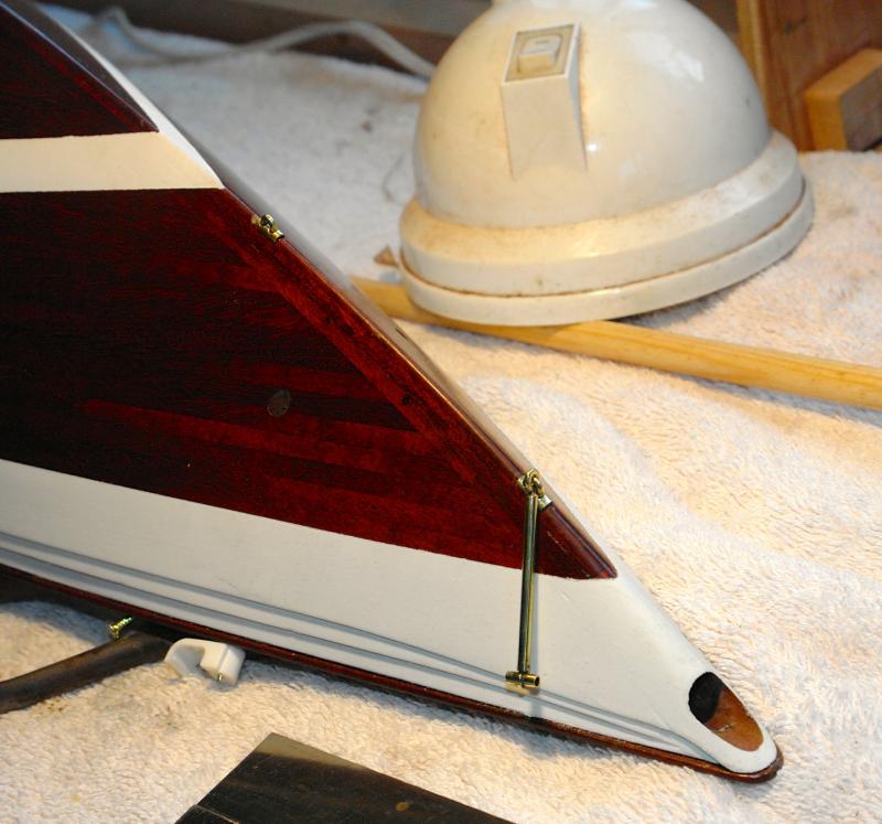
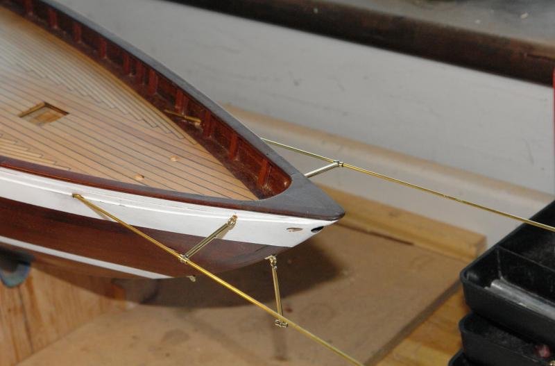
Hello Members I am seeking some advice from those of you familiar with classic yacht or similar rigging. The plans for Altair show the forestay shroud starting at a turnbuckle that lies alongside the foot of the jib boom. From here the stay passes through the bulwark at the bow and on to the forward end of the jib boom. It then continues upwards to the head of the foremast. The issue I have is with the plan detail at the forward end of the jib boom. The plan shows the stay entering the bottom of vertical hole at the end of the boom, then passing through the boom before heading back at an angle of 60 deg to the mast head (see diagram). Clearly this is impractical as the forces imparted by tightening the turnbuckle would be all but completely dissipated by the geometry of the cable / hole. My guess is that some form of pulley is mounted at the front of the jib boom to maximise the transmission of tensile force to the forestay. However I am guessing. Do any of you know the usual or correct arrangement?
-
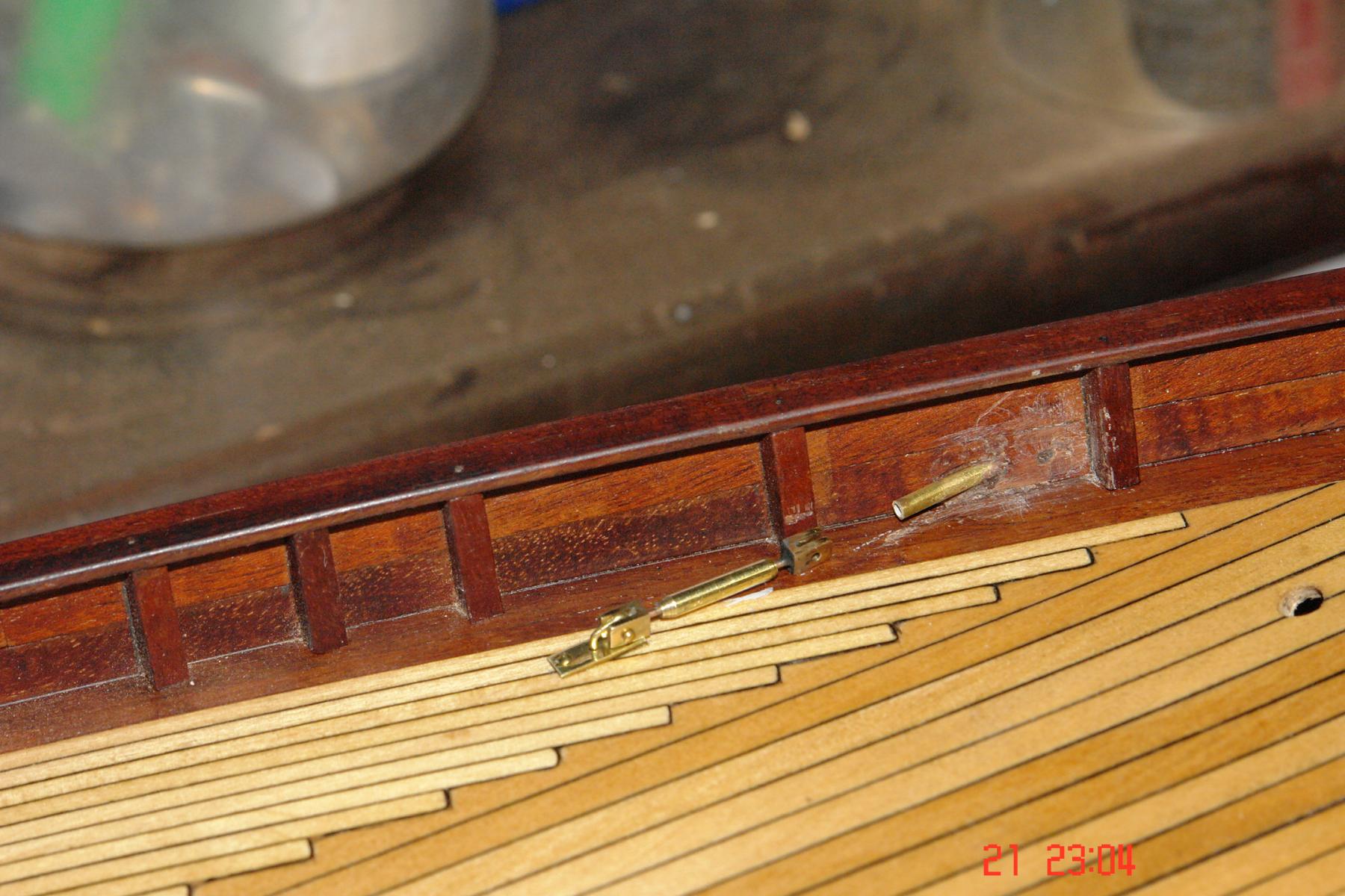
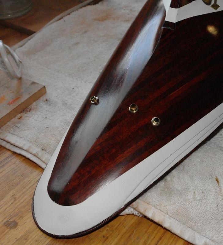
The holes in the bulwark through which the martingales pass turned out quite neatly, so I was pleased that i went to the trouble of using a brass sleeve. I spent most of the day making the turnbuckles for the martingales.
- 882 replies
-
- 16
-
-
ancre La Salamandre by tadheus - 1:24
KeithAug replied to tadheus's topic in - Build logs for subjects built 1751 - 1800
Excellent as usual Pawel. -
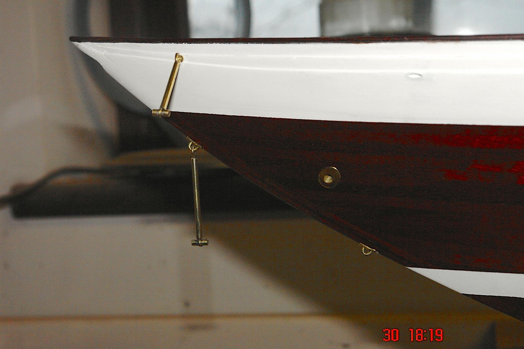
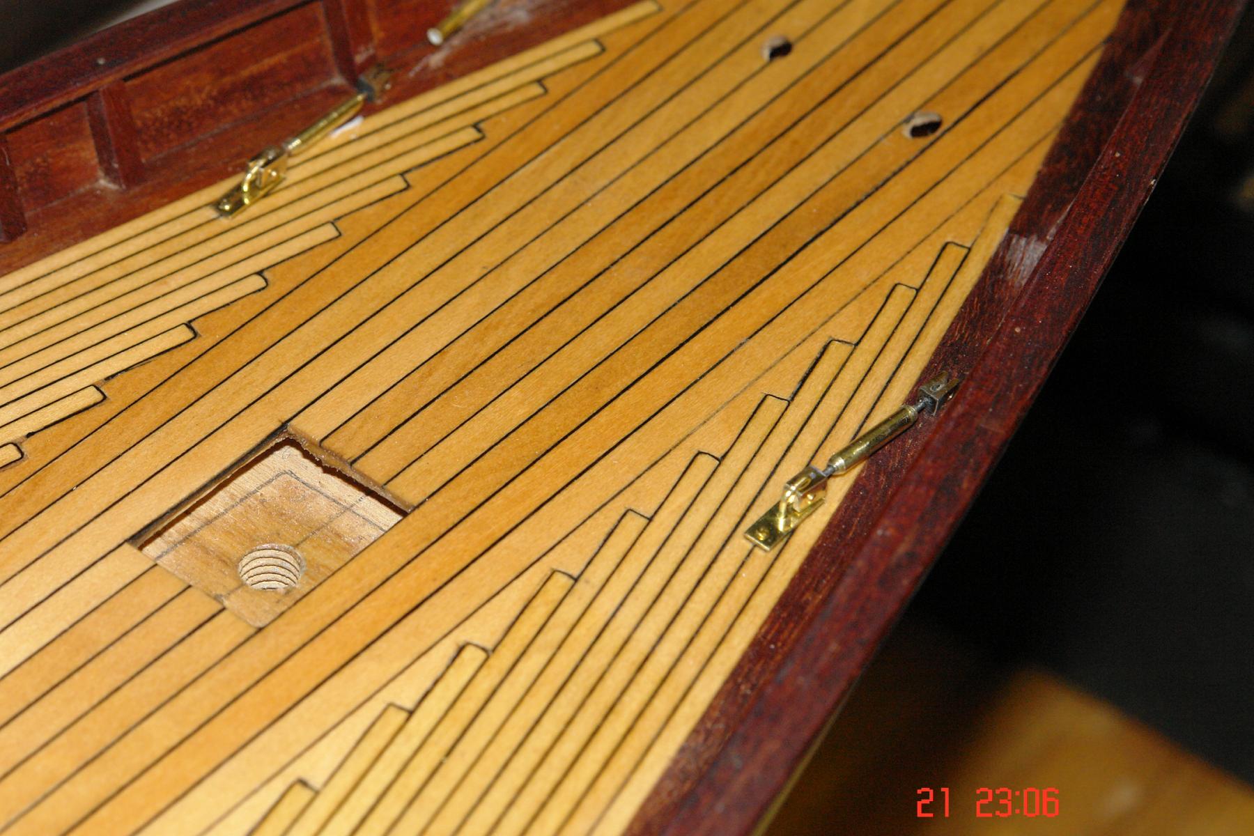
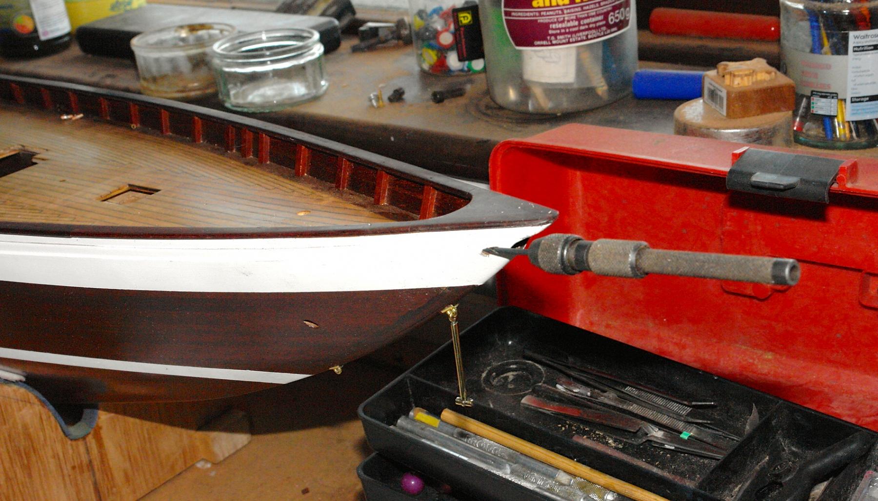
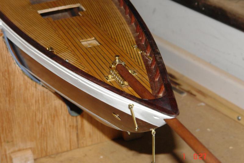
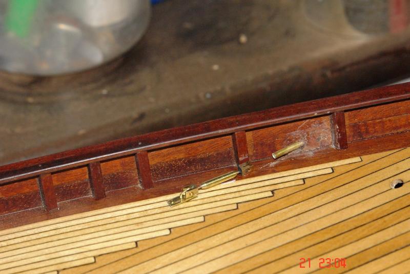
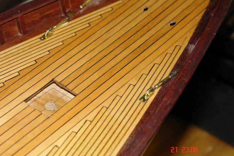
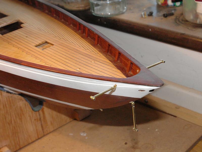
Today I got on with a bit of brass work. Under the stern are 3 discharge pipes. I made a start on a bit of detail at the bow. A small hole had to be drilled parallel to the hole in the bulwark for the jib boom. The fore topmast stay passes through this hole. The angles are a bit complex so I decided to take drilling easy using a pin vice. I also made and attached the dolphin striker and the 2 outriggers for the martingales. Obliquely angled holes pass through the bulwark to take the martingales. I decided to line these with brass tubes to give a crisp edge. Again I drilled using the pin vice and corrected the angle using a round needle file. It took an age to get the angles correct. I should have done this before painting as now touching up will be necessary. You live and learn! I used brass rod to make sure the tubes were correctly aligned while glueing.

- 882 replies
-
- 15
-
-
Hello Julie Thank you for the comments. Maybe you need to plan shipbuilding for the summer months.
-
ancre La Salamandre by tadheus - 1:24
KeithAug replied to tadheus's topic in - Build logs for subjects built 1751 - 1800
Pawel The view along the deck is just like standing on a real ship. Lovely work. -
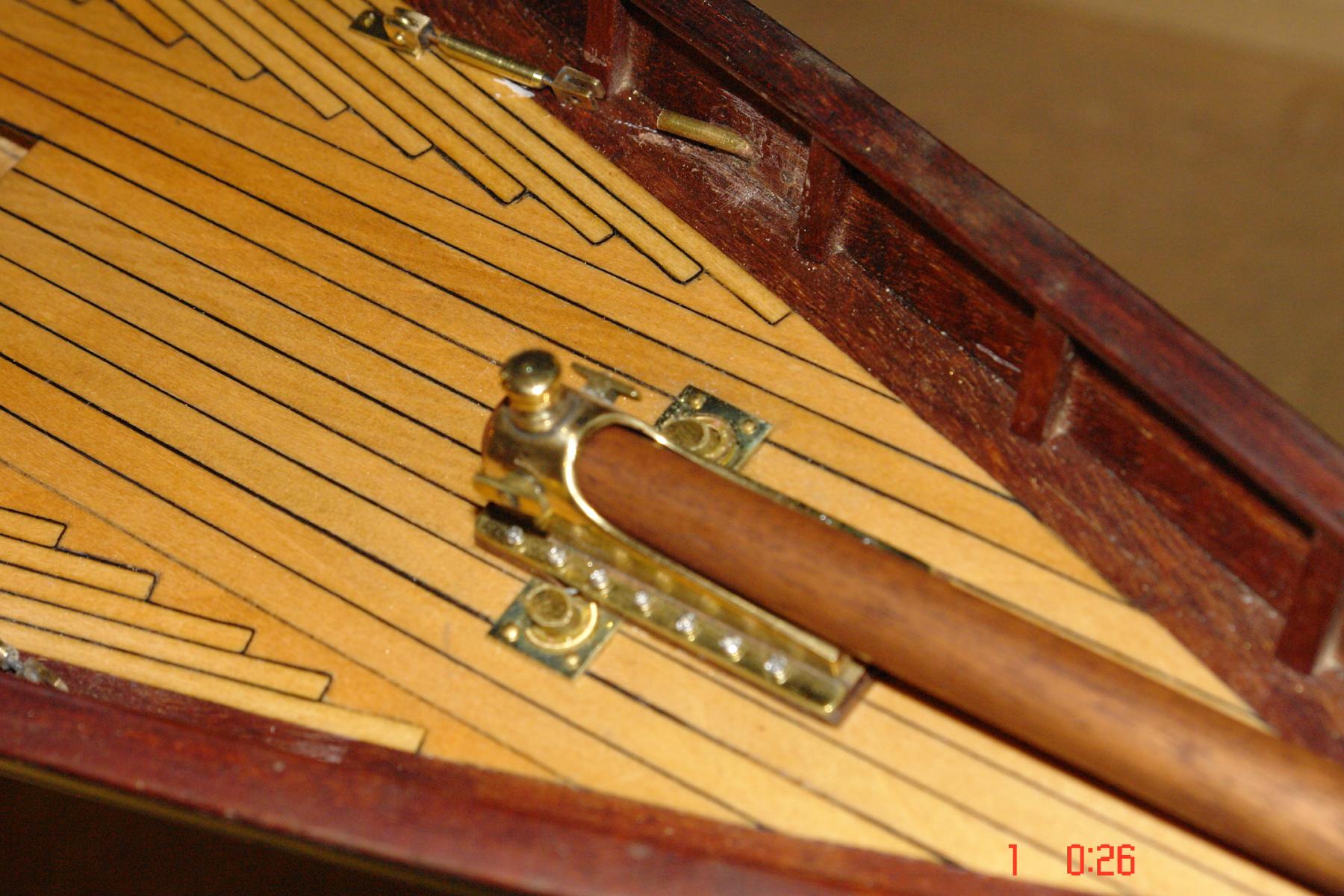
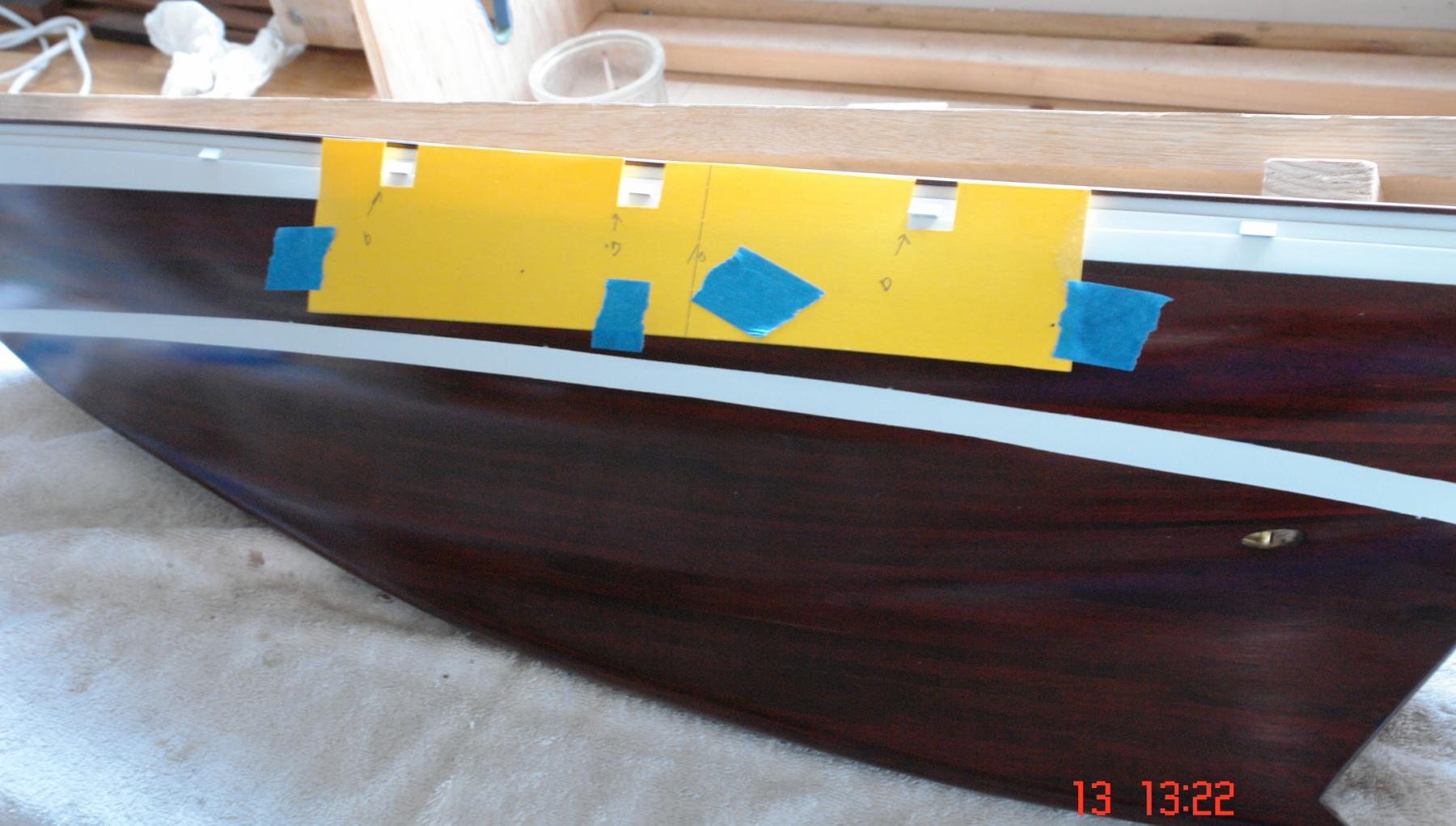
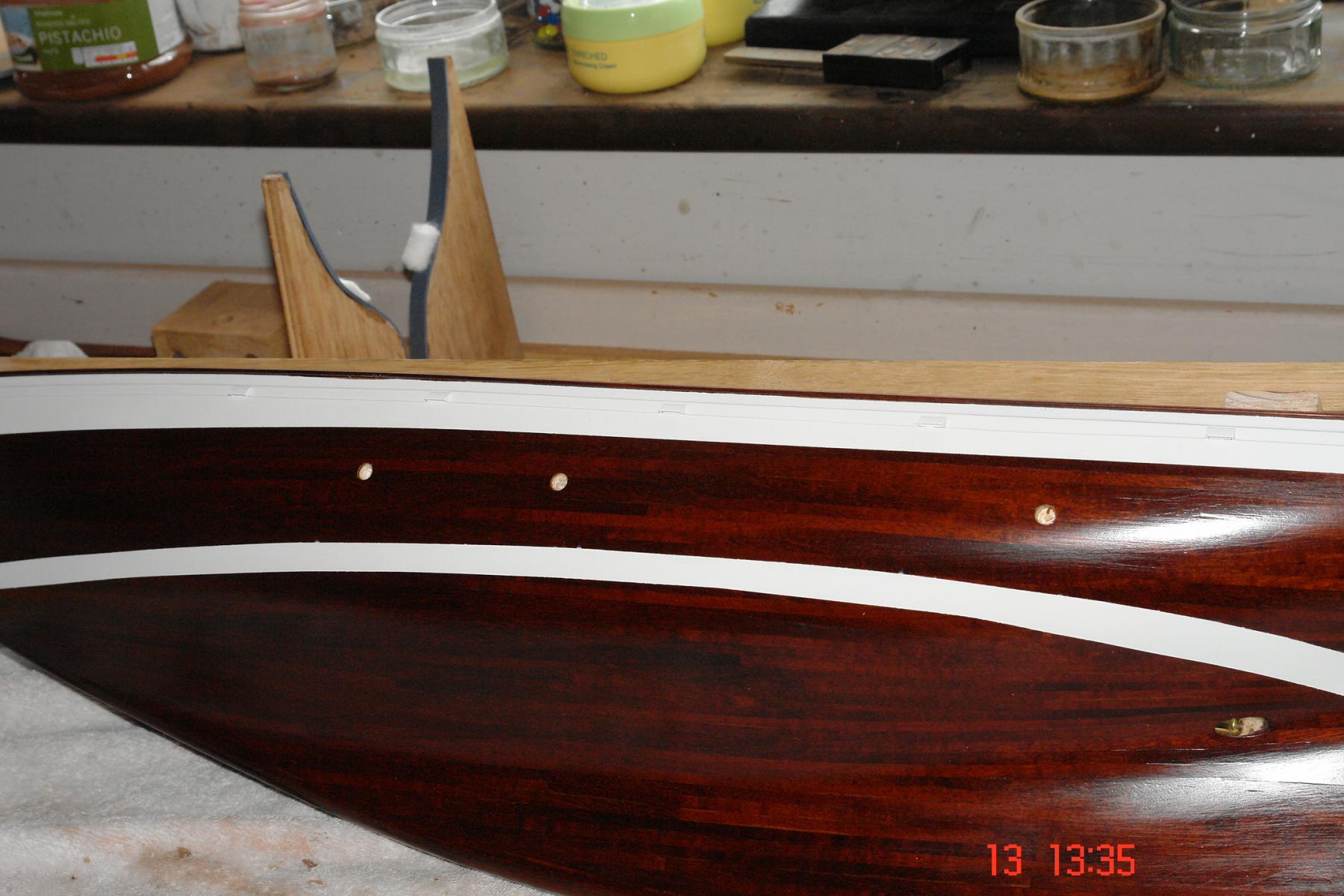
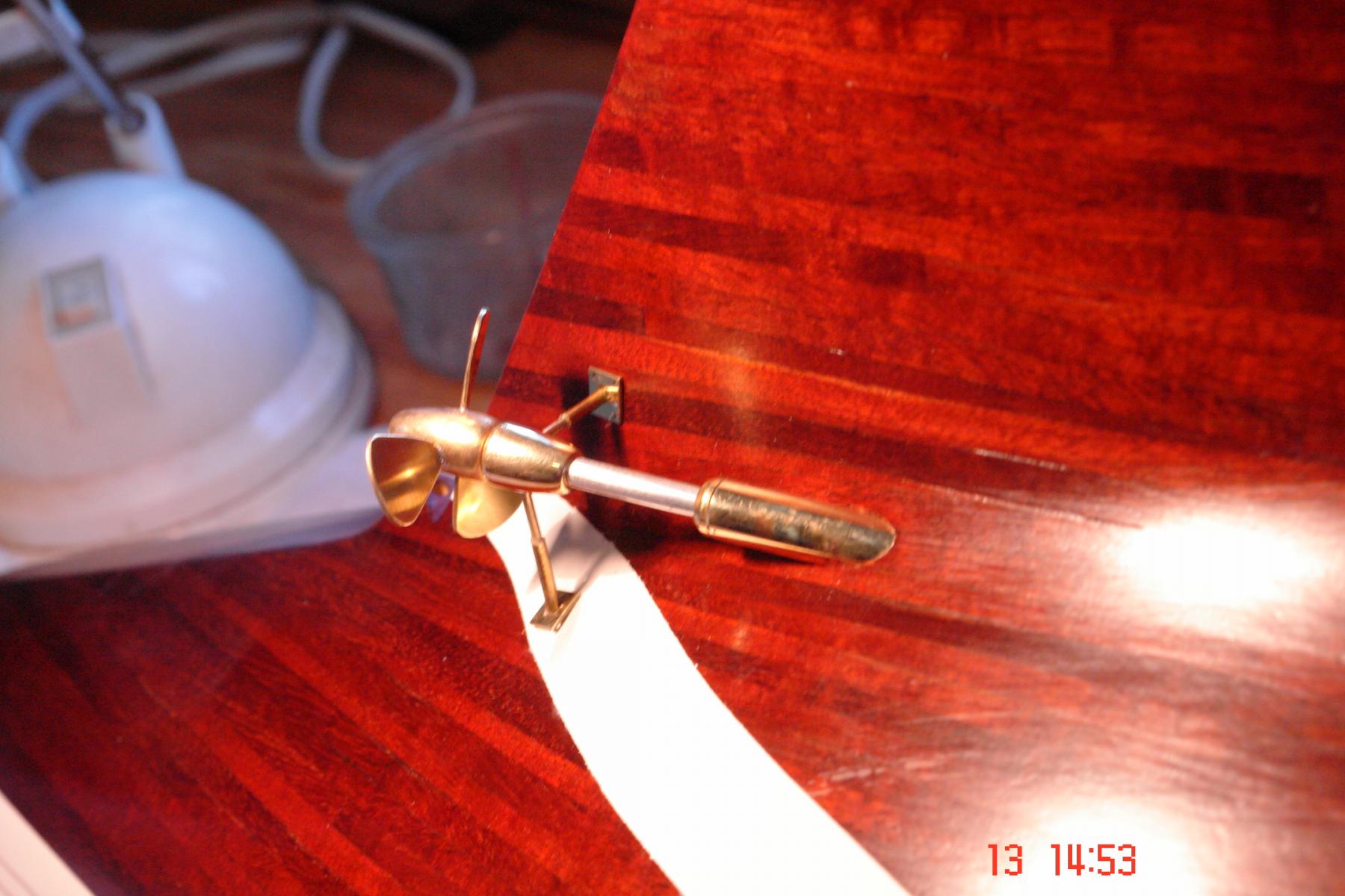
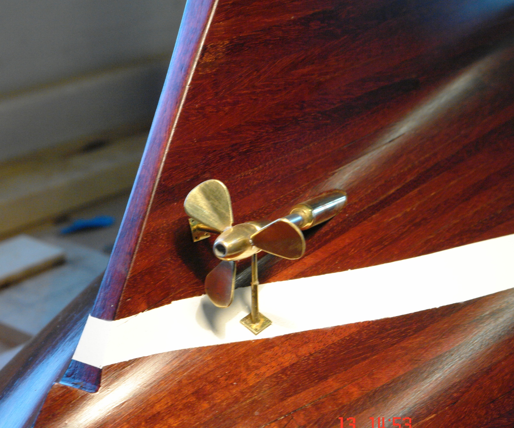
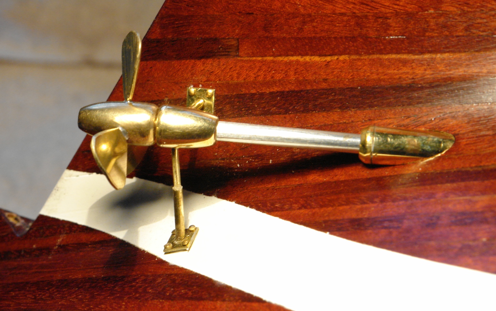
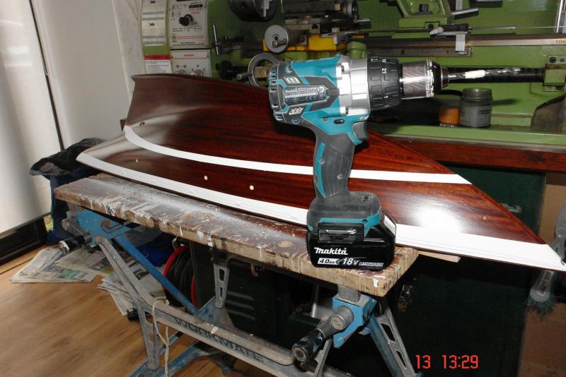
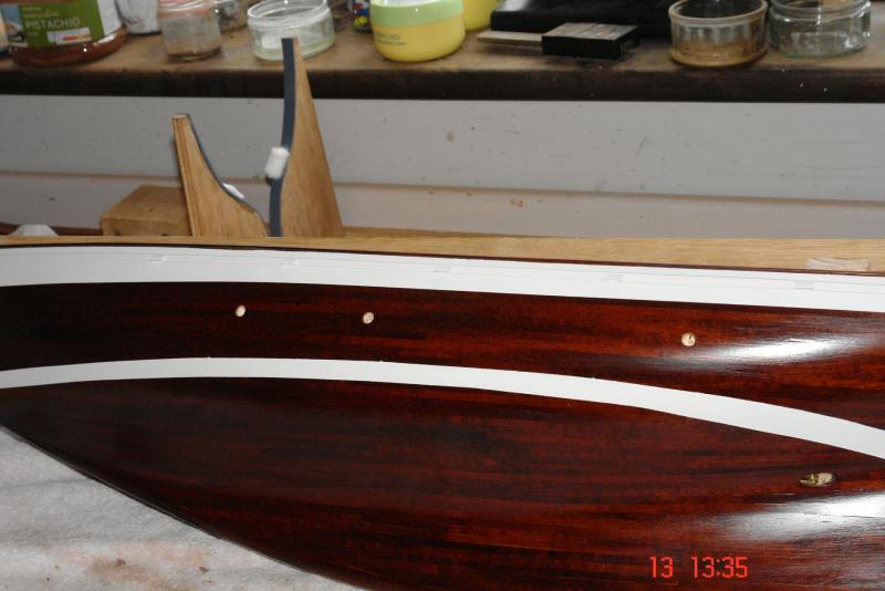
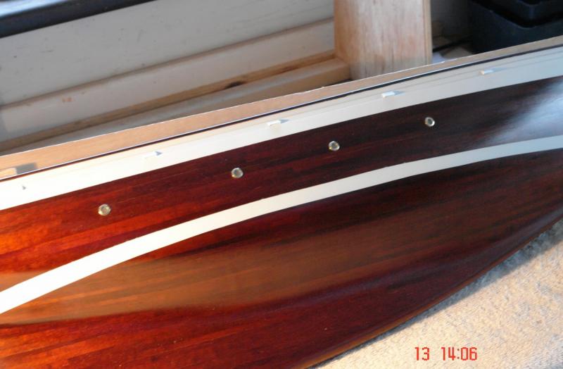
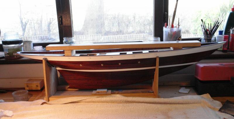
Thank you Bedford. Hello Wintergreen, thanks for visiting my build. Its good to get feedback from a fellow yachtsman. Today was the last day of building for a few days. A 50th wedding anaversary to go to and the brother in law and wife then arriving from Arizona. I think they will find the temperature difference a bit extreme. Returning to the build. In trepidation I decided to take my rather powerful DIY drill to the hull. I needed to mount the portholes - 7 in total - 4 starboard and 3 port, this required the boring of .250 inch dia holes by .250 inch deep. I wanted to get the positioning spot on so I used a card template which I transferred from side to side. The holes were drilled slightly undersize and finished off with emery cloth glued to a piece of dowel. The previously made portholes (covered earlier) were glued in place with ca. I also finished off mounting the screw. The "A" frame was glued into the hull and the mounting plates pinned in place.


- 882 replies
-
- 17
-
-
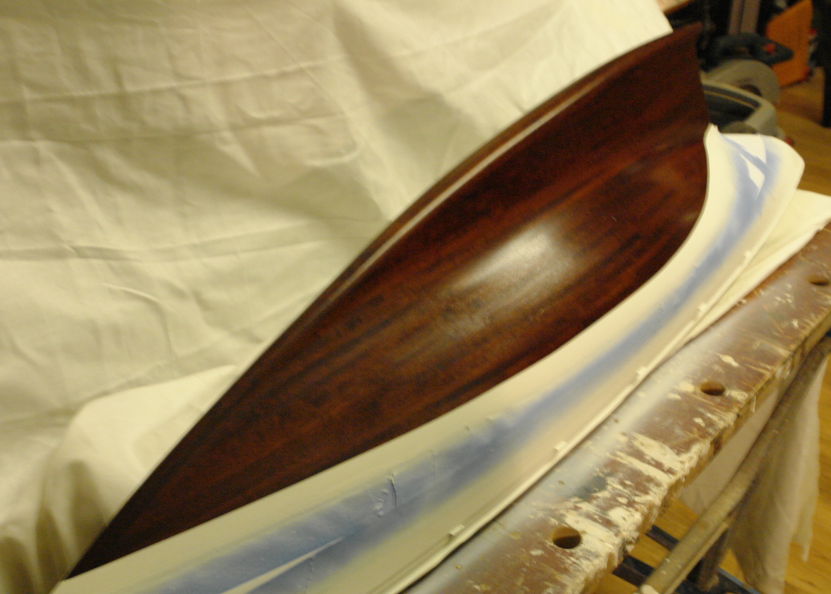
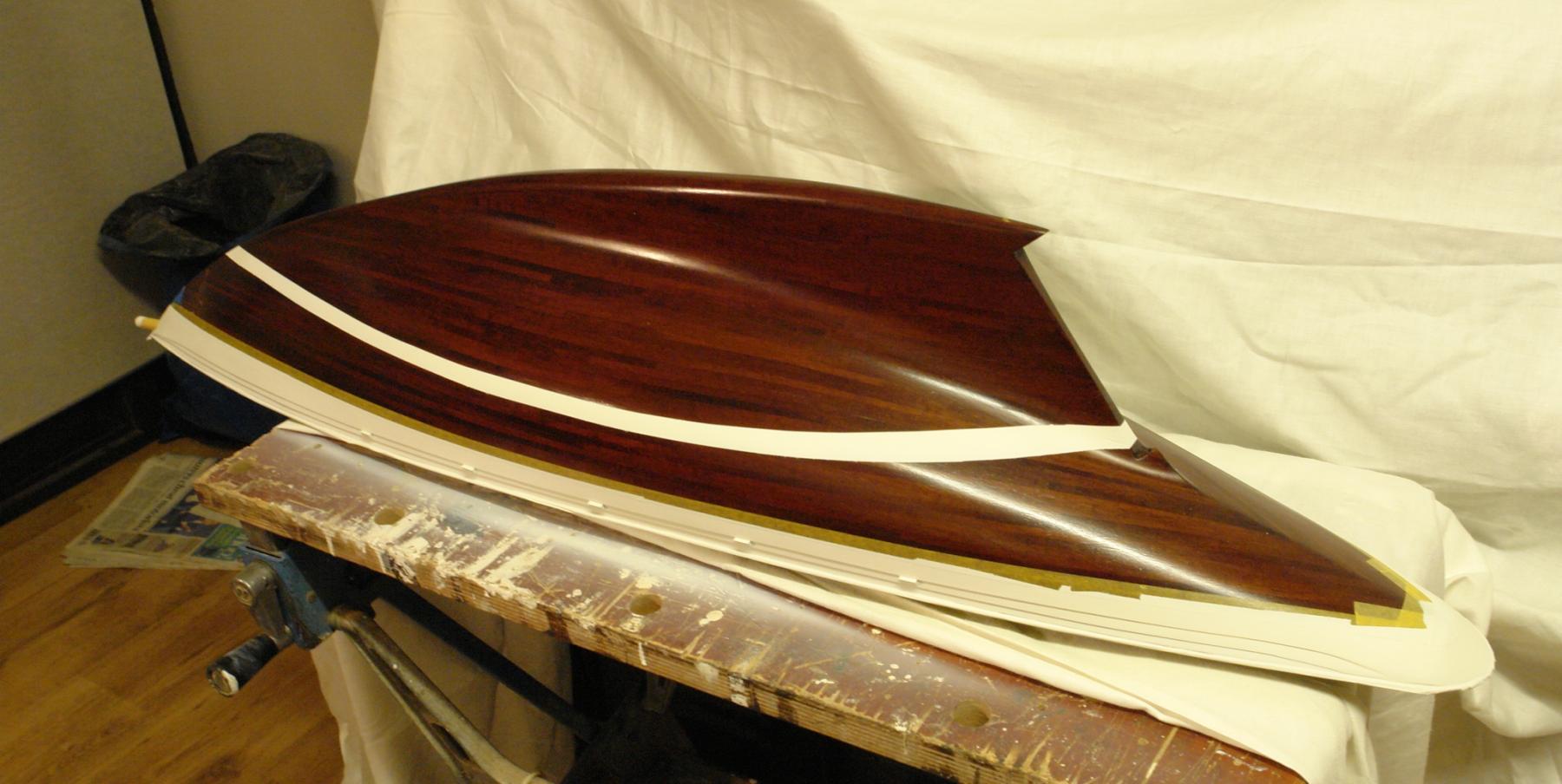
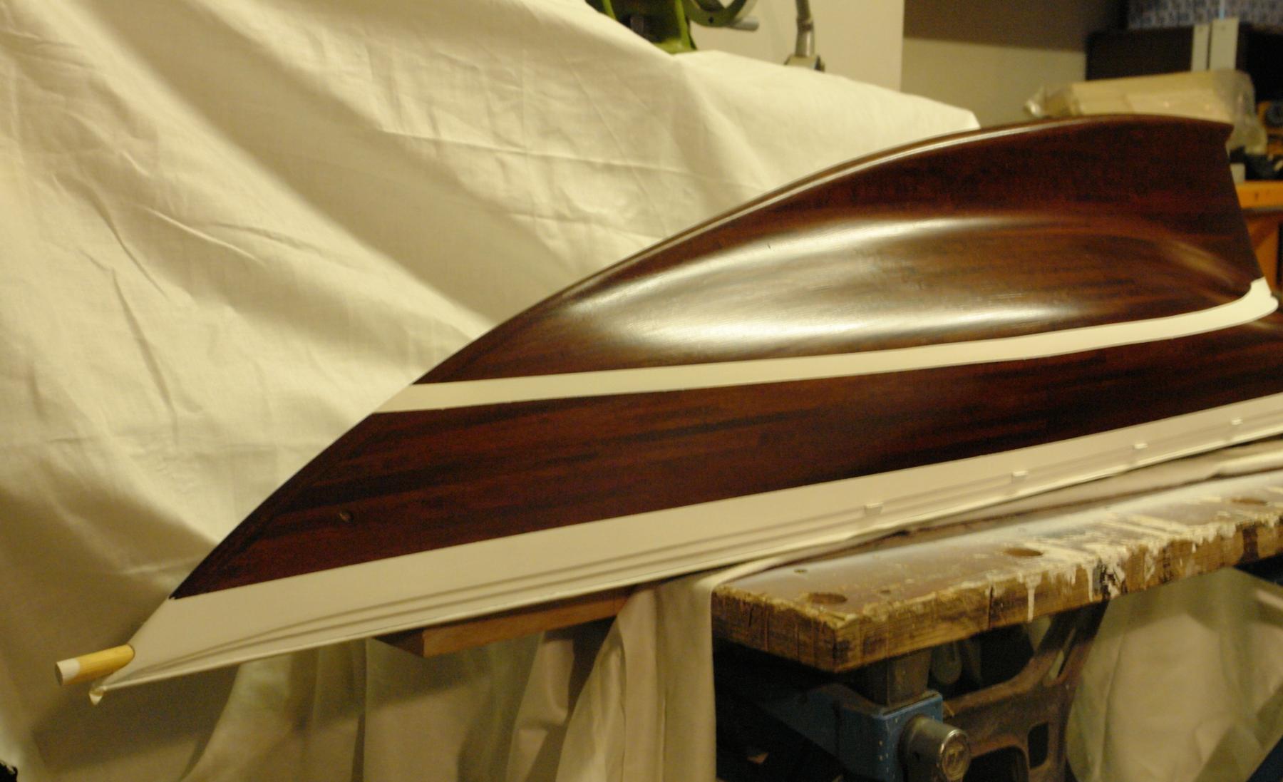
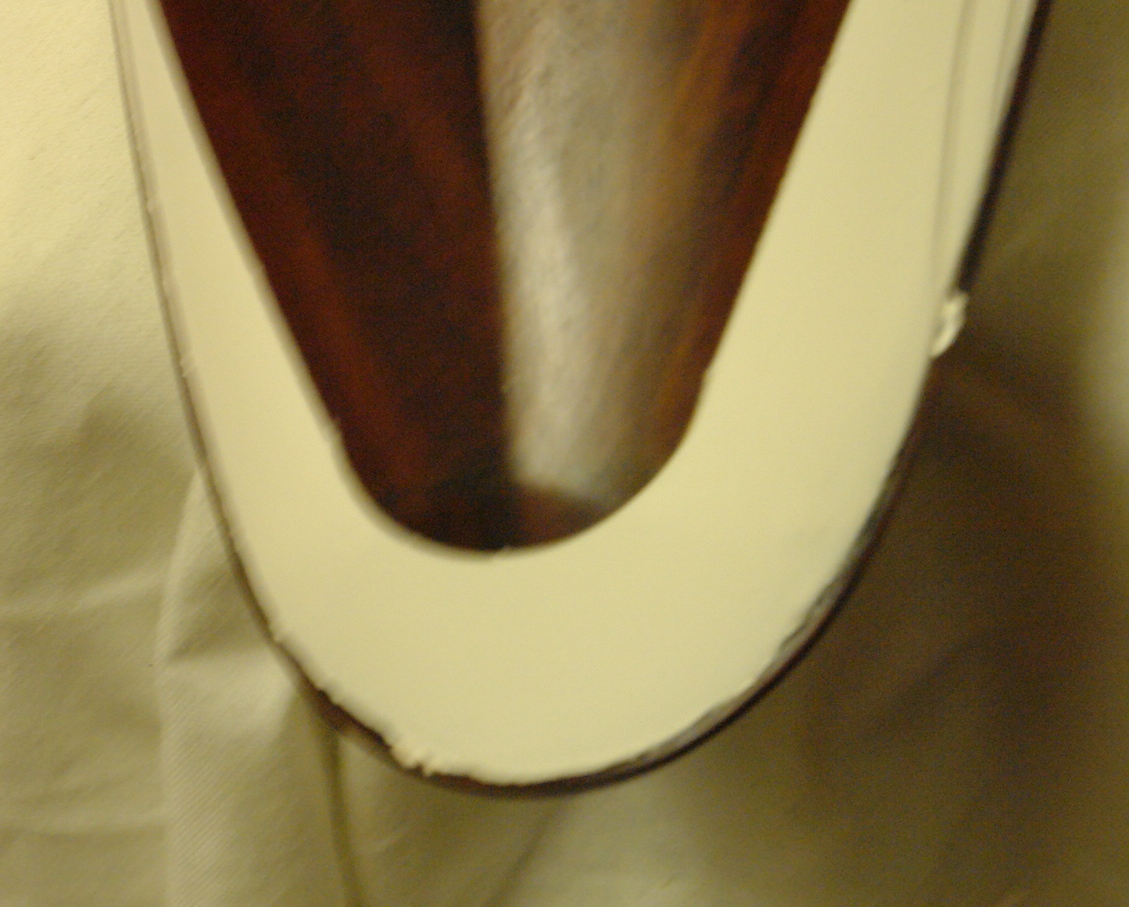
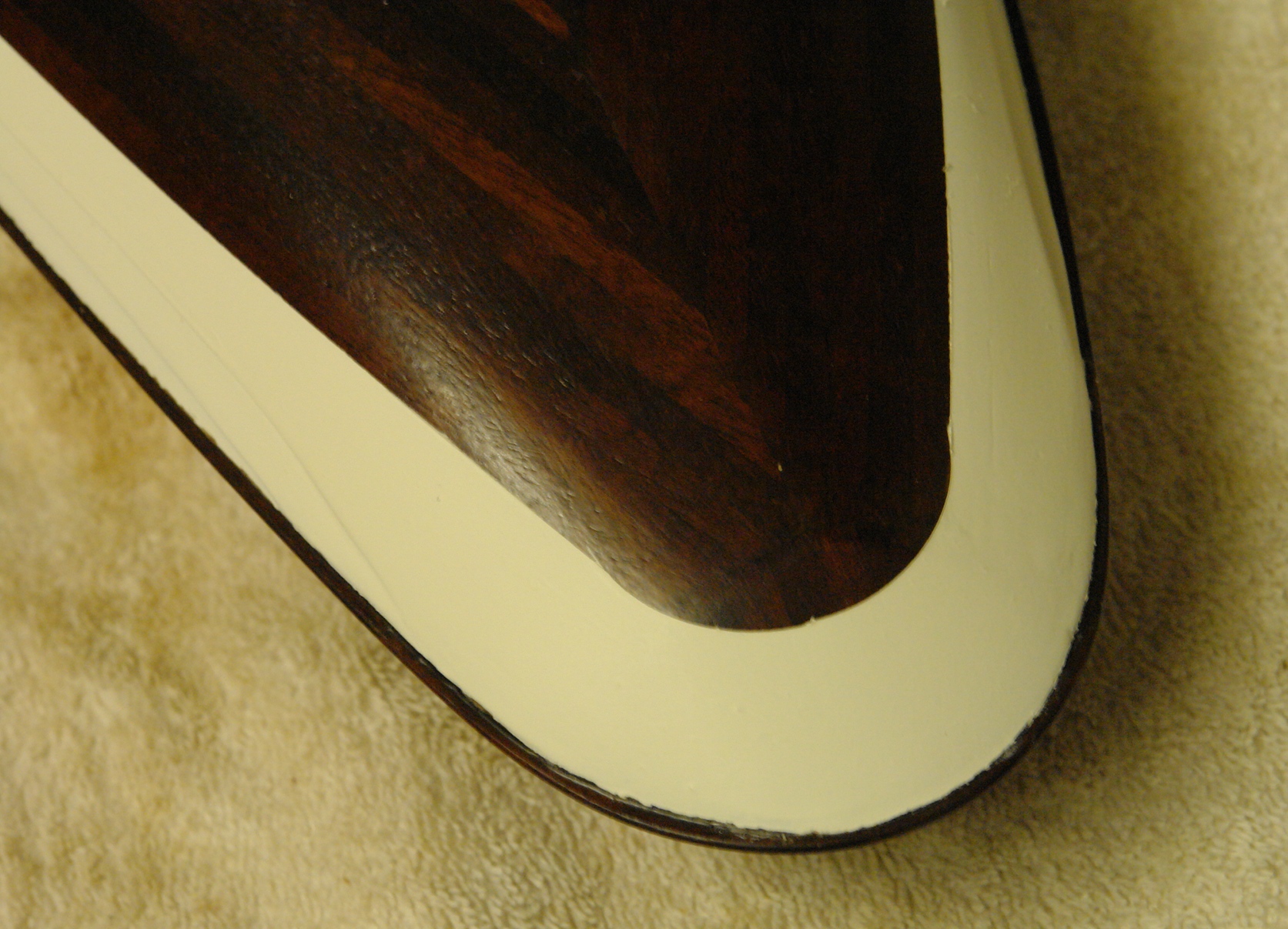
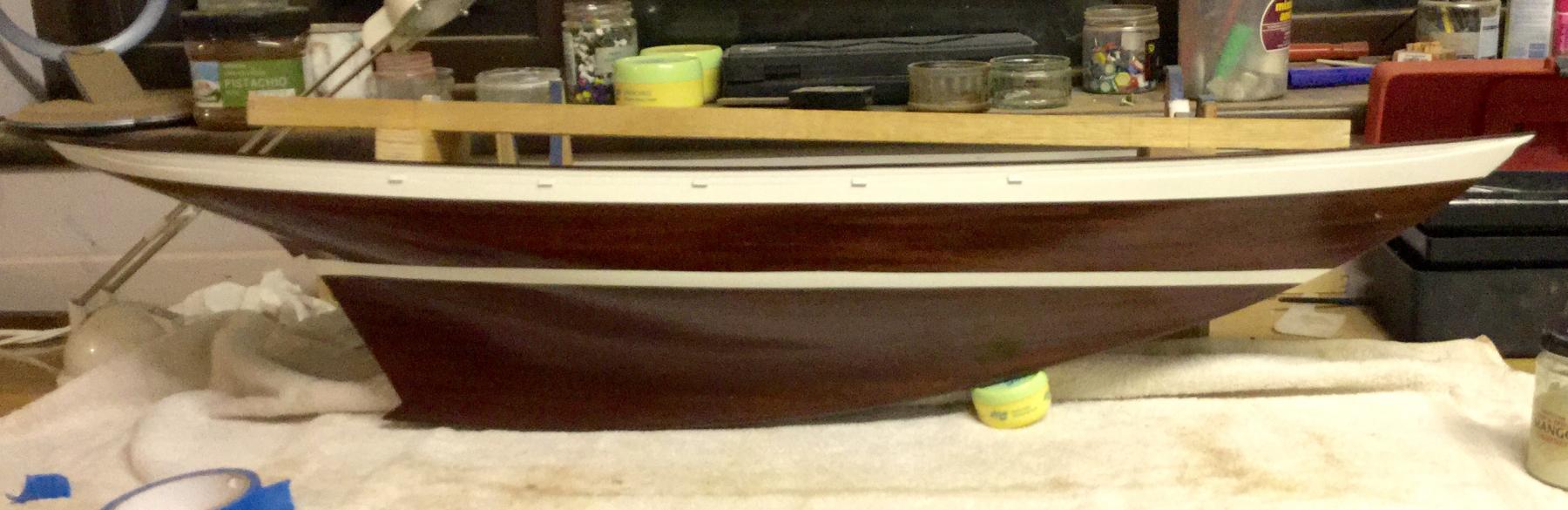
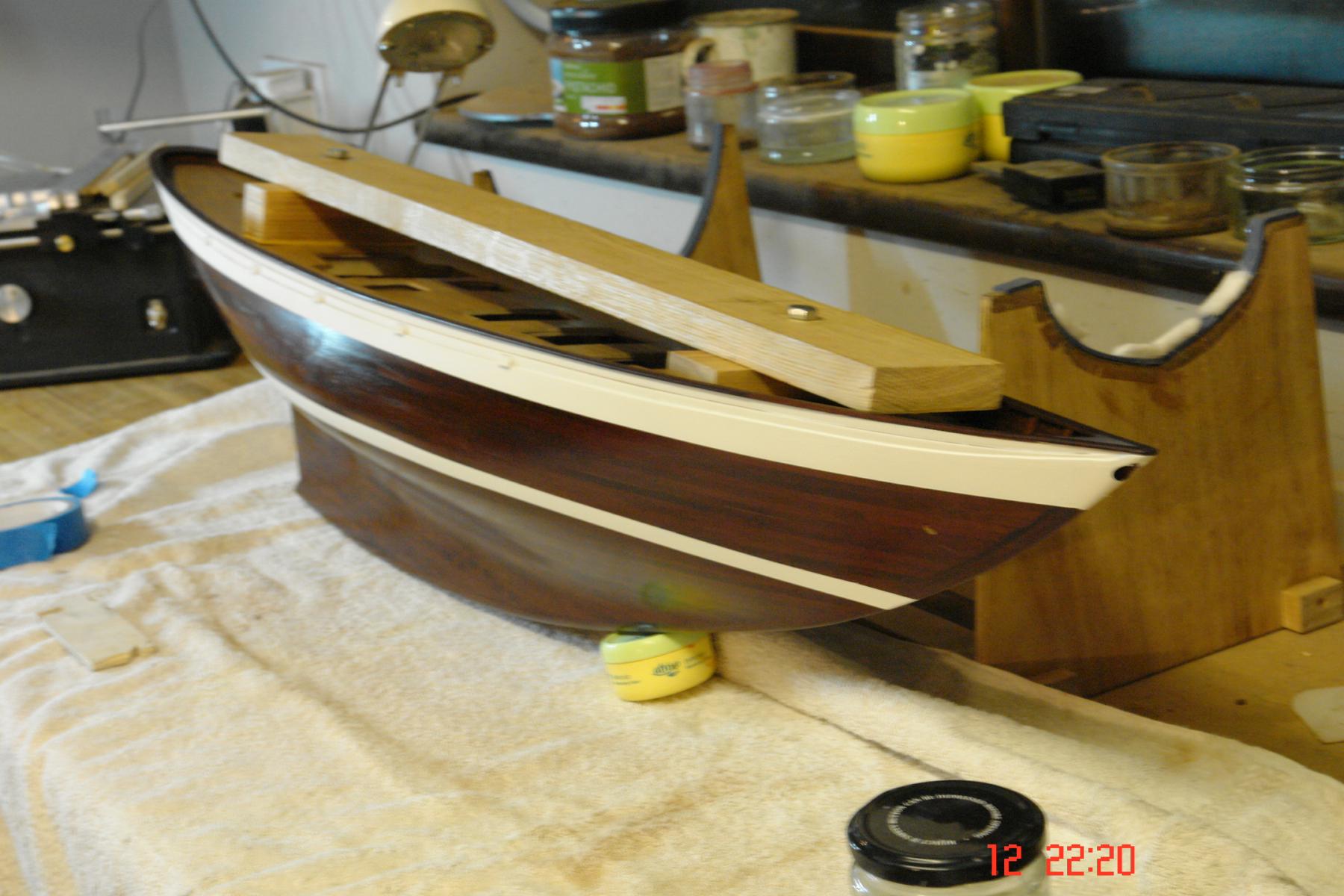
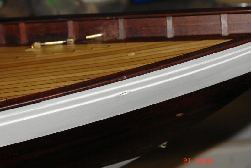
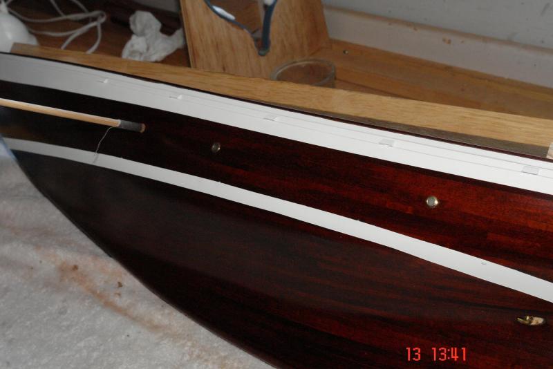
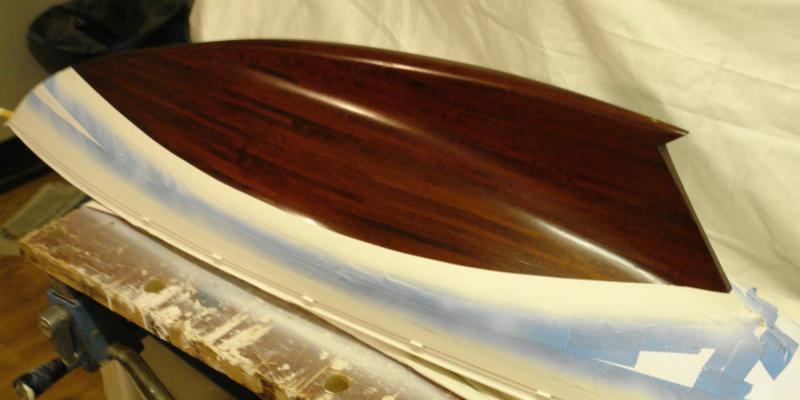
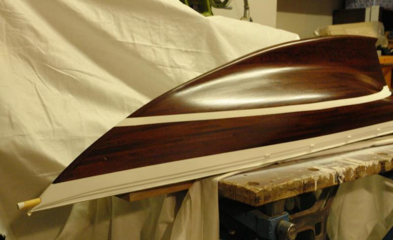
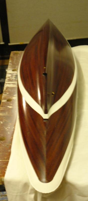
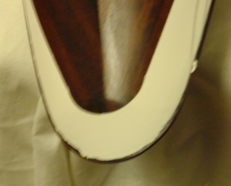
I finished airbrushing the white enamel today and being impatient to see the results I started to peel back the masking. I always find this stage a bit stressful - Will the edges be crisp? and how much bleed will have taken place? Starting with the waterline the masking was removed. Generally the result was good with one minor area near the rudder that needed a bit of attention. So far so good so I continued to remove the masking from the bulwark area. The bulwark capping rail had proven tricky to mask, particularly at the stern so I wasn't surprised to find paint bleed in this area. Fortunately a bit of scraping with a craft knife improved it. Generally the result was better than I had feared. Meanwhile another coat went on the deck fittings - only one more to go I think.


- 882 replies
-
- 12
-