KeithAug
-
Posts
3,980 -
Joined
-
Last visited
Content Type
Profiles
Forums
Gallery
Events
Everything posted by KeithAug
-
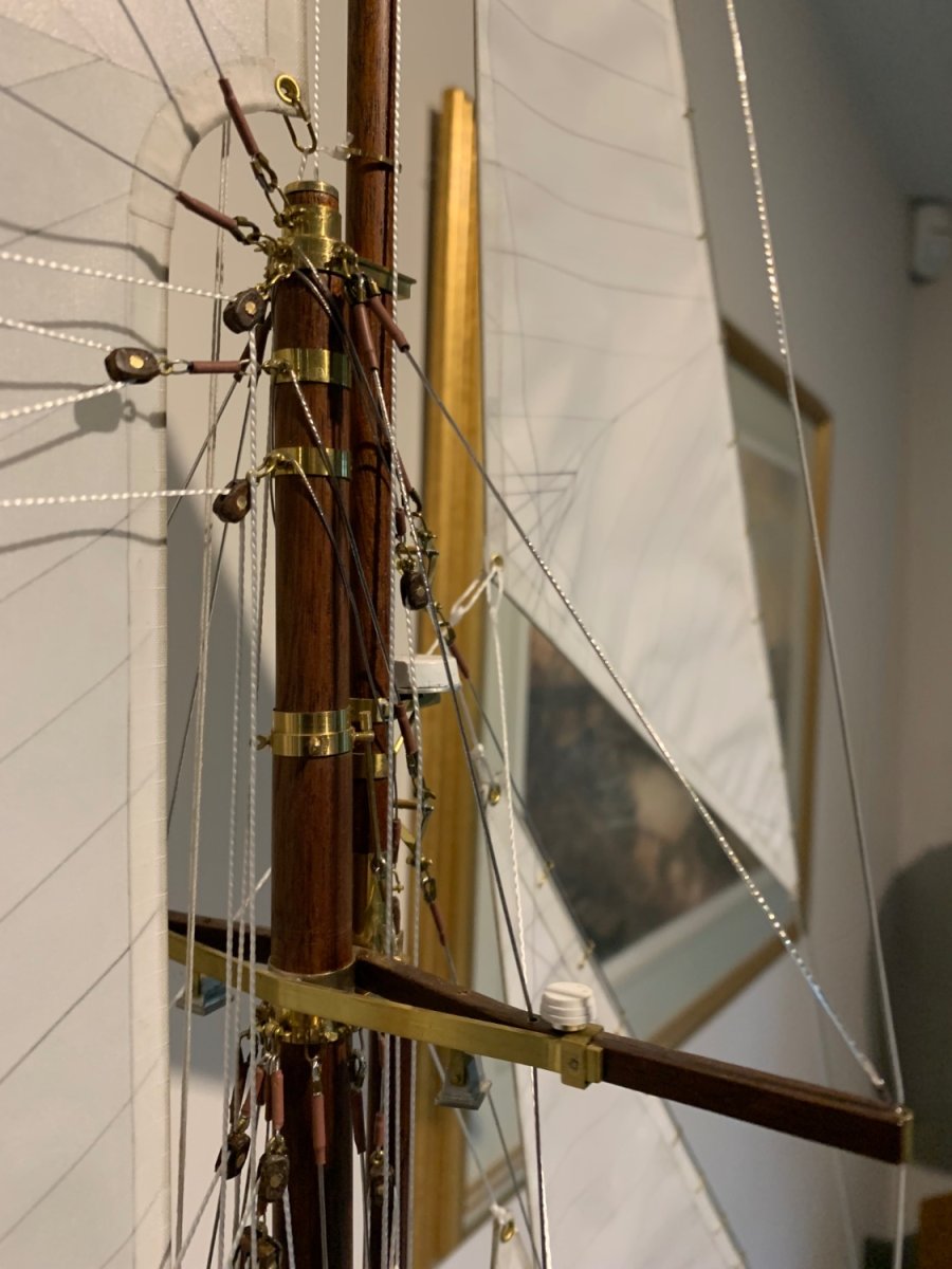
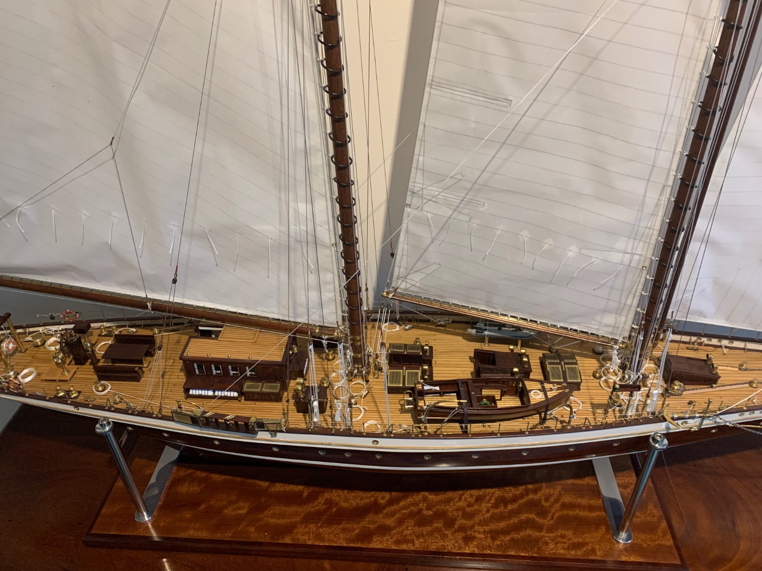
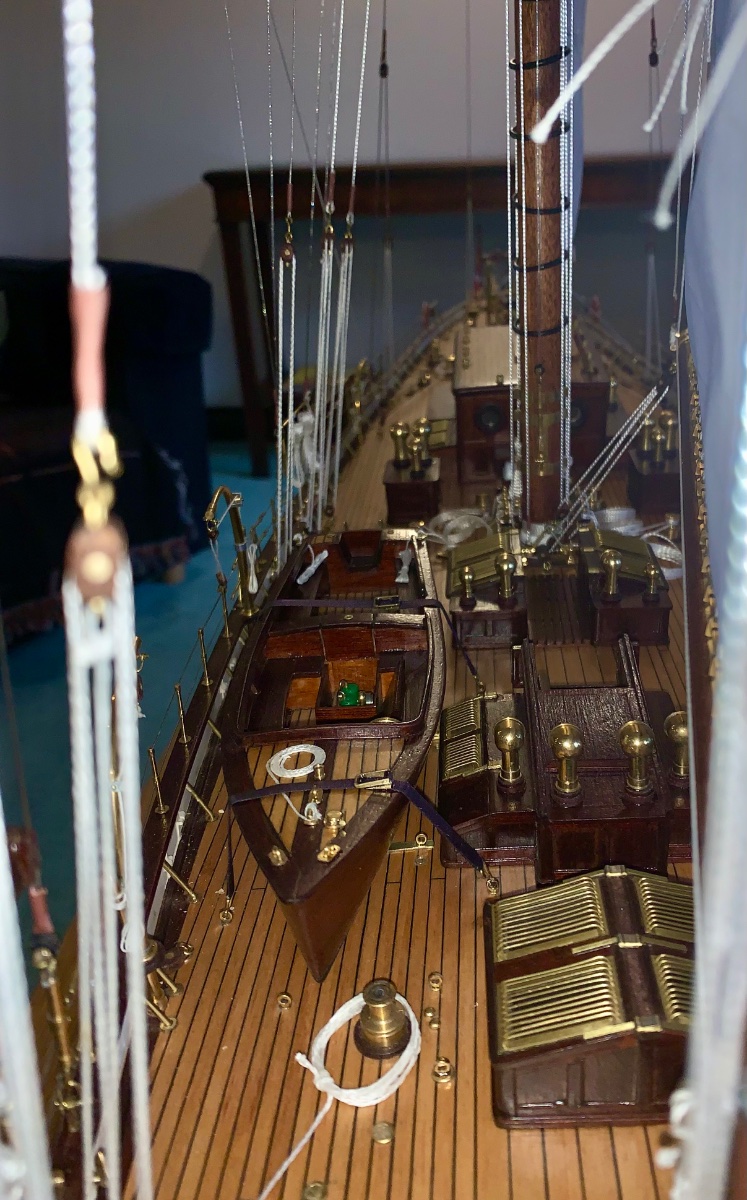
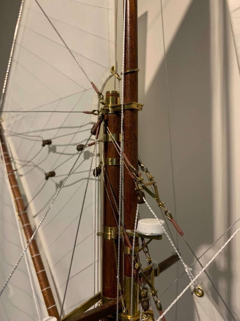
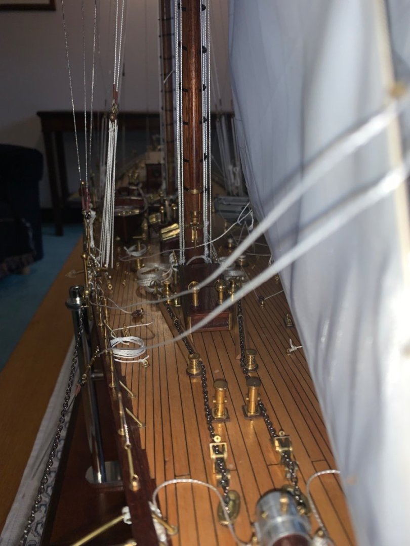
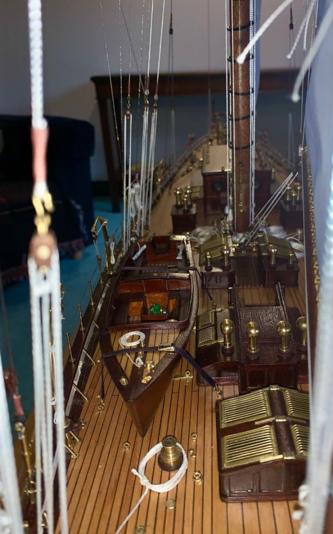
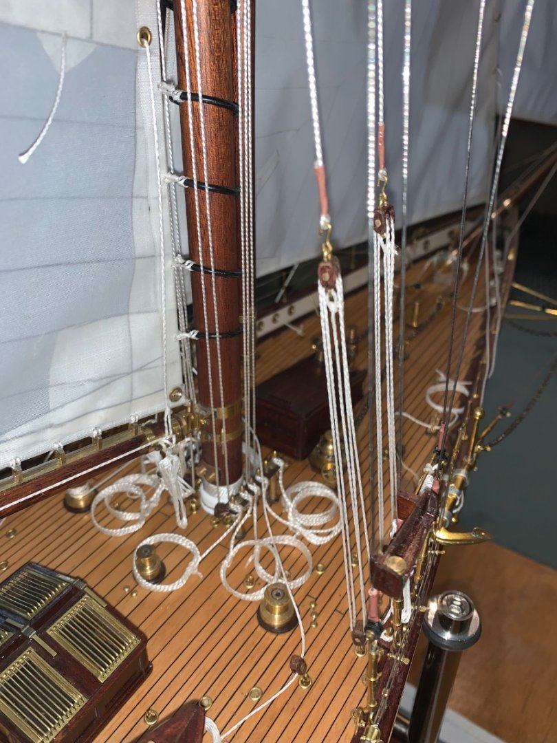
 Thank you Valeriy, Druxey, Pat, Gary and Brian. Also thanks for all there thumbs ups. The next bunch of photos:-
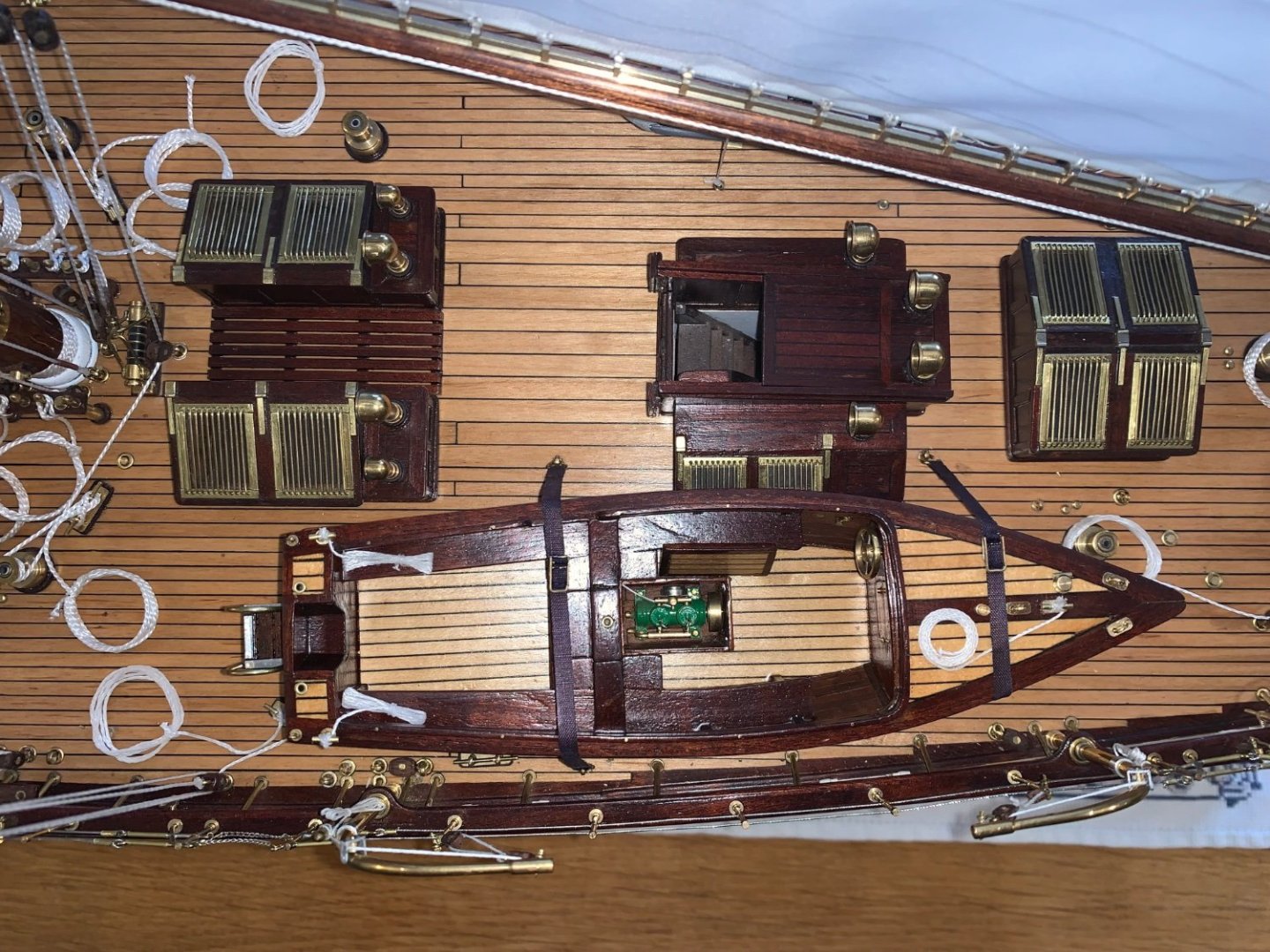


-
Zocchi - Yes - that is what i meant.
-
Wonderful woodworking skills.
-
Yes Roger. The android ancestors of the human race will be sending in their microbots to crawl over all of our creations and they will wonder why we went to so much trouble when we could have constructed them as "hard light" holograms.
-
I recall reading a book on ship modelling in which the writer commented that one should never display a photograph at a scale larger than life size. This good advice seems to be universally disregarded by MSW contributors.
-
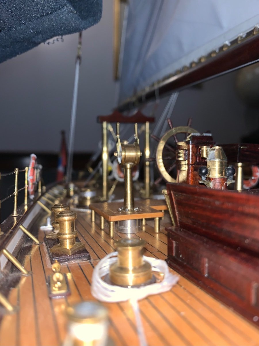
Valeriy, I had noticed that and assumed it was used for low speed manoeuvring. given the exposed position it would seem untenable to use it during action or in a seaway.
-
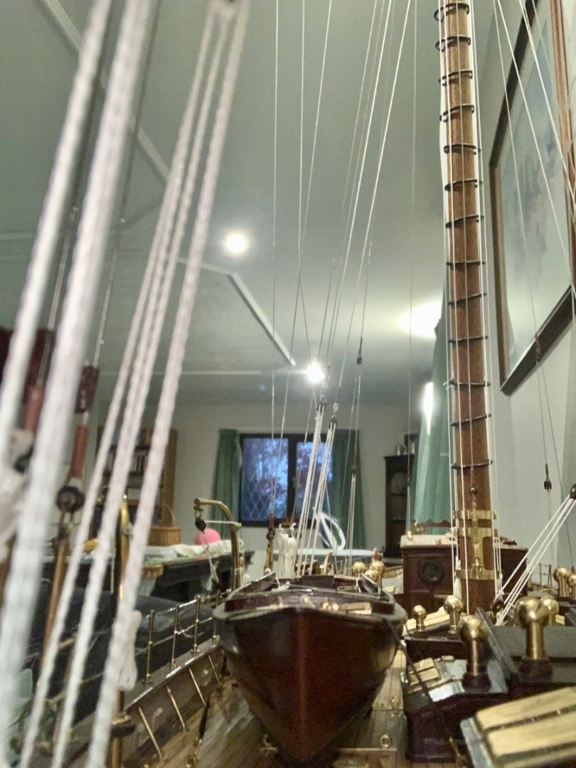
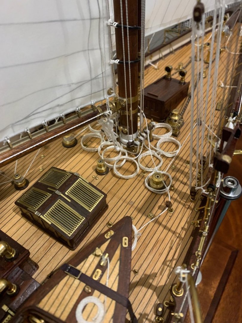
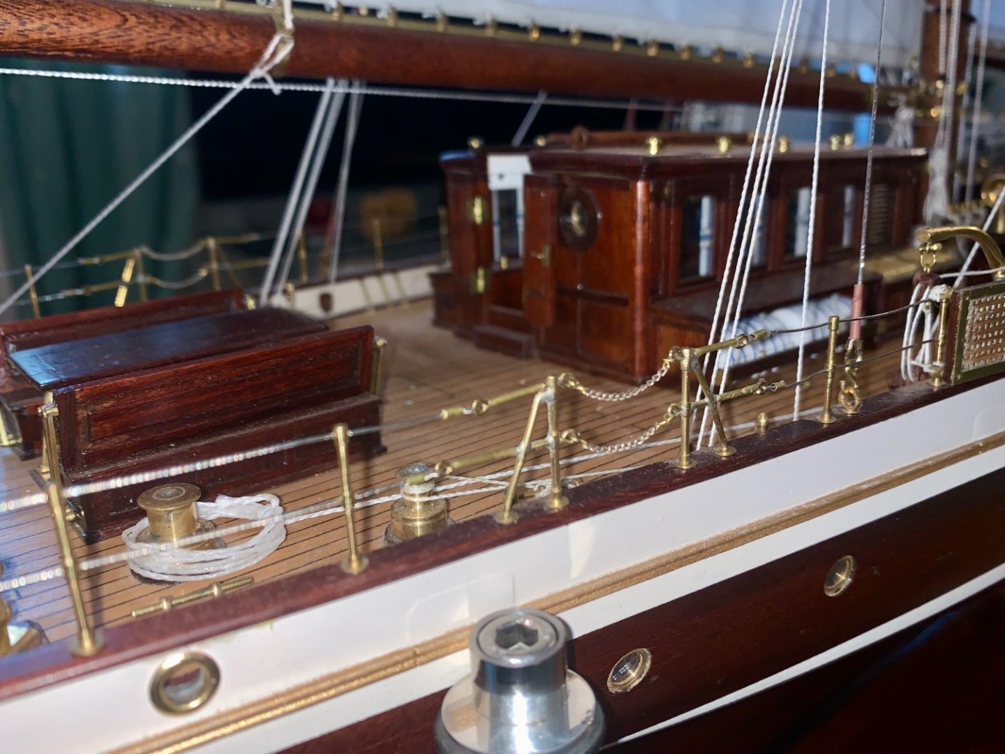
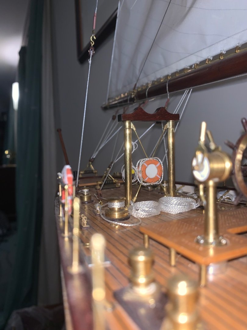
I finally got round to taking some photos so over the next few post I will publish them.


-
Eberhard - I think I had picked that up from one of your earlier comments and had assumed that in such circumstances that trining the gun would have been required. Grounding seems to be a bit of a dicey concept given the flat bottom and limited freeboard / buoyancy. I bet they had some anxious moments waiting for the suction between the hull and the mud to let go.
-
Eberhard - I have to agree with Phil that the gun is particularly magnificent. Firing the gun on the beam must have been a particularly unwelcome job for the bridge crew.
-
Impressive start Valeriy - and very quick.
-
Some of the hull lines look a little bit odd. it might just be the shading effect - is that the case?
-
Very interesting Valeriy. I would have been tempted to go for a larger scale.
-
A very interesting project. Good luck.
-
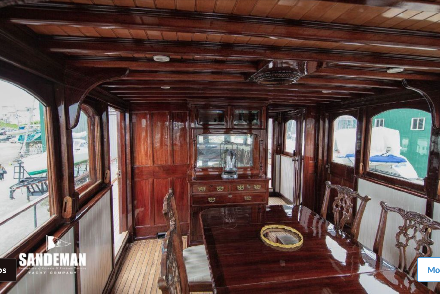
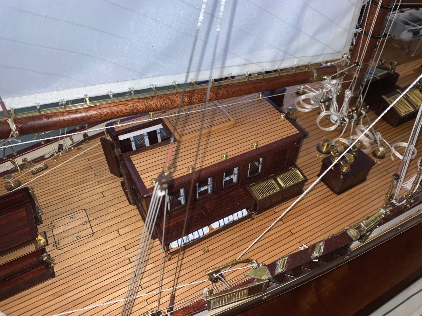
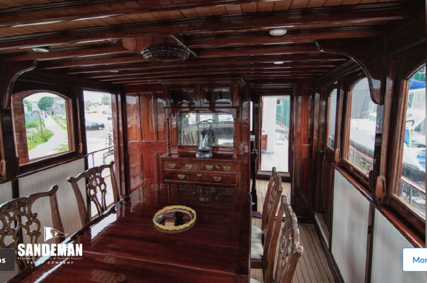
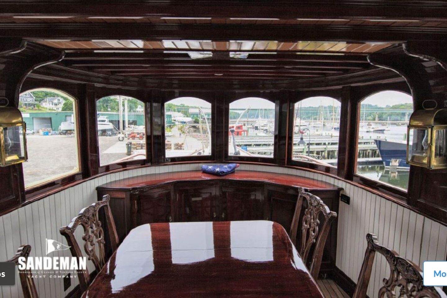
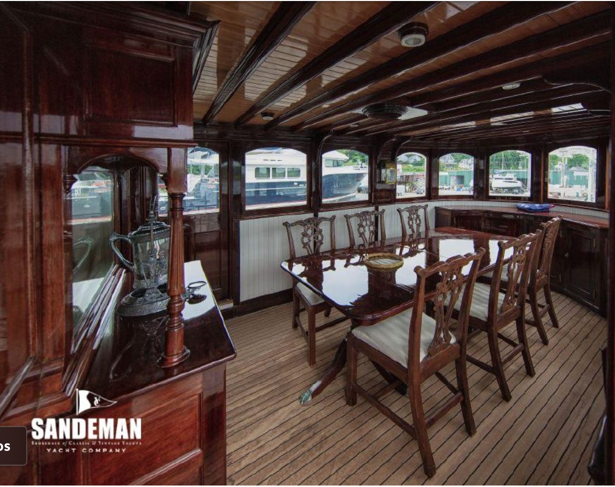
Roger - it is highly probable that your eyesight is better than mine as I need my cataracts done. Below are the 4 shots showing the internals of the main deck house. These are the only ones which show the dining table. What I think I see is a mirror behind a silver cup and above this a cabinet that may contain glassware. Are these the ones where you see a model?

-
Brian I am never very sure about MDF but i suppose for display models it is both cost effective and stable. I suppose i am too set in my ways. I need to get out more! I agree with bob re slow progress. Seems really quite fast to me.
-
Ras - Thank you for explaining. I was aware that in some photos the sponsons were not obvious. What you say about recoil makes a lot of sense.
-
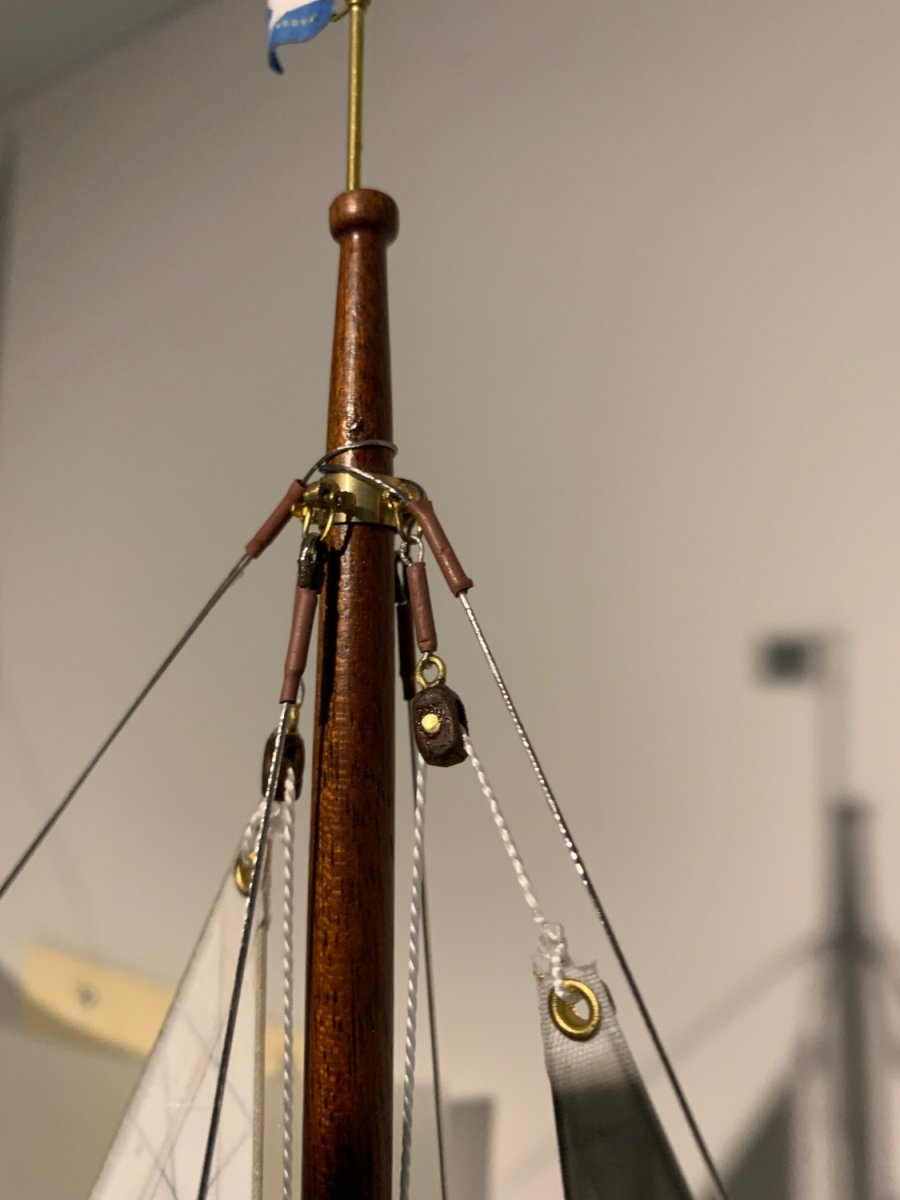
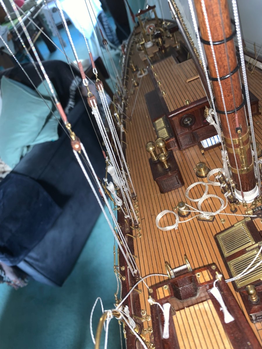
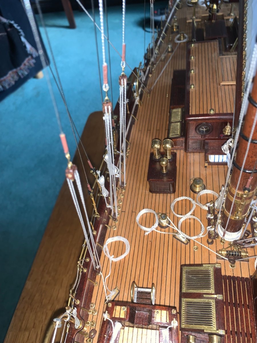
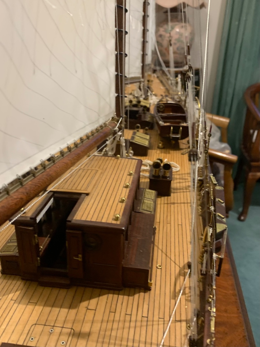
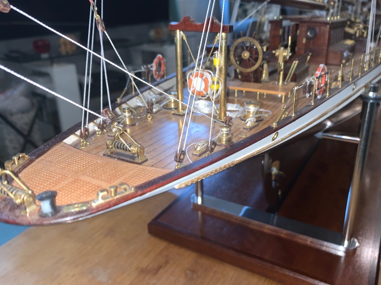
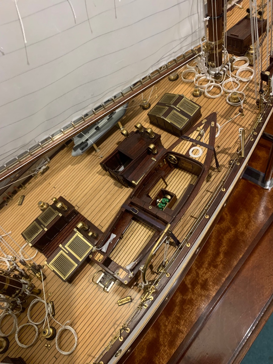
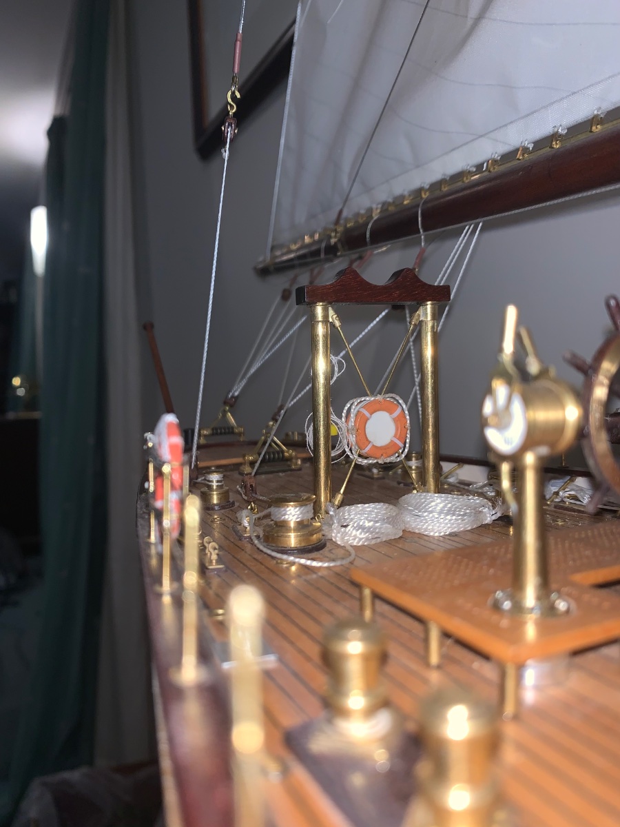
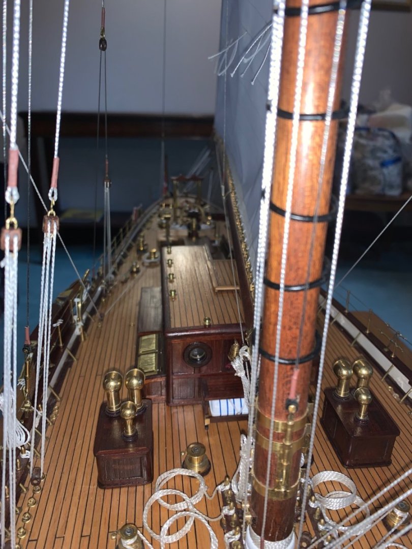
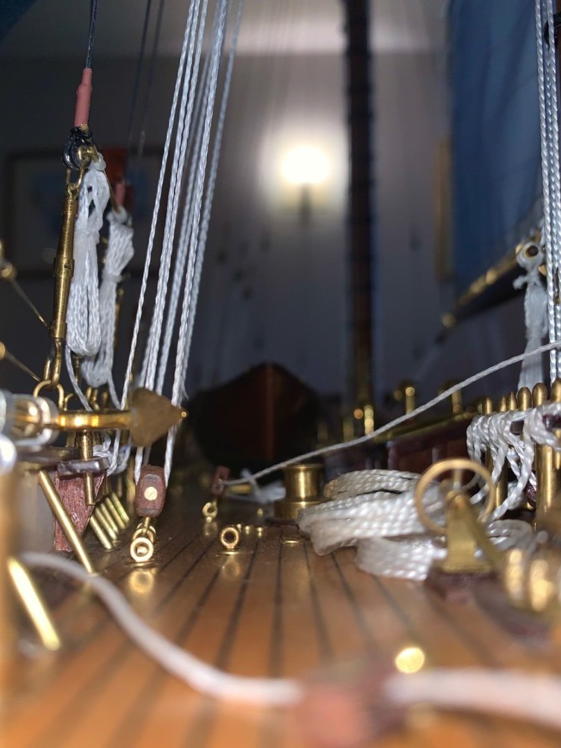
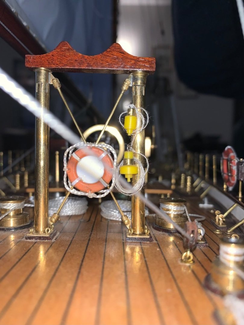
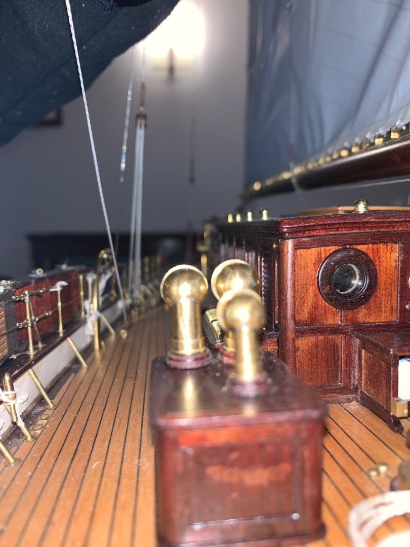
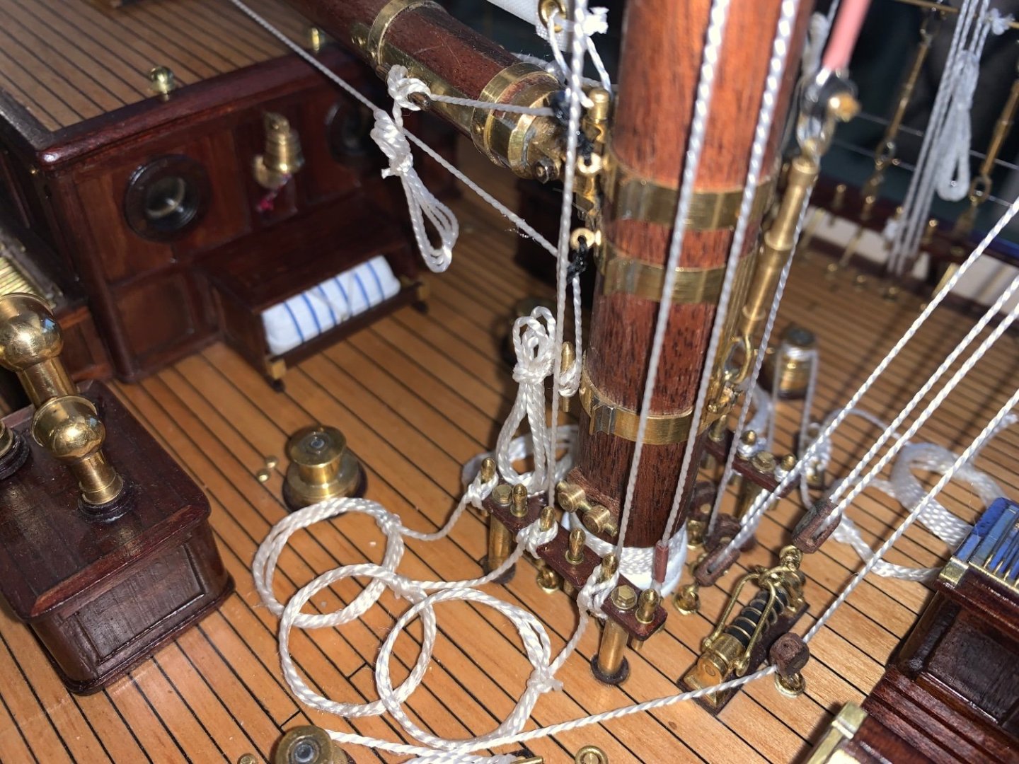
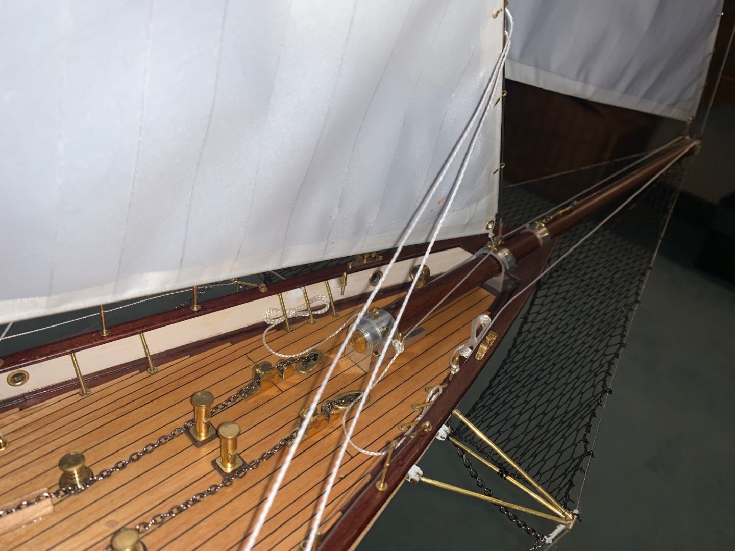
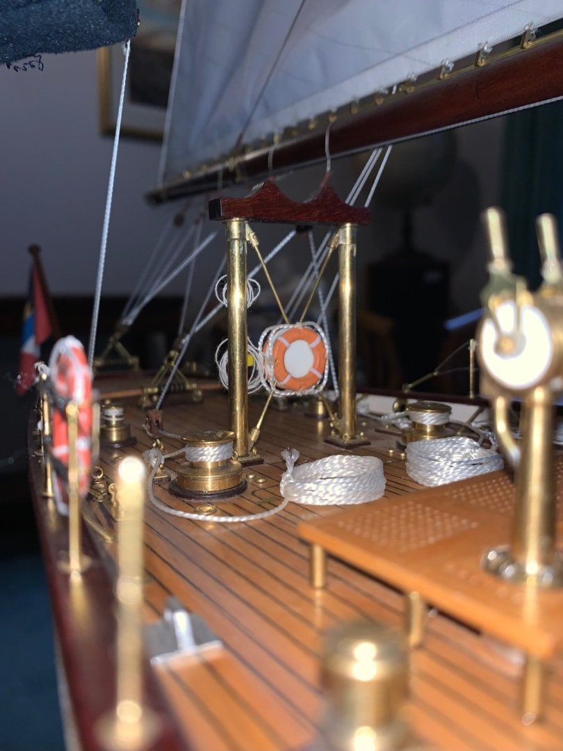
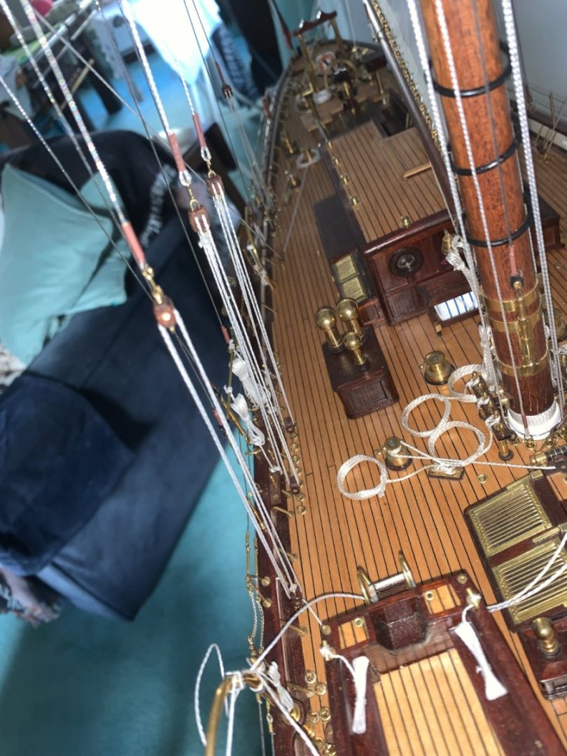
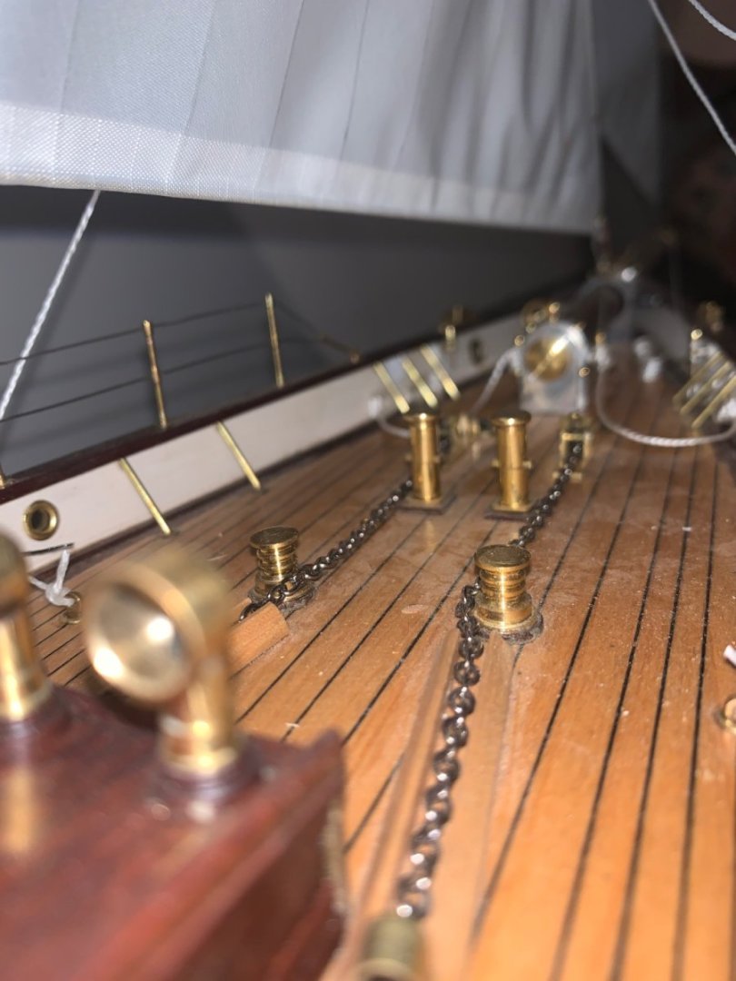
Bob, I sent a few shots of Germania to Jeff Rutherford when I asked for some information and I promised to send him the link to the build log once I started it. I haven't made contact with Mr McNeil. I am not sure that he would be interested in seeing a model when he owns the real thing - lucky man. I really need to get on with the photos before this log morphs into a Cangarda build log. Here are a few pre cleaning photos to get the build log back on track before I do the cleaning.


-
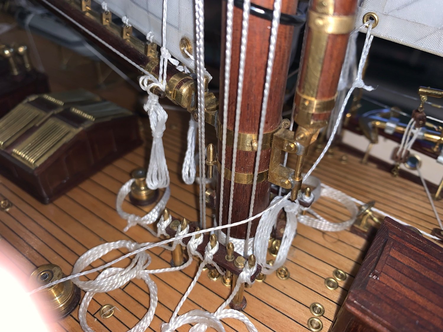
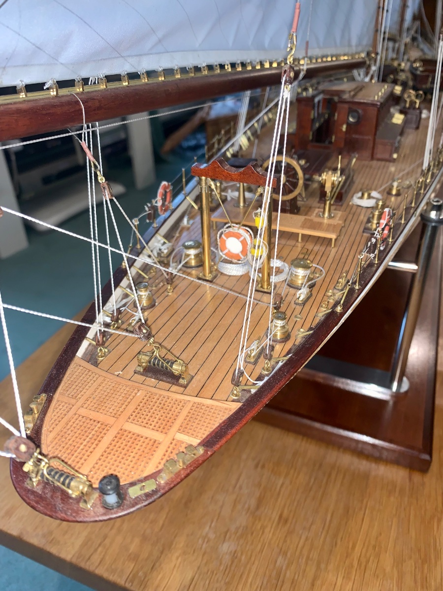
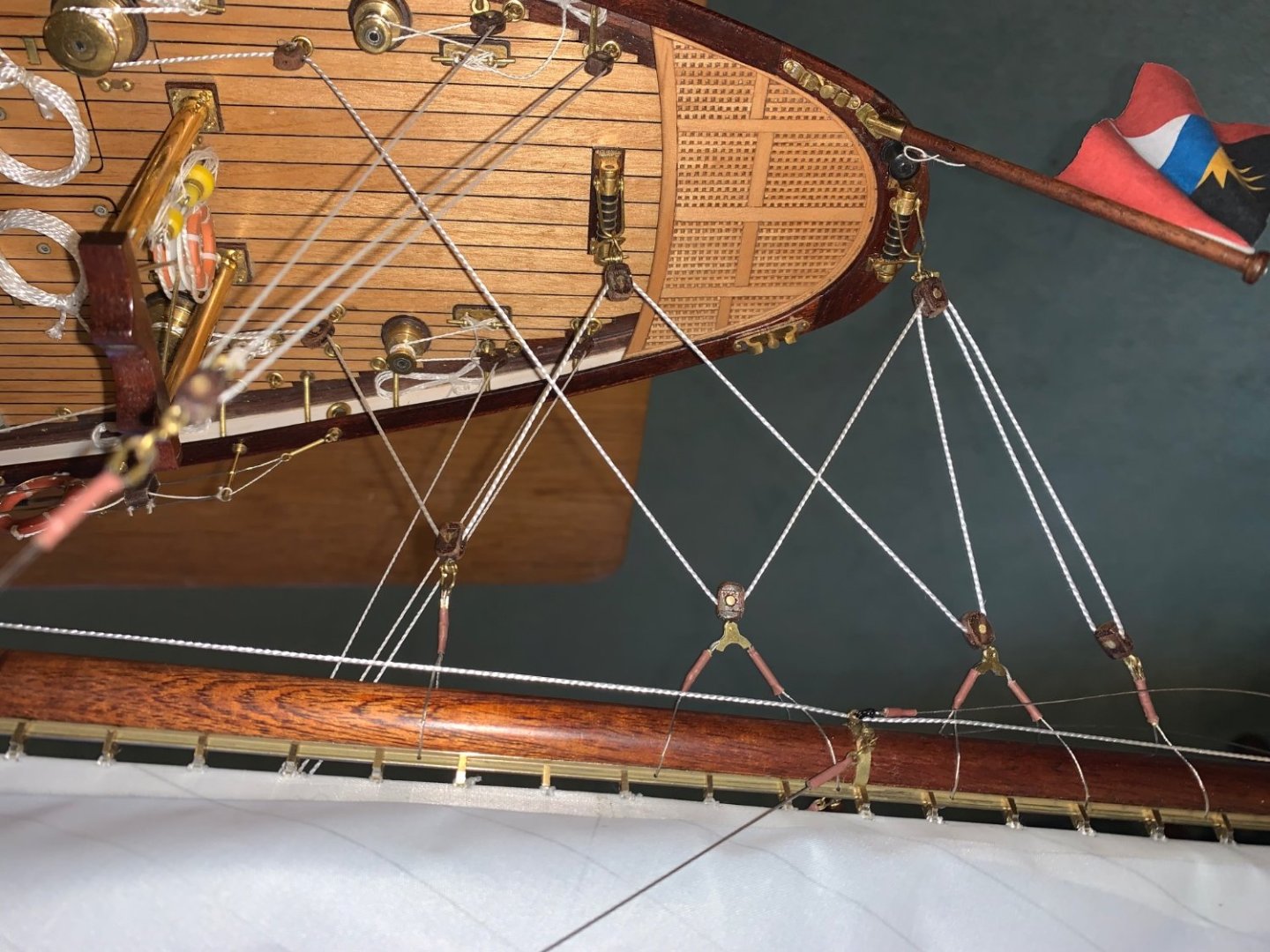
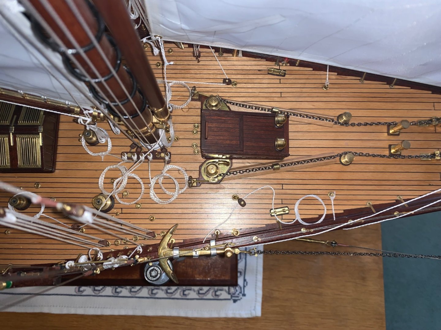
Rick Thank you - very much appreciated - that would be fantastic. It is a comprehensive set of photos looking down on the deck showing the attachment points for all the stays / blocks plus the deck planking detailing around the deck houses / skylights etc, that I need. It is going to be a a year or more before I get to that part of the build so no need to rush out with the camera. Best regards,
-
USS Cairo by Zetec - FINISHED - 1/50 scale
KeithAug replied to Zetec's topic in - Build logs for subjects built 1851 - 1900
Heroic task. -
Value-for-Money Airbrush
KeithAug replied to BANYAN's topic in Painting, finishing and weathering products and techniques
Pat, Sorry but i have only just seen this. I bought a compressor with 2 airbrush pack and to be fair the airbrushes looked well made. It cost about £90 for the whole package. The airbrushes lasted about 18 months of very limited use - probably 10 to 15 times for each brush. I didn't really regret getting them because it was my first experience of air brushing. When it came to replacement I bought an Iwata Neo which cost £60 and it has lasted somewhat better. it is now about 5 years old and still going strong - but again not heavily used. I note the Neo is now about £100. Hope this helps. -
Tom, yes I have got that one. Bob I have made contact with Jeff who has been very helpful, I just don't want to push my luck by placing too big a demanding of his resources.
-
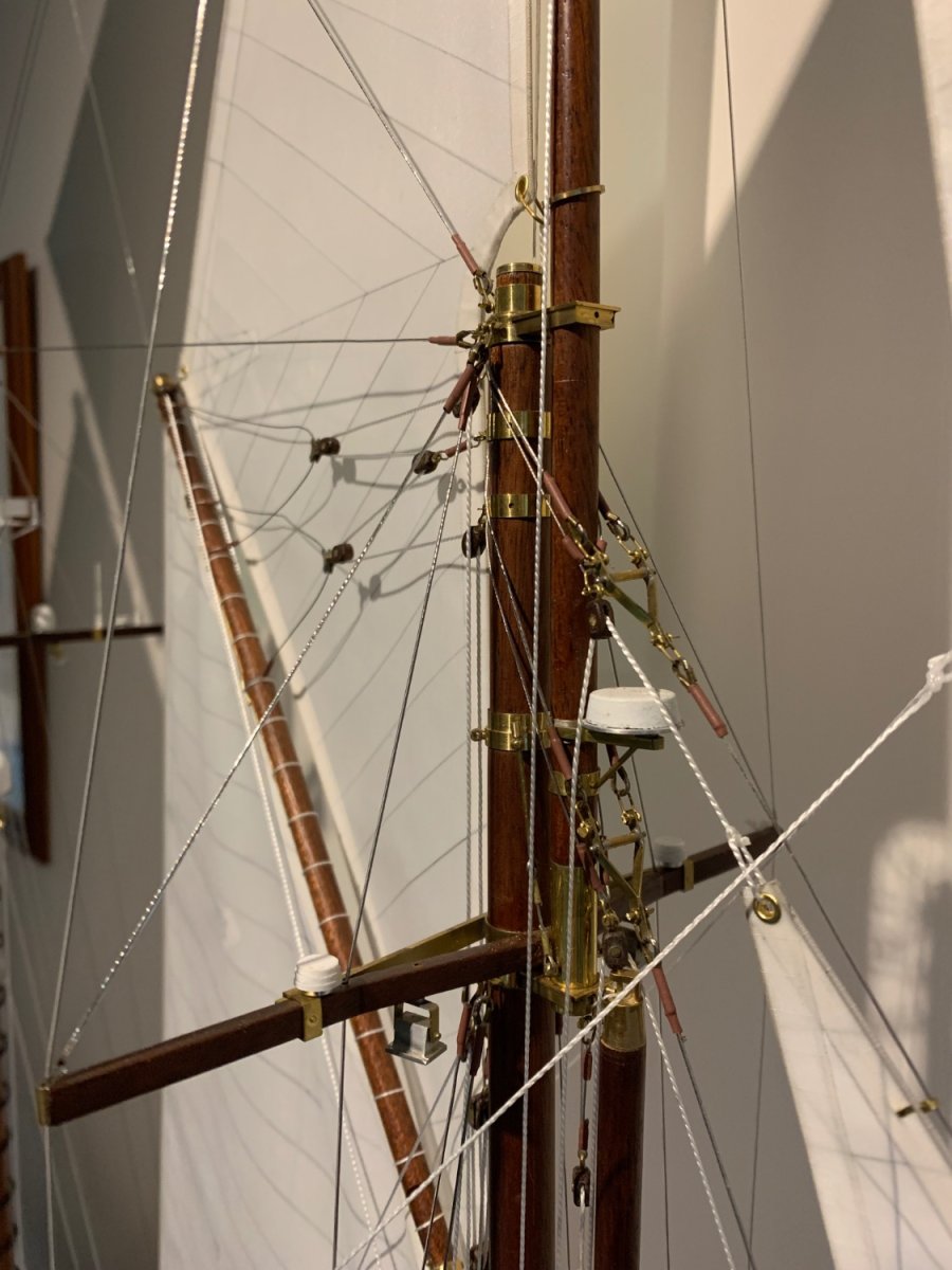
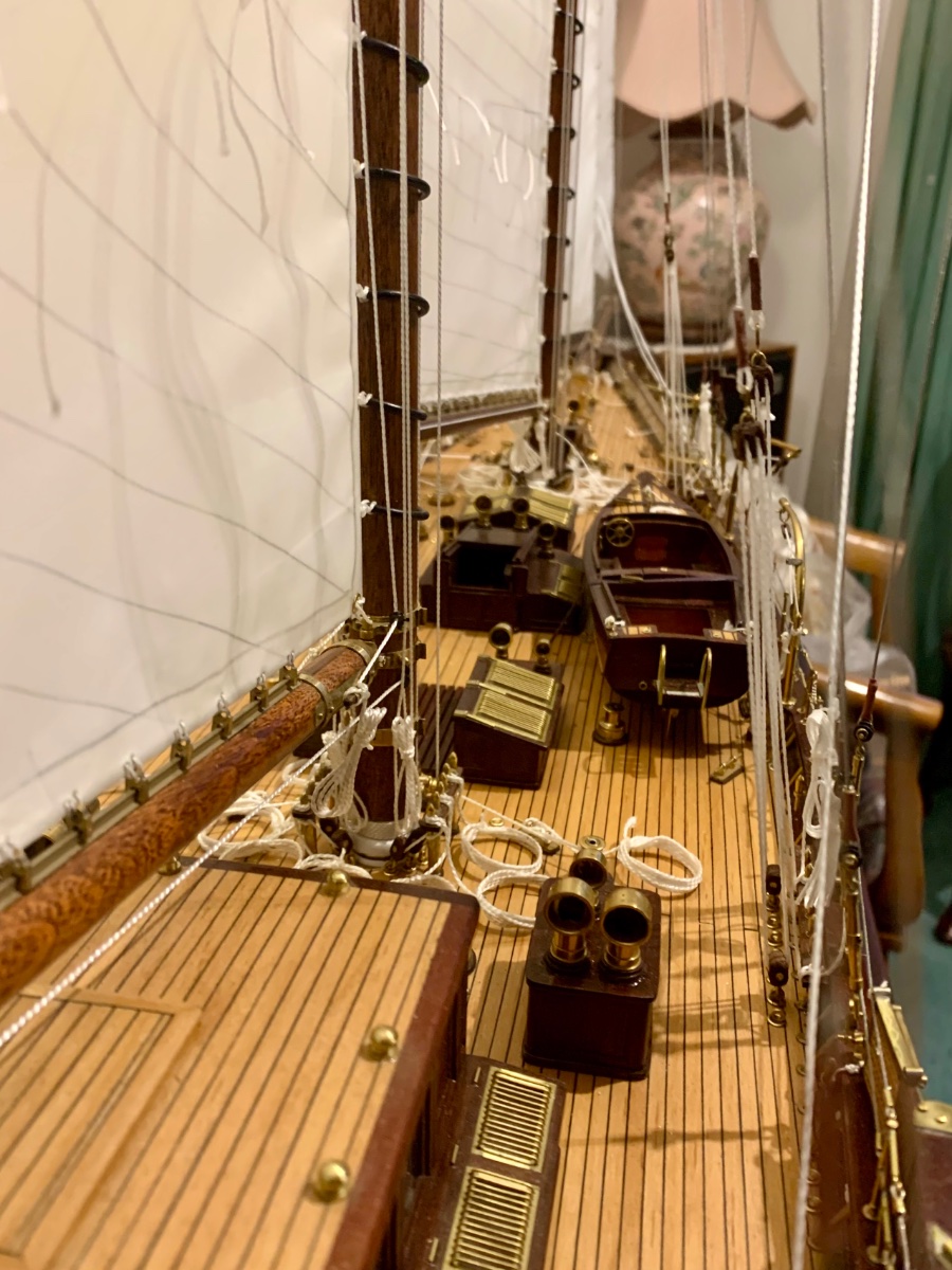
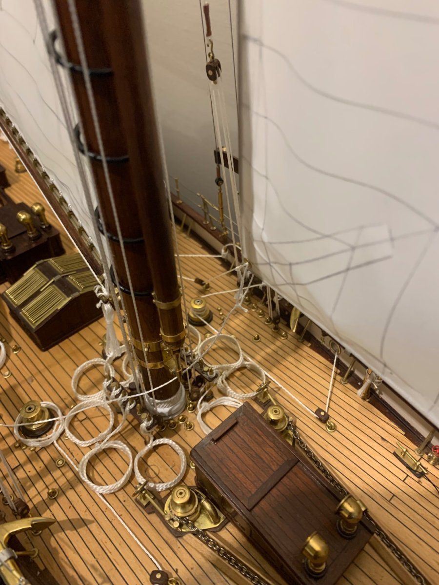
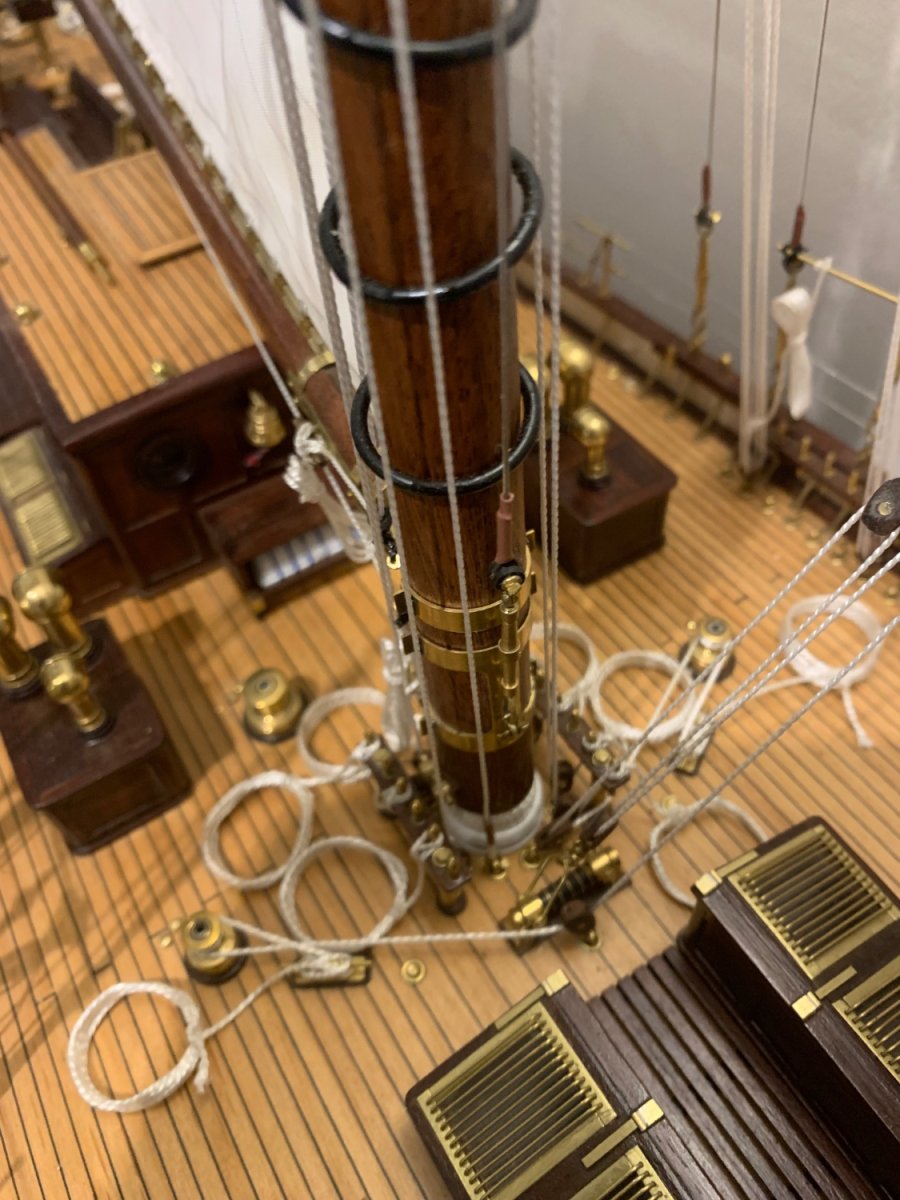
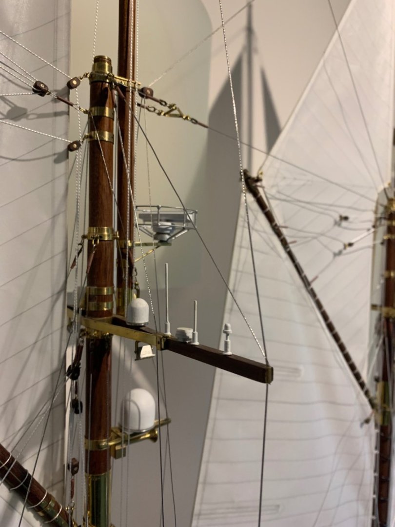
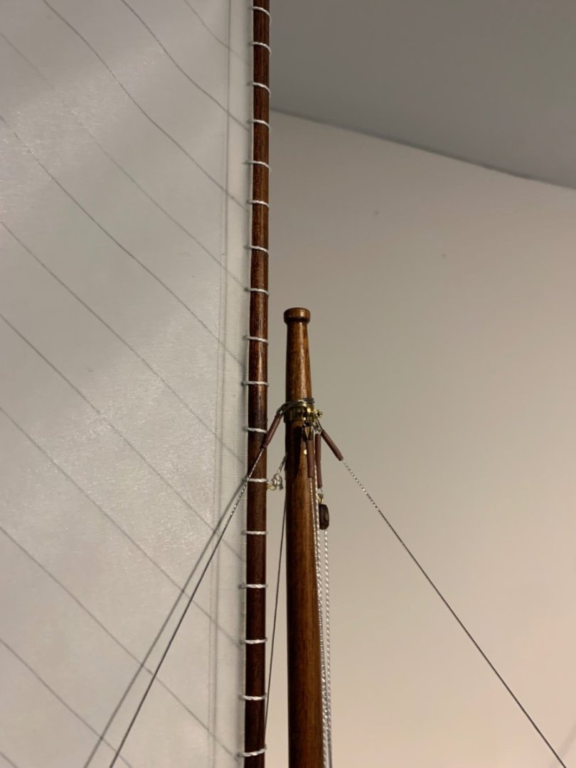
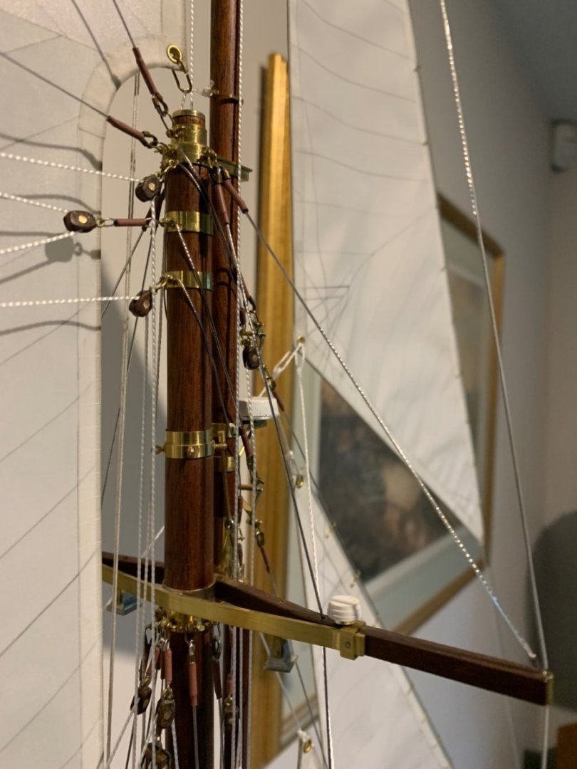
Bob - many years ago I built a pond model which in the end I never sailed because I was wary of it getting damaged. Ever since I have focused on display models. I am planning to represent some of the engine room and other below deck areas in so far as as they can be seen through the skylights. One of the reasons for considering the 1:24 scale is that I can do a much more accurate job of the deck house interiors. The deck and rigging complication is that they are the areas where I have the minimum of detail. In due course I may be putting out a plea to MSW members for any photographs they may have.