KeithAug
-
Posts
3,986 -
Joined
-
Last visited
Content Type
Profiles
Forums
Gallery
Events
Everything posted by KeithAug
-
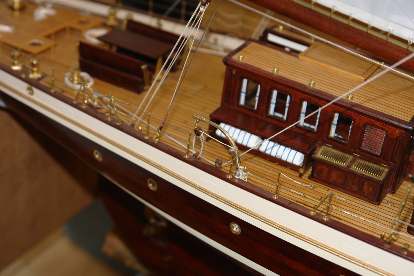
 Ras - nice job on the lockers. I particularly like the cup holder for the six pack of lager to the starboard side of the steering position.
 -
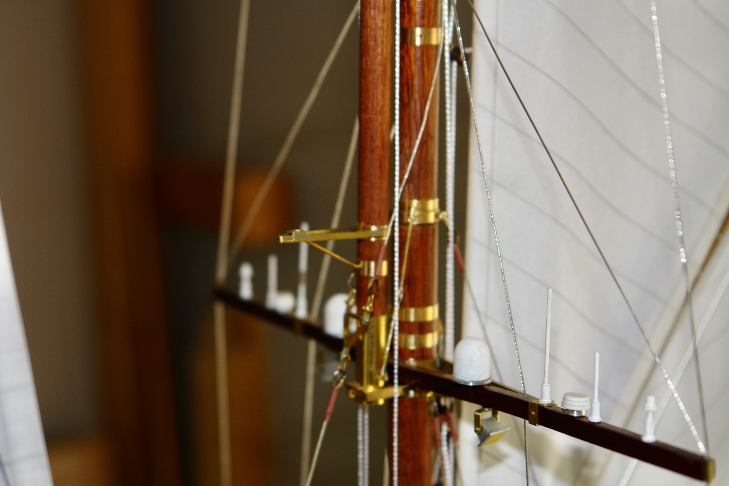
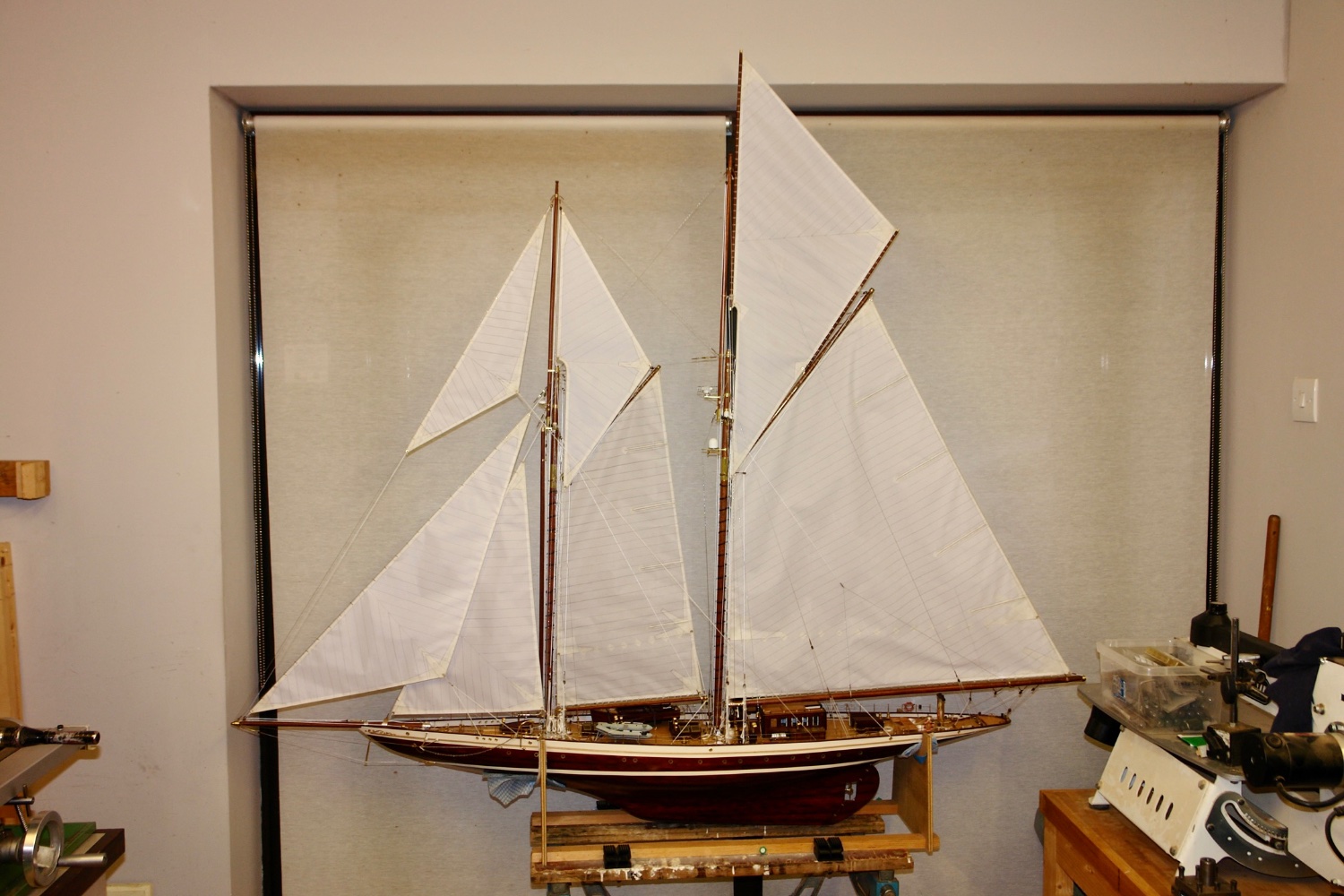
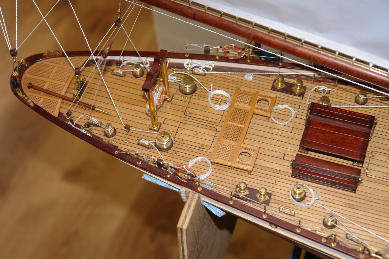
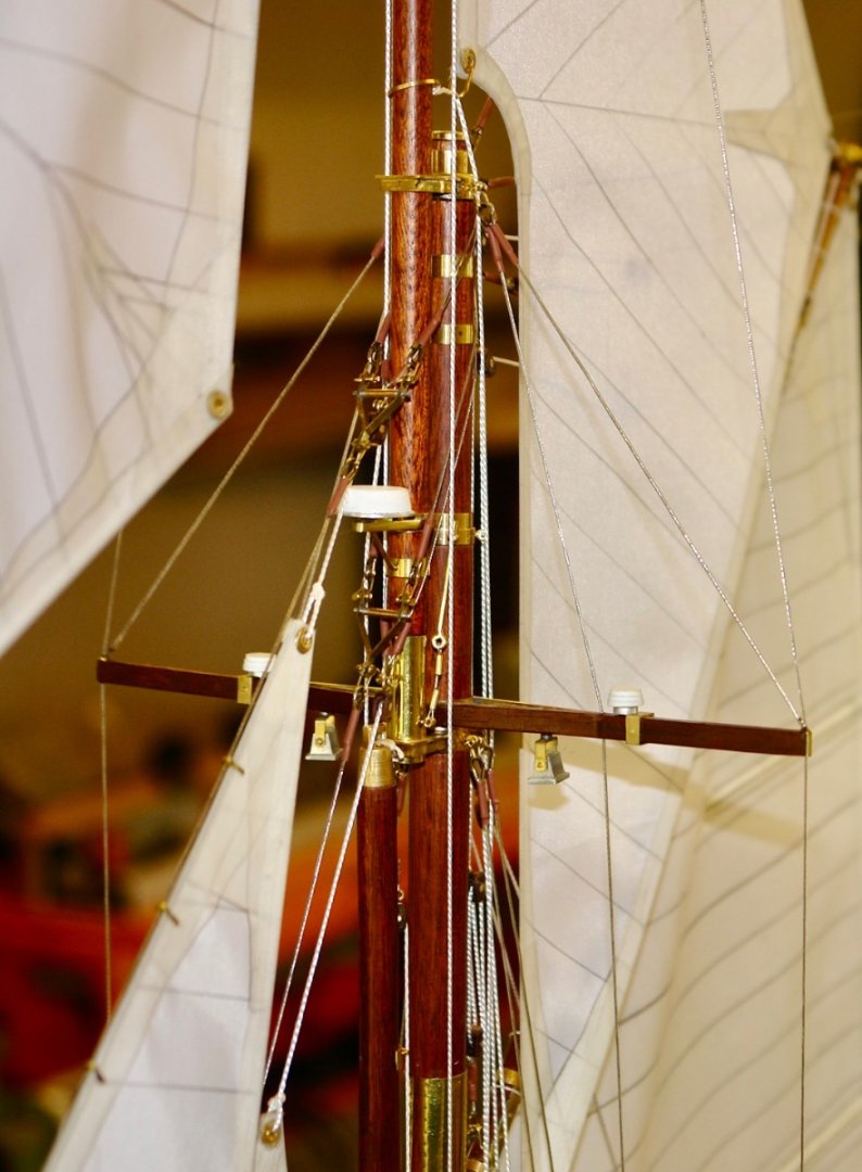
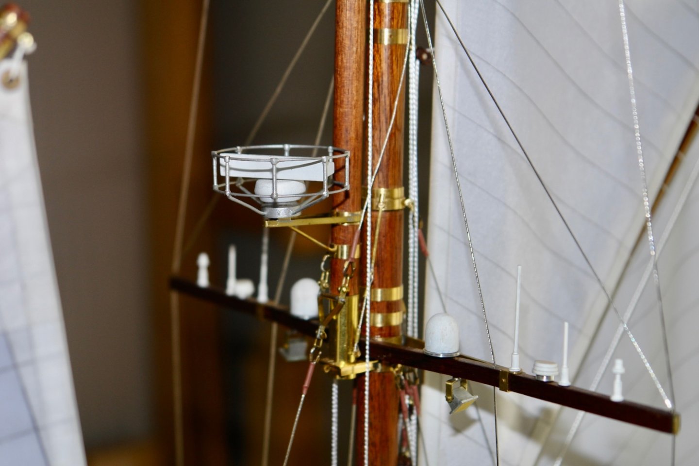
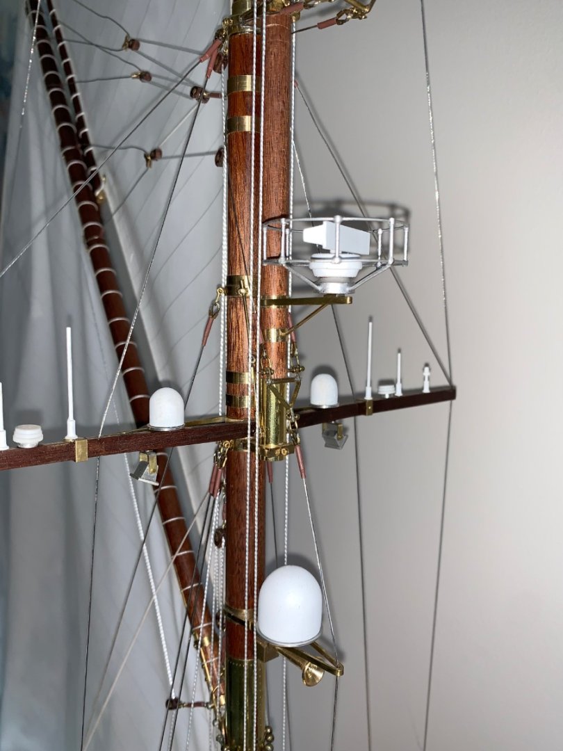
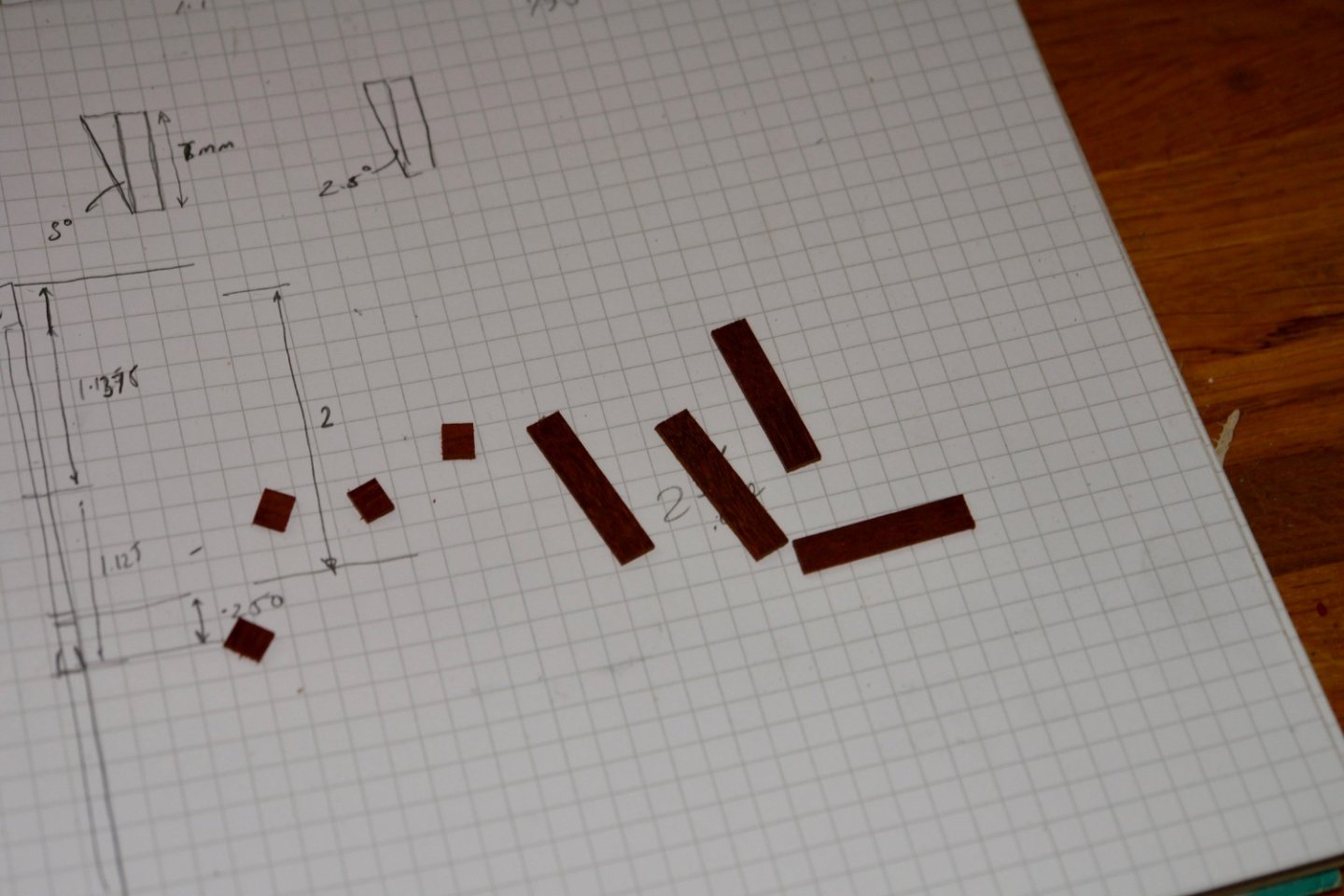
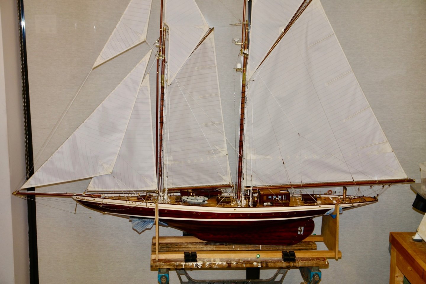
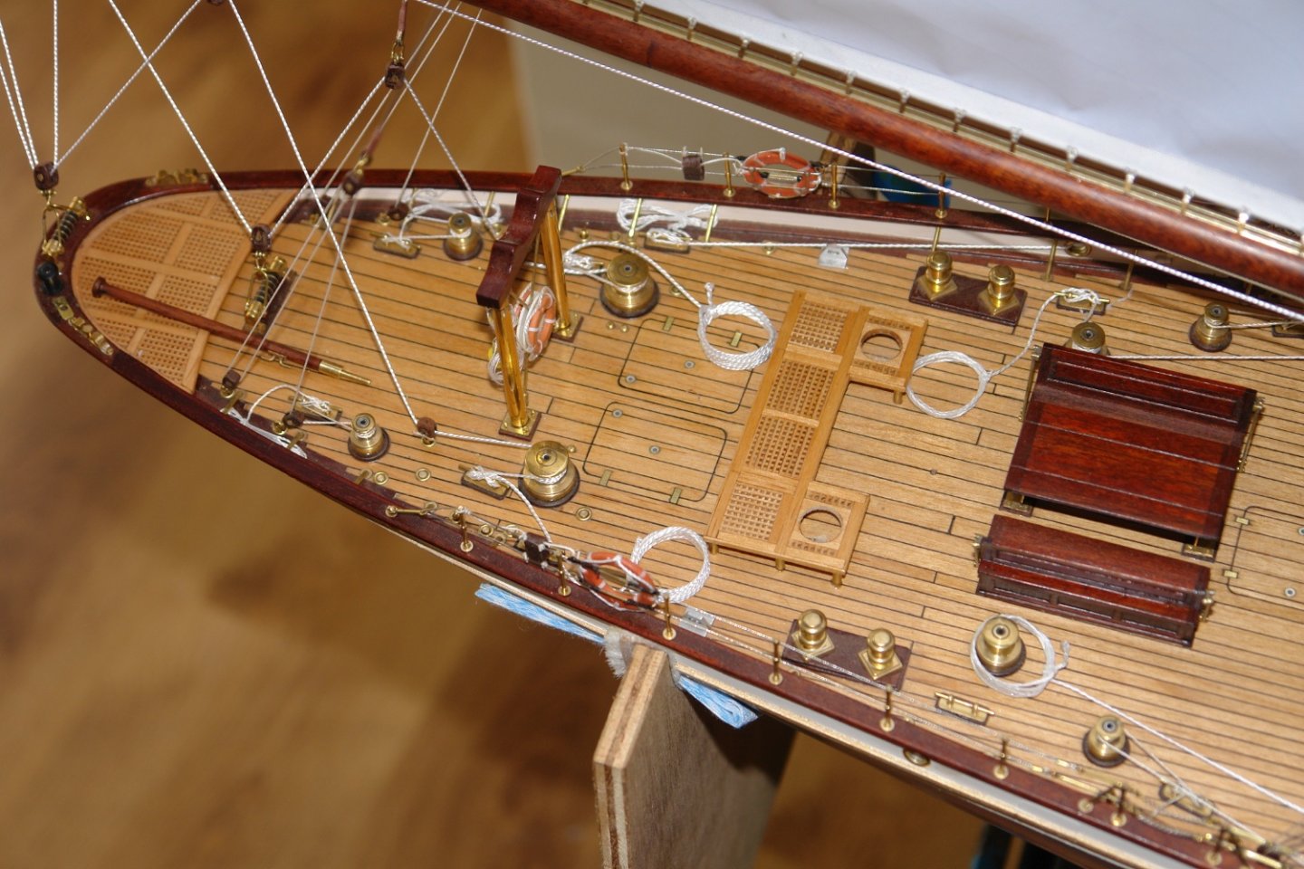
Thank you to everyone who has commented upon and / or liked my work. Firstly a bit of catching up with the upper ends of the masts. The lower foremast showing the crosstree and the shrouds. The mainmast crosstree and shrouds prior to mounting the radar. The small job of gluing on the previously made radar was completed. $ The mountings for the port and starboard navigation lights were made from .040" thick mahogany. Painted brass lights were then made and fitted. I still have a few things to do but it is now typically 2 to 3 deg c in the workshop so the model is going to be moved into the family room for completion. Here are the final 2 shots of Germania in the workshop.


-
Hermann - they were just a set I picked up through a google search. i have had a look but can't find the exact ones but these are very similar. https://www.aquamaremarine.com/uk/product/quick-release-pad-eye-ratchet-strap-kit-5-4m/
-
Druxey - noted ! will follow your advice. Veszett - it is steel - it is quite heavy so it should be ok. What a coincidence Chris. Dogs and Grandchildren are a delight.
-
The book "Jolie Brise - A Tall Ship's Tale" by Robin Bryer shows line drawing of the hull of the Jolie Brise taken off the actual hull in the 1926 by Jack Laurent Giles.
- 15 replies
-
- 1
-

-
- jolie brise
- pilot
- (and 1 more)
-
Mark - Thank you but I recall a story on MSW ( I think by Patrick of Omega fame) about a model yacht that was lost on its maiden voyage. Fingers crossed that she keeps it for some time as a memory of “ Grandi’.
-
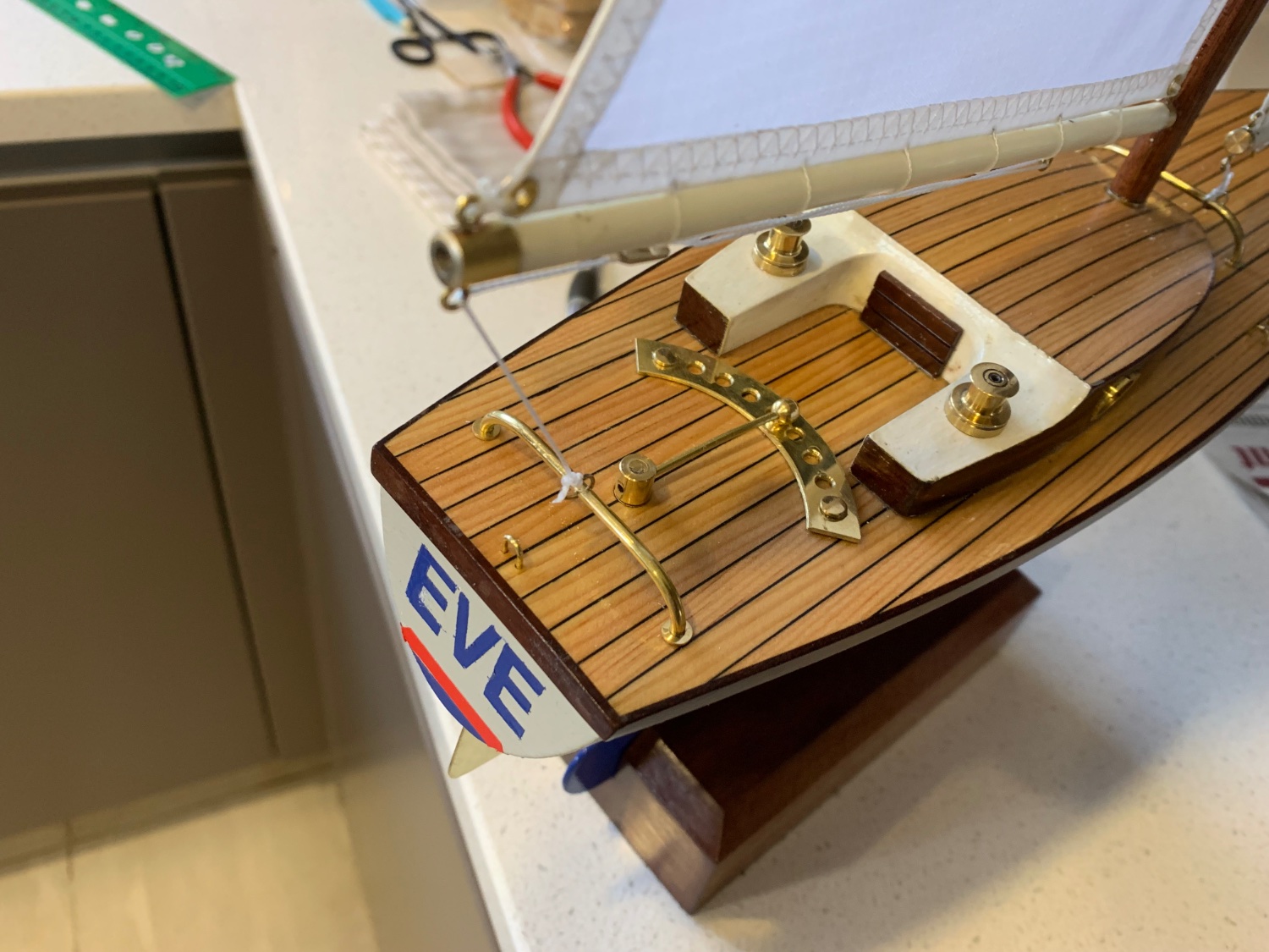
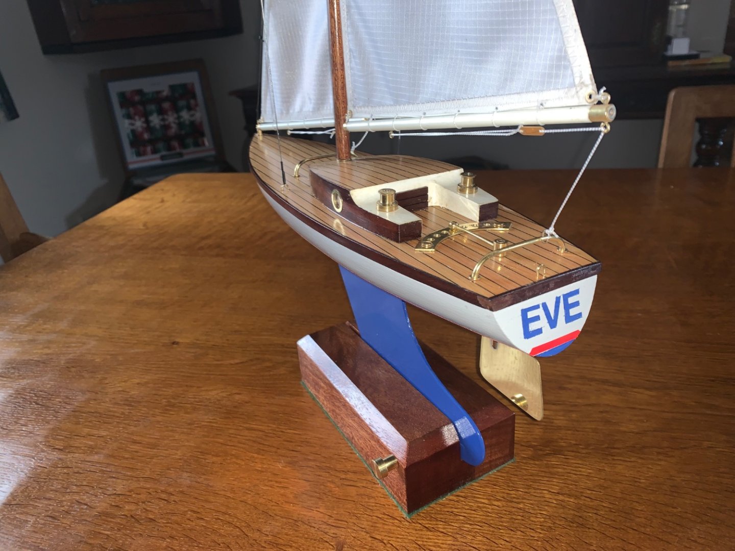
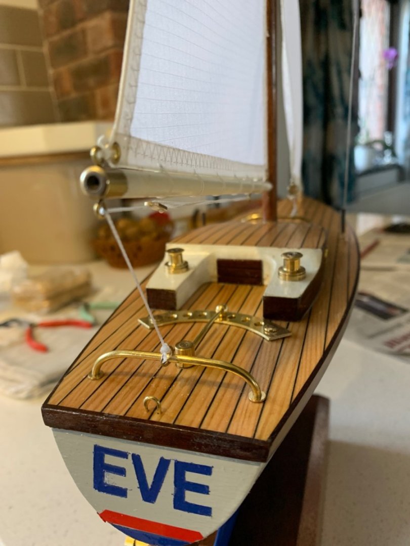
Tom. Beans Christian name is Eve. Her mother started referring to her as “my little bean” when she was about 2 months old and the rest of the family have called her Bean ever since. Mark yes I will - probably CA Tom, yes the winches arose from a discrepancy between Germanias deck plan and photographs. Andy Mark Pat Tom and Brian - thank you all for taking time to comment.
-
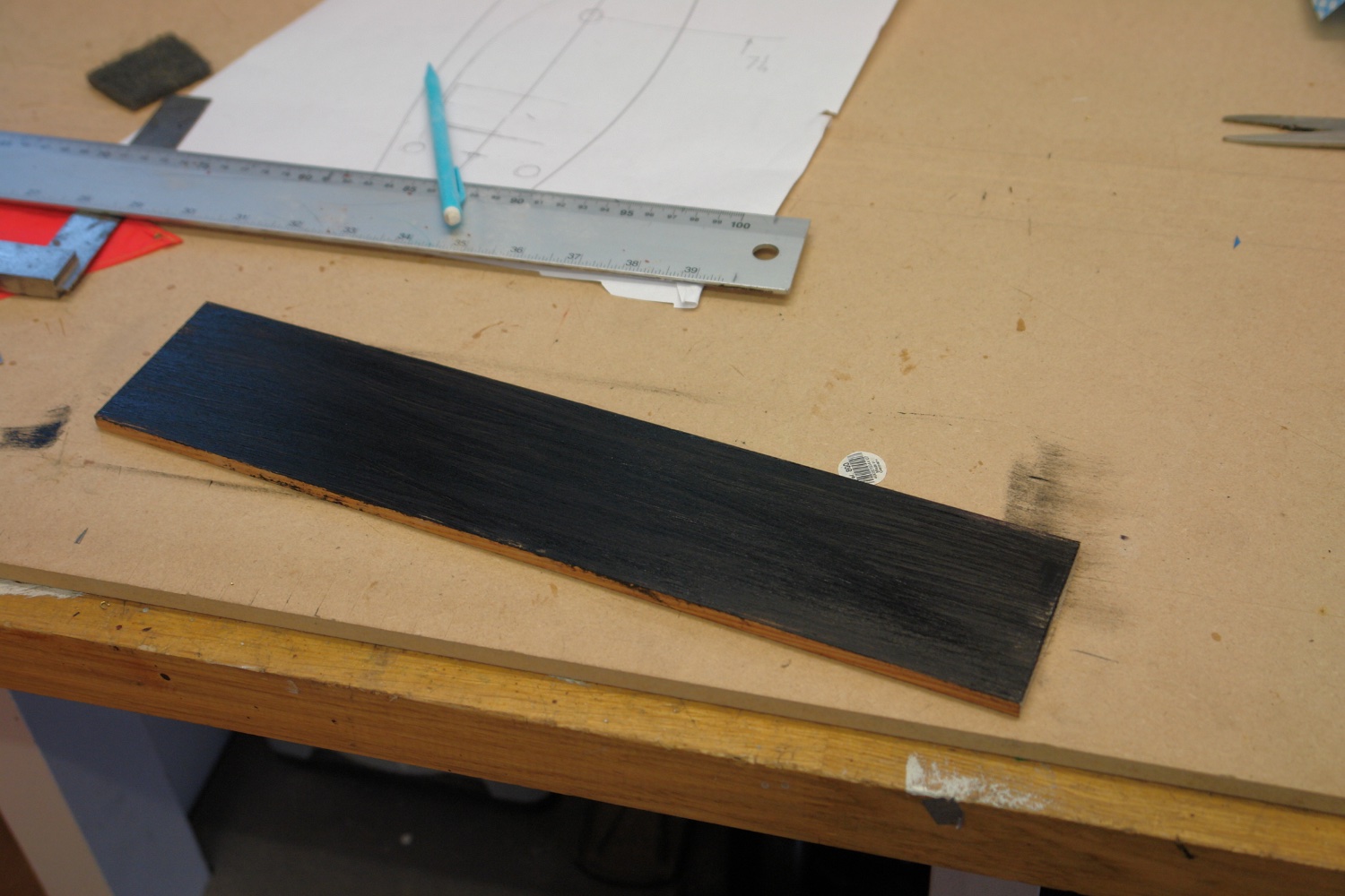
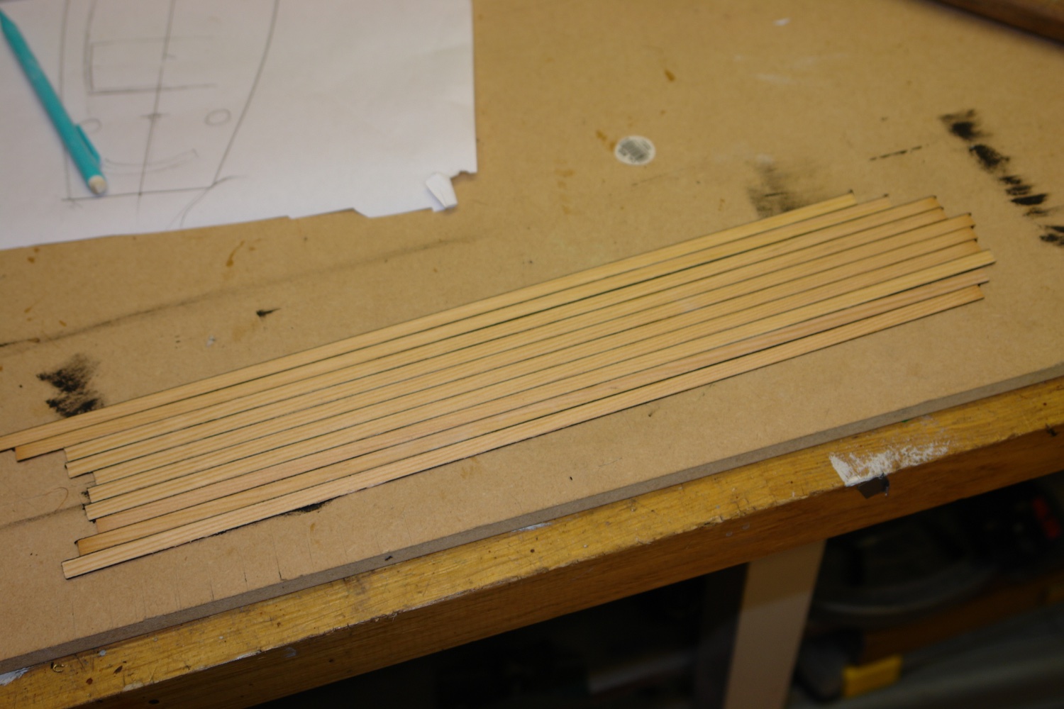
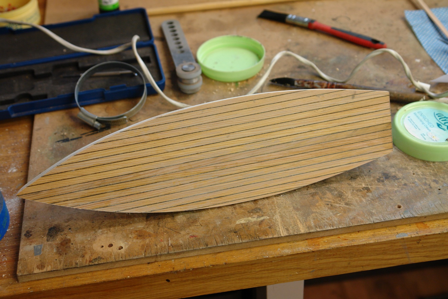
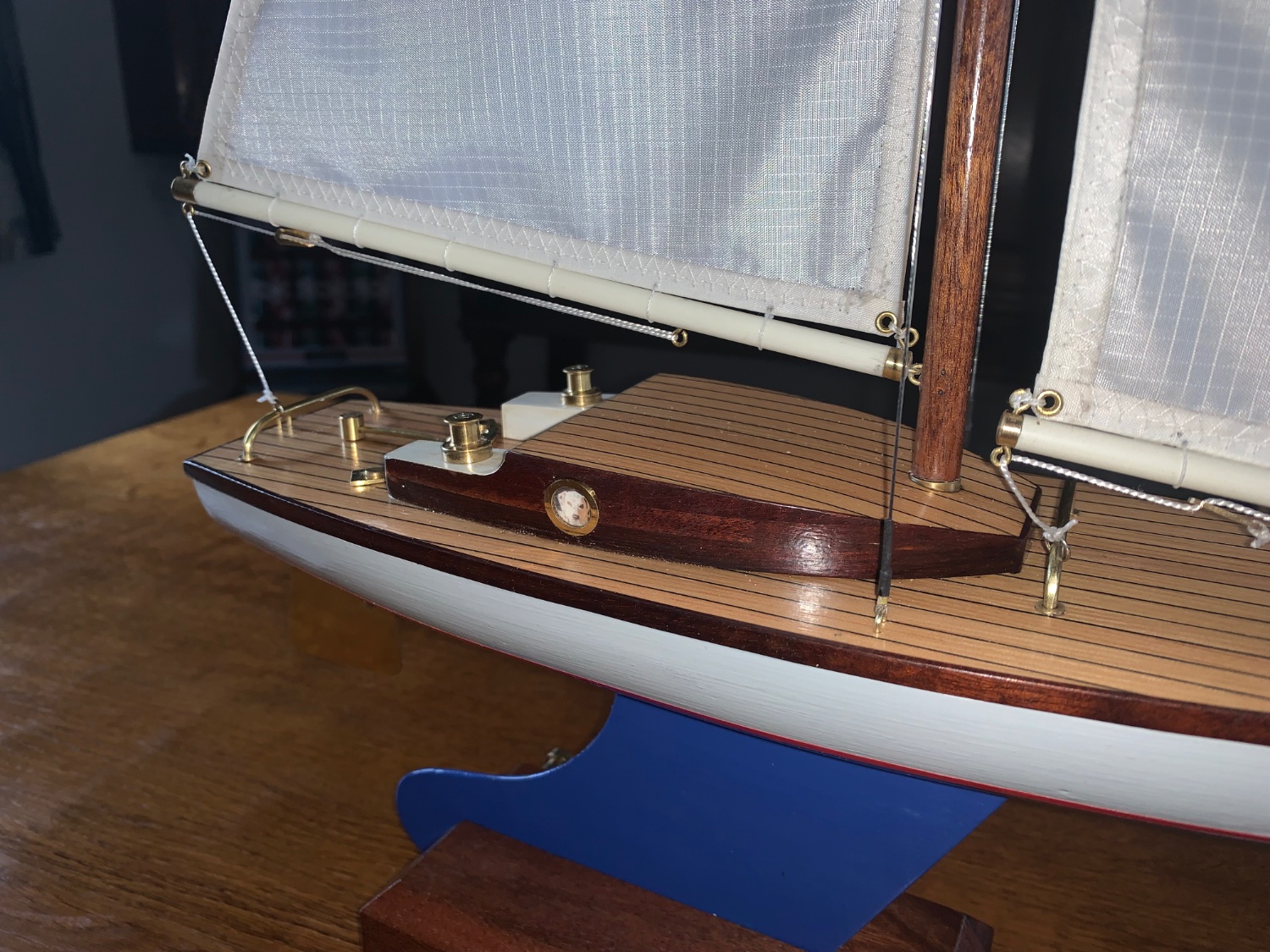
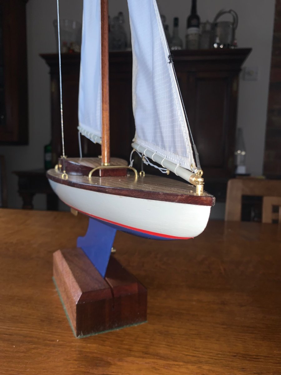
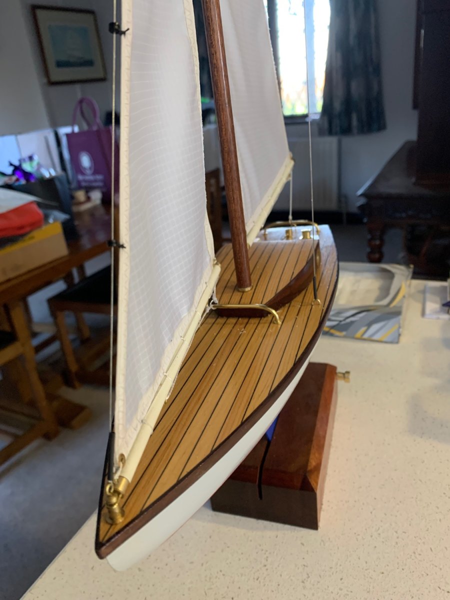
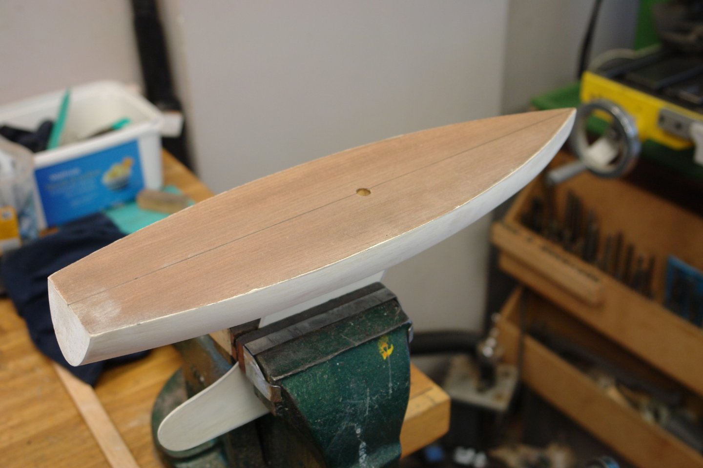
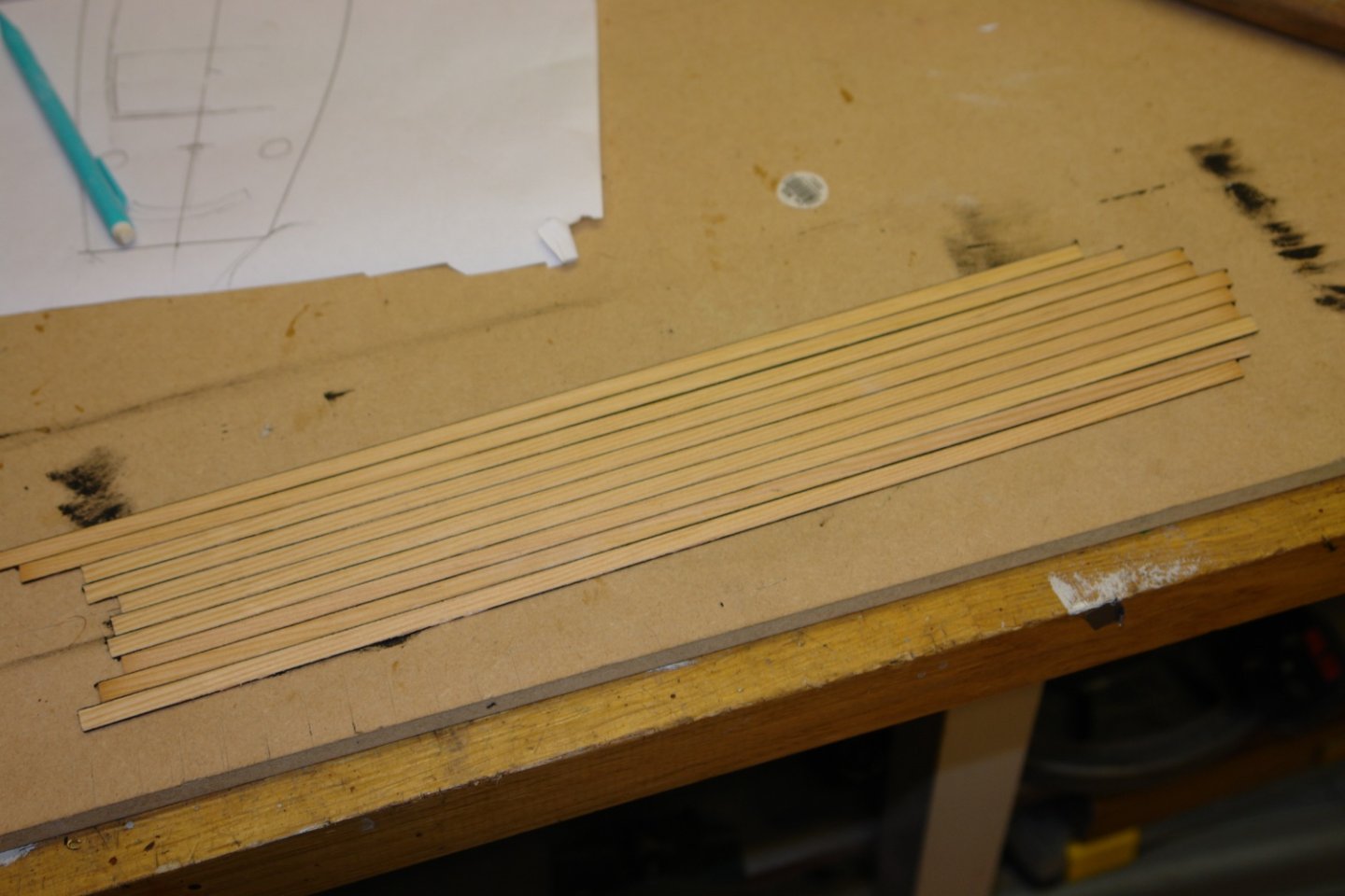
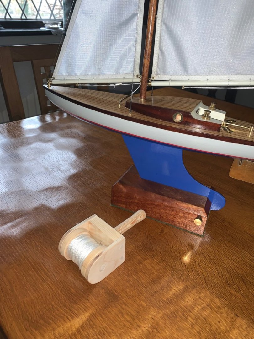
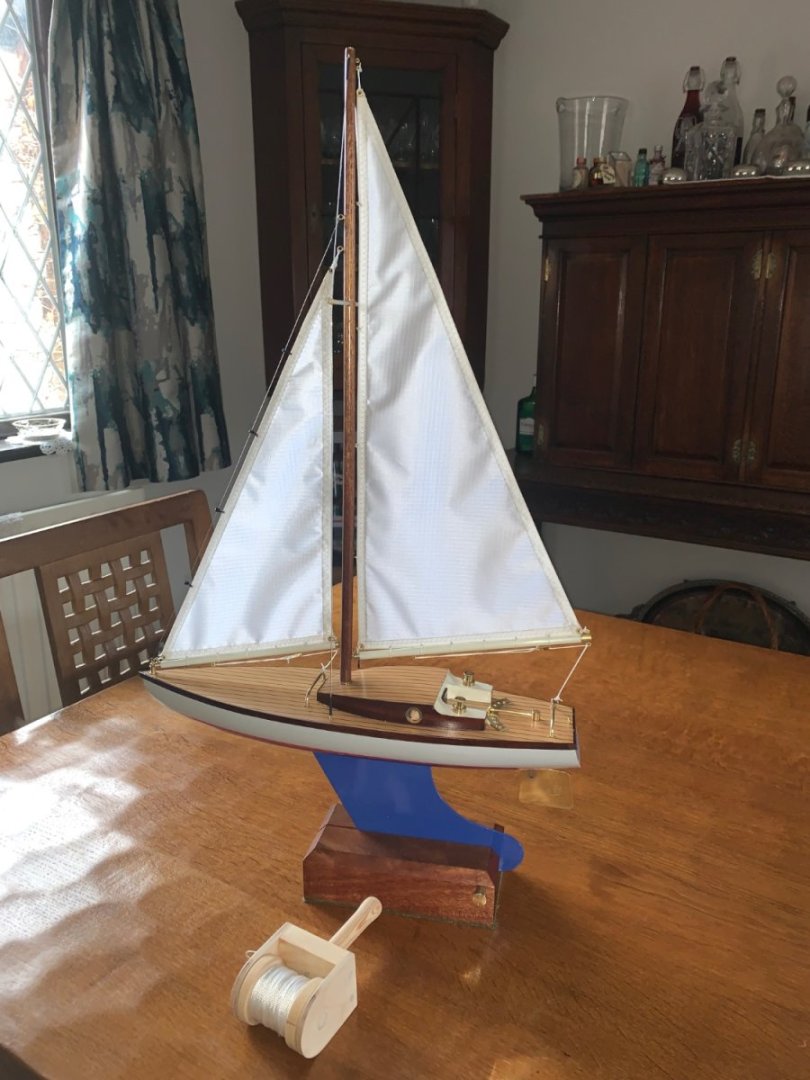
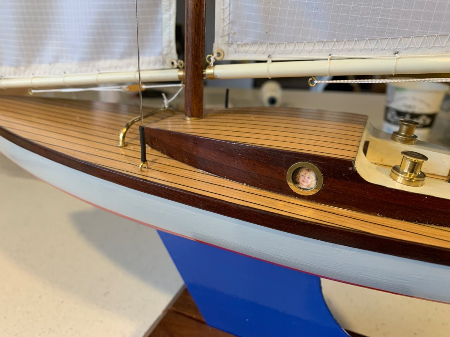
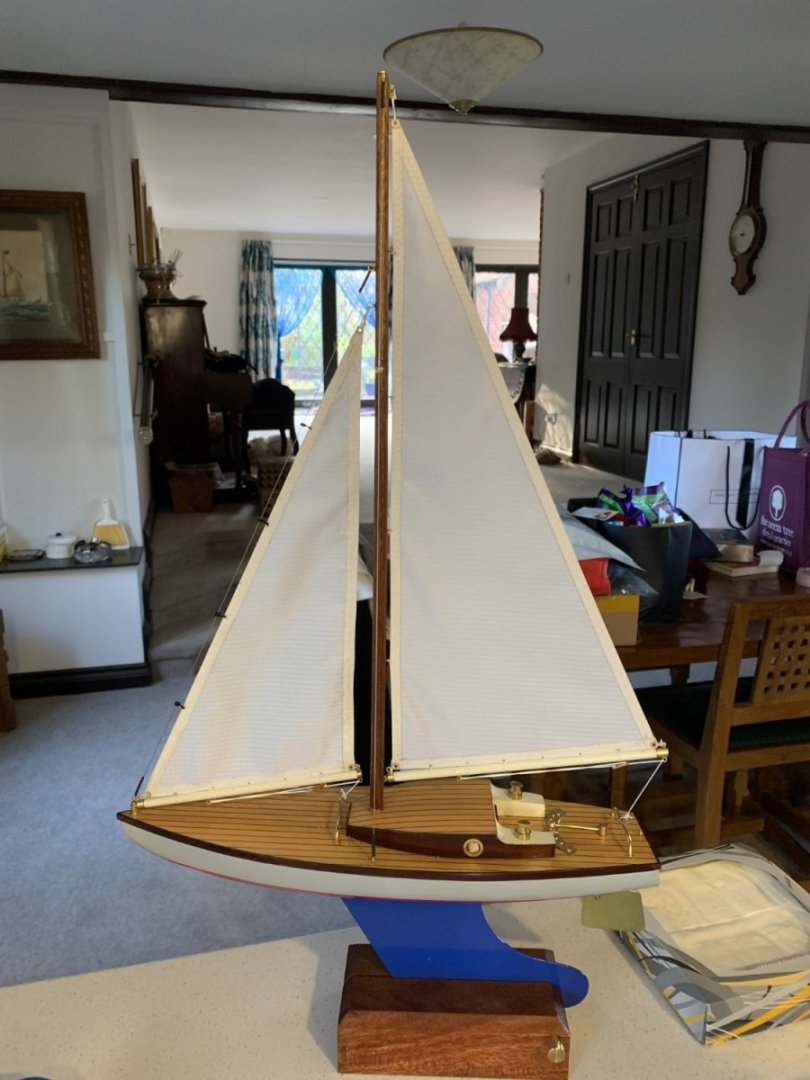
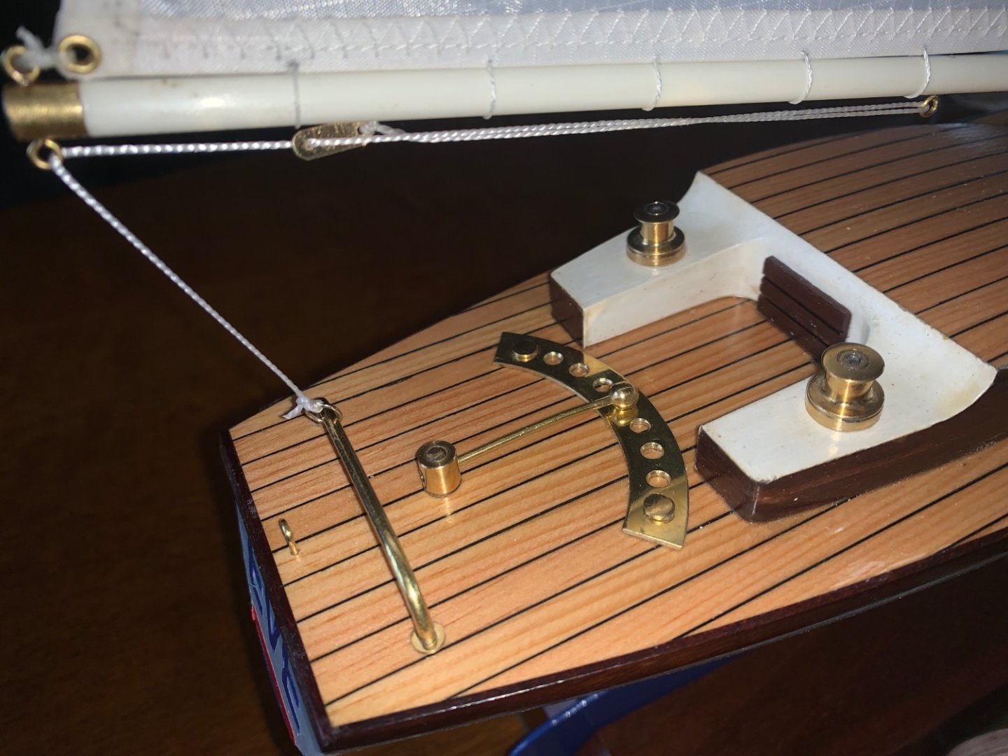
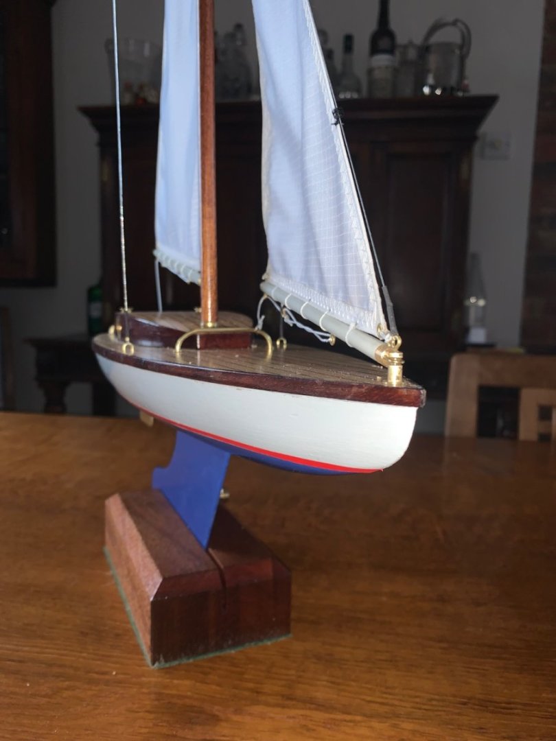
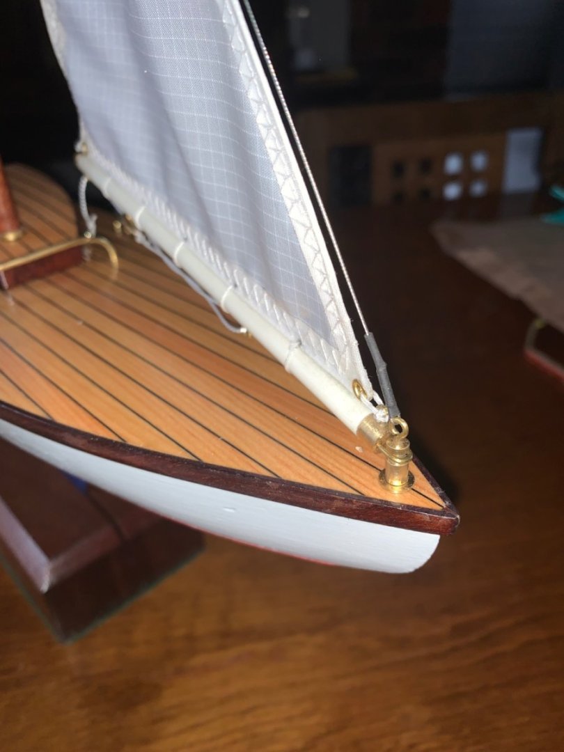
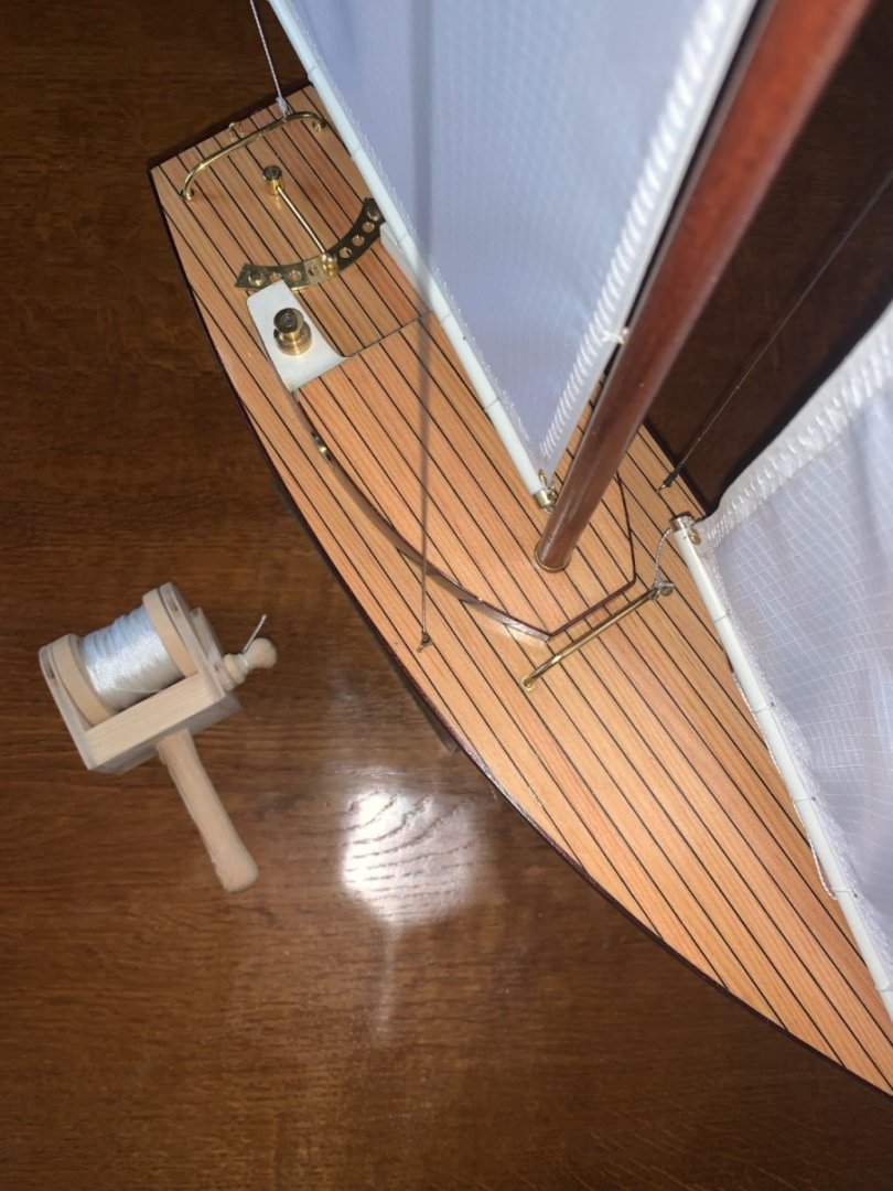
Thank you Pat, Mark and Andy. You may recall that about a month ago I decided to do a parallel build of a pond yacht so here it is. The starting point was an old hull that had been collecting dust in the garage for 35 years plus. My original plan was to mount a mast and hack some sails out of a bit of cloth and give it to the granddaughter (Bean) as a stocking present. But I looked at it and thought the deck might be improved a little. So I got some 1/4 inch thick spruce and glued a sheet of black card to one side. I then slit off deck planks with the pre attached caulking. The planks were then glued to the hull and the edges were planed to match the hull profile. I then started to think maybe i need to elaborate on some of the other features. So the yacht acquired a deckhouse, brass fittings etc. Bean loves Maisie the dog so she had to go on board. And the yacht needed an owner "Captain Bean". Hopefully Captain bean will be a proud owner and therefore the yacht needs a display stand. By this stage I was starting to worry it my disappear over the horizon on its first outing so it got a rescue line. Now it just needs wrapping and sending to Santa.


-
Tom - A charming bunch, you must be very proud. Some of them seem to have outgrown you. I constantly criticise my daughter-in-law for letting my granddaughter grow too fast.
-
Congratulations Brian, a wonderful model and the stand is inspired. It has been a great journey and it has been a pleasure to follow your build. Your craftsmanship and dedication has produced a truly remarkable result that I hope will bring you pleasure for many years to come. 10/10 for your first scratch build, so what next?
-
It is bloody unreasonable, They have 6 and we only have 1. Didn’t their parents ever teach them how to share! And thereby hangs a sad but funny story. Forty years ago both my wife an the next door neighbour “Alison” were pregnant for the first time. Unfortunately Alison’s husband was dead from a brain tumour within the year. After that Alison’s child “Lizzie” and our children were virtually brought up together. At about the age of four Lizzie asked Allison why she didn’t have a daddy and Allison explained why. Lizzie then asked if Keith could be her daddy and Allison explained “No, Keith belongs to Ann” to which Lizzie replied “Doesn’t she know how to share? After about 7 years Alison remarried and we moved to the other end of the country and over time contact became less and less. However 14 years ago we were invited to Lizzie’s wedding and I will always remember at the reception that we were introduced to the groom by Lizzie as “this is Ann and Keith my other Mum and Dad” Lizzie’s mum died about 4 years ago so now Lizzie has adopted us and we her. Both my son (Paul) and Lizzie have their 40 Birthdays in the week before Christmas. Thank you for your support Gary, Phil and Valeriy.
-
Tom, Actually Bakewell In the Peak District - where Bakewell Tarts come from - that’s pastry type tarts. Currently about -5 deg c ( 23 deg f ) - with snow. Every year Chatsworth House ( magnificent stately home) put on a Christmas Fair and Garden light show - Very special - particularly if you have a 3 year old granddaughter called Bean! I love her to bits but it’s her other Grandparents turn for Christmas.😞 Druxey / Keith / Tom - Thank you sincerely.
-
Brian, I wouldn’t have thought about it but I do have to admit that the grain is quite reminiscent of a wake in muddy water. It will be interesting to see how Cairo looks when mounted.
-
My mistake - I meant trichloroethylene - my memory isn’t what it was.
-
Steve - she has been there for several years, she is not for sale but does have a waggely tail.
-
Some dodgy solutions of the past had the merit of actually working - unlike their modern equivalents. 40 years ago you could buy a paint stripper called Nitromors. It had a water like consistency and one bottle would cover acres of surface. Within seconds of application the paint would start to bubble and it would happily lift multiple layers within 30 minutes of application (while eating its way through any floor covering beneath the work area). Many years ago it was replaced with a jell which gives limited coverage and cleans the paint surface effectively while producing limited blistering of the surface layer, if you have a few days to spare and unlimited funds it will eventually deliver an inadequate result. Likewise Colron used to make excellent wood dyes. They covered in one coat, penetrated deeply into the wood and produced excellent results. They then replaced them with water based alternatives which were so hopeless I stopped buying them. I am sure that many products have become environmentally more sustainable and safer at the expense of function.
-
It was our standard degreaser when I joined Rolls Royce in 1969. We had open vats of the stuff and most of the apprentices got their chance to bath in it as they stripped down and cleaned engines. We were tough in those days.
-
She is an elegant vessel Jon. I look forward to seeing how she develops.
-
Hakan, Neat idea. I tend to plank with the hull inverted and I have seen others planking half hulls before joining along the centre line, however I can see that your solution has merit.
-
Andy, It sort of depends on the family and Christmas plans. My sons 40th Birthday on 21 December and we have booked a few days away to celebrate, we have even invited him, his wife and our Granddaughter. He has also chosen to move house next week and requires the usual help with all those jobs 40 year olds haven't been trained to do but 70 year olds find to be second nature. I probably have about 30 hours ship work left so it may be possible to get it finished (excluding support cradle) by the time Santa drops down the chimney.
-
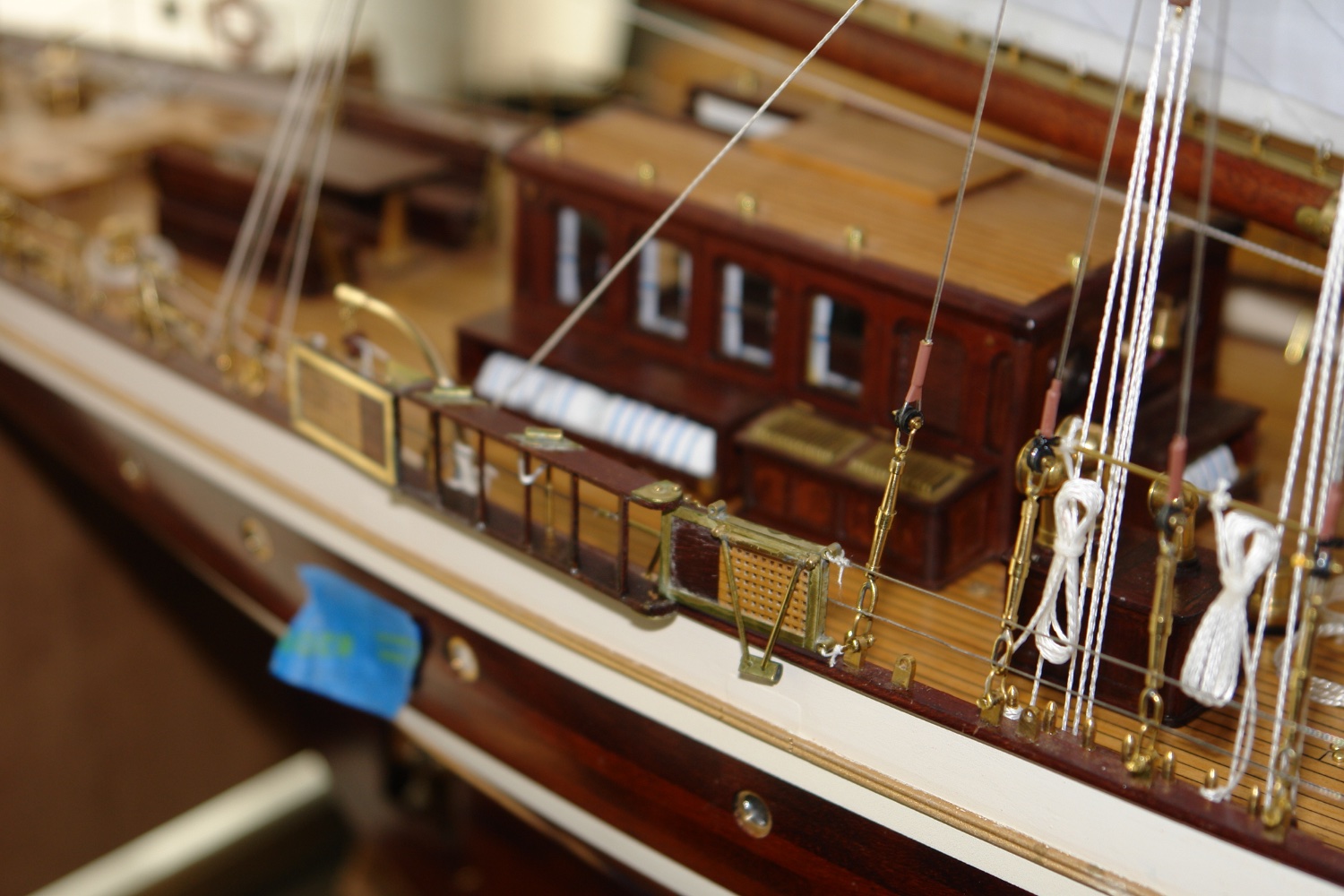
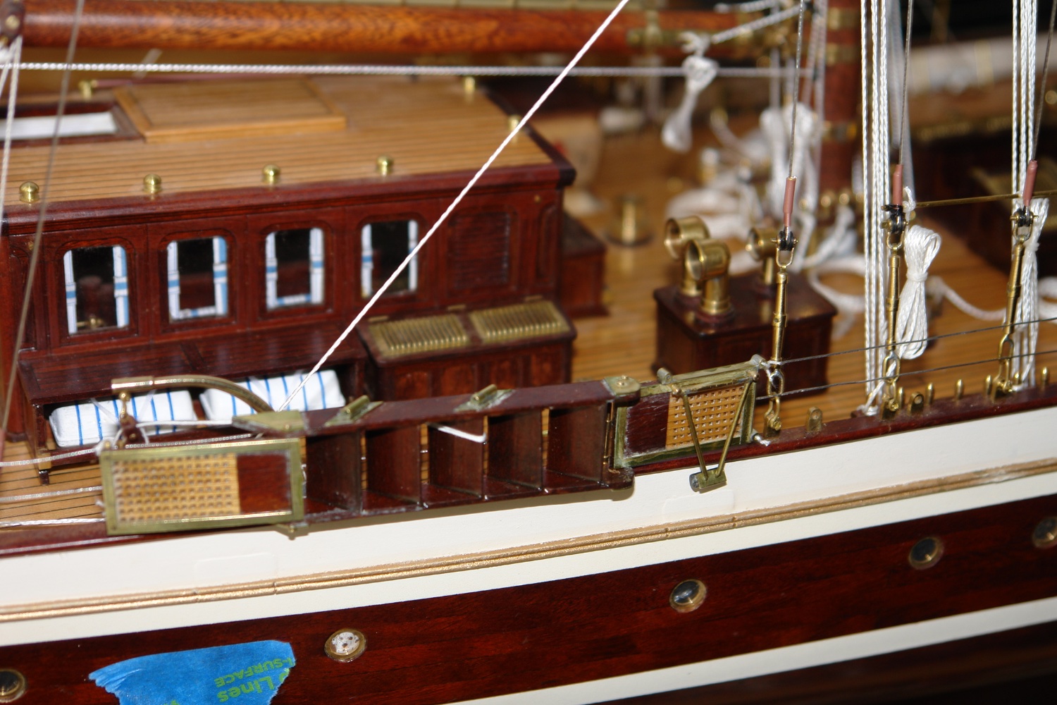
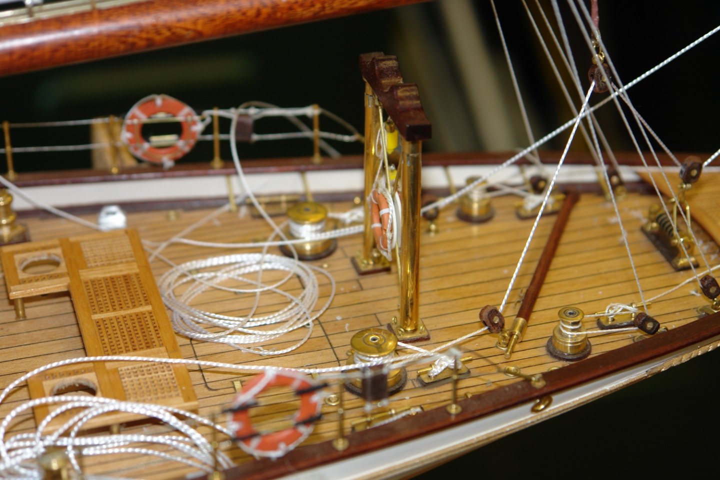
Thank you Andy and all my other build visitors. Back to tidying up all those lines starting with the main sheets:- Then back to tidying the halyards and hanging the hanks from the rail attached to the shrouds. The derrick for the steps then needed to be finished with blocks and attached to the rail. Followed by the lashing of the steps to the rail. Not much more to do now!


-
I think the gherkin clamps are particularly inspired. 😀
- 132 replies
-
- 4
-

-
- charles martel
- battleship
- (and 1 more)
-
Hakan - Fantastic news - but as i said previously, Doctors aren't nearly as accurate as the average ship modeller. Good that they were wrong on this occasion. I assume the surgery is to reinstate the normal bowel function. Tell the surgeon that leaks are not tolerated by shipwrights. Good luck mate.
-
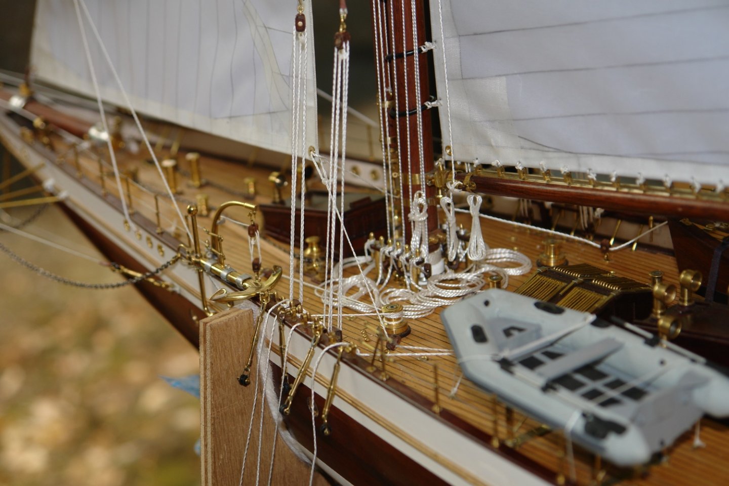
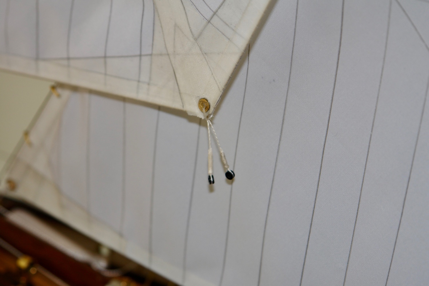
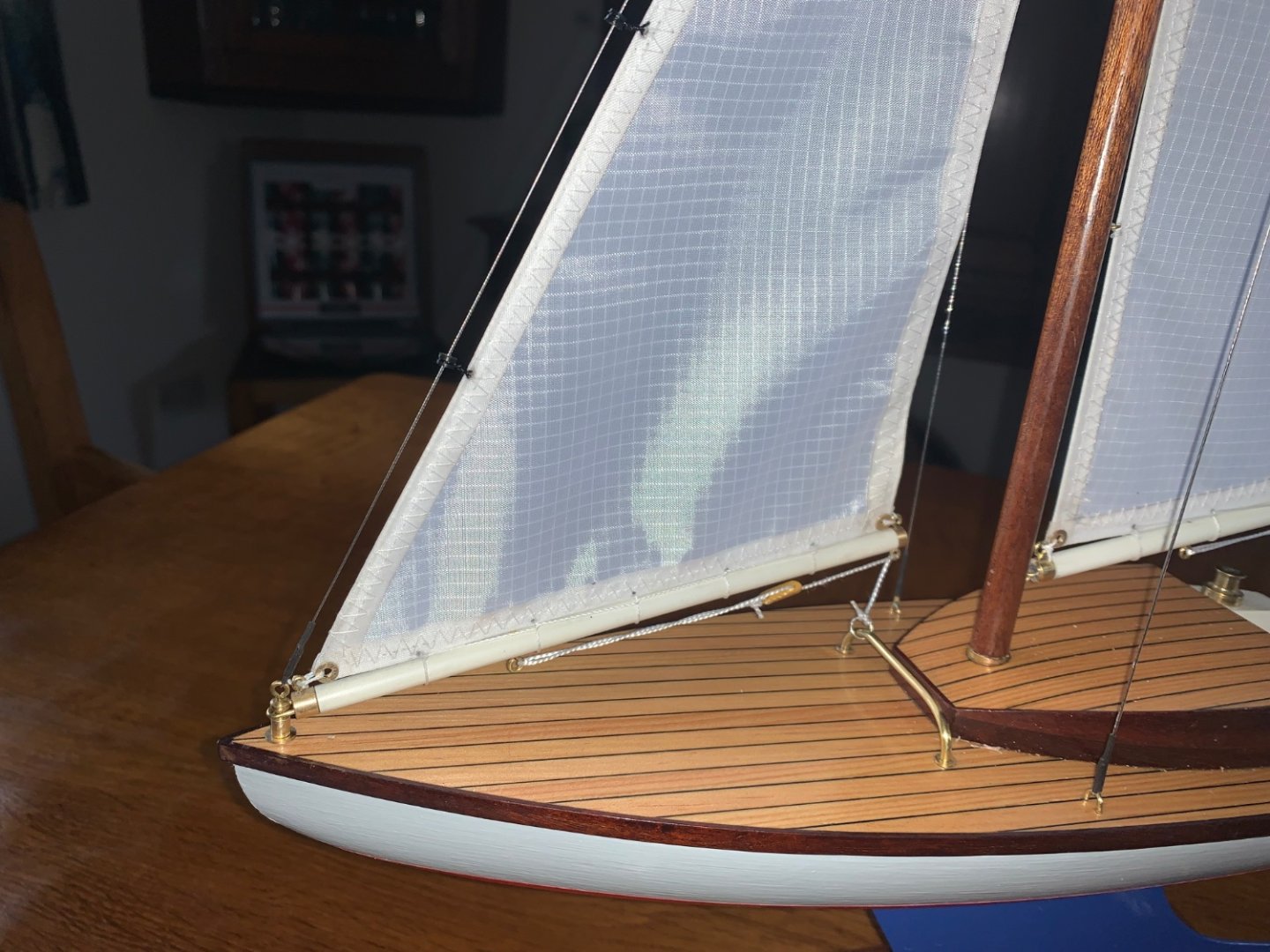
Veszett, yes that is what I assumed. This is how the jib is rigged but the staysail and the flying jib both have single sheets on either beam. Thanks Brian i'll give it a try. Thank you Eberhard, Ken and Phil for your supportive comments. also thanks to everyone for the likes.
-
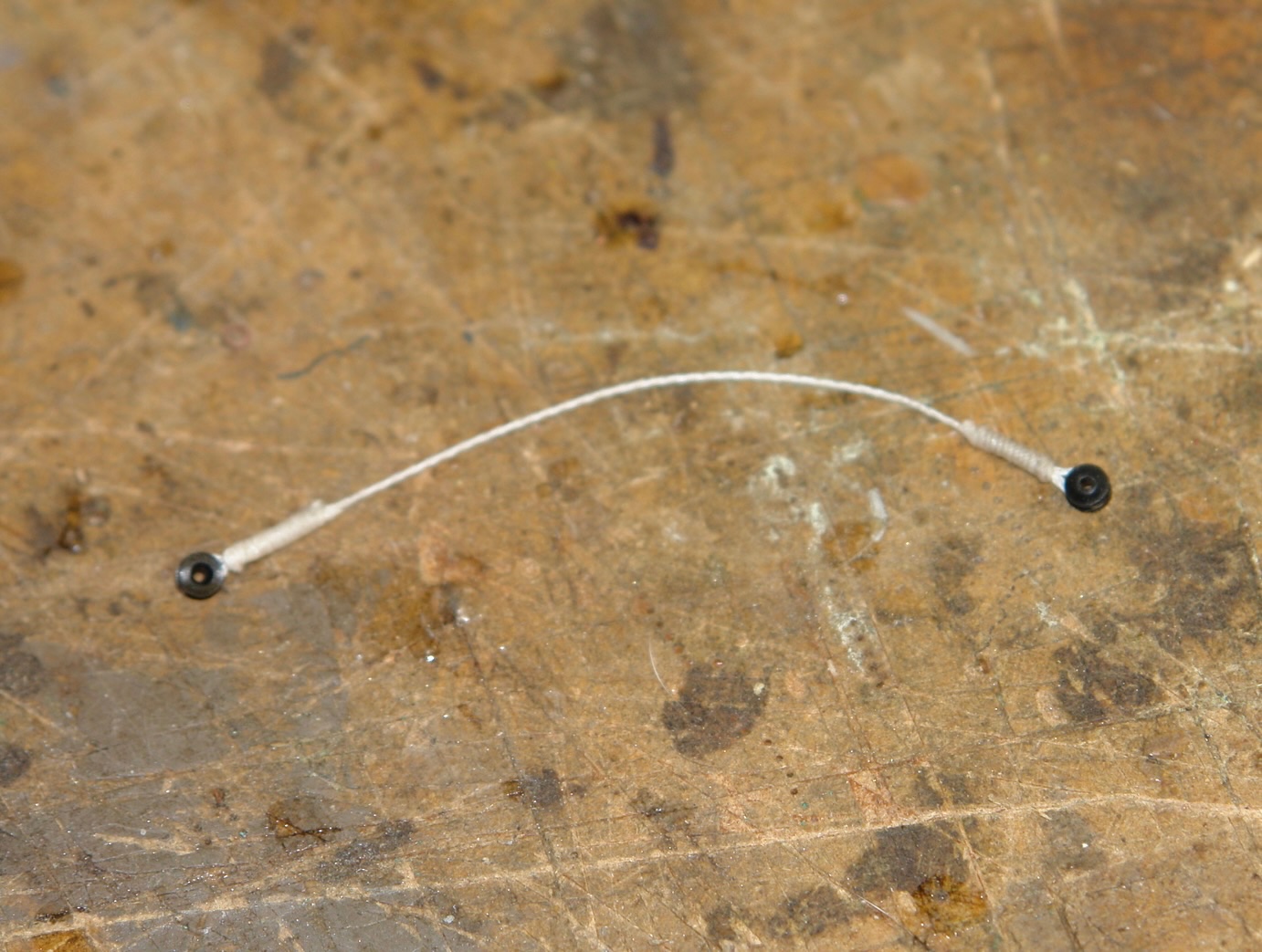
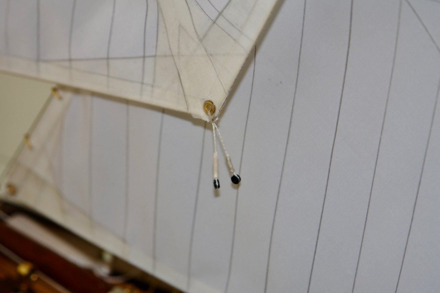
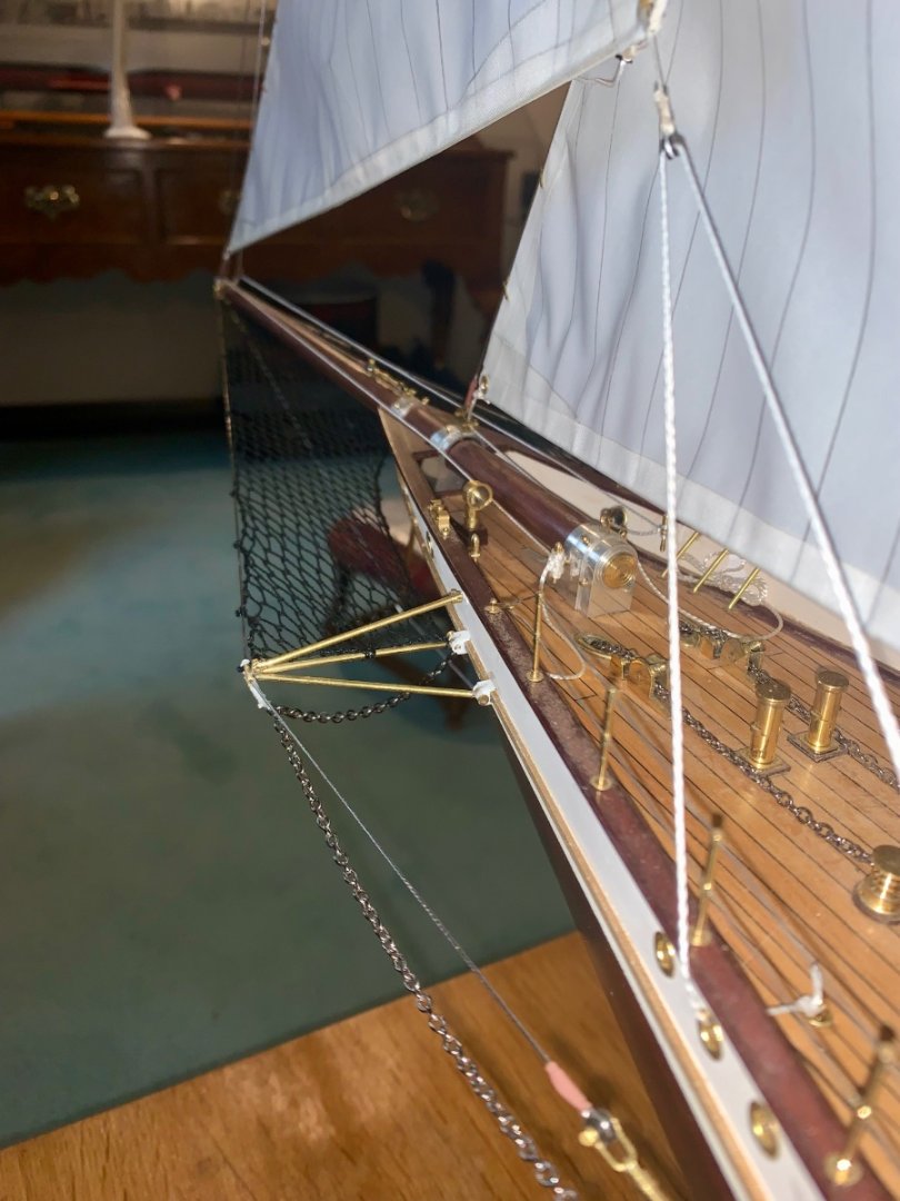
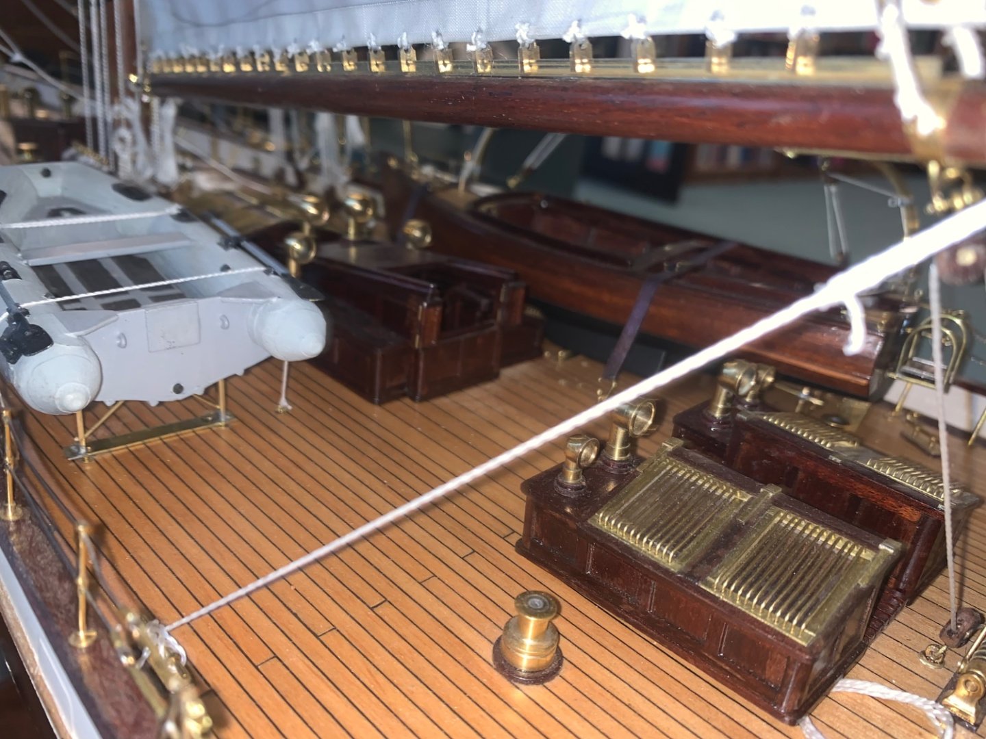
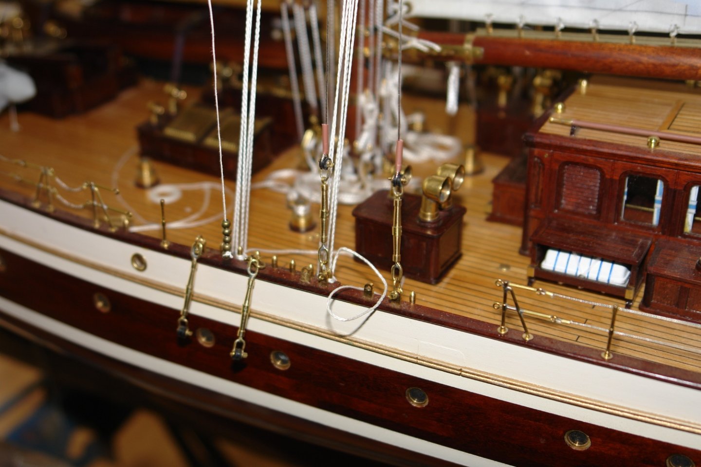
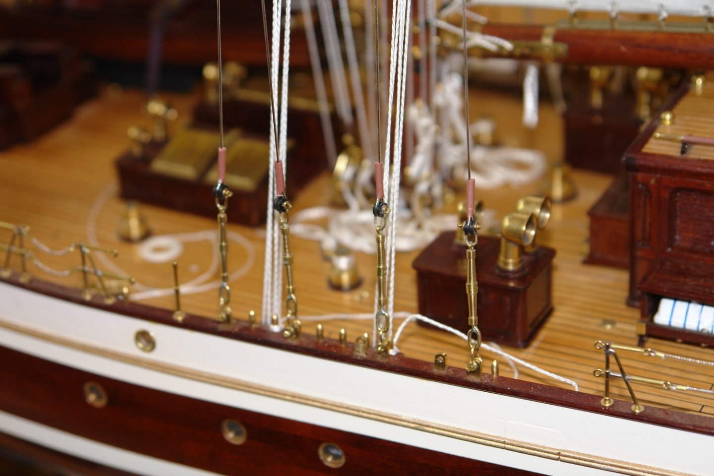
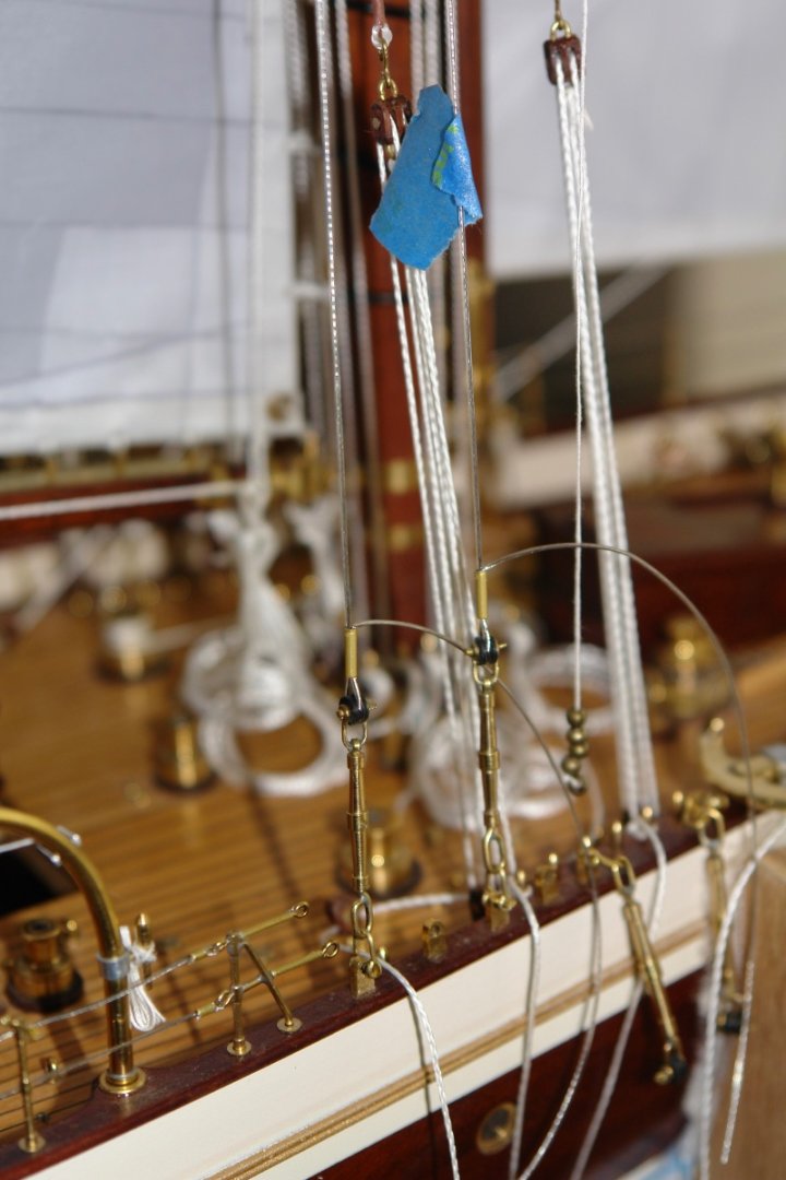
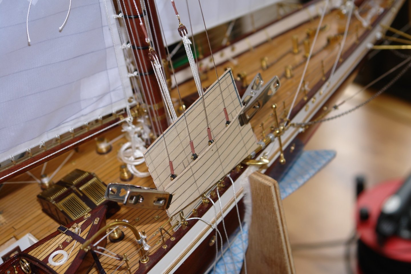
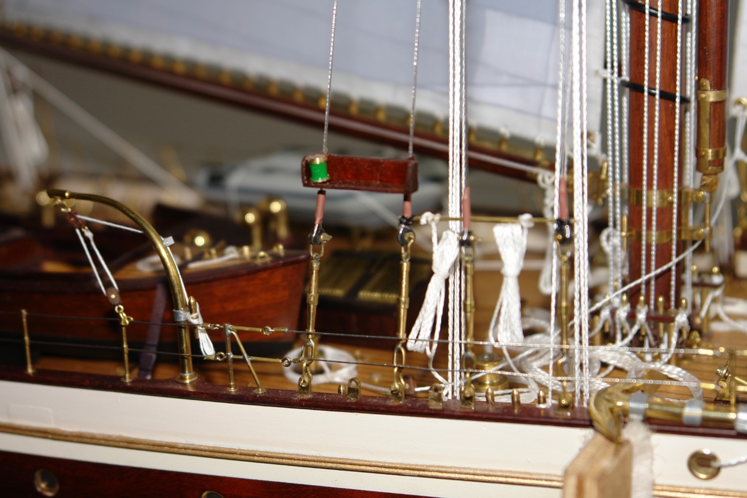
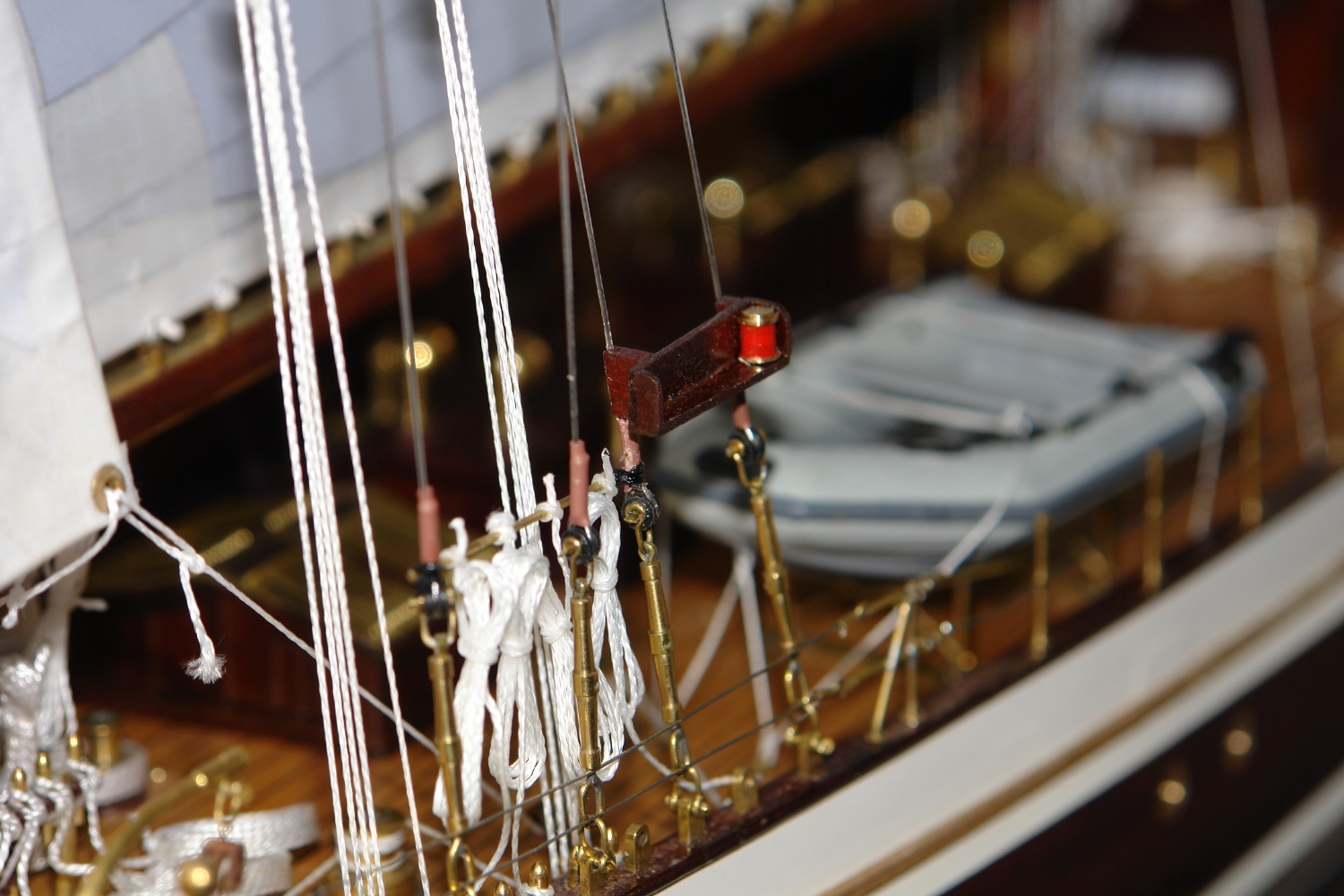
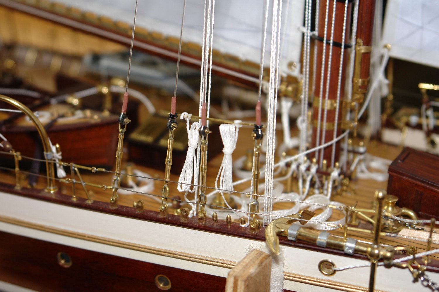
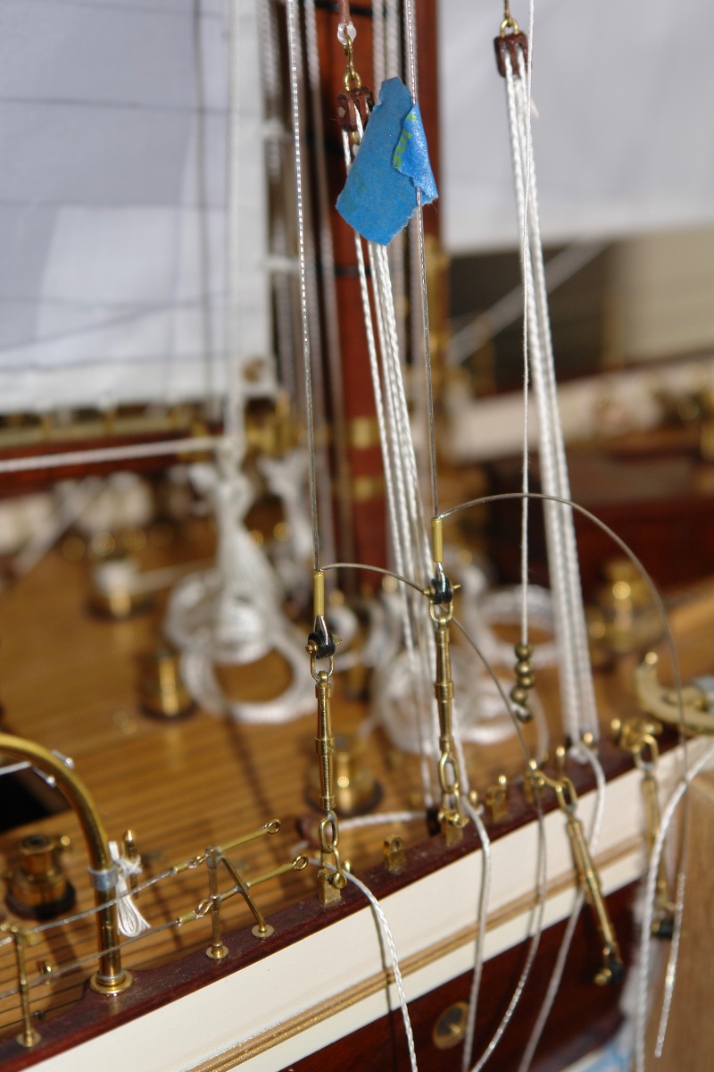
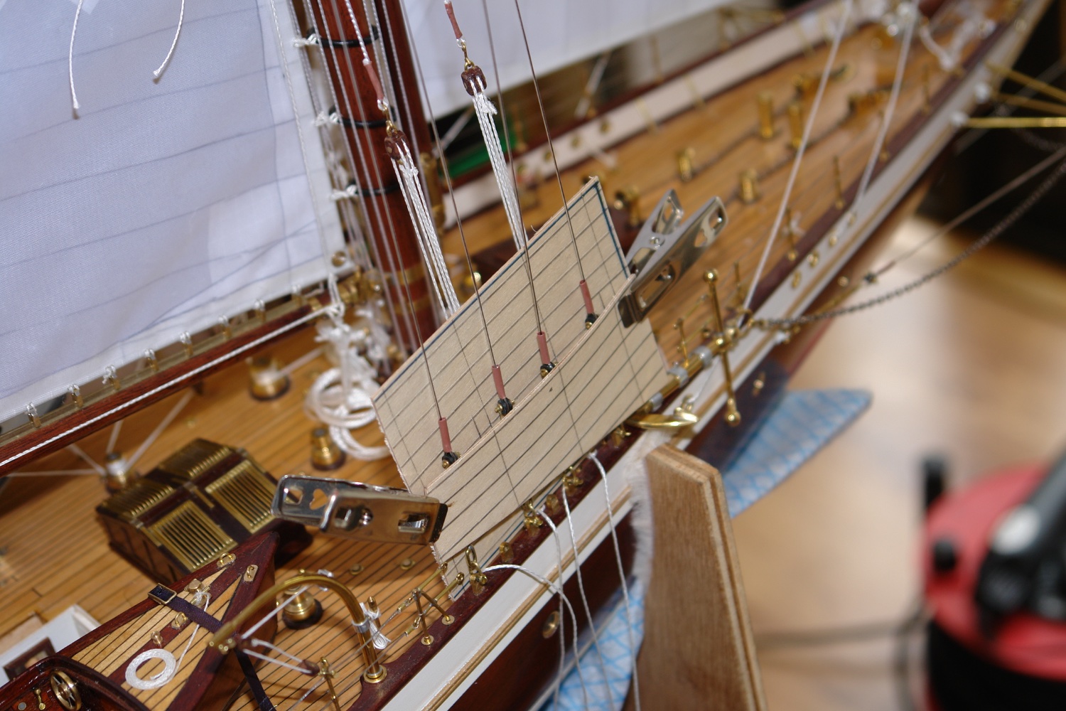
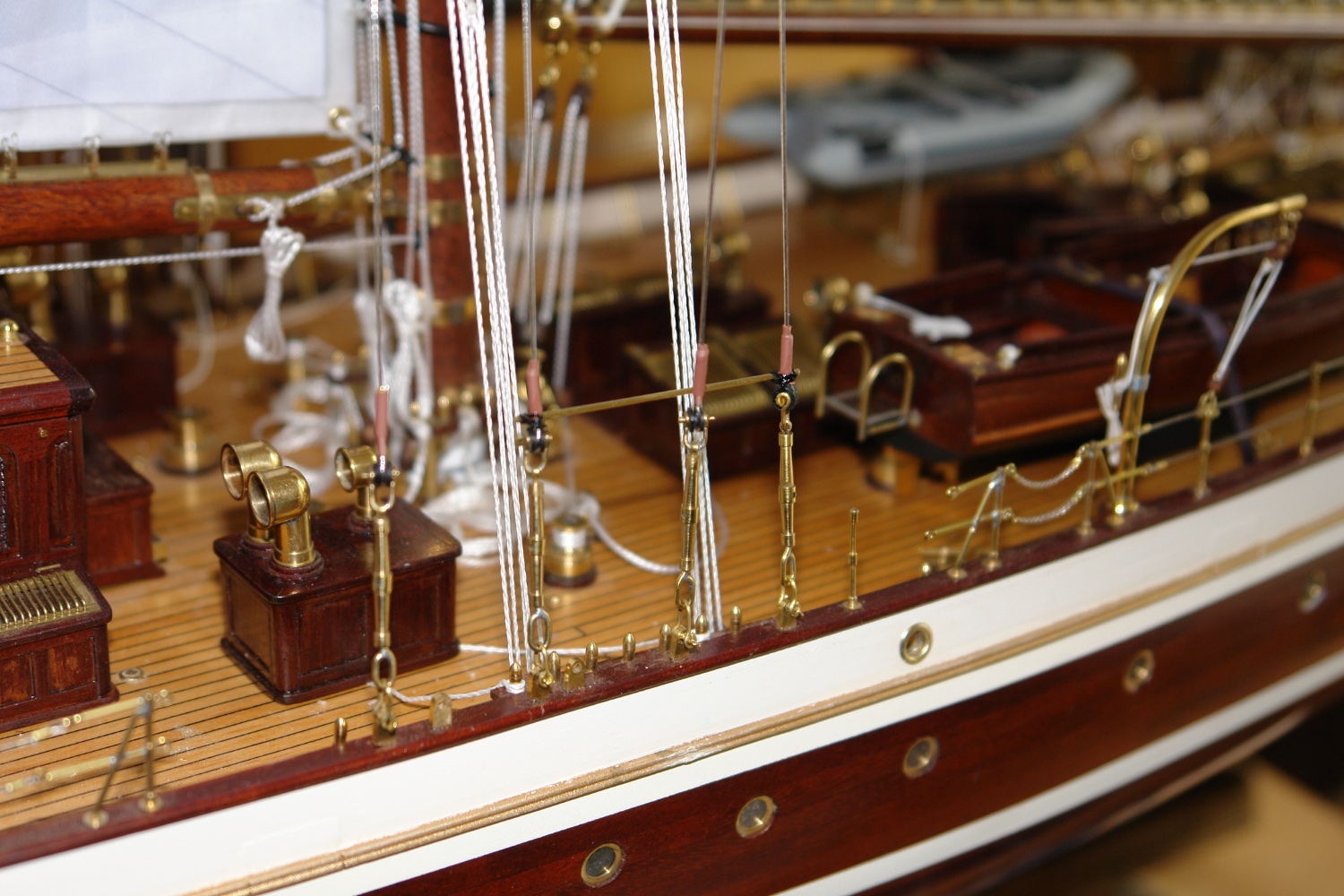
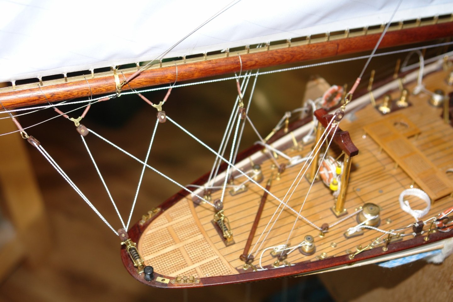
I am in that final stage of building where it is a case of bouncing randomly from one area to another finishing off bits of detail. I apologise that this post may be a bit disjointed. The jib has an unusual arrangement of twin jib sheets on each side. These sheets slide in thimbles. The sheets are variously rigged on the photos i have but in general they are run outboard of the bulwark before retuning to the deck via various apertures. I am rigging the boat on a starboard tack and so I have rigged preventers to hold the fore and main booms to port. I then moved on to rigging the main mast shrouds. The two lower shrouds have been attached to the turnbuckles in the next photo. The upper two were then rigged completing all 4. I worked on both sides simultaneously to keep the tension equal and the mast vertical. I then repeated the process for the main mast The plywood in the next shot is protecting the lines from the heat applied to strink the heat shrink tubes on to the shrouds. The heat gun is quite capable of melting the line and undoing previous work. The rail above the turnbuckles is lashed in place and will support the various halyard lines.