KeithAug
-
Posts
3,980 -
Joined
-
Last visited
Content Type
Profiles
Forums
Gallery
Events
Everything posted by KeithAug
-
 Hakan - I was wondering how you were doing. The road may be rough but despite the ups and downs the general trend will be one of improvement, it just takes longer than we expect. Hopefully the worst has past.
 -
Ah, I found the answer in the post by FrancisMcN earlier in your build. In his model the deck extensions seem to be hinged to fold up. Why did you decide to omit them on your build?
-
Ras, I was wondering how the gun could fire on the beam as the firing position would necessitate the gunner hanging over the side of the boat. So I looked back at plan which seemed to indicate that deck extensions were fitted on either beam. Was this the case and if so were they demounted and stored when the gun wasn’t in operation ? If so where were they stored.
-
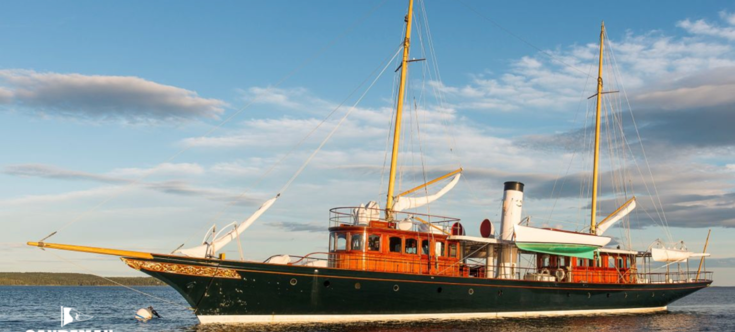
Eberhard - I sort of had a similar thought. I was wondering about getting a name plaque made that includes the web address of this build log and maybe even a QR code. This begs the question about the longevity of MSW or maybe even the internet. I wonder what the shelf life will be of internet information - possibly longer than a tablet. Andy - sadly not, I think I would be alarmed!!!!! Thank you Brian. Brian / Mark - I think I am well on the way to amassing enough information to attempt Cangarda. 1:48 or 1:36 scale would be sensible but I am wondering about the non sensible scale of 1:24. Andy Druxey, Keith, Brian, Rick, Mark, Michael, Richard, Pat, Roger, Eberhard - Thank you all for your comments and also thanks to all of you that have contributed to and like the build over past 4 years. Just think it, 4 years older and according to my wife not an hour better!
-
Good to say the workshop temperature jumped up the 12c (from its winter 6c). I had to take my jumper off! I hope you are getting out to your workshop Hakan? Best wishes - Keith.
-
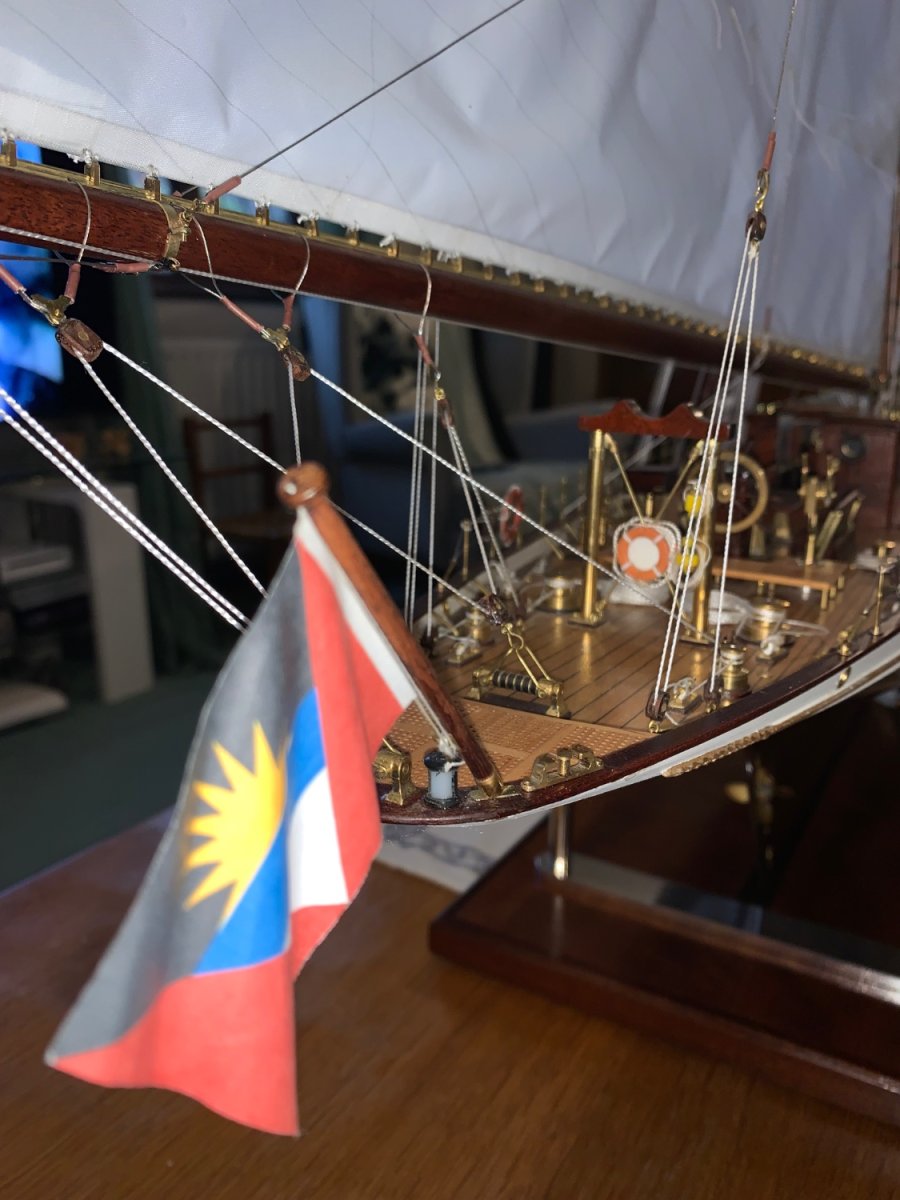
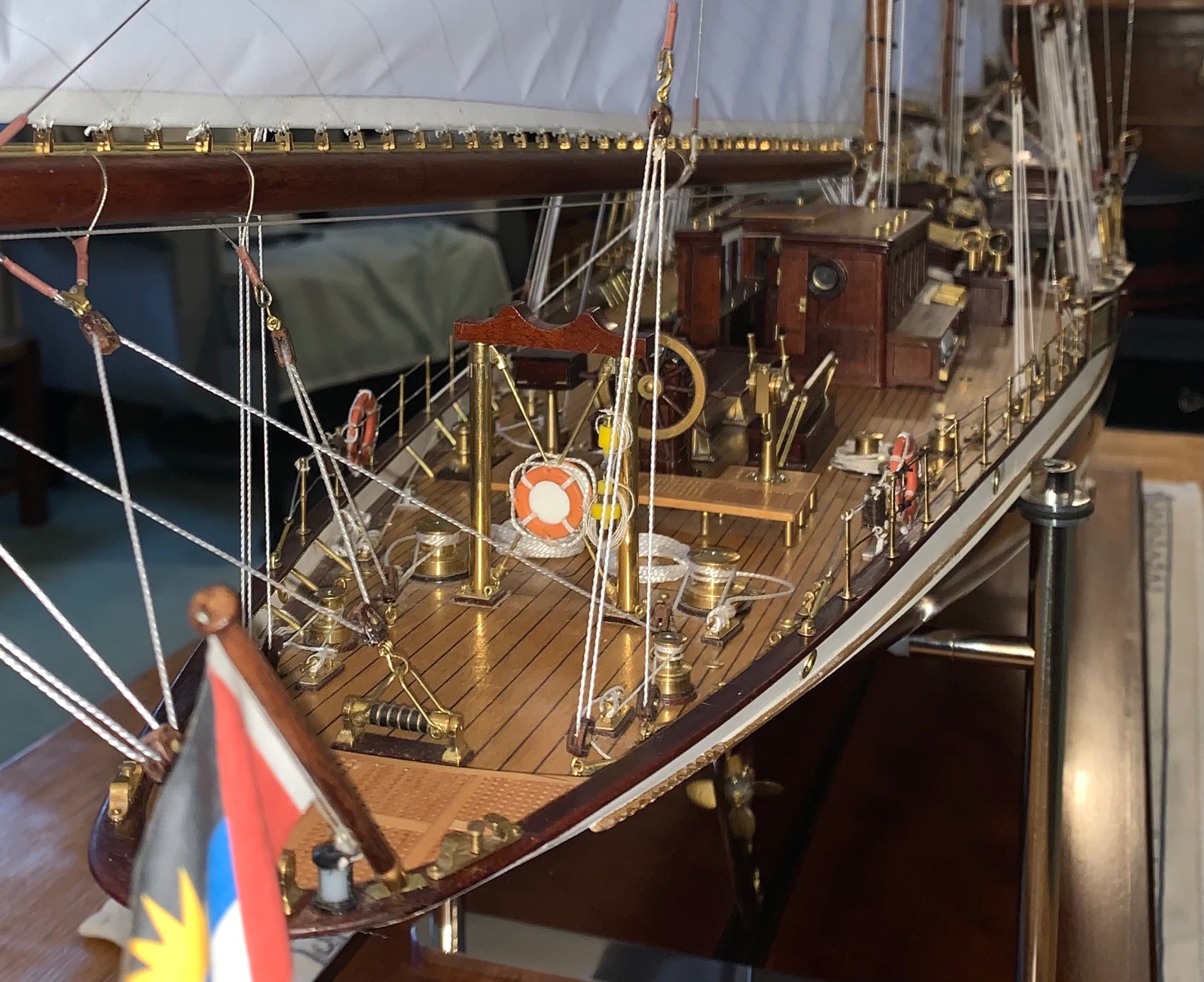
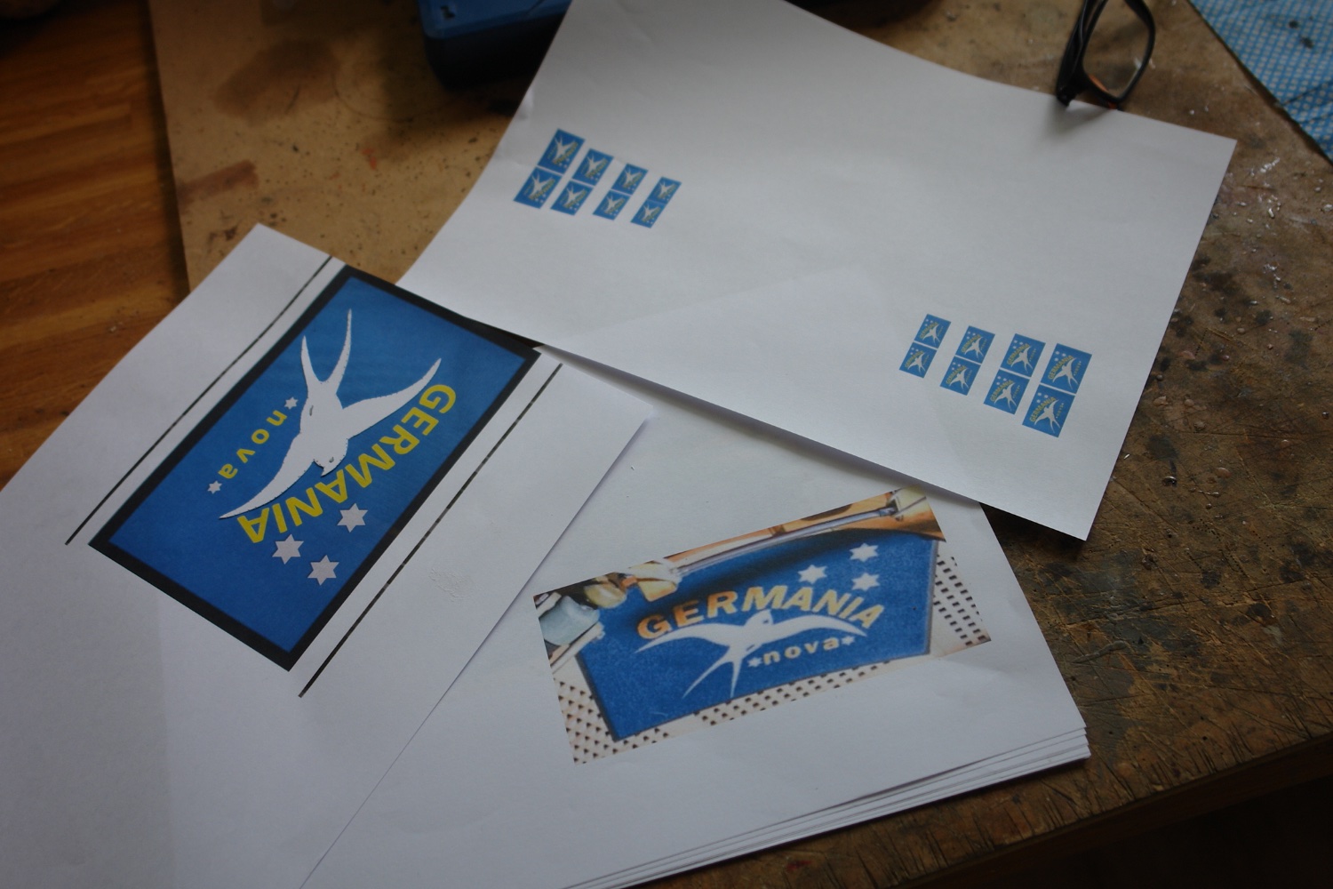
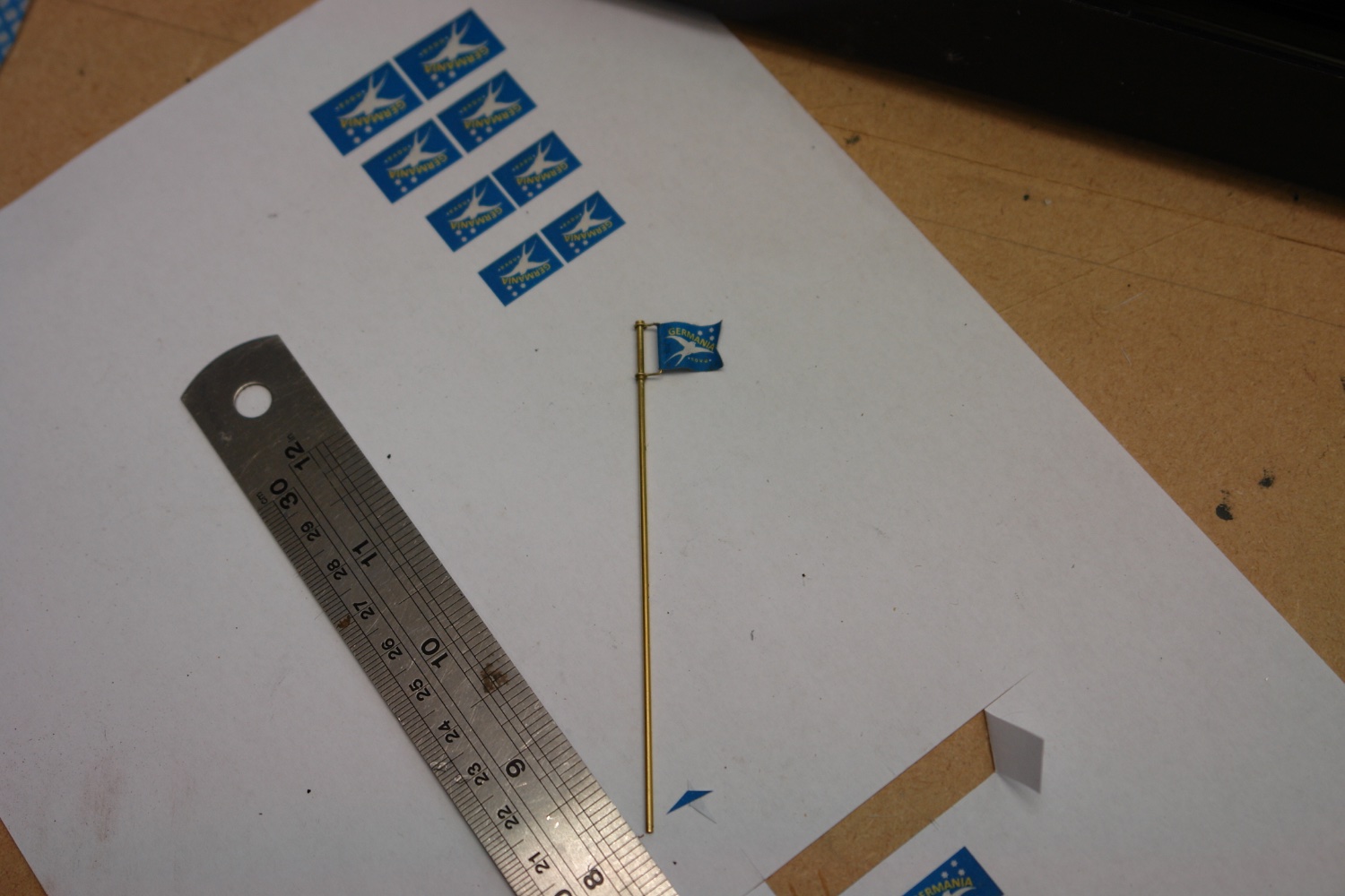
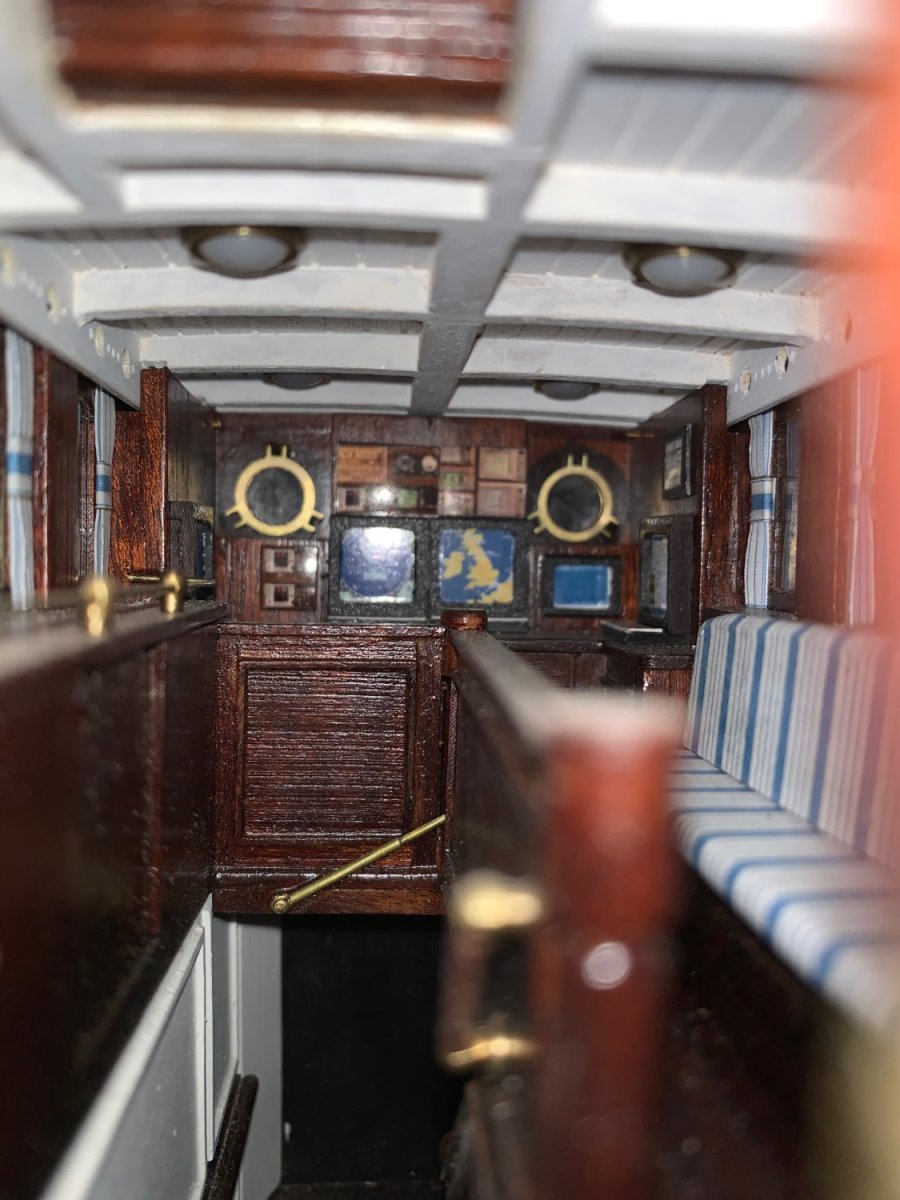
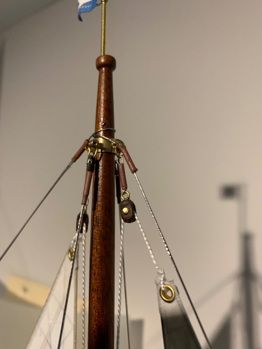
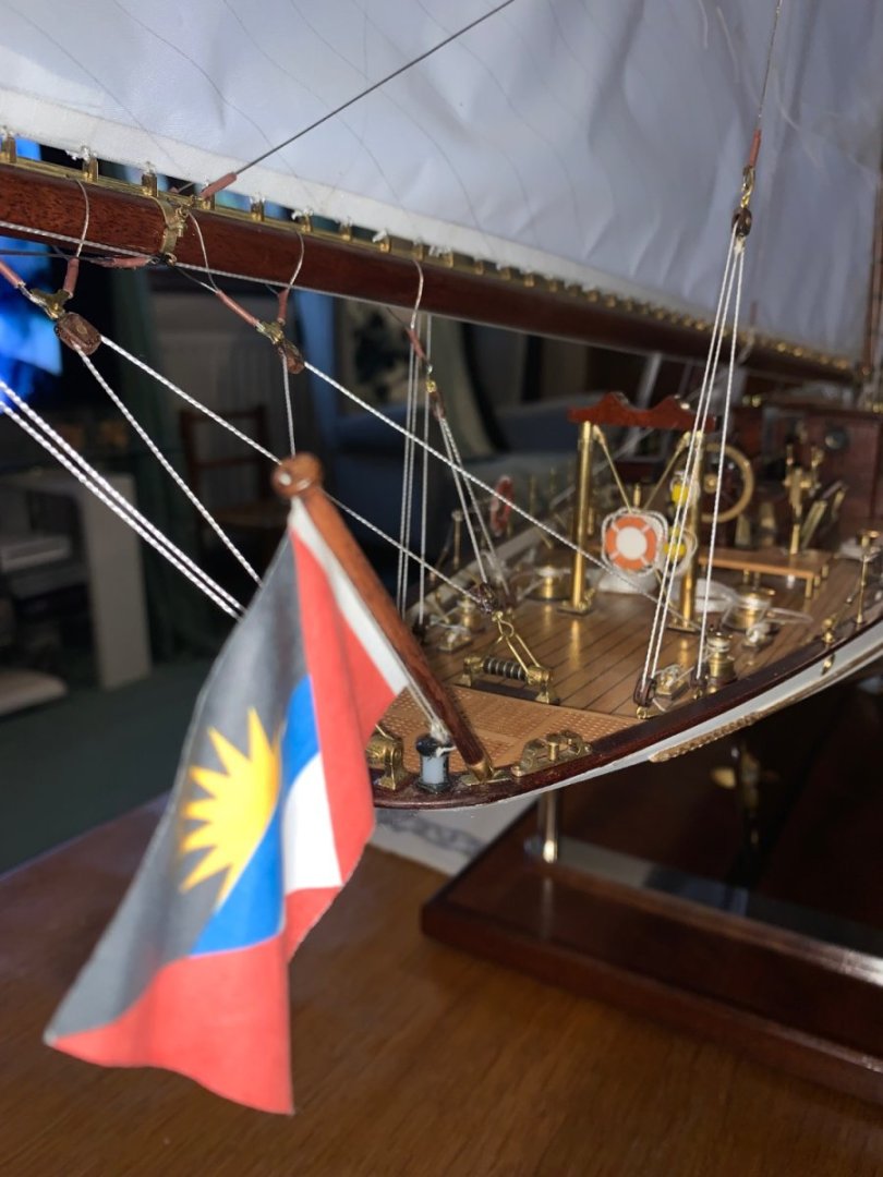
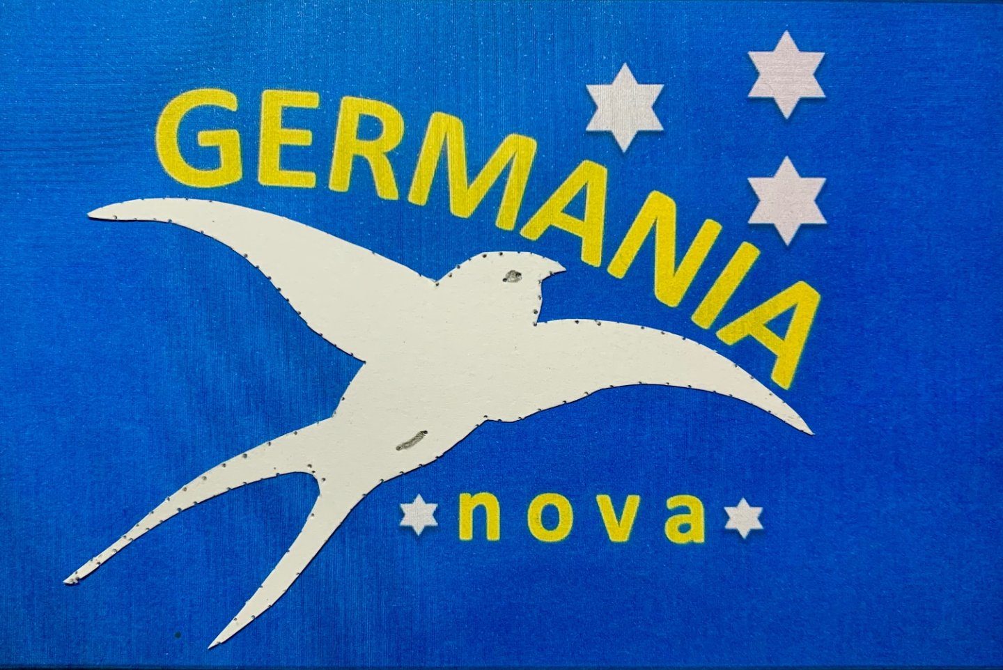
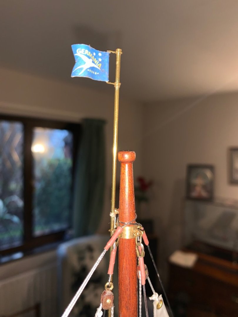
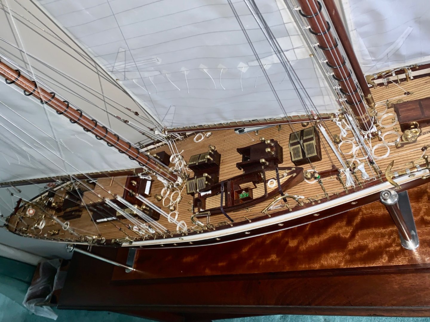
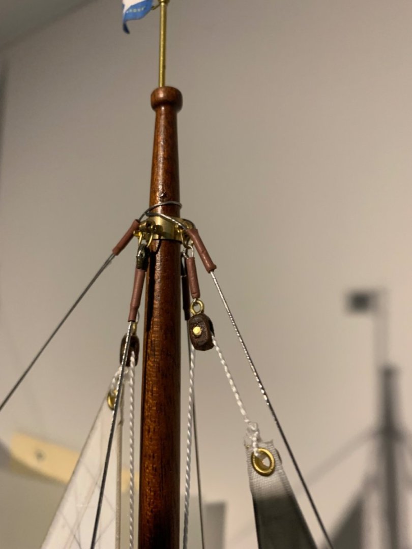
Once again thank you all for your continued interest. I finally finished the outstanding bits but as yet haven't taken a comprehensive set of completion photos. Here are the final bits of the build and a few photos. The burgee carries the owners flag. This contains of the boats name stars and a swallow. I made this up at A4 scale using powerpoint. The swallow was drawn freehand, pricked out on a piece of card out out and glued on. As the burgee was being reduced down to about 1/4 x 3/8 inch I wasn't too worried about the pin holes. The pig stick was made out of brass wire. It was then hoisted on the fore top sail. The ensign was then made from paper. This was printed in two operations with the paper flipped over and aligned to get the two images perfectly symmetrical. I may make it again with thinner paper but for the moment it will suffice. The paper was bent round a pencil to get it to hang as if their was a very gently breeze. as you can see from the ensign the boat is registered in a "port of convenience". I then tried a few shots of the deck but was dissatisfied with the general builders dust over the deck surfaces. This curtaiedl my photography efforts but i did take one shot peeking through the open door of the deckhouse. I will clean the model and then take more shots before posing them over the next few weeks.


-
As always very impressive work Eberhard. The oars are particularly realistic but I’m not sure how you manage to keep them so straight and smooth given the assembly method?
-
Brian, sorry to hear about your marital problems. You give them the best years of your life and they just toss you out with the trash. Chin up mate, maybe someone better will turn up.😀
-
My workshop has been sat at about 6c for a month or so. The other day I went in and it seemed somewhat warmer so I looked at the thermometer - 9c! Today it's back to 6c. I can only stand it for about an hour and half so not much is getting done. Work gloves and two jumpers help. I recall a 1940s war film where an occupant of a POW camp burns his model boat to keep his hut warm, I sometimes consider it Good to see you made it back to the workshop Hakan.
-
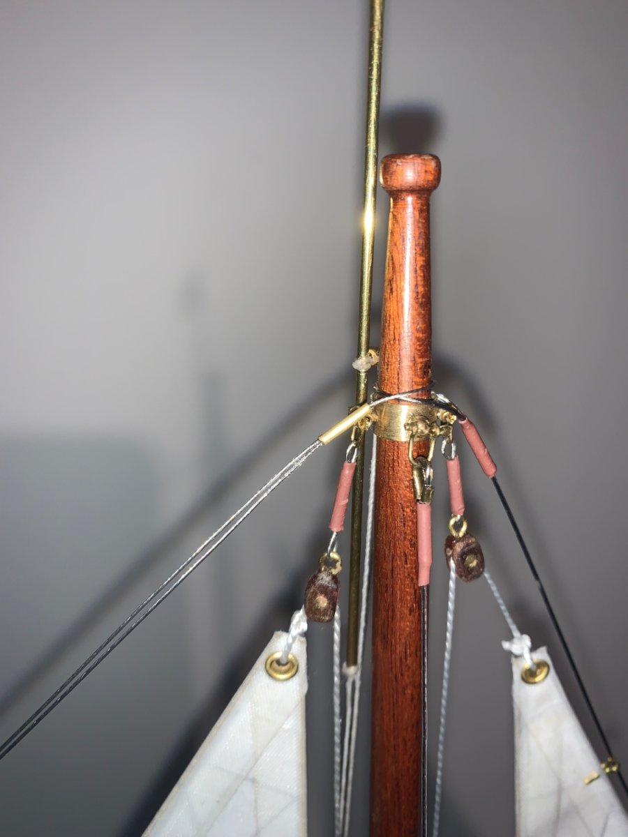
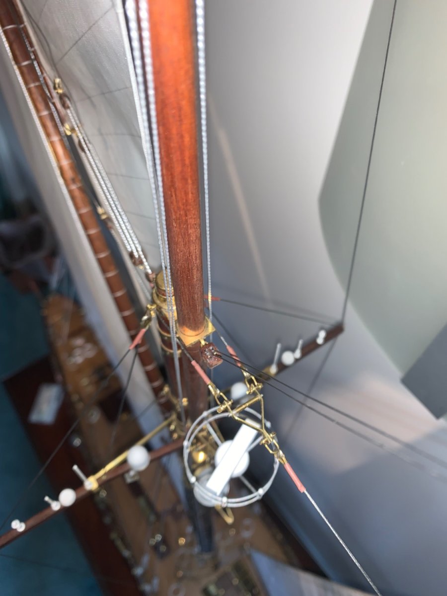
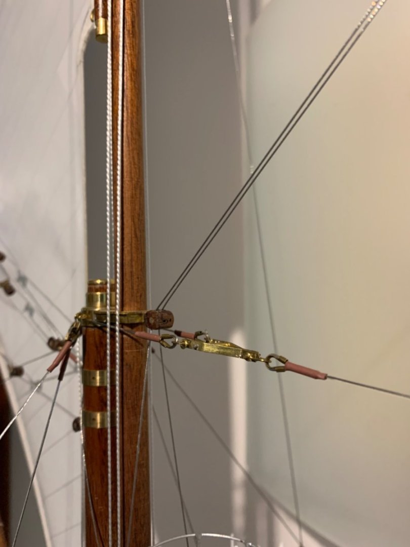
Phil, I probably didn't explain it well enough. When rigged the fishermans sail is hoisted between the two stays and the downwind stay is loosened to allow the sail to take the correct shape. With the fisherman set only one back stay is bracing the fore top mast at any one time. Because I have not installed the fisherman I have tightened both back stays. When tightened the load path is from the top of the fore top mast to the top of the main mast. The majority of the load is then transmitted to the deck via the main mast back stays. The blocks tightening the twin fore top mast back stays are split on to port and starboard beams. Thank you Druxey and Brian for commenting.
-
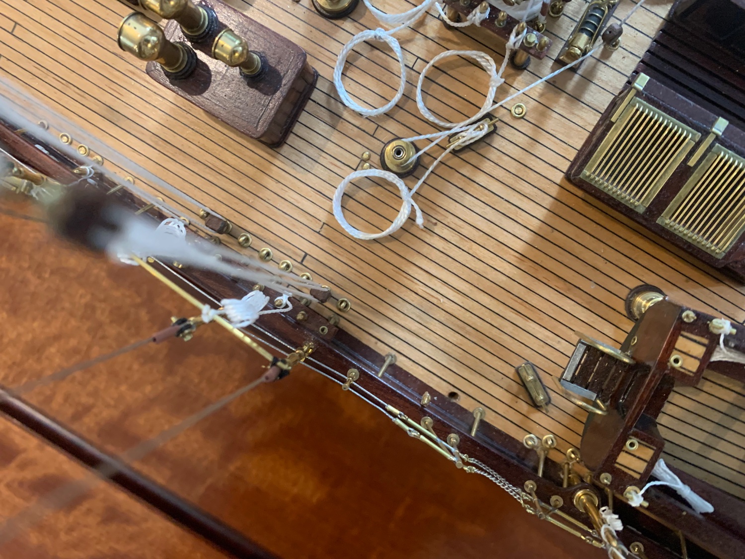
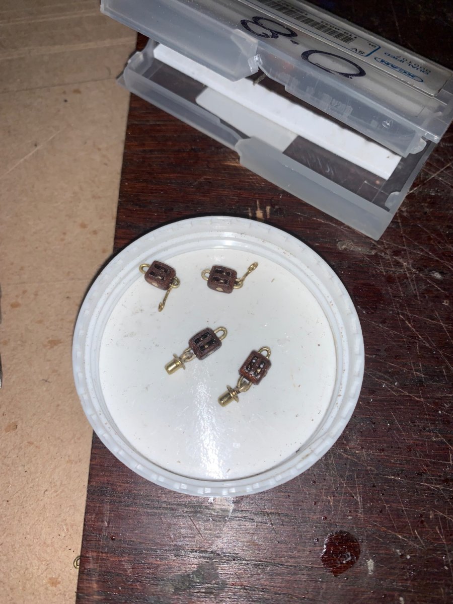
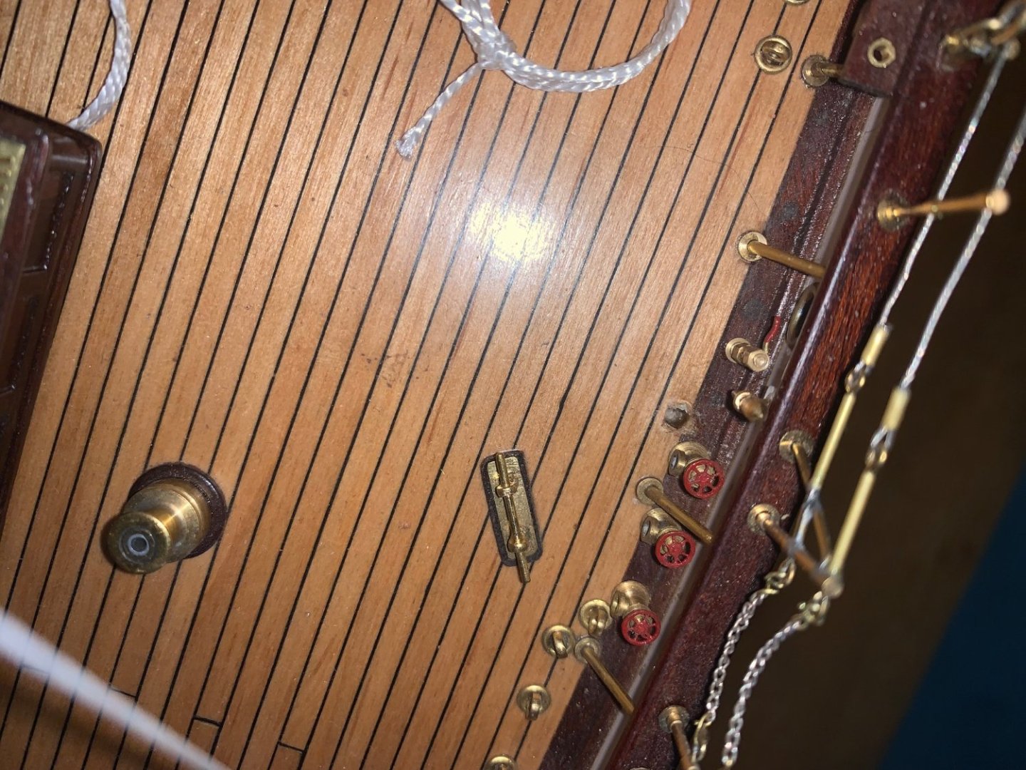
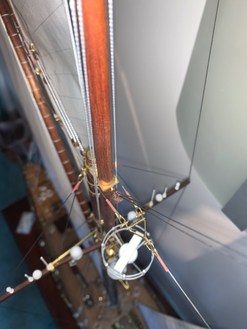
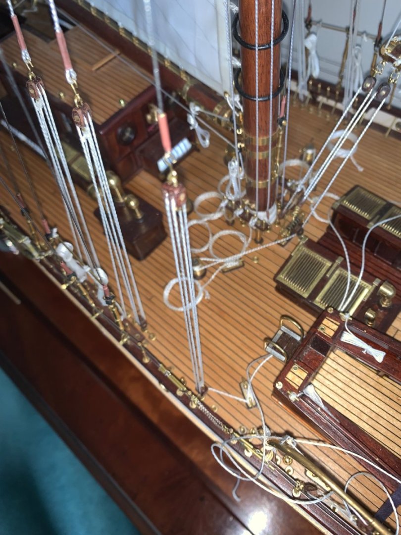
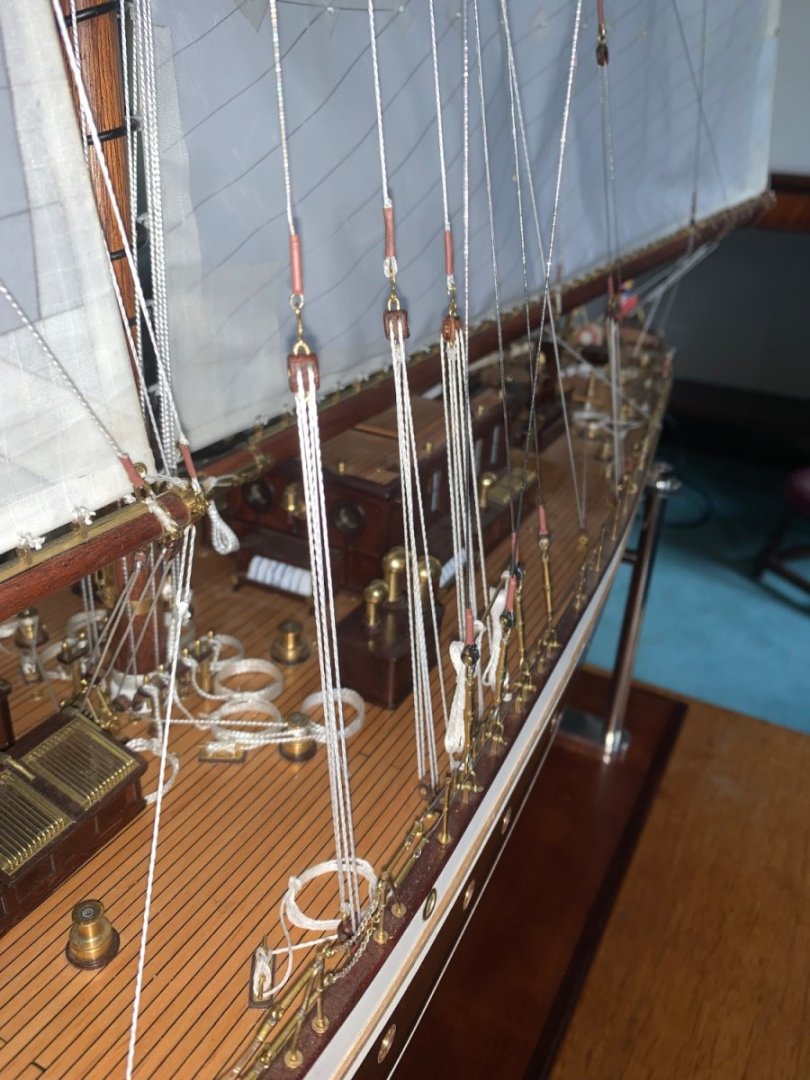
Im getting annoyed with myself that i am not finishing off this build, but thanks to everyone for sticking with me. I suppose that I was having and aversion to fixing mistakes but this weekend I managed to overcome my prevarication and fixed the problem. As I previously said the upper fore mast back stay had been rigged as a fixed stay. During a discussion on the complexity of tacking the fisherman it became obvious that I should have fitted a pair of running back stays with only the windward stay taking the load. Although I hadn't fitted a fisherman the change was made necessary by the nagging voice in my head. The change necessitated the production of 5 more twin blocks (one of which I managed to misplace). I found the 5th after a half hour hunt!!!!!!!!!! The fixed stay was removed and replaced by a pair of back stays wrapped around the upper fore mast, The pair were led to the twin block mounted high on the main mast. I had to remove a couple of deck hard points to mount the blocks - luckily they were glued in with CA and came free neatly with the application of a soldering iron. See hole next to the uppermost hand wheel. I managed to knock the hand wheel off (its smaller than it looks) and spent a good hour getting it back on - idiot!!! Rigging the blocks was the easy bit - but just twice ad difficult as it would have been had it got it right in the first place. It now feels fixed but most people won't notice. I also made some progress on the flags but dinner is ready so that will have to wait until next time.


-
Frightening. Maybe they need to consider fitting sails😀
-
Brain, looks interesting in a blunt sort of a way. I'm signing up .😀
-
Byrnes saw belt source in UK/EU?
KeithAug replied to bruce d's topic in Modeling tools and Workshop Equipment
Thanks Bruce. -
Good to see your sense of humour hasn't deserted you. The fact that they are contemplating letting you home tomorrow seems to be a good sign. Keep taking the morphine. Best wishes for a speedy recovery.
-
Yes Andy. The hull surface at the point of contact is curved in 2 axes and of course I also had to allow for the tolerance between the fore and aft vertical supports and the tolerance on the abeam width. The 4mm of adjustment that the eccentric rings gave me was very necessary.
-
i assume she doesn't follow your log. She may however start in the future!😀
-
Hakan - Belated best wishes re the surgery. It's now Tuesday evening and hopefully it will all be over and you will be on the mend. I hope the nurses are pretty and that you are chasing them round the ward by midday tomorrow.
-
Ras - I quite often use a mixture of solder and CA on components. I start with soldering but when I think structures are too complicated or small to protect from the heat of further soldering I revert to CA. Take care not to heat up brass which has been joined using CA. The heating will break the bond. Great job on the gun.
-
Eberhard - yes you are right - but the option of lowering the table might have ended in divorce and that is very expensive option at my time of life. Druxey - it doesn't look that bad in the flesh, I was clearly focusing on it in the photos which I think emphasised it. Brian - I'm not sure. I tried looking up compatibility but couldn't find rubber against poly. Fingers crossed. Eberhard, Druey, Rick, Keith, Tom, Steve, Brian, Mark - thank you all for your comments.
-
Mark - Thank you for you kind comments. A pig stick (occasionally pigstick[1] or pig-stick[2]) is a staff that carries a flag or pennant, usually the burgee of the boat owner's yacht club or private signal, above a mast of a sailboat.[3] The pig stick is connected to a halyard so that when raised to the top of the mast, it extends above the mast, allowing the flag to be seen flying above the boat's sails.
-
Byrnes saw belt source in UK/EU?
KeithAug replied to bruce d's topic in Modeling tools and Workshop Equipment
Thank you Bruce.