KeithAug
-
Posts
3,980 -
Joined
-
Last visited
Content Type
Profiles
Forums
Gallery
Events
Everything posted by KeithAug
-
 very nicely done
 -
Nice work Roger. How fine a blade do you have. My finest blade is a 108 tooth x 80mm x O.6mm kerf but even this is a bit “choppy” on thin brass. I frequently revert to gluing brass sheet to 1/8” ply and filling circular and square sections will wood to get smooth cuts. It would be good to hear how you do it?
-
Tom. Brass cylinders .075” diameter by .080” long. thank you for your comments Gary and Brian.
-
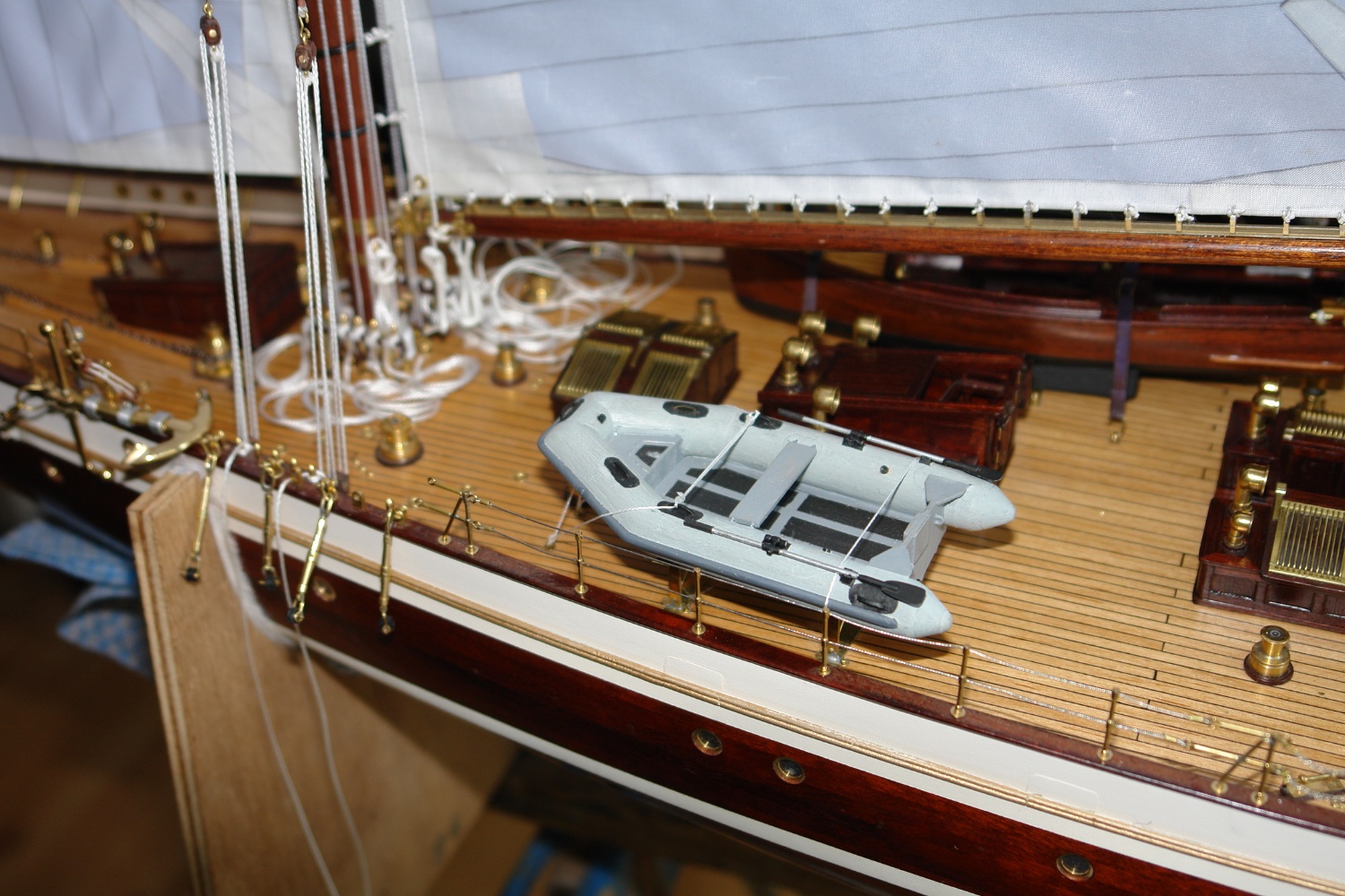
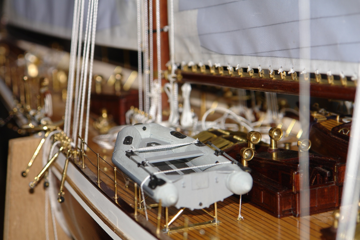
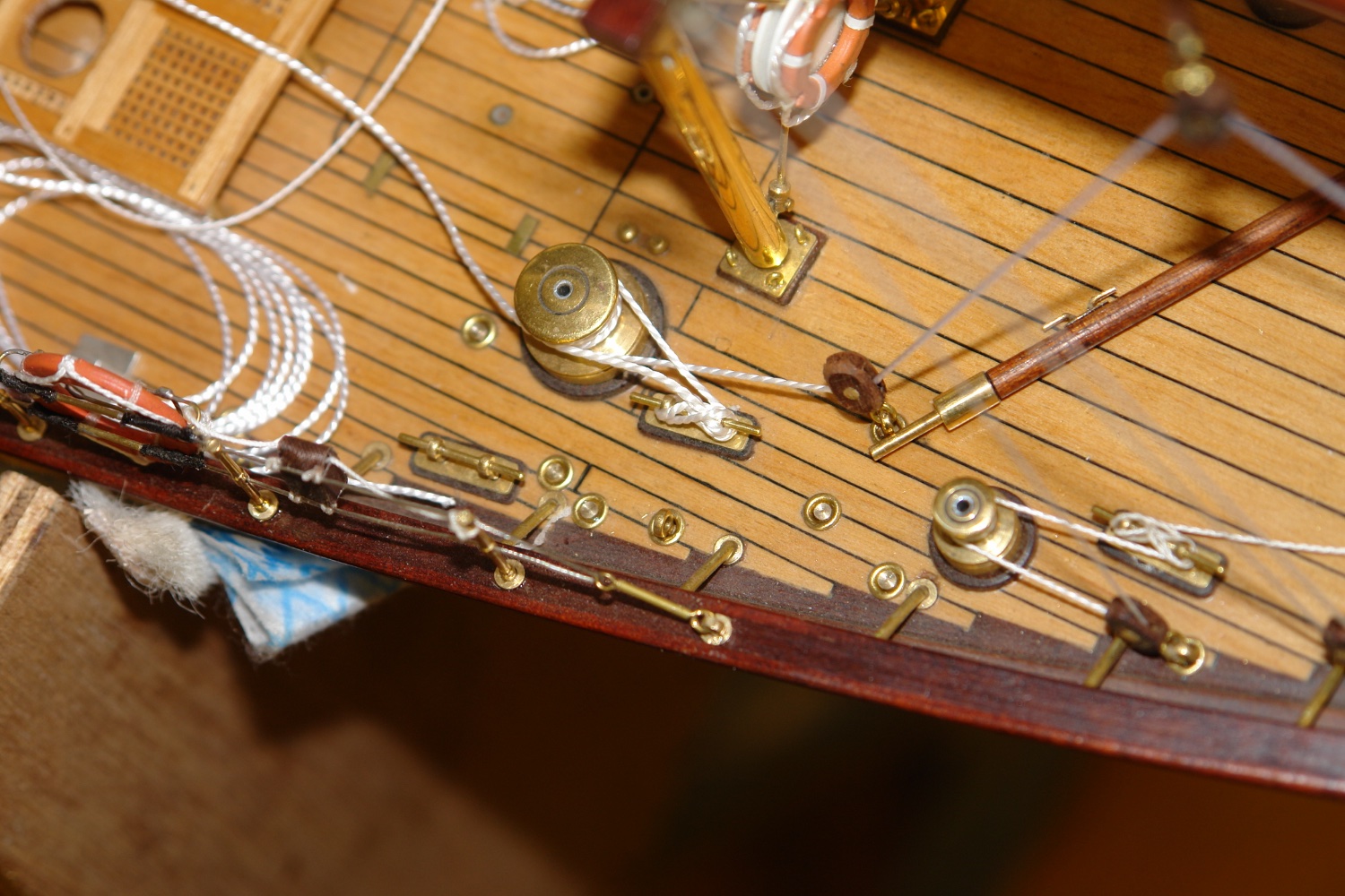
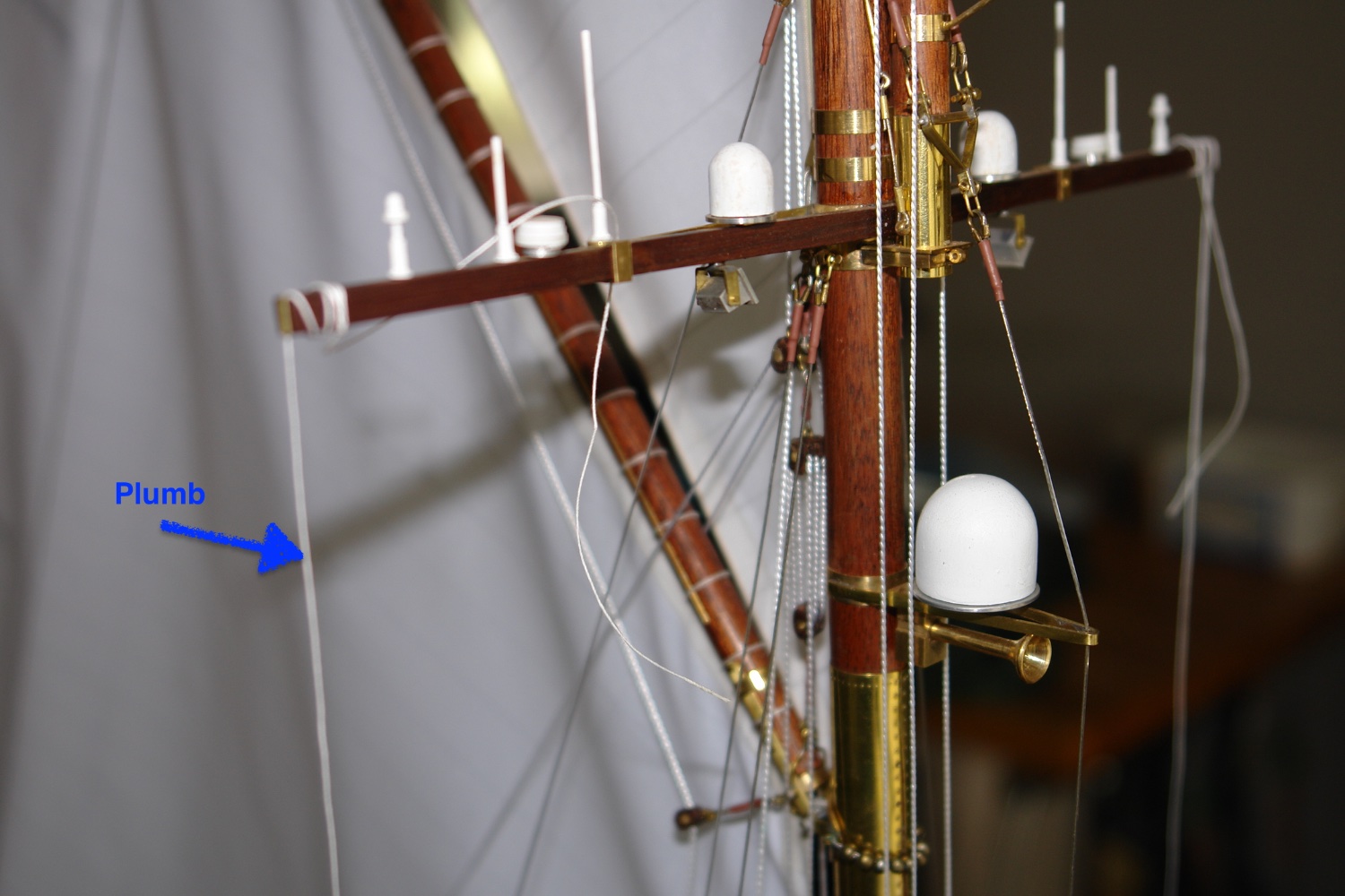
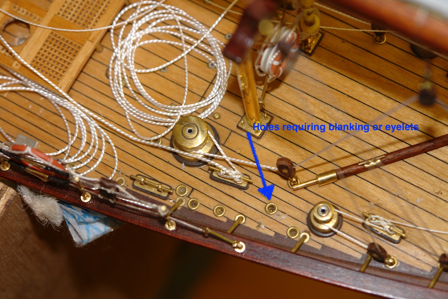
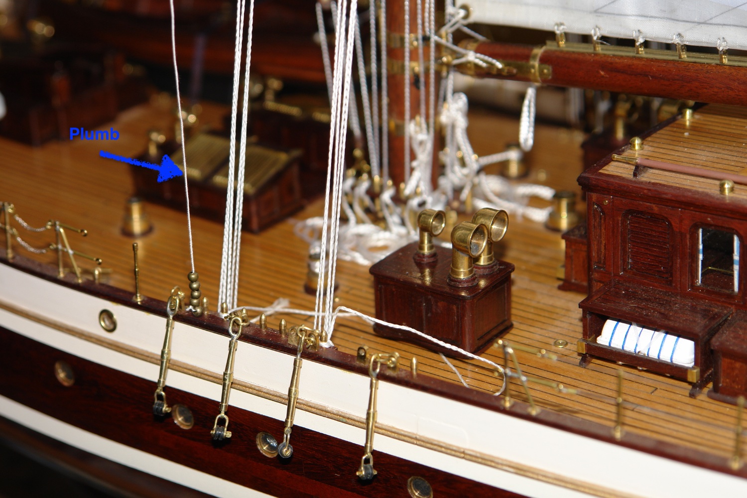
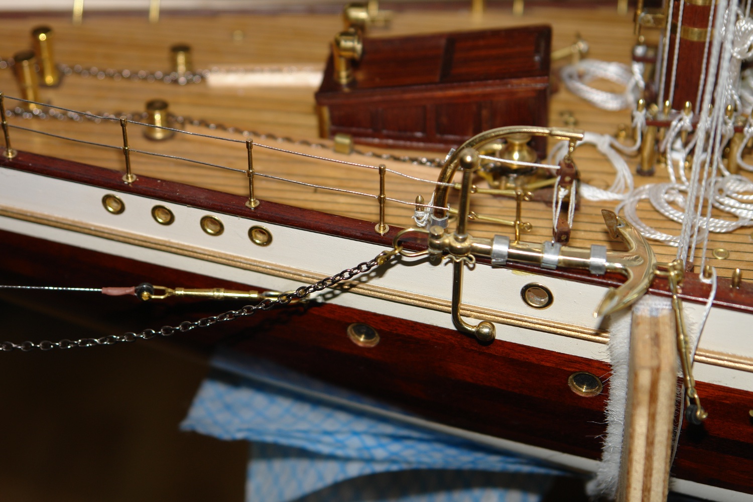
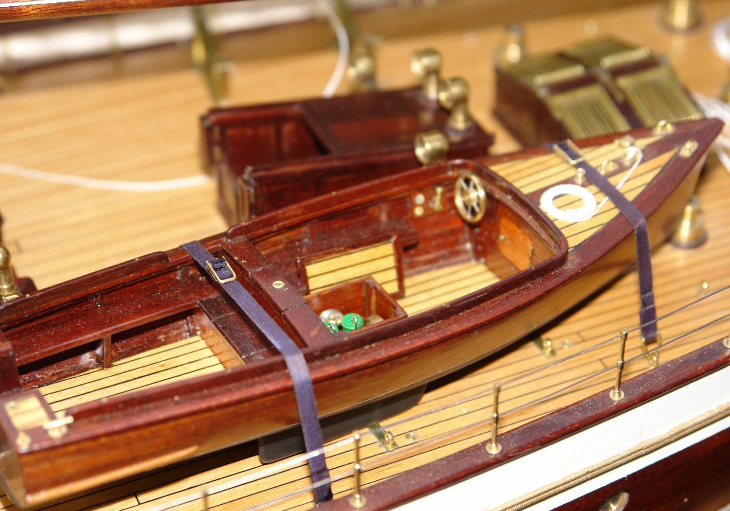
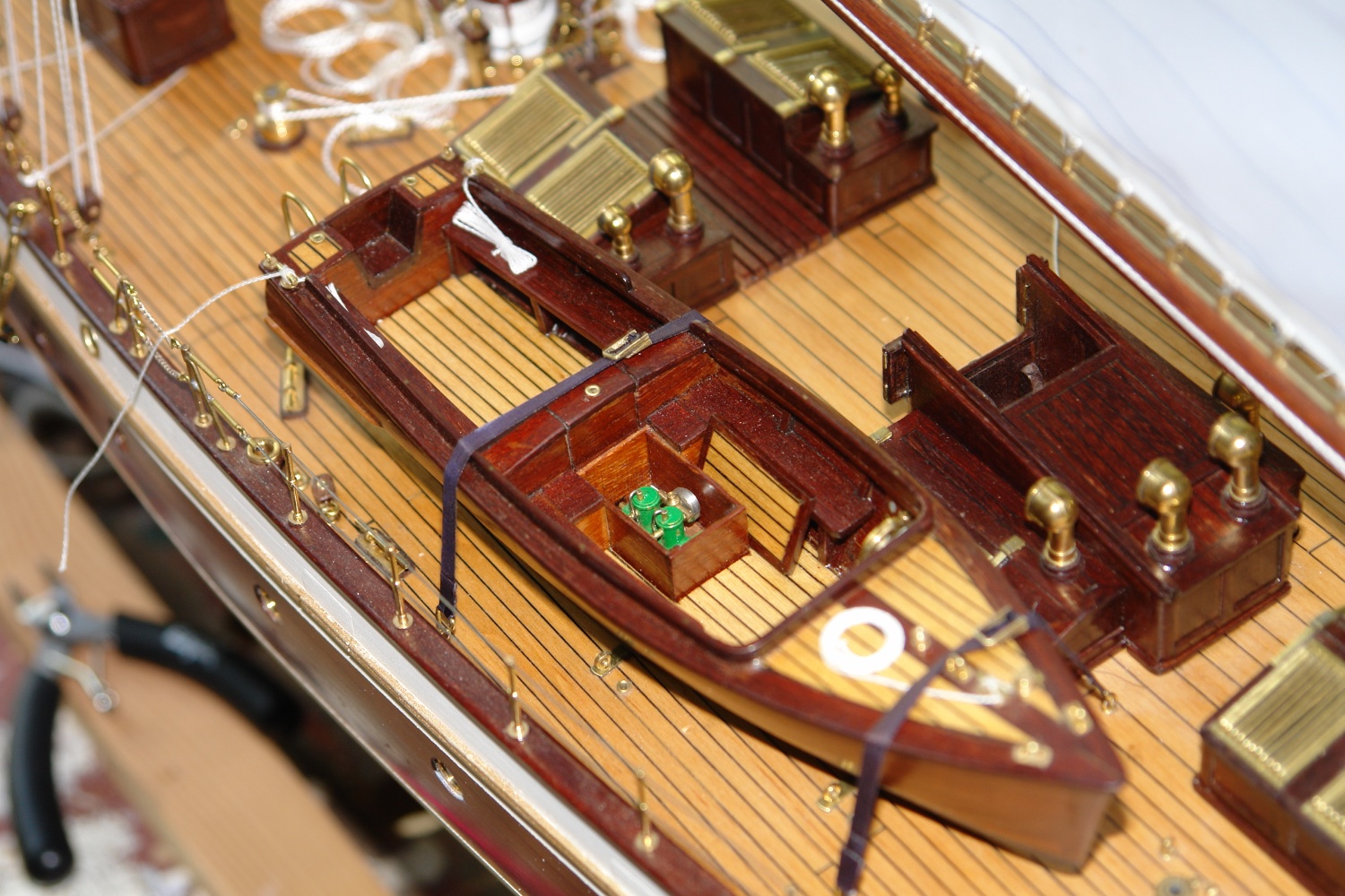
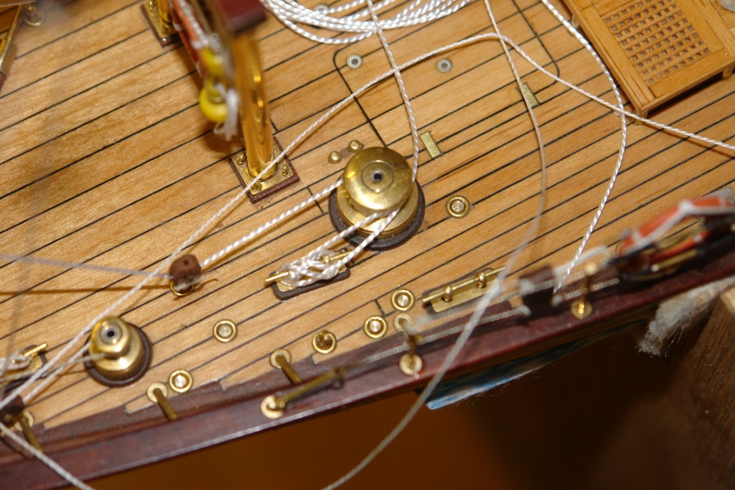
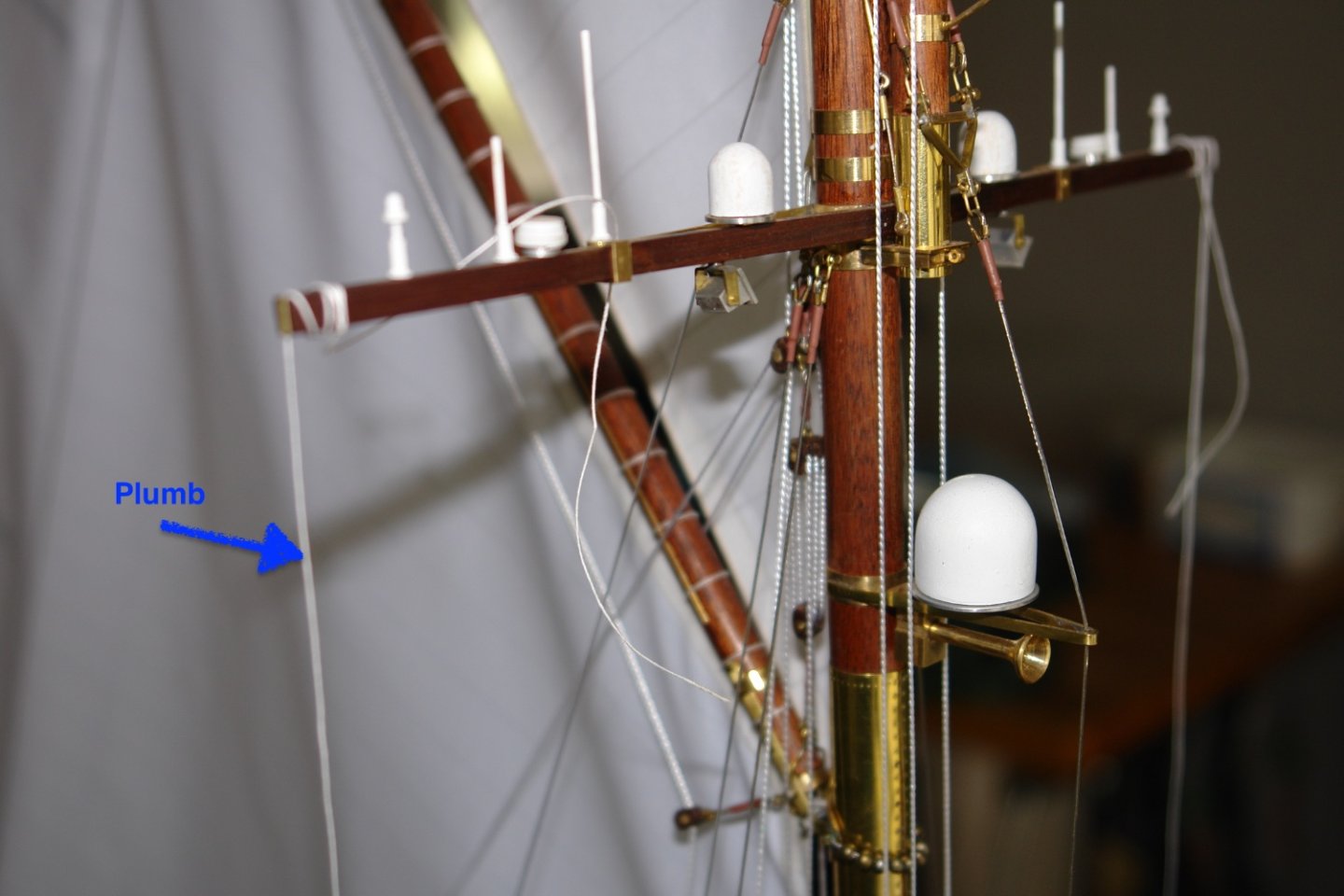
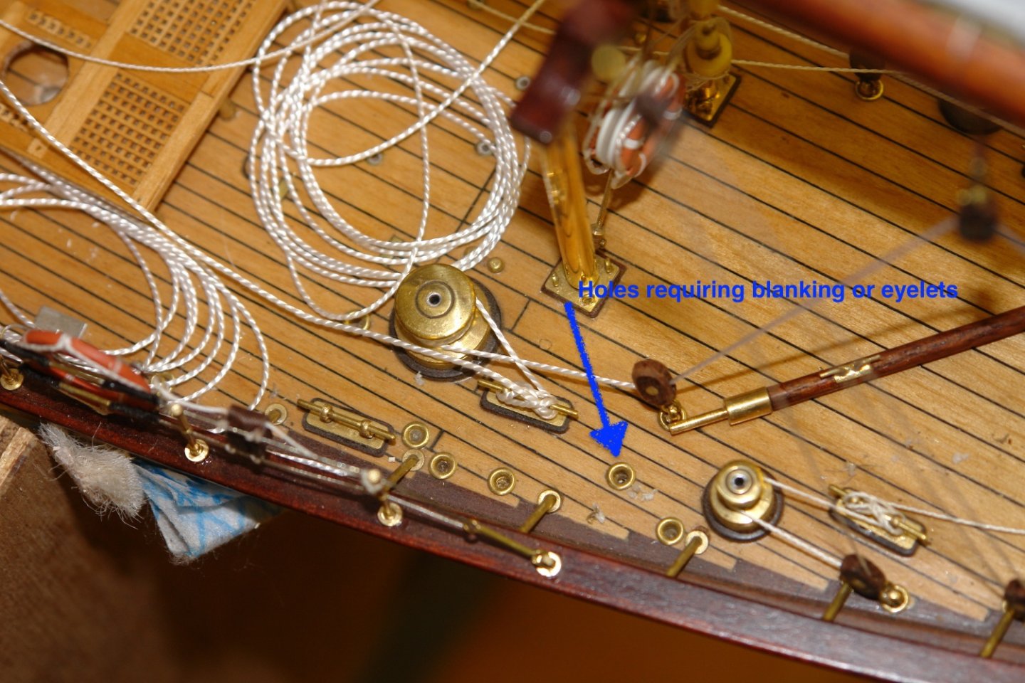
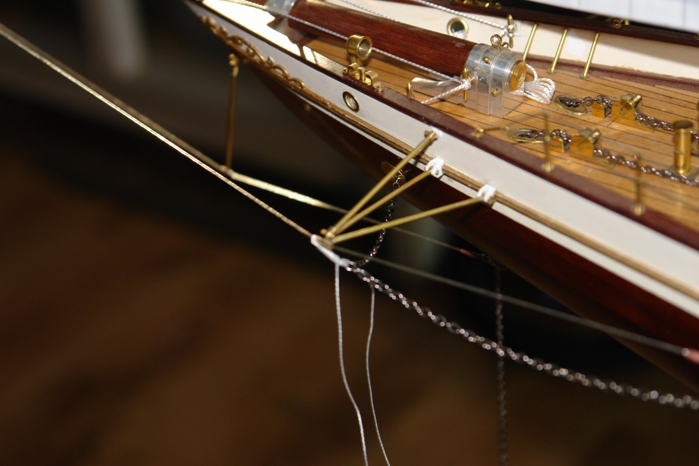
Pat, Brian, Todd, Eberhard, Tom, Mark, Druxey, CPDDET - trank you all for commenting. Not a lot done in the last couple of days - so small update. I lashed the dinghy in place, I don't know why but it seemed more appropriate to fasten it down with line (probably because almost every yacht i have been on takes this approach). All the deck eyes had been installed some time ago so it was just a case of deciding on how the lines would run. The chosen arrangement seemed particularly secure. The masts at this stage weren't actually glued in place and I wanted to get the alignment of the cross trees spot on so I used a pair of improvised plumb lines. These were dropped from the ends of the cross trees and aligned against the turnbuckle attachment points on the rail. A spot of glue was then applied to the base of the fore and main masts to lock them in place. Then came quite a laborious task of installing the remaining eyes and blanking plugs in the deck rigging attachment points. There were about 50 such holes left to fill. As I said - somewhat of a low productivity weekend.


-
Time to crank up the shed heater.
-
Hakan, yes I get those days. I find the trick is to recognise them early and go off and do something else. I sometimes get the balance right but more frequently kick myself for not quitting sooner.
-
Yes - very neatly done.
-
Brian - alignment Print the flag on a piece of paper. Tape the "tissue" paper over the printed flag and reprint the flag on to the tissue. Remove the tissue and flip it over and carefully align the printed tissue paper image with the image on the paper. Tape it in position. Re print the image on the reverse side of the tissue paper. Hopefully the images on the two sides match. Having said that your chosen flag looks great.
-
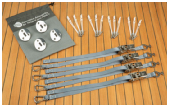
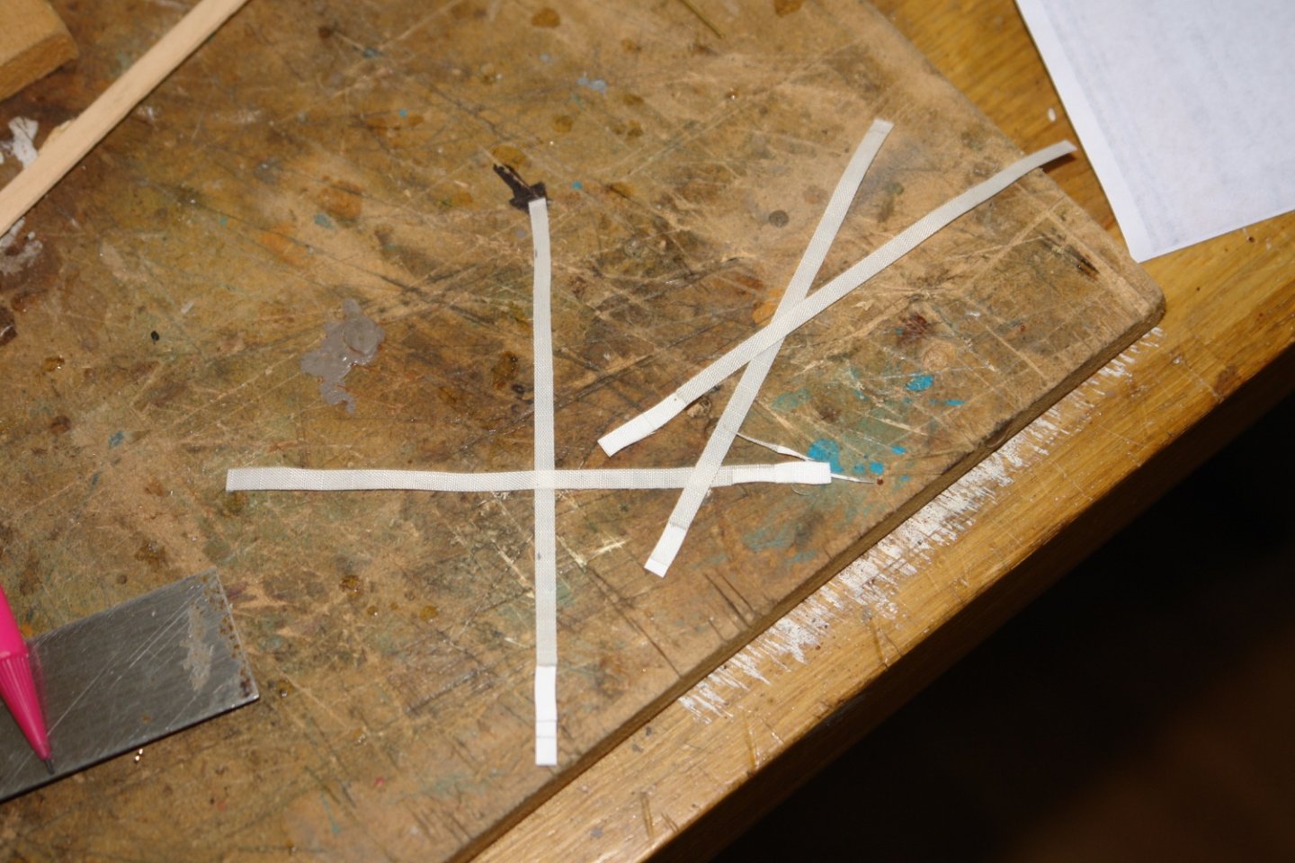
Eberhard, I didn't have a lot to go on so I looked up retains straps for boat tenders and this is what I found:-
-
Brian - yep that looks pretty good, have you considered trying the same process but with a single layer of paper printed on both sides?
-
Brian I'm looking forward to seeing and learning from your flag experiments. I think it is time you stopped pretending this is your first scratch model, you are fooling no one😁.
-
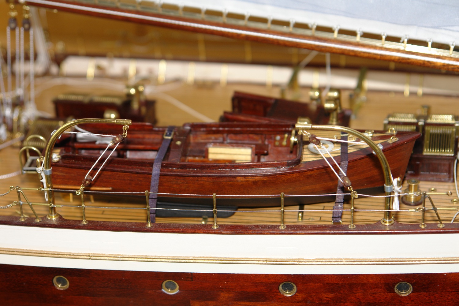
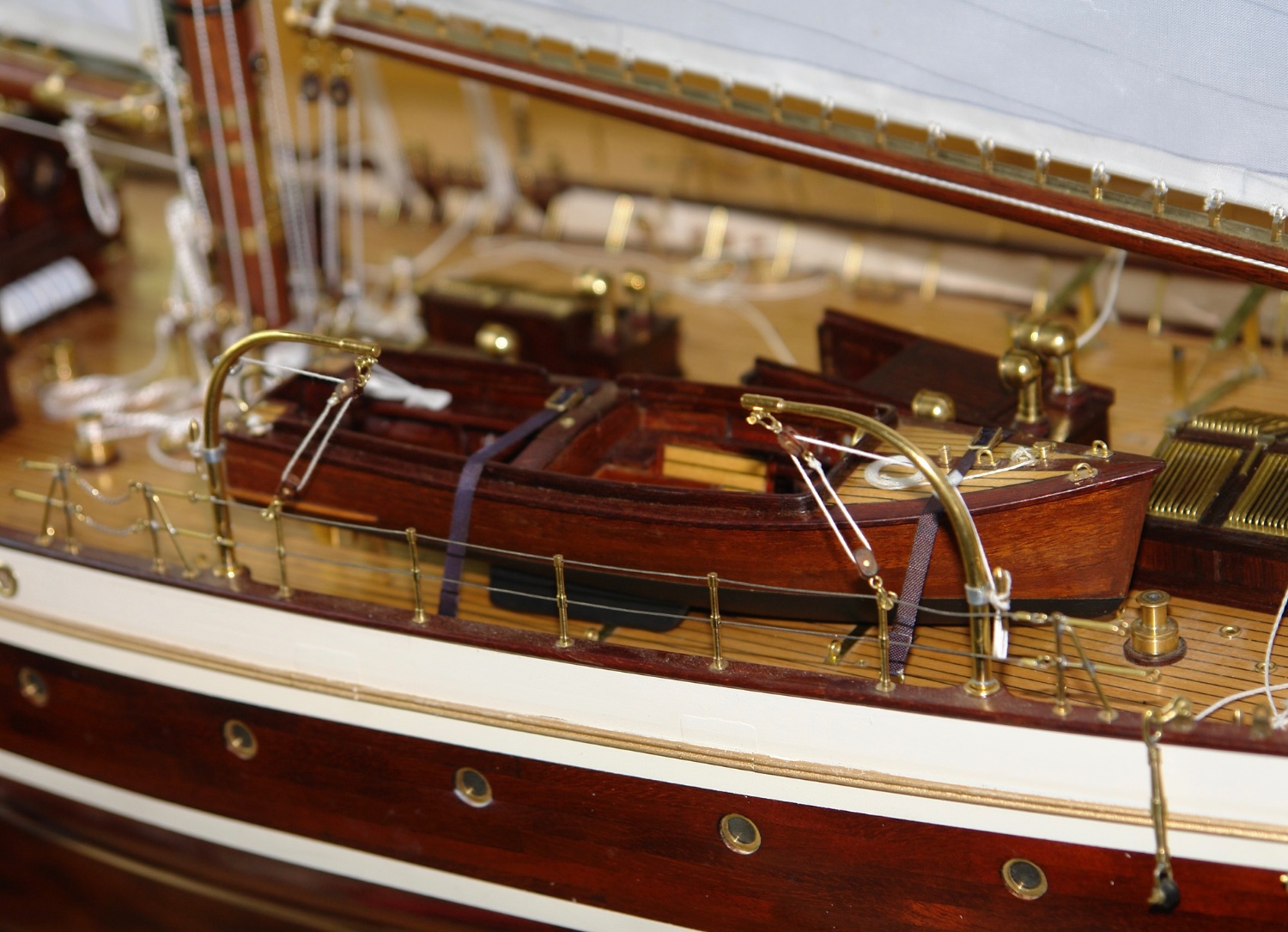
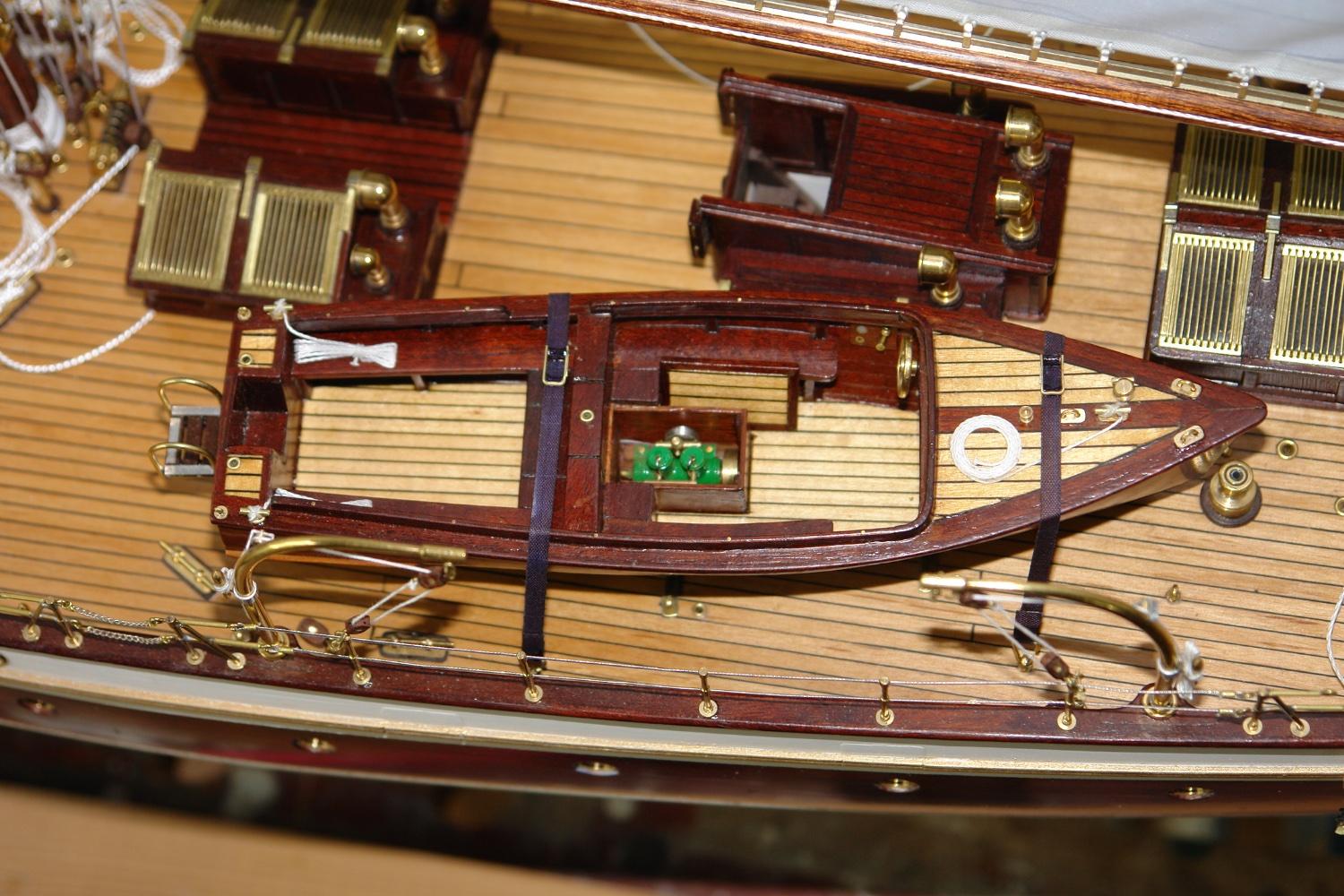
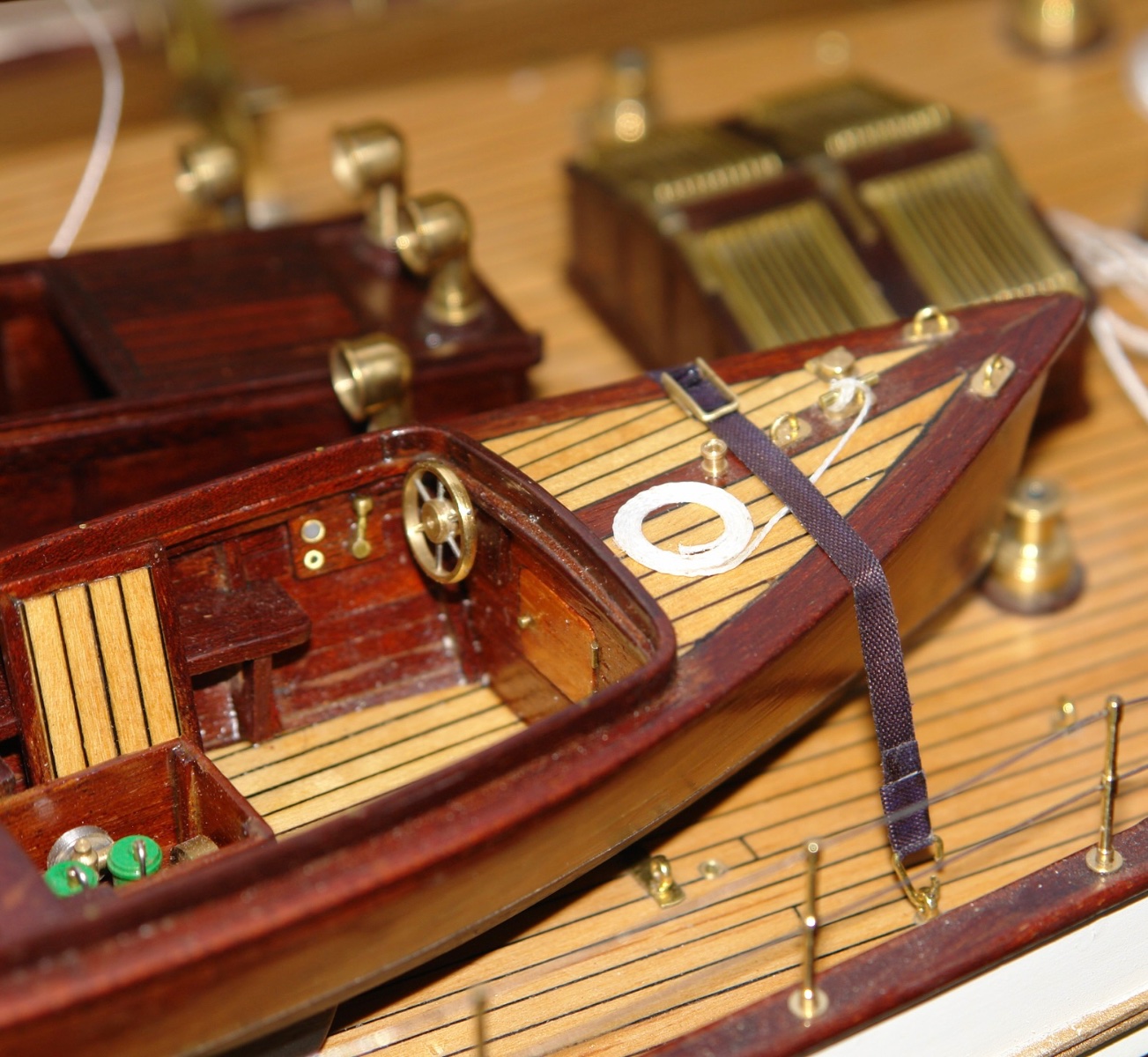
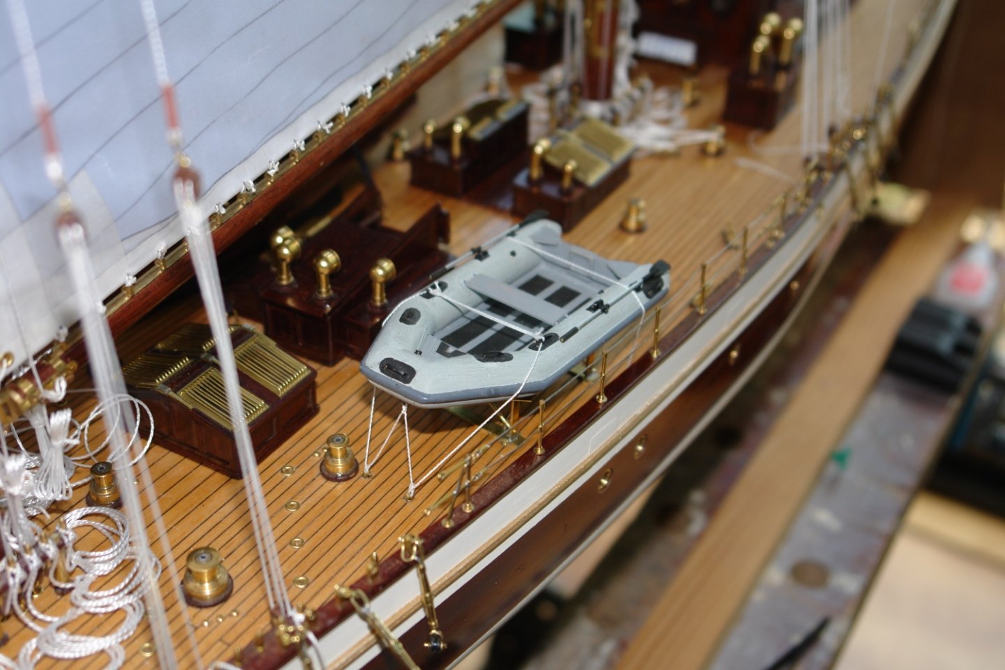
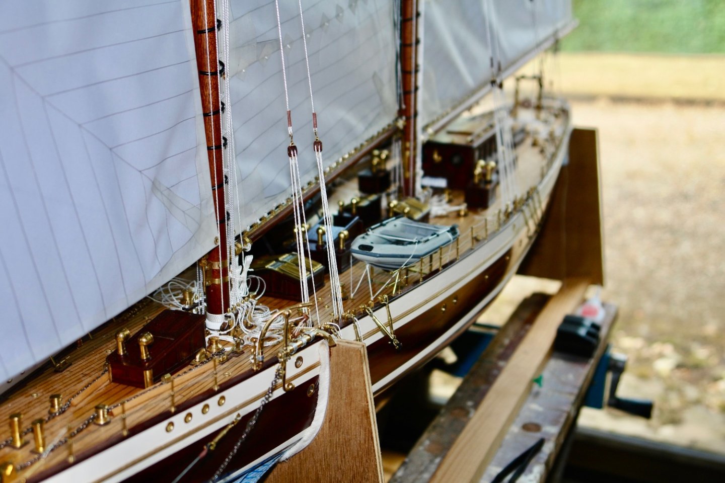
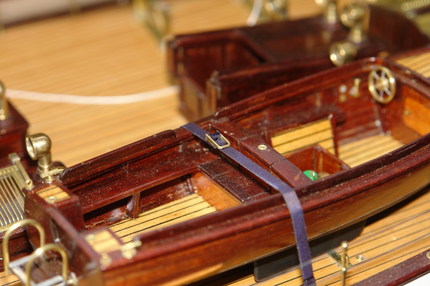
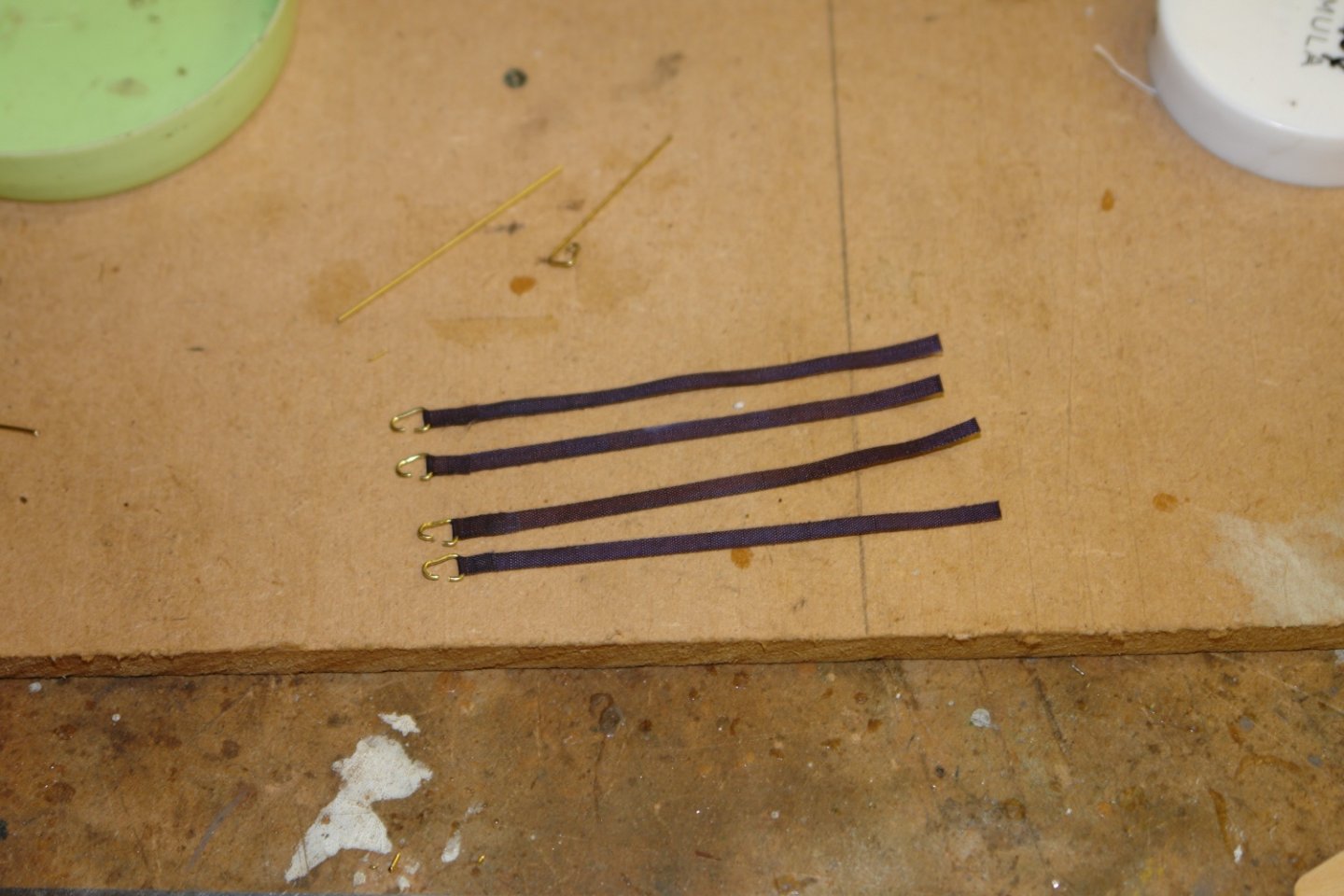
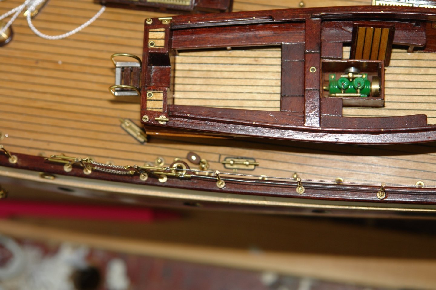
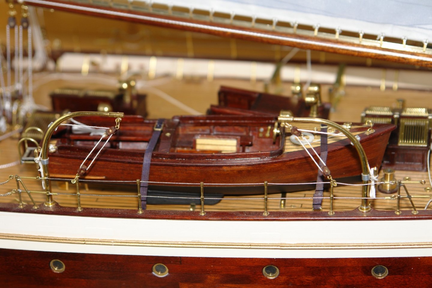
This week I continued working on the deck mounted items. I had mounted the anchors but not attached the chains so this was the next job. The chains were attached to the anchors with a shackle and then they were lashed to the tripod frames bracing the jib martingales. Next it was time to mount the tender on the deck. I needed webbing straps to hold the tender to the deck and these were made from ripstop tape. Simple attachment brackets were made and these were attached to the straps. The webbing straps were stained black with a permanent marker. I then needed to simulate tightening ratchets. The straps / brackets had to be assembled once the tender was in place. I added the (cotton) painter to the tender before attaching the strap. The close up photos remind me that a good dusting is required. A second strap holds down the stern of the tender. Stern mooring lines were required. Finally the boat davits were completed and mounted.


-
A pretty little thing, well done.
-
HMCSS Victoria 1855 by BANYAN - 1:72
KeithAug replied to BANYAN's topic in - Build logs for subjects built 1851 - 1900
What are they made from Pat? I cant work out whether they are wooden or printed.- 1,013 replies
-
- 2
-

-
- gun dispatch vessel
- victoria
- (and 2 more)
-
Cort - I did wonder if you planned to live in it. Are you going to paint a wrap around mural for viewing through the windows? I am not sure about the lap top. I don't remember seeing one in the film
-
Fascinating. What are your plans for the completed reproduction once finished?
-
Amazing, and fabulous attention to detail. A great resource for future “miniature modellers but I can hear the groans of those who have completed models and are now reevaluating their models.
-
Thank you Roger. I have copies of the 2006 and 2008 papers but not the third paper you mention. I am aware from photographs that the original riveted hull was replaced with a welded hull so like you I assume the lines drawings exist I just haven’t found a reference to them. My best bet will be to try an email to the restorer. Thank you for the tip Dan, I wasn’t aware of this but will follow it up. Thanks to everyone for the continued interest and likes.
-
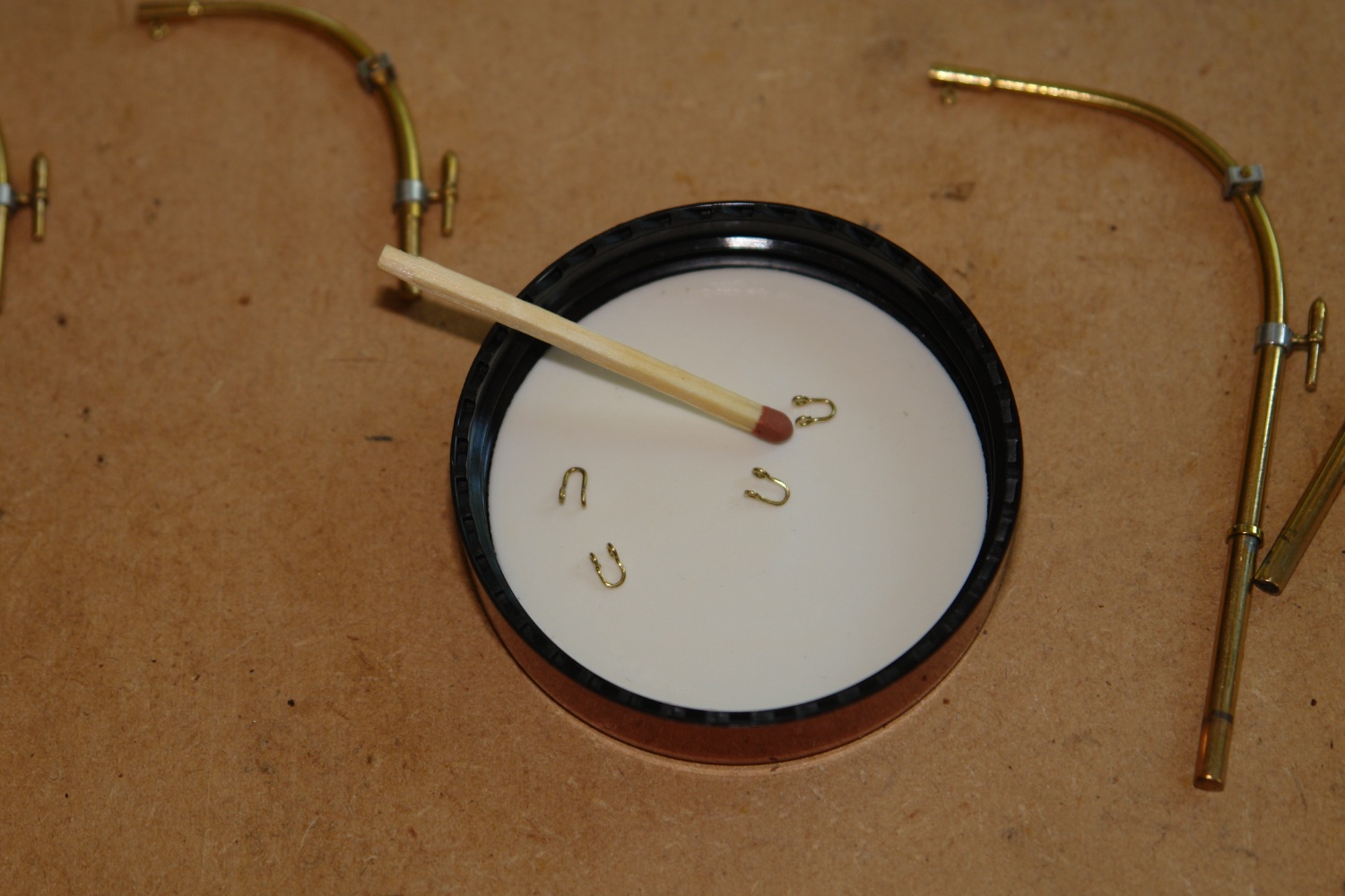
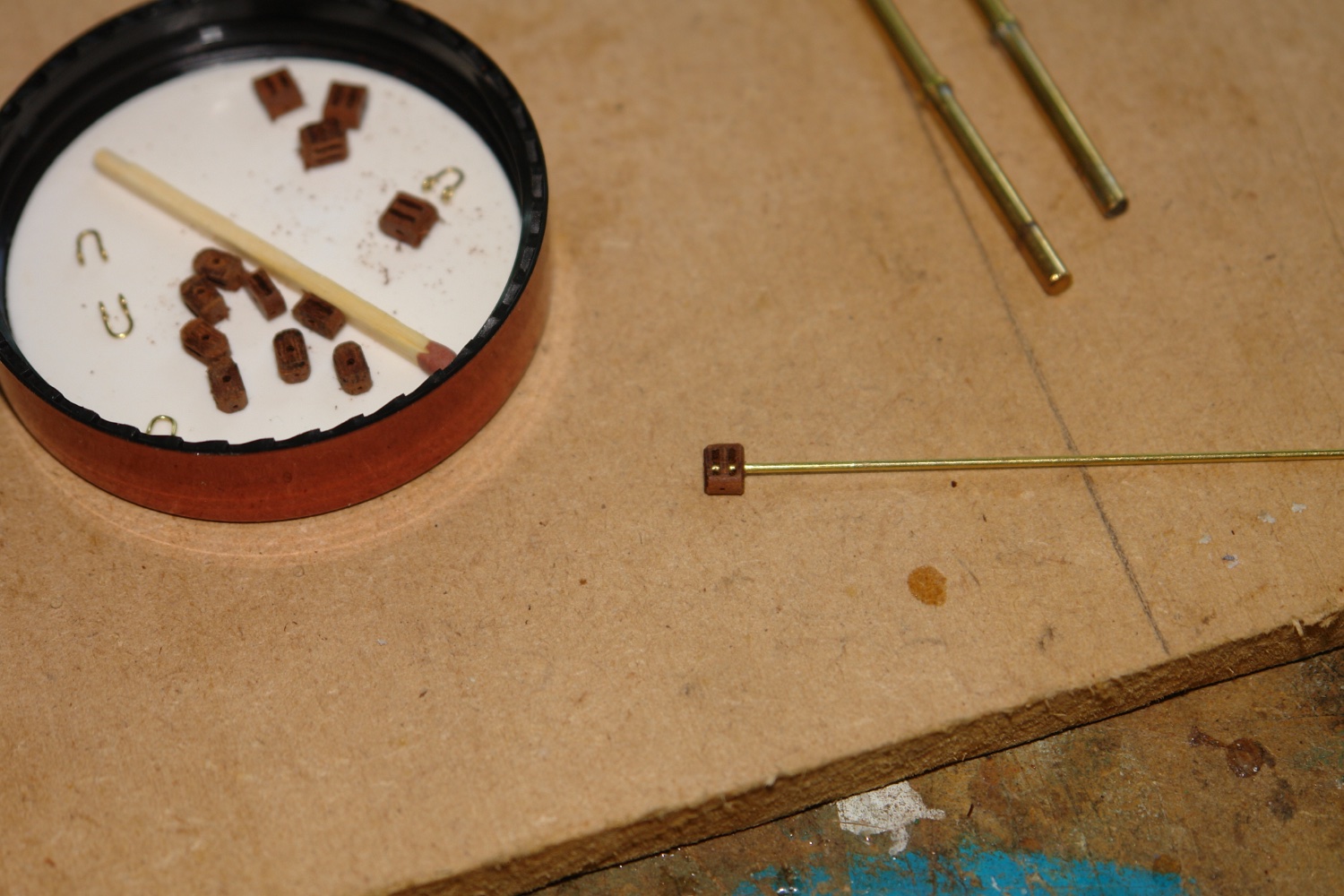
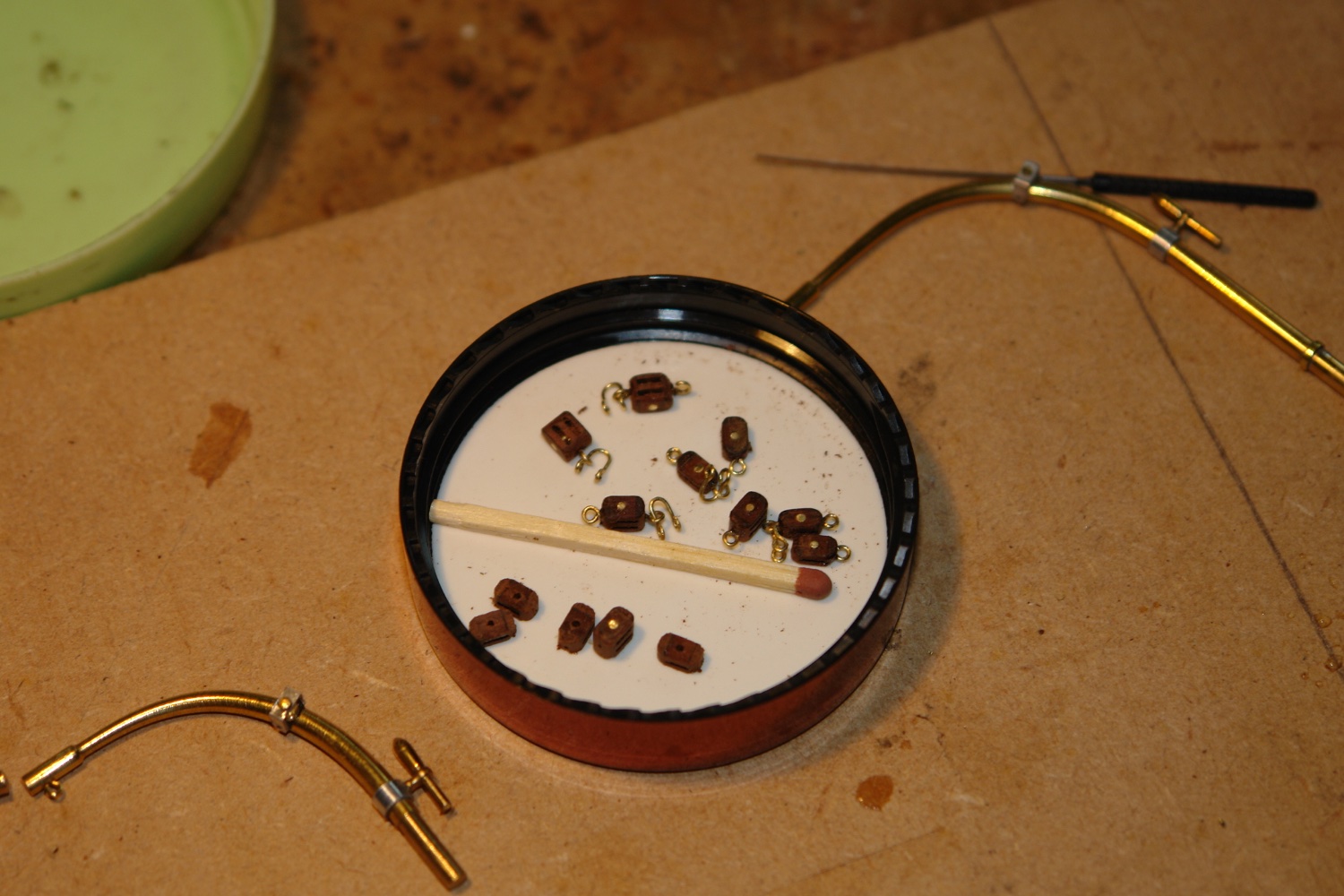
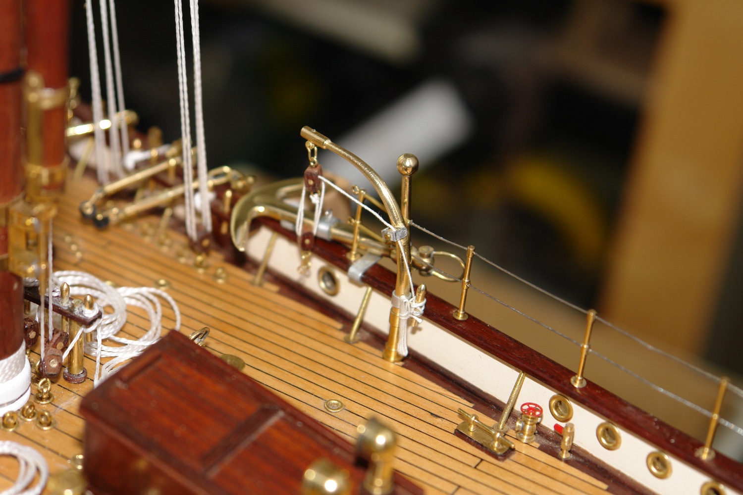
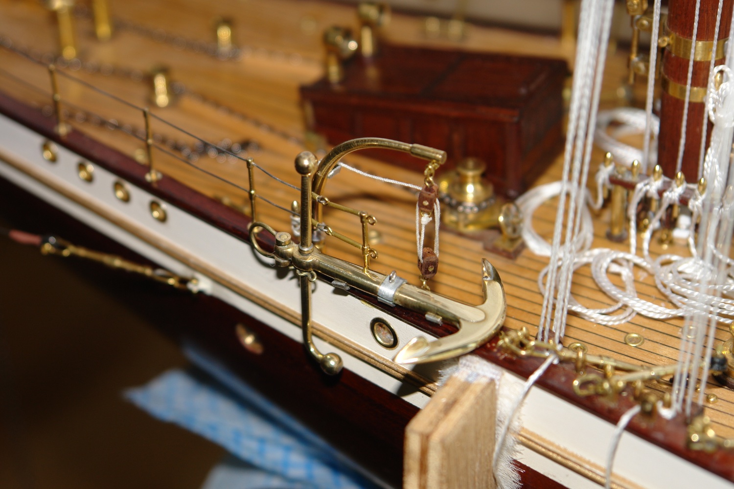
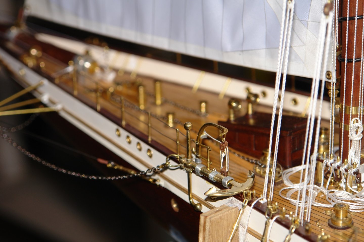
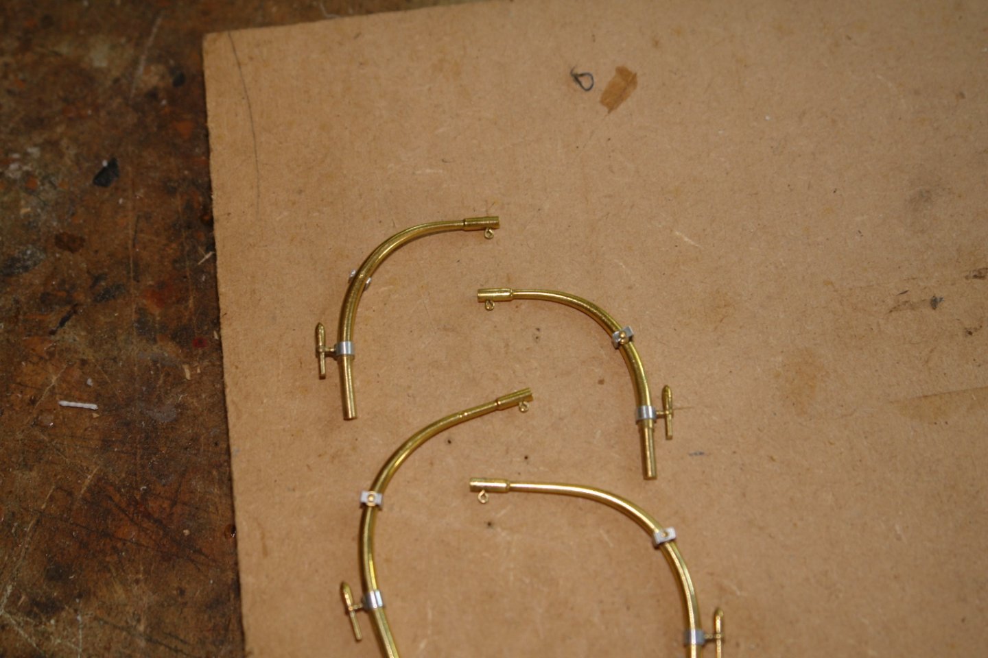
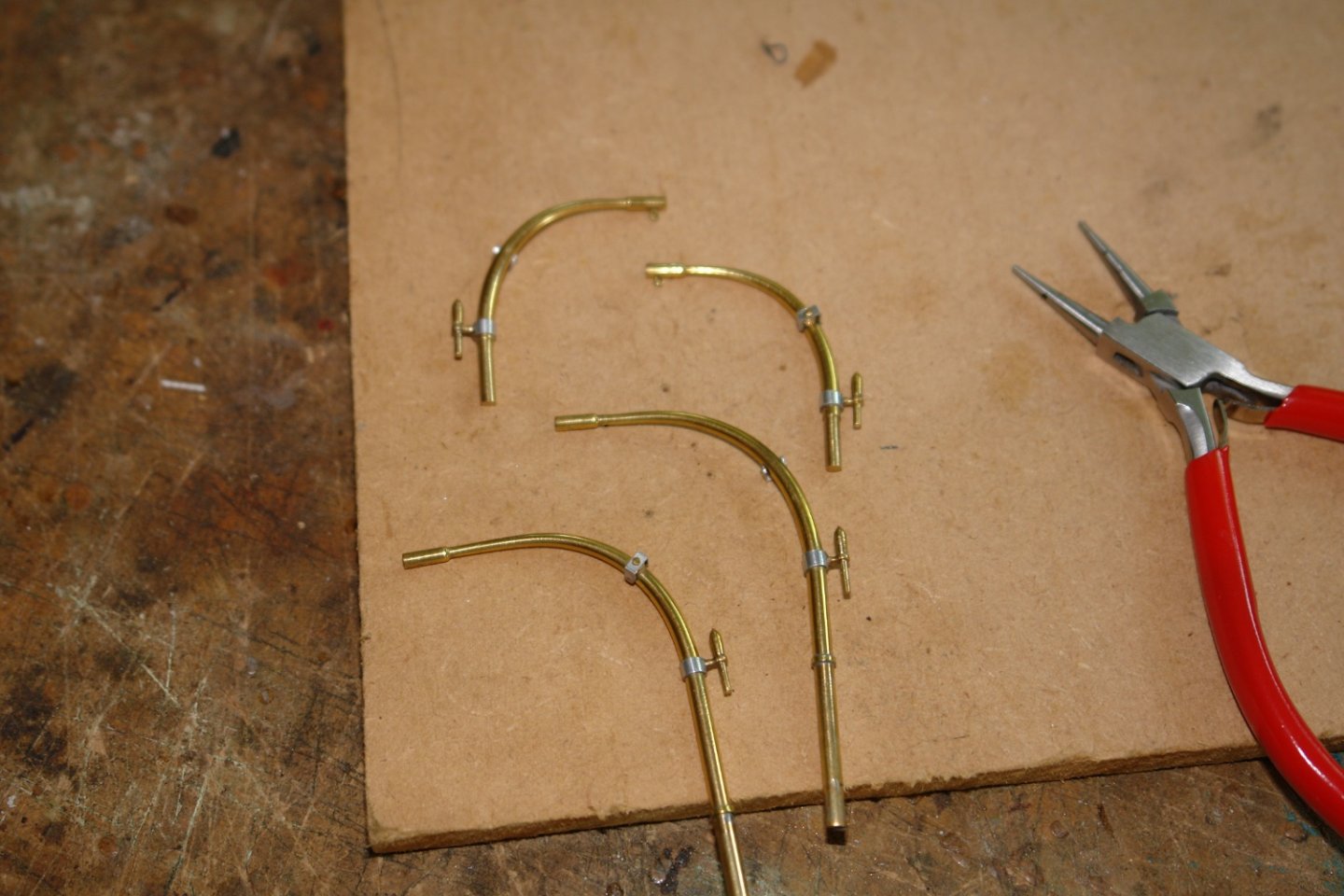
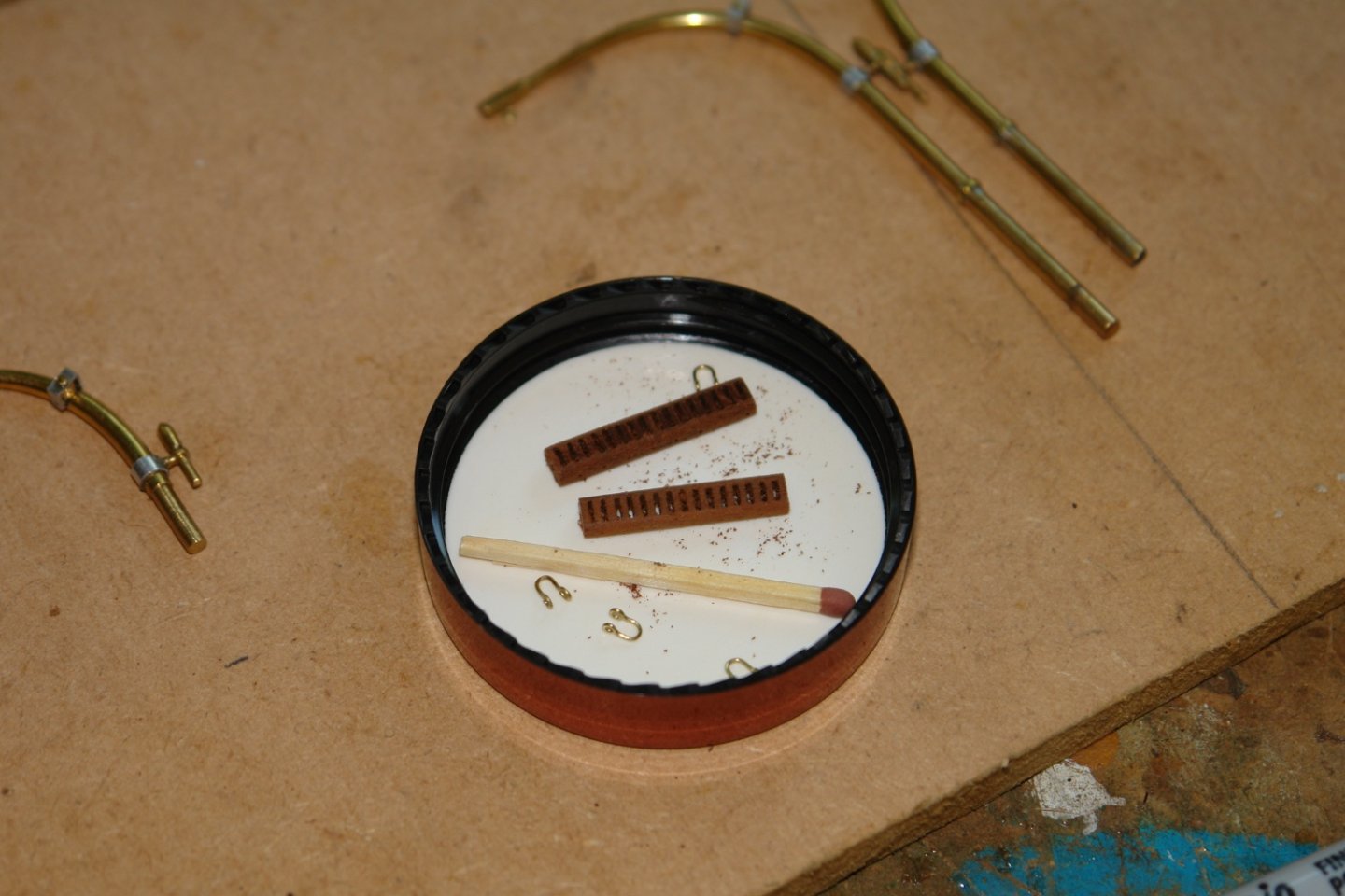
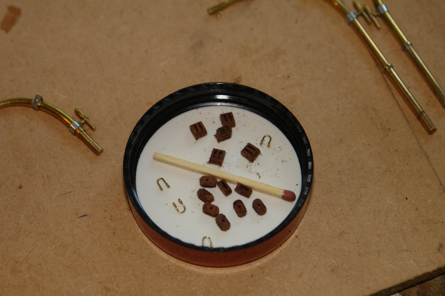
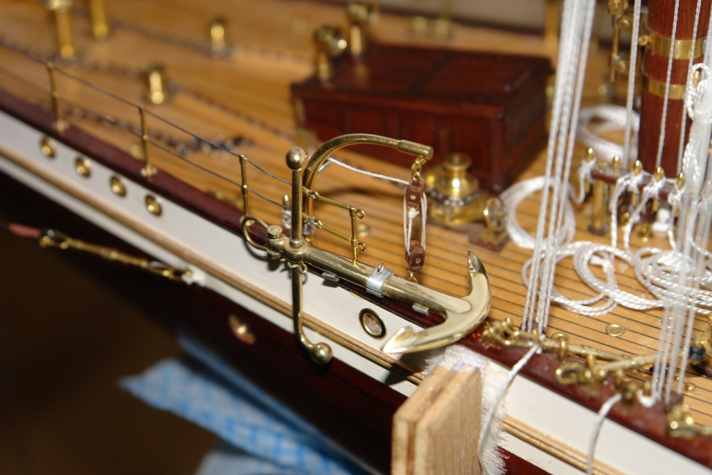
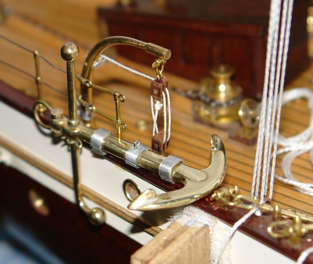
Phil - Thank you for your comments. I don't know Delphine but on your prompting will do a bit of investigating. Thank you. As I said last time I decided to have a bit of a rest from rigging. I think that completing as many of the deck fittings as possible before completing the shrouds is probably sensible. I thought I would finish off the davits. These were substantially completed some time ago. The small ones are for the anchor and the boat steps while the large ones are for the tender. I needed to make and attach the blocks so I started by attaching the block attachment eyes to the davits. I also entered another phase of shackle and block making. I had previously made the block "strips". I needed both double and single blocks so I parted off a number of each. And then installed the shaft before rounding off the edges with fine sandpaper. The block attachment features (eyes and shackles) were then attached. I then rigged the anchor davit using fine cotton. The anchor (again made some time ago) was glued on to the rail brackets. And finally the anchor retaining straps were added. I also started scratch building a small pond yacht for my granddaughter - hopefully Santa will deliver it.


-
Rick, thank you very much. Anything you can get would be useful. What I usually find is that internal and the main deck features are usually covered reasonably well on web photographs. What is generally more difficult to find is photos of the rigging and fittings above eye level. I would prefer to model Cangarda with her auxiliary sailing rig set but I haven't found any photographs of this. As I said any help would be most welcome. Best regards
-
Grinding your own lathe tools?
KeithAug replied to CPDDET's topic in Modeling tools and Workshop Equipment
If you want to mill the tool to shape i suggest the following:- Buy some silver steel. Mill the shape you want into it. Heat to cherry red and then quench in cold water. (this hardens the tool so that it retains an edge) Touch up the edges with a diamond file if necessary. Silver steel in its unhardened form can be cut quite easily with HSS tools. I often use this technique for making tools for cutting brass so it will be fine for cutting wood. -
Fabulous Brian. I love the set of the windows on the side of the paddle wheel housing. It looks a bit like a building from Lord of the Rings. You made a particularly good job of modelling the ships dog, it is incredibly realistic.
-
Yes I agree with everyone. i don't know where you get all the time from. it must take an age to make each one.